
Federal Ministry for the Environment, Nature Conservation ... Technical Rules on Installation Safety...
41
translation for informational purposes - Original in German I The official version of this TRAS 320 “Vorkehrungen und Maßnahmen wegen der Gefahren- quellen Wind sowie Schnee- und Eislasten“ was published in the Bundesanzeiger of 16.07.2015. Federal Ministry for the Environment, Nature Conservation, Building and Nuclear Safety Publication of a Technical Rule of the Commission on Process Safety (TRAS 320 – ‘Precautions and Measures against the Hazard Sources Wind, Snow Loads and Ice Loads’) Of 15 June 2015 A technical rule elaborated by the Commission on Process Saf ety, ‘Precautions and Measures against the Hazard Sources Wind, Snow Loads and Ice Loads’ (TRAS 320), is published hereinafter. The text of the Technical Rule may also be downloaded via the Internet from the following address: www.kas-bmu.de/publikationen/tras/TRAS_320end.pdf. Bonn, 15 June 2015 Federal Ministry for the Environment, Nature Conservation, Building and Nuclear Safety For the Ministry
Transcript of Federal Ministry for the Environment, Nature Conservation ... Technical Rules on Installation Safety...

translation for informational purposes - Original in German
I
The official version of this TRAS 320 “Vorkehrungen und Maßnahmen wegen der Gefahren-
quellen Wind sowie Schnee- und Eislasten“ was published in the Bundesanzeiger of
16.07.2015.
Federal Ministry for the Environment, Nature Conservation, Building and Nuclear Safety
Publication of a Technical Rule of the Commission
on Process Safety (TRAS 320 – ‘Precautions and Measures
against the Hazard Sources Wind, Snow Loads and Ice Loads’)
Of 15 June 2015 A technical rule elaborated by the Commission on Process Safety, ‘Precautions and Measures against the Hazard Sources Wind, Snow Loads and Ice Loads’ (TRAS 320), is published hereinafter. The text of the Technical Rule may also be downloaded via the Internet from the following address: www.kas-bmu.de/publikationen/tras/TRAS_320end.pdf.
Bonn, 15 June 2015
Federal Ministry for the Environment,
Nature Conservation, Building and Nuclear Safety
For the Ministry

translation for informational purposes - Original in German
II
Technical Rule on Installation Safety:
Precautions and Measures against the
Hazard Sources Wind, Snow Loads and
Ice Loads
TRAS 320

translation for informational purposes - Original in German
III
Contents
Preamble .............................................................................................................................. 1
1 Foundations – Requirements laid down in the Major Accidents Ordinance
(StörfallV) ...................................................................................................................... 1
2 Scope ............................................................................................................................. 4
3 Definitions ...................................................................................................................... 5
3.1 Hazard source ....................................................................................................... 5
3.2 Environmental hazard sources ............................................................................... 5
3.3 Hazard source analysis .......................................................................................... 5
3.4 Analysis of hazards and threats ............................................................................. 6
3.5 Wind ...................................................................................................................... 6
3.5.1 Extreme wind ..............................................................................................7
3.5.2 Wind velocity ...............................................................................................7
3.5.3 Gust ............................................................................................................7
3.5.4 Peak wind ...................................................................................................7
3.5.5 Tornado ......................................................................................................7
3.6 Snow load .............................................................................................................. 9
3.6.1 Exceptional snow load ................................................................................9
3.6.2 Extreme snow load......................................................................................9
3.7 Ice load .................................................................................................................. 9
3.8 Wind-induced projectile .......................................................................................... 9
3.9 Disruption to normal operation caused by wind, snow loads and ice loads ..............10
3.10 Protection concept ................................................................................................10
3.11 Installation-specific protection aims .......................................................................10
3.12 Precondition for the occurrence of a major accident ..............................................11
4 Systematic approach and structure of the present Technical Rule on
Installation Safety ........................................................................................................11
5 Description of hazard sources ....................................................................................14
5.1 Hazard sources caused by static and dynamic loads ............................................14
5.1.1 Hazard sources caused by wind loads ...................................................... 14
5.1.2 Hazard sources caused by vibrations ........................................................ 15
5.1.3 Hazard sources caused by snow loads and ice loads ............................... 16
5.2 Hazard sources caused by wind-induced projectiles, air pressure changes
and pressure fluctuations ......................................................................................16
5.2.1 Hazard sources caused by wind-induced projectiles ................................. 16
5.2.2 Hazard sources caused by air pressure changes and pressure
variations .................................................................................................. 17

translation for informational purposes - Original in German
IV
6 Simplified hazard source analysis ..............................................................................17
7 Detailed hazard source analysis..................................................................................18
7.1 Static and dynamic loads ......................................................................................18
7.1.1 Relationship to standards and reliability classes ....................................... 18
7.1.2 Wind loads ................................................................................................ 19
7.1.3 Snow loads and ice loads.......................................................................... 19
7.2 Consideration of climate change ...........................................................................20
7.3 Wind-induced projectiles .......................................................................................20
7.3.1 Loss of safety-relevant parts of installations .............................................. 20
7.3.2 Damage to safety-relevant parts of installations ........................................ 20
8 Determination of threatened, safety-relevant parts of establishments and
installations .................................................................................................................21
8.1 Hazard sources caused by static and dynamic loads ............................................21
8.1.1 Wind loads ................................................................................................ 21
8.1.2 Snow loads and ice loads.......................................................................... 22
8.2 Hazard sources caused by wind-induced projectiles: determination of
threatened installations and parts of installations ..................................................22
9 Determination of the preconditions for the occurrence of major accidents ............23
10 Specification of installation-specific protection aims ................................................25
11 Elaboration of protection concepts .............................................................................28
12 Scrutiny of protection concepts ..................................................................................30
13 Determination of scenarios pursuant to Article 3(3) of the Major Accidents
Ordinance (‘major accidents despite precautions’) and scenarios for alarm
and emergency planning ............................................................................................30
14 Specification of measures to mitigate the effects of major accidents ......................31
15 Planning for emergencies, amendment of site alarm and emergency plans,
communication of information for external alarm and emergency planning ..........33
15.1 Planning for emergencies .....................................................................................33
15.2 Amendment of site alarm and emergency plans ...................................................33
15.3 Communication of information for external alarm and emergency planning ..........34
16 Documentation .............................................................................................................34
17 Fulfilment of further obligations under the Major Accidents Ordinance ..................35
17.1 Requirements with regard to maintenance ............................................................35
17.2 Information and training for personnel ...................................................................35
17.3 Advice for responsible authorities and emergency services when a major
accident occurs .....................................................................................................35

translation for informational purposes - Original in German
1
Preamble
Technical Rules on Installation Safety (TRASs) set out regulations on and information
about safety technology that are consistent with the state of the art of safety technology
within the meaning of Article 2(5) of the Major Accidents Ordinance (12th BImSchV).
Requirements concerning the operation and characteristics of such installations that
result from other regulatory instruments and are intended to fulfil other protection aims
remain unaffected.
Technical Rules on Installation Safety are drawn up pursuant to Article 51a of the Fed-
eral Immission Control Act (BImSchG) by the Commission on Process Safety (KAS)
with consideration being given to the regulations in place concerning other protection
aims. Where necessary, they are adjusted to reflect the state of the art of safety tech-
nology. They are proposed to the Federal Ministry for the Environment, Nature Conser-
vation, Building and Nuclear Safety (BMUB) and may be published by the Ministry in
the Bundesanzeiger following consultation with the supreme Land authorities responsi-
ble for Installation Safety. Reference may be made to Technical Rules on Installation
Safety in legislation or administrative regulations.
1 Foundations – Requirements laid down in the Major Acci-dents Ordinance (StörfallV)
The present Technical Rule on Installation Safety examines three environmental
hazard sources: wind, snow loads and ice loads.
As a matter of principle, construction works are designed to withstand the wind loads
detailed in DIN EN 1991-1-4 (December 2010, previously DIN 1055-4) and the snow
loads detailed in DIN EN 1991-1-3 (December 2010) (previously DIN 1055-5 (July
2005), which covered snow loads and ice loads). Safety-relevant technical installations
of the kind that are subject to the Major Accidents Ordinance are not explicitly men-
tioned in the standards discussed above. These installations have a higher hazard po-
tential on account of the hazardous substances that are present in them. Particular
examination, precautions and measures to guarantee safety are therefore necessary.
These installations, including structures and enclosures, therefore need to be designed
with particular allowances being made for the static and dynamic loads to which they
are exposed. Both equirements are dealt with by the present Technical Rule on
Installation Safety.
According to Article 3(1) of the Major Accidents Ordinance (StörfallV), the operator of
an establishment within the scope of this Ordinance has to take the precautions re-
quired in keeping with the nature and extent of the possible hazards in order to prevent
major accidents. In the fulfilment of this obligation, pursuant to Article 3(2) of the Major
Accidents Ordinance, consideration is also to be given to environmental hazard
sources unless they are reasonably to be excluded as causes of major accidents.
Hazard sources that are reasonably to be excluded may give rise to ‘accidents despite
precautions’, whose occurrence is not to be prevented, but against the effects of which
additional precautionary measures are to be taken to keep these effects as small as

translation for informational purposes - Original in German
2
possible (Article 3(3) Major Accidents Ordinance), irrespective of the precautions to
prevent major accidents taken under Article 3(1) of the Major Accidents Ordinance.
Such hazard sources may include, e.g.,
1. the failure of precautions taken under Article 3(1) of the Major Accidents Ordi-
nance,
2. wind, snow loads and ice loads above a reasonably to be presumed intensity or
return period (cf. section 13 below).
This means that, in particular when there is a danger of substances being released or
equipment intended to prevent major accidents being disrupted due to reasonably to be
excluded hazard sources, additional measures are to be taken in order to keep the
adverse effects on humans, the environment and property as small as possible.
As environmental hazard sources pursuant to Article 3 of the Major Accidents Ordi-
nance, wind, snow loads and ice loads may act on installations subject to the Major
Accidents Ordinance or safety-relevant parts of installations and parts of construction
works in which installations are located. Furthermore, unsecured or inadequately se-
cured objects or parts of installations may be carried away by wind or impact on and,
consequently, threaten safety-relevant installations or parts of installations. Large, lo-
calised fluctuations in air pressure and pressure fluctuations triggered by suction or
pressure as a consequence of the action of gusts on outlets may trigger and/or alter
flows of substances within installations. The present Technical Rule on Installation
Safety provides guidance concerning the scale of the hazard in each case and the
measures to be taken.
The general level of knowledge about natural hazard sources such as wind, snow
loads and ice loads has developed further against the background of climate change.
To date, however, the meteorological data on changes in wind velocities, snow loads
and ice loads in Germany have not allowed a clear trend to be identified. Although
model calculations give reason to presume there will be an increase in the damage
caused by winter storms and thunderstorms in future due to climate change, they do
not permit definite inferences to be drawn concerning any increases in wind velocities,
peak winds, snow loads and ice loads to be assumed as a consequence of climate
change.
There are records of tornadoes being observed in Germany that date back to the 9th
century, and since 1950 for the whole territory of the old Länder. However, only a lim-
ited amount is known about the precise numbers of tornadoes and their intensity in
each case; no tornado hazard map is available for Germany.
For the reasons that have been stated above, no proposals are put forward in the pre-
sent Technical Rule on Installation Safety for climate change to be taken into
consideration in the form of a climate change factor for wind (including tornadoes),
snow loads and ice loads analogous to the climate change factor proposed in TRAS
310.
translation for informational purposes - Original in German
3
The German Strategy for Adaptation to Climate Change (DAS) states that, at estab-
lishments where hazardous substances are present in large quantities and could be
released if extreme events occur, the safety requirements in place hitherto and the ap-
proach to safety management are to be reviewed and, where necessary, adapted so
that they are consistent with the latest advances in knowledge about safety technology
and the findings reached when hazards are assessed pursuant to the Major Accidents
Ordinance.1
Operators of establishments have to pay attention to changes in hazard maps (the
wind map published in DIN EN 1991-1-4/NA,2 the DWD gust map,3 the snow load map
published in DIN EN 1991-1-3/NA4 and the ice load map published in DIN 1055-5).5 If
new conclusions are drawn from these maps concerning actions caused by wind, snow
loads and ice loads, attention is to be paid to these findings when major accident pre-
vention concepts (Article 8(3) Major Accidents Ordinance) and safety reports (Article
9(5) Major Accidents Ordinance) are being updated.
With regard to the procurement of information about threats caused by environmental
hazard sources, the operators of establishments have an obligation to gather infor-
mation, i.e. an obligation to compile information that is already available elsewhere or
held by the operator.6 Obligations to ascertain new information exist to a limited extent
in relation to the ‘extended’ obligations (Articles 9-12 Major Accidents Ordinance). Sig-
nificant sources of information are cited in the present Technical Rule, and the guid-
ance and explanatory notes on it.7
Measured against the yardstick of proportionality, the operator has to give considera-
tion to the following sources when information is gathered and evaluated, as well as
when it is determined what information is (spatially) relevant to the concrete establish-
ment and/or the site on which the installation is located:
1. information already available to the operator,
2. information known to the authorities and
3. information known to the general public.
1 German Strategy for Adaptation to Climate Change adopted by the German federal cabinet on 17th December 2008, http://www.bmub.bund.de/en/service/publications/downloads/details/artikel/german-strategy-for-adaptation-to-climate-change-summary-1/?tx_ttnews[backPid]=216.
2 DIN EN 1991-1-4/NA: National Annex – Nationally determined parameters - Eurocode 1:
Actions on Structures – Part 1-4: General actions – wind actions (December 2010).
3 Gisela Augter, Marita Roos: Berechnung von Sturmintensitäten für Deutschland, Berichte
des Deutschen Wetterdienstes 236, Offenbach am Main, 2011.
4 DIN EN 1991-1-3/NA: National Annex – Nationally determined parameters - Eurocode 1:
Actions on structures – Part 1-3: General actions – Snow loads (December 2010).
5 DIN 1055-5: Actions on structures – Part 5: Snowloads and ice loads (July 2005).
6 Schulte, M.; Kloos, J.: Abgrenzung der Behördenpflichten gegen Betreiberpflichten gemäß Bundes-Immissionsschutzgesetz und Störfall-Verordnung in Bezug auf umgebungsbedingte Gefahrenquellen, Dresden, 2010 (see http://www.kas-bmu.de).
7 See: http://www.kas-bmu.de/publikationen/tras_pub.htm.

translation for informational purposes - Original in German
4
The obligations to gather and ascertain information extend to information about the
possible consequences of climate change; the operator has to pay attention to this in-
formation in the context of the obligations placed upon it under Article 3(1) of the Major
Accidents Ordinance.
2 Scope
The present Technical Rule on Installation Safety applies to establishments covered by
Article 3(5a) of the Federal Immission Control Act that fall within the scope of the Major
Accidents Ordinance. Its requirements apply, in particular, to construction works, in-
cluding buildings and structures, whose failure could lead to a major accident. It is re-
commended, however, that the present Technical Rule on Installation Safety also be
applied to other installations8 that require licencing under the Federal Immission Control
Act if there is a comparable danger of hazardous substances being released, including
substances that are dangerous to the environment.9Here too, construction works and
their structures are to be examined accordingly at the same time.
Since construction law and immission control law apply independently of each other,
attention is to be paid, where necessary, to further-reaching requirements under con-
struction law.
The present Technical Rule on Installation Safety is addressed, in particular, to
1. operators,
2. authorities and
3. assessors/safety experts
who have to make, order or appraise precautions against environmental hazard
sources to which sites are exposed and that are triggered by wind, snow loads and ice
loads.
The present Technical Rule on Installation Safety applies for hazard sources that result
from
1. wind, including gusts, peak winds, wind-excited vibrations and tornadoes,
2. the creation of wind-induced projectiles, and the effects of ground-level and air-
borne projectiles,
3. snow loads and
4. ice loads.
Reference is made to the fact that, in addition to snow loads and ice loads, cold can
trigger further hazard sources, e.g. the freezing of substances in pipes and safety
8 The term ‘establishment’ is used below if requirements imposed by the Major Accidents Ordinance only apply to establishments. Otherwise, the word ‘site’ is used if requirements are to be applied to establishments and it is recommended they be applied to installations that require licencing.
9 Analogous to substances covered by Article 2 of the Major Accidents Ordinance.

translation for informational purposes - Original in German
5
valves, the failure of measurement and control equipment, etc. These hazard sources
are not dealt with by the present Technical Rule on Installation Safety.
For the reasons discussed in section 1, although tornadoes are described as a hazard
source in the present Technical Rule on Installation Safety, no guidance can be
provided concerning protection aims and protection concepts. However, tornadoes are
to be taken into consideration at the same time when ‘major accidents despite
precautions’ are examined (section 13) and measures to mitigate their effects are
determined.
Frequently, the hazard sources precipitation and flooding are connected directly with
extreme wind events as well. Operators are also to pay attention to these hazard
sources pursuant to Article 3(3) of the Major Accidents Ordinance. TRAS 310 is to be
drawn upon for this purpose.
3 Definitions10
Particular attention is to be paid to the following definitions when the present Technical
Rule on Installation Safety is applied. Guidance on the definition of other terms used in
the present Technical Rule on Installation Safety can be found in the ‘guidance and ex-
planatory notes’ to the present Technical Rule on Installation Safety, the BMUB’s Guide
to the Enforcement of the Major Accidents Ordinance and the background documents
published by the Commission on Process Safety.
3.1 Hazard source
A hazard source (hazard root) is the origin of a hazard that may give rise to destructive
actions. When onsite hazard sources are being examined, hypothetically possible
states and events are relevant, e.g. the failure of parts of installations that may lead to
the disruption of normal operation and therefore give rise to a hazard. A hazard source
is to be equated with a ‘possible hazard root’. It does not inevitably lead to the disrup-
tion of normal operation (see section 3.9 below) or major accidents.
3.2 Environmental hazard sources
Environmental hazard sources are influences that may affect a site from beyond its
boundaries and result in the functioning of safety-relevant parts of an installation or
establishment being impaired.11
3.3 Hazard source analysis
Hazard source analysis within the meaning of the present Technical Rule on
Installation Safety is the first step in a comprehensive process in which hazard sources
and their causes are identified. Hazard source analysis determines hazard sources
without assessing or appraising them. Environmental hazard sources are examined
10
Cf. the DWD’s weather lexicon: http://www.dwd.de/lexikon.
11 Cf. Commission on Process Safety: Richtwerte für sicherheitsrelevante Anlagenteile (SRA)
und sicherheitsrelevante Teile eines Betriebsbereiches (SRB) (KAS-1), Bonn, 2006, http://www.kas-bmu.de/publikationen/kas/KAS1.pdf.

translation for informational purposes - Original in German
6
during the hazard source analysis undertaken within the framework laid down by the
present Technical Rule on Installation Safety in order to ascertain whether they could
affect a site.
3.4 Analysis of hazards and threats
Within the meaning of the present Technical Rule on Installation Safety, the analysis of
hazards and threats involves studying the actions of environmental hazard sources on
a site. The safety-relevant parts of installations are identified and the preconditions for
the occurrence of major accidents determined.
3.5 Wind
For the purposes of the present Technical Rule on Installation Safety, the various types
of wind are divided into the following two categories:
1. Wind events, perceived by an observer at ground level as straight-line air move-
ments. They include synoptic storms (low-pressure storms), thunderstorms and
gravity winds. They are referred to collectively below with the term ‘storms’.
2. Tornadoes, i.e. vortexes of air rotating within small areas with contact to the sur-
face of the Earth. Tornadoes display high tangential velocities and lower transla-
tion velocities. They are associated with pressure fluctuations, as well as vertical
acceleration.
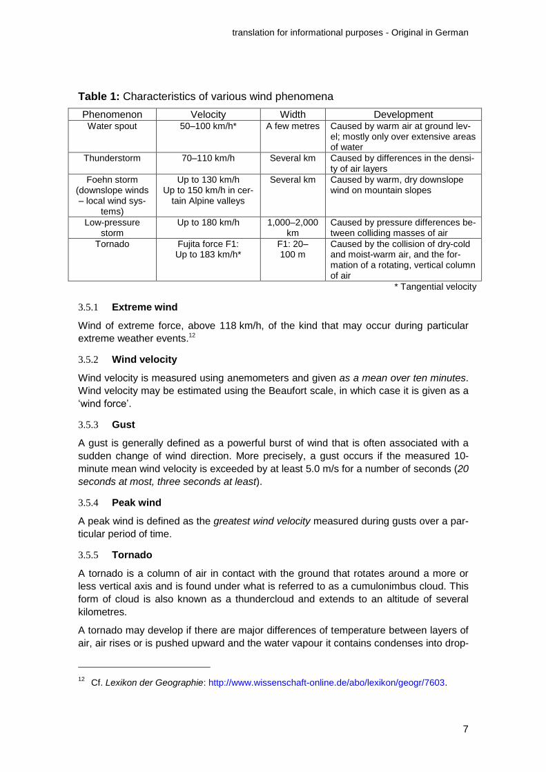
Various wind phenomena are summarised with their characteristic features in Table 1.
These wind phenomena are distinguished not only by the velocities of their peak winds,
but also by the size of the areas they affect and their duration. A low-pressure storm
affects the greatest area and lasts the longest, while tornadoes affect only relatively
small areas and are of relatively short duration.
With the phenomena detailed in Table 1 as its point of departure, DIN EN 1991-1-4
gives consideration to various actions on installations or parts of installations, e.g.
cladding units. A horizontal flow of air is assumed in the model on which it is based.
Force F1 tornadoes (cf. Table 2) are not covered by DIN EN 1991-1-4 because their
aerodynamics are different from those of other types of wind (see below). Nonetheless,
at a maximum of 183 km/h, they still fall within the range of velocities reached by low-
pressure storms, so that the horizontal wind pressures they generate are covered indi-
rectly by DIN EN 1991-1-4.
translation for informational purposes - Original in German
7
Table 1: Characteristics of various wind phenomena
Phenomenon Velocity Width Development Water spout 50–100 km/h* A few metres Caused by warm air at ground lev-
el; mostly only over extensive areas of water
Thunderstorm 70–110 km/h Several km Caused by differences in the densi-ty of air layers
Foehn storm (downslope winds – local wind sys-
tems)
Up to 130 km/h Up to 150 km/h in cer-
tain Alpine valleys
Several km Caused by warm, dry downslope wind on mountain slopes
Low-pressure storm
Up to 180 km/h 1,000–2,000 km
Caused by pressure differences be-tween colliding masses of air
Tornado Fujita force F1: Up to 183 km/h*
F1: 20–100 m
Caused by the collision of dry-cold and moist-warm air, and the for-mation of a rotating, vertical column of air
* Tangential velocity
3.5.1 Extreme wind
Wind of extreme force, above 118 km/h, of the kind that may occur during particular
extreme weather events.12
3.5.2 Wind velocity
Wind velocity is measured using anemometers and given as a mean over ten minutes.
Wind velocity may be estimated using the Beaufort scale, in which case it is given as a
‘wind force’.
3.5.3 Gust
A gust is generally defined as a powerful burst of wind that is often associated with a
sudden change of wind direction. More precisely, a gust occurs if the measured 10-
minute mean wind velocity is exceeded by at least 5.0 m/s for a number of seconds (20
seconds at most, three seconds at least).
3.5.4 Peak wind
A peak wind is defined as the greatest wind velocity measured during gusts over a par-
ticular period of time.
3.5.5 Tornado
A tornado is a column of air in contact with the ground that rotates around a more or
less vertical axis and is found under what is referred to as a cumulonimbus cloud. This
form of cloud is also known as a thundercloud and extends to an altitude of several
kilometres.
A tornado may develop if there are major differences of temperature between layers of
air, air rises or is pushed upward and the water vapour it contains condenses into drop-
12
Cf. Lexikon der Geographie: http://www.wissenschaft-online.de/abo/lexikon/geogr/7603.

translation for informational purposes - Original in German
8
lets (forming a thundercloud). The condensation heat released when this happens and,
additionally, a strong vertical wind shear (increase in radial wind velocity and, in some
cases, changes in wind direction with altitude) generate a rotating funnel of rising wind.
This may reach a diameter of up to one kilometre, while wind velocities of several hun-
dred kilometres an hour may occur. A tornado devastates a strip several hundred me-
tres wide along its track (damage (Asgards) path).
‘Tornadoes’ are also known by other names, e.g.: ‘wind spout’ (tornado over land), ‘wa-
ter spout’ (tornado over the sea or a large inland lake).
Tornadoes are classified, among other things, using the Fujita Scale, which is shown in
Table 2. Since the wind velocities given in Table 2 frequently cannot be measured,
tornadoes are often rated depending on the damage they cause to the fabric of build-
ings.
Table 2: Fujita Scale with rating by typical damage
Fujita Scale
F Scale
Rating Velocity in m/s at vmax
Velocity in km/h at vmax
Typical damage
F0 Weak (= Beaufort 8)
17.5–32.5 63–117 Light objects are swirled around, individu-al roof tiles and branches are torn down
F1 Weak 32.8–50.8 118–183 Parts of roofs are peeled off, mobile homes and trailers are overturned, strong branches are broken off, individual trees are uprooted
F2 Strong 51.1–70.5 184–254 Whole roofs are ripped off, severe dam-age to light buildings, major damage to vehicles, stable trees are toppled or bro-ken.
F3 Strong 70.8–92.8 255–334 Light buildings are overwhelmingly de-stroyed, collapse of individual buildings, heavy vehicles are overturned, extremely severe damage to woody plants with ex-tensive loss of branches
F4 Violent 93–117 335–421 Devastating damage to substantial build-ings, widespread collapse of buildings, road vehicles are thrown long distances, trees are debarked by objects flying about
F5 Violent > 117 > 421 Substantial buildings overwhelmingly damaged beyond repair, incredible dam-age, heavy objects such as road vehicles fly hundreds of metres through the air, total debarking of tree trunks that remain standing, rootstocks of felled trees are torn out of the ground
On average, approximately four tornadoes a year with an intensity greater than F1
(weak) occur in Germany. These are locally limited events that affect areas of a few
square kilometres.

translation for informational purposes - Original in German
9
3.6 Snow load
Snow load is one of the climatically induced, variable actions on installations and parts
of installations. It is influenced by the geographical location and the shape of the object
under examination. Depending on its characteristics and age, weights between
1.0 kN/m³ and 5.0 kN/m³ may be assumed when snow is lying. In the relevant stand-
ards,13 snow loads are converted into reference values used to determine the safety of
structures. The reference values specified in these standards correspond to the
98% fractiles of the annual maximums and therefore a mean return period of 50 years.
3.6.1 Exceptional snow load
An ‘exceptional snow load’ is defined as an exceptional impact pursuant to section
1.5.3.5 of DIN EN 1990 (December 2010) caused by snow loads. When structures are
planned, therefore, the partial factors associated with impacts caused by exceptional
snow loads in the context of an exceptional combination of impacts may be reduced,
and combination factors for other forms of load taken into consideration to a reduced
extent. Furthermore, when exceptional snow loads act on a structure, its complete fail-
ure must be excluded; however, localised damage to structures (for instance due to
plastic deformation) is permissible. After an exceptional snow load has acted on a
structure, a review of its integrity is therefore required before the installation is operated
further.
3.6.2 Extreme snow load
An ‘extreme snow load’ is defined as the greatest snow load at a location documented
in regionally available records.
3.7 Ice load
Ice load is defined as the additional static (weight) and dynamic (air resistance) loads
imposed on parts of installations by freezing rain or hard rime, i.e. a deposit of super-
cooled fog droplets on surfaces. Parts of installations in upland areas are particularly
threatened by frozen fog deposits. The formation of ice in this way is greatly encour-
aged by strong winds and high levels of liquid water in fog. In lowland areas, by con-
trast, ice formation usually occurs during freezing rain. Ice loads are therefore found
not only on horizontal surfaces, but may act on structures in combination with wind
loads and cause vibrations when this happens.
3.8 Wind-induced projectile
The terms ‘wind-induced projectile’ and ‘wind-induced projectile impact’ are used in the
present Technical Rule on Installation Safety. If parts of installations or objects are de-
tached or lifted by the wind and carried through the air, they are referred to as ‘airborne
projectiles’. If objects are slid or rolled along the ground by the wind, they are referred
to as ‘ground-level projectiles’. Collapsing parts of installations, trees, etc. are referred
to as other ‘wind-induced projectiles’.
13
DIN EN 1991-1-3 and DIN EN 1991-1-3/NA.

translation for informational purposes - Original in German
10
3.9 Disruption to normal operation caused by wind, snow loads and ice loads
Where the occurrence of not reasonably to be excluded gusts, peak winds, snow loads,
ice loads and secondary hazard sources, such as wind-induced projectiles, pressure
fluctuations or vibrations, leads to the design loads of safety-relevant parts of installa-
tions14 being exceeded, normal operation has been disrupted.
Disruption to normal operation of this kind is encountered, in particular, in the following
situations:
1. When the stability and/or integrity of safety-relevant parts of sites and installa-
tions where particular substances are present is immediately threatened.
2. When the functioning of safety-relevant parts of sites and installations is threat-
ened.
3. When safety-relevant operating procedures or work processes cannot be carried
out or only carried out under more difficult conditions, e.g. due to restrictions on
the accessibility of parts of sites and installations.
3.10 Protection concept
Within the meaning of the present Technical Rule on Installation Safety, a protection
concept addresses the development of suitable precautions to prevent major accidents
and measures to mitigate the effects of major accidents caused by the actuation of
environmental hazard sources.
3.11 Installation-specific protection aims
Within the meaning of the present Technical Rule on Installation Safety, installation-
specific protection aims give concrete form to the legal protection aims laid down for
sites in order to preserve human health, the environment and property from the ad-
verse consequences of a release, fire or explosion involving hazardous substances
that is caused by the actuation of an environmental hazard source. Where installations
require licencing under the Federal Immission Control Act, it must be guaranteed, pur-
suant to Article 5(1) of the Federal Immission Control Act, that
1. harmful effects on the environment and other hazards, significant disadvantages
and significant nuisances to the public and the neighbourhood cannot arise;
2. precautionary action is taken against harmful effects on the environment and
other hazards, significant disadvantages and significant nuisances, in particular
measures consistent with the state of the art.
As far as establishments are concerned, it must be guaranteed that the characteristics
and operation of an establishment’s installations are consistent with the state of the art
of safety technology.
14
See: Commission on Process Safety: Richtwerte für sicherheitsrelevante Anlagenteile (SRA) und sicherheitsrelevante Teile eines Betriebsbereiches (SRB) (KAS-1), Bonn, 2006, http://www.kas-bmu.de/publikationen/kas/KAS1.pdf.

translation for informational purposes - Original in German
11
3.12 Precondition for the occurrence of a major accident
A precondition for the occurrence of a major accident is defined as the moment/status
in the event chain subsequent to the commencement of disruption at/during which the
preconditions for the occurrence of a major accident are fulfilled. Within the meaning of
the present Technical Rule on Installation Safety, for example, snow loads and ice
loads on a tank with hazardous substances that exceed its design loads are to be re-
garded, as a rule, as disruption to normal operation as long as there is no danger of,
e.g., a substance being released. A precondition for the occurrence of a major accident
first arises if the (increasing) snow load or ice load exceeds the design load of the tank
or the static equilibrium of the tank’s construction to such an extent that this could lead
to a serious hazard or damage to property covered by section I No. 4 of part 1 of An-
nex VI to the Major Accidents Ordinance.
4 Systematic approach and structure of the present Technical Rule on Installation Safety
The operator’s obligations within the meaning of the Major Accidents Ordinance may
be fulfilled with regard to the hazard sources examined in the present Technical Rule
on Installation Safety by taking the following four steps:
1. hazard source anal-
ysis,
which involves scrutinising what hazard sources could
affect the site,
2. analysis of hazards
and threats,
which involves scrutinising whether major accidents
could occur as a result of actions on safety-relevant
parts of installations,
3. drafting of a protec-
tion concept,
which involves specifying precautions to prevent major
accidents,
4. examination of ‘ma-
jor accidents de-
spite precautions’
which leads, in particular, to the specification of
measures to mitigate the effects of major accidents.

translation for informational purposes - Original in German
12
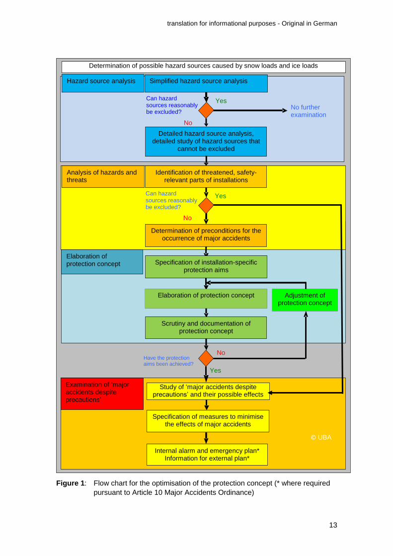
The point of departure for the systematic approach taken (cf. Figure 1) is a hazard
source analysis that involves the determination of possible hazard sources. Initially, in
a simplified hazard source analysis, only events that are possible (not reasonably to be
excluded) in the region are identified in qualitative terms at the location (incl. the estab-
lishment). In a detailed hazard source analysis, quantitative information is drawn upon
in order to determine possible hazard sources with greater precision.
The next step is to identify the safety-relevant parts of the establishment and its instal-
lations that are threatened.
Depending on their safety-relevance and the possible effects of a major accident, in-
stallation-specific protection aims are to be specified, and a protection concept elabo-
rated with which these aims are to be achieved. Once this has been done, the effec-
tiveness of the protection concept is to be scrutinised and the concept is to be docu-
mented. Where necessary, further adjustments are to be made to the protection con-
cept.
Subsequently, hazard sources that are reasonably to be excluded (‘major accidents
despite precautions’) are studied. It may not be possible to prevent the occurrence of
such accidents but, irrespective of the precautions taken to prevent major accidents
under Article 3(1) of the Major Accidents Ordinance, additional measures are to be
taken to mitigate their effects and so keep those effects as small as possible (Arti-
cle 3(3) Major Accidents Ordinance). Measures to mitigate the effects of major acci-
dents are to be incorporated into the protection concept.
Where unacceptable risks remain, in particular due to inadequate precautions for the
prevention of major accidents, more extensive precautions and measures are to be
developed in order to reduce these risks to an accepted degree.
The above does not apply to hazard sources that are so improbable as to be beyond
human experience and incalculable. No installation-specific precautions and measures
are to be taken against exceptional major accidents of this kind.
Suitable consideration is also to be given to the results obtained from the examination
of ‘major accidents despite precautions’ discussed above when plans are made for
emergencies, onsite alarm and emergency plans are amended, information is commu-
nicated for the purposes of external alarm and emergency planning, and information is
passed on concerning the siting of new activities (pursuant to No. 5 of Article 9(1) Ma-
jor Accidents Ordinance).
Hazard source analyses, and analyses of hazards and threats are to be taken into con-
sideration in concepts for the prevention of major accidents, and are to be included in
safety reports together with the studies of ‘major accidents despite precautions’ dis-
cussed above.
© UBA
translation for informational purposes - Original in German
13
Figure 1: Flow chart for the optimisation of the protection concept (* where required
pursuant to Article 10 Major Accidents Ordinance)
Determination of possible hazard sources caused by snow loads and ice loads
Simplified hazard source analysis
Can hazard sources reasonably be excluded?
Detailed hazard source analysis, detailed study of hazard sources that
cannot be excluded
No further examination
Have the protection aims been achieved?
Yes
Yes
No
Determination of preconditions for the occurrence of major accidents
Specification of installation-specific protection aims
Elaboration of protection concept
Scrutiny and documentation of protection concept
Study of ‘major accidents despite precautions’ and their possible effects
Specification of measures to minimise the effects of major accidents
Identification of threatened, safety-relevant parts of installations
Adjustment of protection concept
Internal alarm and emergency plan* Information for external plan*
Analysis of hazards and threats
Hazard source analysis
Examination of ‘major accidents despite precautions’
No
Elaboration of protection concept
Can hazard sources reasonably be excluded?
Yes
No
© UBA

translation for informational purposes - Original in German
14
5 Description of hazard sources
Events connected with the environmental hazard sources dealt with in the present
Technical Rule on Installation Safety are categorised as follows:
1. trigger events, such as wind, snowfall, freezing fog or frozen rain, that cannot be
influenced by measures and
2. possible consequent events, e.g. wind pressure, snow loads, ice loads or wind-
induced projectiles.
The systematic categorisation of various events is set out in Figure 2.
Figure 2: Systematic categorisation of hazard sources triggered by wind, snow loads and ice loads
5.1 Hazard sources caused by static and dynamic loads
In view of the higher hazard potential posed by the hazardous substances that are pre-
sent in them, safety-relevant parts of installations and establishments are to be de-
signed to withstand wind, snow loads and ice loads.
5.1.1 Hazard sources caused by wind loads
Wind, in particular in the form of gusts and peak winds, exerts pressure on installations
and parts of installations, e.g. enclosures, that is referred to as wind pressure. This is
positive on the windward side (pressure), and negative on side walls, roof surfaces and
the leeward side (suction and pressure from inside a construction work due to the pen-
etration of wind). In addition to this, wind, in particular gusts and peak winds, may ex-
cite objects to vibrate.
Tornadoes are characterised by their high rotation velocity, in addition to which there is
also the velocity at which they move forward (translation velocity). Furthermore, strong,
Trigger events, cannot be influenced, e.g.:
• Wind, including gusts • Snowfall and peak winds • Ice formation • Changes in wind pressure • Temperature fluctuations,
sometimes combined with rain
Threats caused by static and
dynamic loads
• Wind pressure (positive, negative)
• Wind-excited vibrations • Snow load • Ice load
©UBA
Threats caused by
• Wind-induced creation of projectiles
• Projectile impact • Dust • Pressure changes

translation for informational purposes - Original in German
15
upward air currents are generated, which may also lead to negative pressures that
produce vertical forces. The characteristics of a tornado therefore differ significantly
from those of the wind types covered by DIN EN 1991-1-4 with their horizontal air cur-
rents.
An overview of the various potential threats caused by wind is shown in Figure 3.
Figure 3: Potential threats caused by wind loads
In summary, a threat caused by these loads may be triggered by
1. wind pressure on the windward wall,
2. suction on the walls parallel to the wind, the roof and the leeward wall,
3. vibrations.
5.1.2 Hazard sources caused by vibrations
A flow of air may excite significant vibrations in parts of installations.
The periodic shedding of eddies, what are known as Kármán vortex streets, may make
parts of an installation vibrate. Relevant vibrations occur at the critical wind velocity at
which the eddy shedding frequency is equal to an eigenfrequency of the part of the
installation in question.
Other types of vibrations may also occur, such as the fluttering of flat parts of an instal-
lation or the interference galloping15 of cylindrical parts in close proximity to one anoth-
er.
In all these cases, the part of the installation that vibrates frequently fails due to materi-
al fatigue after a certain number of stress cycles.
15
An aeroelastic phenomenon that may occur when a fluid flows around narrowly spaced cylindrical bodies.
Negative pressure (suction)
Negative pressure (suction)
Vibrations
Gusts (dynamic load)
Wind pressure (static load)
© UBA

translation for informational purposes - Original in German
16
Finally, a sequence of gusts will also give rise to vibrations in the direction of the wind
that are usually compensated for when static calculations are carried out by applying
an appropriate multiplication factor for the gust wind load.
5.1.3 Hazard sources caused by snow loads and ice loads
Snow loads act primarily on the horizontal and sloping roofs of enclosures, installations
and parts of installations. Snow may be transformed dramatically if there are tempera-
ture changes due to thawing and freezing, and take on a higher weight density. During
periods of thaw, rain trapped in snow may greatly increase the weight of the snow.
Ice loads may form as a consequence of frozen rain or hard rime, a deposit of fog drop-
lets (primarily on the windward side of objects), and therefore also accumulate on other
surfaces. Apart from enclosures, other parts of installations, such as pipes, cable trays,
platforms, gantries and tanks, may be partially or wholly affected by these loads.
5.2 Hazard sources caused by wind-induced projectiles, air pressure chang-
es and pressure fluctuations
5.2.1 Hazard sources caused by wind-induced projectiles
Gusts and peak winds may detach inadequately secured, safety-relevant parts of in-
stallations and, by causing their loss, threaten the safety of installations and establish-
ments (Case 1: Loss of safety-relevant parts of installations).
Loose parts from the areas around installations or parts that have been detached from
installations may impact on safety-relevant parts of installations and impair their func-
tioning or integrity. Trees may be uprooted and impact on neighbouring parts of instal-
lations (Case 2: Damage to safety-relevant parts of installations).
When there are horizontally moving winds, the trajectory of an object that has been
detached is determined by a vertical speed vector and a horizontal speed vector. Ac-
cordingly, high-density objects and/or compact parts fall almost vertically to the ground,
while flat objects with low densities may be carried away by the wind (airborne projec-
tiles). Apart from the object’s properties and the wind velocity, the length of its trajecto-
ry is determined by the height at which it was originally located.
Further to this, heavy objects may be moved across the ground (sliding or rolling) and
impact on other parts of installations at ground level (ground-level projectiles).
The detachment of parts of installations and the threats caused by wind-induced pro-
jectiles are summarised in for horizontally acting streams of air.

translation for informational purposes - Original in German
17
Figure 4: Potential threats caused by the detachment of objects, wind-induced pro-
jectiles and negative pressure due to suction
5.2.2 Hazard sources caused by air pressure changes and pressure variations
Air pressure changes, pressure and suction during windy conditions, gusts and peak
winds in particular, may bring about deformations in containers with flexible skins (e.g.
inflatable gas holders at biogas plants). Gusts and peak winds may act on emissions
sources and, by giving rise to pressure or suction, cause pressure changes in connect-
ed parts of installations. Pressure fluctuations of this kind may trigger and/or alter flows
of substances in installations, e.g. in waste gas or ventilation systems. It is therefore
also to be appraised whether, in view of the characteristics and operation of the instal-
lations in question, changes in air pressure and pressure fluctuations caused by inflow-
ing air could be safety-relevant in any way.
6 Simplified hazard source analysis
While flooding may reasonably be excluded as a hazard source for particular regions
as early as the ‘simplified hazard source analysis’, this is not possible for wind, snow
loads and ice loads. However, the scale of the threat differs from one region to another.
In consequence, hazard maps have been drawn up16 (although not for tornadoes) that
form the foundations for a detailed hazard source analysis.
The appraisal of the hazards caused by tornadoes in Germany is difficult. Unlike in the
USA or Switzerland, no validated hazard map for tornadoes has been drawn up for
Germany to date so that no grading of regional hazard levels analogous to the wind,
snow load and ice load zone maps is available to the operator of an installation. How-
ever, this does not mean there is no risk of tornadoes in Germany and this risk there-
fore does not have to be examined.
16
Cf. DIN EN 1991-1-3/NA, DIN EN 1991-1-4/NA and DIN 1055-5.
Negative pressure (suction)
Object detached
Light, flat objects
Heavy objects
Airborne projectiles
Ground level projectiles
© UBA

translation for informational purposes - Original in German
18
Nonetheless, the frequency with which an establishment could be hit by a tornado is far
below the frequency taken as the basis for the analysis of wind, snow loads and ice
loads as hazard sources (100-year return period). This means the occurrence of torna-
does is reasonably to be excluded. Although tornadoes are described as a hazard
source in the present Technical Rule on Installation Safety, no further guidance is
therefore to be given for installation-specific protection aims and protection concepts.
However, possible actions of tornadoes should be taken into consideration by
examining more extensive event scenarios, as well as the measures derived from them
both to mitigate the effects of major accidents, and in the context of alarm and
emergency planning (cf. section 13).
Nor is it possible, as a matter of principle, to reasonably exclude ‘wind-induced projec-
tiles’, and this hazard source must be subjected to a detailed hazard source analysis.
As far as pressure changes and fluctuations are concerned, it is to be scrutinised
whether, in view of the characteristics and operation of the installations in question, a
change in air pressure and pressure fluctuations caused by inflowing air could be safe-
ty-relevant in any way. If this is not the case, it is possible to do without a detailed haz-
ard source analysis.
7 Detailed hazard source analysis
A detailed hazard source analysis is required for situations in which it is not possible to
reasonably exclude hazard sources. Since the failure of safety-relevant parts of instal-
lations within the scope of the Major Accidents Ordinance may give rise to a major ac-
cident, a 100-year event is taken as the basis – in part by analogy to TRAS 310 – for
hazard sources that are not reasonably to be excluded. As the essential foundations for
this approach, reference is made in the present Technical Rule on Installation Safety to
the DIN EN standards developed for the relevant hazard sources (see below) and DIN
1055-5 for ice loads. These include hazard maps for natural events (cf. the national
annexes to the DIN EN standards). They are based on statistical evaluations of past
events. In these documents, the characteristic parameters of each hazard source are
given for 50-year events. In line with the approach taken in the DIN EN standards, with-
in the scope of the present Technical Rule on Installation Safety the values for loads
are ‘adjusted’ to correlate to a 100-year return period not by altering these parameters,
but by increasing the partial factor for the actions in question at installations with higher
hazard potential, as already provided for in DIN EN 1990.
7.1 Static and dynamic loads
7.1.1 Relationship to standards and reliability classes
The foundations for hazard source analyses are, in particular, DIN EN 1991-1-4 for
wind, DIN EN 1991-1-3 for snow loads (in each case in combination with the relevant
national annexes) and DIN 1055-5 for ice loads. Due to the grave consequences of any
failure of safety-relevant parts of an installation or site, they are to be designated in
reliability class RC 3 and consequences class CC 3 in accordance with the provisions
set out in Annex B to DIN EN 1990 and DIN EN 1990/NA (December 2010), e.g. like
places of assembly. It follows from this designation that the partial factor for these ac-

translation for informational purposes - Original in German
19
tions is to be increased by applying the factor KFI = 1.1 (see also section 1.3.1 of An-
nex A to DIN EN 1990/NA). This raises the protection aim of the standards from a 50-
year event to a 100-year event. (For further discussion of this point, see section 10
below.)
Installations and parts of installations with this designation, in particular structures, are
to be reviewed in the course of the hazard source analysis for wind, snow loads and ice
loads (see section 10 below).
Where the hazard potential is particularly high, it is to be scrutinised when installation-
specific protection aims are being specified whether there is a need for the application
of further-reaching partial factors (as set out in to the note to Table B2 of Annex B to
DIN EN 1990).
Furthermore, attention is to be paid to the fact that, apart from the obligation to take
precautions for major accidents on the basis of obligations to ensure liability for prem-
ises, any threat to people due to, e.g., the failure of structures or projectiles must be
excluded.
7.1.2 Wind loads
Account is taken of the requirements of the present Technical Rule on Installation
Safety by increasing the partial factor, as explained above, which is done by applying
the multiplication factor KFI = 1.1, i.e. the partial factor is increased from 1.5 to 1.65 (for
further details, see section 10 below).
7.1.3 Snow loads and ice loads
Pursuant to Annex D to DIN EN 1991-1-3, in order to meet the requirements of the pre-
sent Technical Rule on Installation Safety, an increase by approx. 10% may be
calculated using the Gumbel probability distribution posited as a basis for the relevant
formula. Account is taken of the rise in the return period by increasing the partial factor,
which is multiplied by the factor KFI = 1.1, i.e. from 1.5 to 1.65 (for further details, see
section 10 below).
Accidental snow loads are to be taken into consideration as exceptional actions cov-
ered by DIN EN 1990. Where the competent authority has specified reference values
for this purpose, pursuant to part 4.3 of DIN EN 1991-1-3/NA, use is to be made of
these reference values. Where no reference values of this kind have been specified by
the competent authority (as may be the case, in particular, away from the North Ger-
man Plain), use is to be made of data on extreme snow loads that have been recorded
in the region.
When the load assumptions for the European Standard concept were revised, there
was no revision of the load assumptions for ice loads (caused by frozen rain and hard
rime). Ice loads are not given consideration in DIN EN 1991-1-3. As far as such loads
are concerned, DIN 1055-5, with its informative Annex A, reflected the state of the art.
When the Eurocodes were introduced, this part was dropped without being replaced so
that no detailed data on ice loads are to be found (any longer) in the construction
standards. Of course, this does not mean that these loads do not exist. Since ice loads
are to be examined in the hazard source analysis, DIN 1055-5 should continue to be

translation for informational purposes - Original in German
20
used as a source of information for this purpose, with attention being paid to the re-
marks made above, until such time as the DIN EN standard has been amended to cov-
er ice loads.
7.2 Consideration of climate change
When a hazard source analysis is carried out, consideration is to be given to the antici-
pated consequences of climate change, even though it is in their nature for them to be
affected by uncertainties. It is to be assumed that the changes in the climate that have
already occurred are having an influence on the intensity and frequency with which at
least some of the hazard sources discussed above are actuated.
However, no adequate information is available with regard to changes to the hazard
sources wind, snow loads and ice loads that are being driven by climate change (cf.
section 1 above). For this reason, no climate change factors may be given for the loads
discussed above at present.17
7.3 Wind-induced projectiles
If installations or parts of installations do not withstand the static or dynamic loads de-
scribed above, they may collapse or overturn, or projectiles may be detached and cre-
ated (‘internal creation of projectiles’). The same applies for installations that may
neighbour the site. Similar processes also affect features that are not construction
works, e.g. trees (‘external creation of projectiles’).
As experience with wind-induced projectiles has shown, the possible hazard sources
may be summarised as follows:
7.3.1 Loss of safety-relevant parts of installations
The loss of parts of installations may be safety-relevant in itself.
7.3.2 Damage to safety-relevant parts of installations
As a matter of principle, safety-relevant parts of installations may be threatened by
wind-induced projectiles (cf. section 5.2.1). Where only their collapse or overturning is
relevant, the area threatened is mostly easy to identify. As far as airborne projectiles
are concerned, the threat depends on the projectile’s path, the impact conditions and
the material of the potentially affected safety-relevant part of the installation. It is possi-
ble to estimate trajectories and the consequences of an impact for idealised ‘model
projectiles’.
Gust velocities that lie above 1.1 times the velocities detailed in DIN EN 1991-1-4 are
reasonably to be excluded as causes for the creation and movement of projectiles.
17
As at June 2015.
translation for informational purposes - Original in German
21
8 Determination of threatened, safety-relevant parts of estab-lishments and installations
The safety-relevant parts of the establishments and installations in question are
1. installations and parts of installations where particular substances and volumes
are present,
2. installations and parts of installations with particular functions
(see also KAS-118 and the BMUB’s Guide to the Enforcement of the Major Accidents Or-
dinance).
Threatened installations and parts of installations within the meaning of the present
Technical Rule on Installation Safety are safety-relevant installations and parts of
installations in which a hazard and/or threat may arise due to a major accident (hazard
and/or threat on the site or for the surrounding area) when the environmental hazard
sources in question (i.e. threats from the surrounding area) are actuated. The specific
installations and parts of installations to be protected are therefore dependent on the
kind of hazard source and its presumed intensity.
In so far as safety reports have been drawn up for existing establishments, safety-
relevant installations and parts of installations have already had to be determined for
this purpose. The installations and parts of installations determined are to be reviewed
if, the hazard source in question could act on more than one installation where the
same substance or group of substances, pursuant to Annex I of the Major Accidents
Ordinance, is present.
Not all safety-relevant parts of a site and its installations are threatened by the
hazard sources dealt with in the present Technical Rule on Installation Safety.
The expert delimitation of threatened parts of sites and installations is therefore
accorded a high degree of significance. Corresponding guidance is given below
in order to ensure that the delimitation undertaken here is meaningful.
8.1 Hazard sources caused by static and dynamic loads
8.1.1 Wind loads
On the basis of the safety-relevant parts of installations already determined pursuant to
KAS-1,19 those parts of establishments and installations are to be determined that are
threatened by wind loads (gusts or vibrations).
Attention is to be paid to the following guidance on the identification of the parts in
question:
18
Commission on Process Safety: Richtwerte für sicherheitsrelevante Anlagenteile (SRA) und sicherheitsrelevante Teile eines Betriebsbereiches (SRB) (KAS-1), Bonn, 2006, http://www.kas-bmu.de/publikationen/kas/KAS1.pdf.
19 Cf. Commission on Process Safety: Richtwerte für sicherheitsrelevante Anlagenteile (SRA)
und sicherheitsrelevante Teile eines Betriebsbereiches (SRB) (KAS-1), Bonn, 2006, http://www.kas-bmu.de/publikationen/kas/KAS1.pdf.

translation for informational purposes - Original in German
22
1. The threat to safety-relevant parts of installations in construction works that
have been constructed in accordance with DIN EN 1990 to meet the require-
ments of RC 3 may be categorised as low. Where the hazard potential is par-
ticularly high, it is to be scrutinised whether there is a need to apply further-
reaching partial factors (cf. the note to Table B2 of Annex B to DIN EN 1990).
2. If construction works have not been constructed in accordance with DIN EN
1990 to meet the requirements of RC 3 or if they are light buildings, any threat
to parts of installations accommodated in them is to be scrutinised.
3. Any threat to safety-relevant parts of installations that are located completely
underground is to be excluded.
4. Safety-relevant parts of installations that are located outdoors without enclo-
sures are potentially threatened.
8.1.2 Snow loads and ice loads
As a matter of principle, snow loads and ice loads may affect all parts of installations
that are located outdoors. Particular attention is to be paid to areas and/or parts of in-
stallations below the higher parts of installations on account of snowdrifts, snow slips or
accumulations of snow.
The operator should use a site plan to categorise the parts of installations affected to a
particular degree in terms of the level of threat to which they are exposed.
The following restrictions may be taken into consideration when the affected parts of
installations are being selected:
1. If the temperature of the building and/or shell of the installation is permanently
higher than 0 °C on account of internal processes, it is possible to do without a
detailed examination.
2. If the parts of an installation have been designed and/or reviewed pursuant to
the current standard, DIN EN 1990, with consideration being given to the high
reliability class RC 3, the level of hazard may be categorised as low.
8.2 Hazard sources caused by wind-induced projectiles: determination of
threatened installations and parts of installations
Every installation operator must prevent it from being possible for parts of buildings or
installations to be detached as a result of gusts or peak winds and become airborne
projectiles. This obligation also covers trees/branches on the site. It serves, firstly, to
protect people as required by the obligation to ensure liability for premises, and for the
purposes of occupational health and safety. Secondly, within the scope of the Major
Accidents Ordinance, safety-relevant parts of installations are also to be protected,
irrespective of whether there is a direct threat to people at the same time.
‘Wind-induced projectiles’ should therefore be studied systematically as a hazard
source. To this end, an approach is set out below that has proved its worth in the con-
text of building management. Other, equivalent approaches may also be applied. This
systematic approach is based on the following elements:
translation for informational purposes - Original in German
23
1. Regular reviews tailored to the installation’s status and hazard potential
2. Assessment of the shortcomings found and specification of effective measures
3. Implementation of measures within the prescribed time frame
Where necessary, compensatory measures to secure threatened areas
4. Where necessary, adjustment of the frequency with which reviews are carried
out
When reviews are conducted (Step 1), potential sources for wind-induced projectiles
are to be determined, preferably by means of on-the-spot checks. Apart from possible
on-site projectile sources, consideration is also to be given to the area immediately
around the site (e.g. trees on the edge of the compound, nearby installations and infra-
structure facilities).
For example, the following are to be examined as potential projectile sources:
a) Parts of installations that are not firmly secured (e.g. parts of gantries, sheet-
metal cladding units).
b) Non-built features, e.g. trees that could fall over in gusts or peak winds and
impact on safety-relevant parts of installations.
c) Open storage areas, e.g. with containers, spare parts, barrels, etc. that could
be carried away by wind.
To begin with, it is to be scrutinised whether the potential projectiles identified include
parts of installations whose loss would be safety-relevant.
Subsequently, it is to be scrutinised whether, in view of the distances from safety-
relevant parts of installations at which projectiles could be created and the kinds of pro-
jectiles that could be created, actions on parts of safety-relevant installations that would
disrupt their functioning could not reasonably be excluded either.
Possible measures to prevent the creation of wind-induced projectiles (Steps 2-4) are
described in section 11 below. If a threat to safety-relevant parts of installations from
wind-induced projectiles is, nevertheless, not excluded, it may be presumed that,
where they consist of solid, ductile material, e.g. many pressure vessels, or are pro-
tected by solid walls, e.g. made of reinforced concrete, safety-relevant installations or
parts of installations are, as a general rule, not threatened by wind events that are not
to be excluded under the present Technical Rule on Installation Safety. By contrast, if
safety-relevant installations or parts of installations are less robust and resistant to me-
chanical damage, and are not protected in other ways (e.g. enclosures), a threat is not
to be excluded.
9 Determination of the preconditions for the occurrence of major accidents
Not every actuation of a hazard source that acts on the installations and parts of instal-
lations, such as structures, that are relevant pursuant to section 8 above and identified
within the meaning of the present Technical Rule on Installation Safety will actually give
rise to a serious hazard. When the preconditions for the occurrence of major accidents

translation for informational purposes - Original in German
24
are determined, it is therefore to be scrutinised in relation to the individual safety-
relevant parts of installations and safety-relevant parts of a site whether, given the pre-
sumed types of hazard sources and the intensity with which the hazard sources in
question would be actuated in the specific instance, a major accident could really occur
or whether there would only be disruption to the operation. To this end, it is to be stud-
ied how the actuation of the hazard source could affect the safety-relevant parts of the
installations and the site threatened in each particular case.
The following procedure is proposed for the further delimitation of the parts of sites and
installations that are threatened within the meaning of the present Technical Rule on
Installation Safety:
1. determination of the effects on threatened parts of installations where particu-
lar substances and volumes are present,
2. determination of the effects on threatened parts of installations with particular
functions (within installations),
3. determination of the effects on threatened installations where particular sub-
stances and volumes are present,
4. determination of the effects on threatened installations with particular functions
inside and outside the establishment,
5. determination of the effects on the site.
At the latest when it comes to the final step, the consequences of the simultaneous
action of hazard sources on all the site’s installations and parts of installations, and
their interactions (when an action on an installation/part of an installation triggers a ma-
jor accident in another installation/part of an installation) are to be examined.
Examples of scenarios for the determination of the preconditions for major accidents:
1. Extreme wind:
a) overturning and rolling of unsecured barrels and tanks,
b) detachment of tanks or containers from their anchorings with damage to the connecting pipes (change of position),
c) pipe rupture caused by vibrations,
d) damage to floating roofs caused by wind-induced vibrations,
e) change of pressure and pressure fluctuations in waste gas systems,
f) damage to buildings and/or parts of buildings,
g) breakdown of the supply of inputs,
h) breakdown of communications links.

translation for informational purposes - Original in German
25
2. Extreme snow loads and ice loads:
a) collapse of roofs or parts of buildings,
b) interruption of supply lines on and off the site, e.g.
i. power supply,
ii. process control engineering,
iii. pipes for means of production,
iv. other safety equipment, e.g. communications equipment,
v. formation of ice on pipes and pumps.
3. Wind-induced projectiles:
a) puncturing of tanks, containers or reaction vessels for hazardous substanc-es made of thin-walled materials and/or materials that are insufficiently me-chanically robust (e.g. plastic sheeting or glass),
b) rupture of pipes,
c) damage to pumps, valves, and measurement and control equipment,
d) constraints on the functioning, or breakdown, of parts, of installations and supply facilities on and off the site, e.g.
i. power supply,
ii. process control engineering,
iii. pipes for maens of production,
iv. other safety-related equipment, e.g. communications equipment.
10 Specification of installation-specific protection aims
Installation-specific protection aims are to be drafted on the basis of what is known
about possible hazard sources (section 7 above, ‘Detailed hazard source analysis’) and
the hazards and/or threats they make possible (section 9 above, ‘Determination of the
preconditions for the occurrence of major accidents’).
Requirements for the drafting of protection aims:
1. The design of safety-relevant parts of installations, safety-relevant parts of a site
and construction works in which safety-relevant installations or parts of installa-
tions are operated in accordance with DIN EN 1990 to meet the requirements of
reliability class RC 3, which corresponds to a design to withstand a 100-year
event. Where the hazard potential is particularly high, it is to be scrutinised
whether there is a need for the application of further-reaching partial factors (cf.
the note to Table B2 of Annex B to DIN EN 1990).
2. The monitoring of the planning and construction of new, safety-relevant parts of
installations, safety-relevant parts of a site and construction works in which
safety-relevant installations are operated to meet the requirements of the design

translation for informational purposes - Original in German
26
supervision level DSL 2 and the inspection level IL 2 defined in DIN EN
1990/NA. Where the hazard potential is particularly high,20 it is to be scrutinised
whether there is a need for the application of DSL 3 and/or IL 3 design supervi-
sion and inspection measures. This requirement does not apply to existing in-
stallations and parts of installations because the monitoring of planning and
construction activities in accordance with DSL 3 or DSL 2 and IL 3 or IL 2 is on-
ly feasible retrospectively to a certain extent, if at all.
3. Design of safety-relevant parts of installations, safety-relevant parts of a site
and construction works in which safety-relevant installations are operated to
withstand the gusts, peak winds and vibrations detailed in DIN EN 1991-1-4/NA
and meet the more stringent requirements imposed by indent 1 above.
4. Design of safety-relevant parts of installations, safety-relevant parts of a site
and construction works in which safety-relevant installations are operated to
withstand the snow loads detailed in DIN EN 1991-1-3/NA and meet the more
stringent requirements imposed by indent 1 above and, in addition to this, to
withstand exceptinal snow loads on the basis of reference values specified for
this purpose by the authorities or, if such reference values are not available, ex-
treme snow loads that have occurred in the region previously.
5. Design of safety-relevant parts of installations, safety-relevant parts of a site
and construction works in which safety-relevant installations are operated to
withstand the ice loads detailed in DIN 1055-5 and satisfy the more stringent
requirements imposed by indent 1 above.
6. Monitoring of parts of construction works that are safety-relevant or in which
safety-relevant parts of installations are operated in accordance with VDI Guide-
line 6200.21
7. Steps to secure safety-relevant parts of installations and safety-relevant parts of
a site, and prevent the creation of projectiles (loss of parts of installations).
8. Protection of safety-relevant parts of installations and safety-relevant parts of a
site against projectile impact (damage to parts of installations caused by air-
borne, ground-level and other projectiles).
The following applies to existing installations and parts of installations, i.e. for which a
licence was issued prior to the publication of the present Technical Rule on Installation
Safety:
a) Evidence is to be provided that the requirements discussed above (indents 1, 3, 4
and 5 above, in particular design to withstand 100-year events) are satisfied. The
Commission on Process Safety considers it appropriate for this to be done within
a period of five years following the publication of the present Technical Rule on
Installation Safety. This evidence is to be provided in relation to the actions
20
E.g., if the part of the installation itself reaches or exceeds the quantitative thresholds set in Column 5 of the table in Annex I to the Major Accidents Ordinance.
21 VDI Guideline 6200: Structural safety of Buildings: Regular inspections (February 2010).

translation for informational purposes - Original in German
27
detailed in DIN EN 1991 and DIN 1055-5 for ice loads with the application of the
factor KFI = 1.1 (in order to allow for 100-year events) (as required for RC 3
pursuant to DIN EN 1990). Methodologically, however, the calculations may also
be carried out in compliance with the standards that applied at the time when a
license was last issued.
b) With regard to installations due to undergo alterations that will have significant ef-
fects on structural safety (e.g. corresponding changes of use, changes to the
main load-bearing construction, including integral stiffening systems, etc.), it is
necessary for the evidence to be provided in accordance with currently valid
standards.
c) When alterations are made that are significant under the Federal Immission Con-
trol Act and do not significantly affect structural safety, if at all (e.g., do not involve
alterations to the main load-bearing construction, including integral stiffening sys-
tems), the provision of the evidence stipulated by indent a) above is not required
additionally.
d) Situations may arise in which the evidence stipulated by indent a) above cannot
be provided for older installations, in particular because
i. the person appointed to scrutinise the matter does not find sufficient docu-
ments or
ii. the original calculations are based on older standards and/or other technical
building regulations that are not suitable for this scrutiny (section 3(3) of VDI
Guideline 6200).
In these cases, an initial inspection under VDI Guideline 6200 (see, in particular,
section 6, ‘Existing structures’) or an at least equivalent procedure is to be con-
ducted by a particularly expert individual in accordance with section 11 of VDI
Guideline 6200. In particular, when this is done, it is to be scrutinised whether the
load tolerances given by the standards used for the original design are still practi-
cable (e.g. inspection of load-bearing parts of installations to ascertain their integ-
rity) and fulfil the protection aim set in indent a) above. If this is the case, the op-
erator has to take organisational safety measures so that the permissible im-
posed loads are complied with on the site, with the consequence that the load
tolerances continue to be maintained. The practicability of load tolerances must
also be dealt with by regular inspections and targeted inspections following inci-
dents in which structures have been exposed to particular loads (e.g. high snow
loads, hurricanes).
If the load tolerances discussed above are no longer practicable, the inspector
has to inform the operator without delay about the necessary consequences (sec-
tion 10.1.3 of VDI Guideline 6200).
e) If the evidence required by indent a) above cannot be provided – even by an in-
spection pursuant to indent d) above –, an upgrade (adaptation to the state of the
art of safety technology) must be carried out (cf. section 10.2.1 of VDI Guideline
6200). The Commission on Process Safety considers it appropriate for this to be

translation for informational purposes - Original in German
28
done within a period of ten years following the publication of the present Tech-
nical Rule on Installation Safety.
11 Elaboration of protection concepts
Protection concepts are to be developed on the basis of the hazard sources that are
not reasonably to be excluded, the hazards and/or threats that are identified and the
protection aims. When protection concepts are elaborated, attention is to be paid to the
requirement laid down in Article 3(4) of the Major Accidents Ordinance that they be
consistent with the state of the art of safety technology.
When a protection concept is elaborated, the following points are of contributory signifi-
cance alongside the intensity of an event:
1. the speed with which the event occurs,
2. the advance warning time (e.g. weather forecast) and
3. the parties’ capacity to take effective action during the event.
This relates, in particular, to organisational measures, e.g. the relocation of hazardous
substances to safe facilities, steps taken to secure loose parts of installations, addition-
al protection for parts of installations or the timely shut-down of installations or parts of
installations.
The main protective technical measures that may be taken into consideration when a
protection concept is elaborated are construction measures:
1. Construction measures against extreme winds include, e.g.
a) the design of safety-relevant installations and parts of installations to with-stand the wind loads detailed in DIN EN 1991-1-4 and so meet the require-ments of reliability class RC 3,
b) corresponding application to non-built features,
c) enclosures for threatened parts of installations,
d) steps to secure parts of installations that represent potential on-site sources for the creation of projectiles, debris, e.g. chimneys, ventilation filters, etc.,
e) completely underground configuration of safety-relevant installations or parts of installations, where this is compatible with the requirements of monitoring, maintenance and water pollution control.
2. Construction measures against wind-excited vibrations include, e.g.,
a) aerodynamic measures to disrupt the flow forces that trigger vibrations,
b) structural measures such as vibration dampers, guy cables, frequency detun-ing systems.

translation for informational purposes - Original in German
29
3. Construction and organisational measures against snow loads and ice loads in-
clude, e.g.,
a) the design of safety-relevant installations and parts of installations to with-stand the snow loads and ice loads detailed in DIN EN 1991-1-3 and/or DIN 1055-5 subject to the application of reliability class RC 3 and considera-tion of accidental loads,
b) corresponding application to non-built features,
c) to supplement these measures, the measurement of snow loads with sen-sors, with roofs being cleared once a particular load is reached (organisa-tional measure).
4. Measures against projectiles include, e.g.,
a) regular awareness-raising and instruction for employees concerning the possible consequences of projectiles and their obligations to prevent projec-tiles being created,
b) inspection of the site compound, with particular attention being paid to po-tential sources for the creation of projectiles; inspections to be carried out regularly and when storm warnings are received,
c) assessment of shortcomings that are found and determination of effective measures if safety cannot be guaranteed until the next inspection. These include, e.g., the following measures:
i. replacement of the fastenings for inadequately secured parts of instal-lations,
ii. installation of additional load-bearing and/or stabilising structures, where necessary,
iii. installation of debris nets to protect against parts of facades that fall down,
iv. additional fencing off of threatened areas, where necessary,
v. installation of crash barriers,
vi. steps to secure or remove trees if safety-relevant parts of installations are located in the area that would be affected and might be hit if the trees fell over.
These measures are to be taken in order to ensure that the creation of pro-jectiles is reasonably to be excluded as the cause of a major accident.
d) Implementation of measures within the prescribed period of time or com-pensatory measures to bridge over the period until the implementation of measures. These compensatory measures include, e.g.,
i. the reduction of the floor load until additional load-bearing elements are installed,
ii. steps to secure trees against falling over using firmly anchored ca-bles.

translation for informational purposes - Original in German
30
Under certain circumstances, it may be necessary to adjust the frequency with which
inspections are carried out in order to keep an eye on the development of damage over
time and, where necessary, be able to take the requisite measures promptly as well.
12 Scrutiny of protection concepts
The protection concept developed pursuant to Section 11 is to be reviewed to ascertain
whether the protection aims have been achieved. When this is done, consideration is to
be given to the intensity of the environmental hazard sources, and the probabilities of
failure for the precautions and risk-reduction measures that have been chosen.
This study is used to provide evidence that the operator’s obligations pursuant to the
Major Accidents Ordinance and the Federal Immission Control Act are being fulfilled.
If the precautions and measures chosen are found not to be sufficient, the protection
concept in question is to be revised in order to incorporate further precautions against
major accidents.
If the precautions are sufficient, the steps taken to date, in particular the protection
aims, protection concepts and their scrutiny, are to be documented, with attention being
paid to the relevant requirements of the Major Accidents Ordinance and the Federal
Immission Control Act.
13 Determination of scenarios pursuant to Article 3(3) of the Major Accidents Ordinance (‘major accidents despite pre-cautions’) and scenarios for alarm and emergency planning
These scenarios are determined in order to identify
1. the measures required to keep the effects of major accidents that are reasona-
bly to be excluded as small as possible pursuant to Article 3(3) and Article 5(1)
of the Major Accidents Ordinance (‘major accidents despite precautions’), and
point 2 of section 9.2.6.2.3 of the BMUB’s Guide to the Enforcement of the Major
Accidents Ordinance),
2. the information required for the elaboration of internal alarm and emergency
plans (pursuant to Article 10 Major Accidents Ordinance), and
3. the information required for the drafting of external alarm and emergency plans
(pursuant to point 4 of Article 9(1) Major Accidents Ordinance and point 3 of
section 9.2.6.2.3 of the BMUB’s Guide to the Enforcement of the Major Accidents
Ordinance).
Hazard sources that are reasonably to be excluded and could give rise to ‘major acci-
dents despite precautions’ may include, e.g.,
1. the failure of precautions taken under Article 3(1) of the Major Accidents Ordi-
nance,
2. extreme winds above a reasonably to be presumed intensity and tornadoes of
forces up to and including F4 that, by their nature, are not reasonably to be pre-
sumed,

translation for informational purposes - Original in German
31
3. snow loads and ice loads above a reasonably to be presumed intensity.
This means that, in particular where a substance is released due to hazard sources
that are reasonably to be excluded, additional measures are to be taken in order to
keep the harmful effects on humans, the environment and property as small as possi-
ble.
However, hazard sources that are reasonably to be excluded may also be so improba-
ble as to be beyond human experience and incalculable. No installation-specific pre-
cautions are to be taken against exceptional major accidents of these kinds. This ap-
plies, e.g., for force F5 tornadoes of which, as far as is known at present, no definite
evidence has been provided to date in Germany. Under these conditions, their consid-
eration would not be expedient when the effects of major accidents are being exam-
ined.
As a matter of principle, the hazard sources examined in the present Technical Rule on
Installation Safety may lead to the secure containment of hazardous substances no
longer being guaranteed. In consequence, as a minimum, the release of the largest
coherent mass of a hazardous substance within the meaning of the Major Accidents
Ordinance is to be assumed, irrespective of its cause.
Alternatively, the operator may, e.g., be guided by:
a) historic events,
b) the maximum peak winds that have occurred (in so far as it is possible for them
to be determined).
In particular, attention is to be paid to the following points when scenarios are set out:
1. Environmental hazard sources, e.g. tornadoes, extreme winds and snow loads,
are extensive events and may therefore act on several parts of an installation
simultaneously, causing disruption.
2. In consequence, it is to be scrutinised whether more than the largest coherent
mass could be released (e.g. failure of several tanks).
3. It is to be assumed that the feasibility of the measures to mitigate the effects of
major accidents provided for to date where environmental hazard sources arise
will be limited in certain circumstances (if it is not possible to go outdoors, ac-
cess routes are blocked, etc.).
4. In addition to this, it is to be assumed that the availability of external personnel
will be limited.
5. Furthermore, the extent to which disruption may trigger further disruption at a
different installation or different part of the same installation is to be scrutinised.
14 Specification of measures to mitigate the effects of major accidents
According to Article 3(3) of the Major Accidents Ordinance, in order to fulfil its obliga-
tions, the operator has to take precautionary measures to keep the effects of major
accidents as small as possible. Suitable technical and organisational measures are set

translation for informational purposes - Original in German
32
out in the following sections. When technical measures are taken to mitigate the effects
of major accidents, two fundamental options are to be distinguished:
1. Measures that take effect immediately at the affected site, installation or part of
an installation (e.g. oil depots, pipes) in order to minimise the release of haz-
ardous substances,
2. Measures that take effect around the affected site in order to prevent and/or mit-
igate the dispersion of substances.
Whether, and to what extent, the external, environmental hazard sources examined in
the present Technical Rule on Installation Safety permit measures to be taken to
prevent the dispersion of contaminants in the first place must be scrutinised
systematically in the individual case. When wind events occur, it may be impossible for
people to go outdoors because this would be life-threatening. The icing of internal
roads may also be regarded as a hazard source. If these roads ice up and, as a result,
there is a danger of vehicles not being able to drive on the them safely and potentially
colliding with safety-relevant parts of installations, this hazard source is to be excluded,
e.g. by means of ice-clearance measures.
Apart from the site that is affected, the area immediately around the establishment may
also be affected and the hazard source may last for a long time. This is to be taken into
consideration in the alarm and emergency plan (see section 16.2).
It is to be scrutinised whether protection concepts previously developed in the safety
report cover the scenarios for the release of substances, fire and explosion in any
event, and whether the measures to mitigate the effects of major accidents provided for
here, where necessary, are sufficient.
It is possible to mention the following as examples of specific guidance on measures to
mitigate the effects of major accidents within the scope of the present Technical Rule
on Installation Safety:
1. Safety equipment and protective precautions:
a) buffer areas,
b) protective walls or embankments,
c) quick-closing mechanisms.
2 Consideration of the threats caused by wind, snow loads and ice loads in the
site’s alarm and emergency organisation.
3. Consideration of the threats caused by wind, snow loads and ice loads in the
deliberations conducted by the authorities responsible for preventing hazards
and the emergency services when a major accident occurs (Article 5(2) Major
Accidents Ordinance).

translation for informational purposes - Original in German
33
15 Planning for emergencies, amendment of site alarm and emergency plans, communication of information for exter-nal alarm and emergency planning
15.1 Planning for emergencies
Pursuant to Article 8(3) of the Major Accidents Ordinance, in the cases covered by
points 1 to 3 of Article 7(2) of the Major Accidents Ordinance, the operator has to re-
view and, where necessary, update the concept for the prevention of major accidents,
including the safety management system on which this concept is based, as well as the
procedures for its implementation. In consequence, this provision also relates to the
planning for emergencies required by section (3)(e) of Annex III to the Major Accidents
Ordinance. The results of the above steps are to be taken into consideration when the
concept is updated.
15.2 Amendment of site alarm and emergency plans
Under Article 10 of the Major Accidents Ordinance, the operator of an establishment
that is subject to extended obligations has to draw up an alarm and emergency plan
and, under Article 10(4) of the Major Accidents Ordinance, test, review and update that
plan. Establishments with standard obligations may also be obliged to draw up plans of
this kind in accordance with an order issued in the individual case (Article 1(2) in con-
junction with Article 6(4) Major Accidents Ordinance).
When the alarm and emergency plan is drawn up, consideration is also to be given to
equipment that is not located on the site compound and is not part of the site, e.g.
overhead cables, masts with communications equipment, but where the loss of its func-
tionality as a consequence of wind loads could affect the site as an external hazard
source. Infrastructure facilities such as roads and railway tracks are also to be exam-
ined so that consideration can be given to their functions in the alarm and emergency
plan as well.
It is to be taken into consideration that disruption of this kind may last for a long period
of time. This applies, above all, for extensive low-pressure storms, as well as heavy
snow loads and ice loads, which may restrict the use of, or even completely block, the
infrastructure around the affected site. Such disruption includes:
1. Destruction of overhead power lines off-site
Overhead power lines may be destroyed, firstly, by storms/tornadoes and, secondly, by
icy precipitation in combination with strong winds. When this happens, either the masts
are directly snapped by the wind load or, if there is heavy frozen rain, the power lines
are loaded beyond their critical load by clinging ice. This may give rise to localised or
even extensive power cuts. As a matter of principle, disruption to supplies of power and
other energies should not lead to major accidents. In the scenario described here,
countermeasures may be initiated primarily by ensuring there is an independent power
supply to the safety-relevant parts of installations. In an emergency, it is to be ensured
by the site operator that sufficient fuel is available for stand-by generators in these situ-
ations as well.
translation for informational purposes - Original in German
34
2. Blockage of access routes to a site
The access routes to a site may be disrupted for a protracted period by snow, periods
of below-zero temperatures, fallen trees or scattered projectiles. The clearance of
roads and paths may be disrupted and no longer possible as a result of protracted and
exceptionally heavy snowfall. In addition to this, there is the danger of waterways used
for the delivery of shipments freezing over as a result of protracted periods of below-
zero temperatures. Hazards may be prevented by the storage of sufficient safety-
relevant inputs, as well as forward-looking planning and observation of the weather
situation. If the period when the site could be cut off is not foreseeable, its emergency
plan must allow threatened processes to be shut down gradually in order to prevent
threats caused by a lack of safety-relevant inputs.
Depending on the kind of meteorological event, meteorological service providers are
able to warn of extreme events with various advance warning times and levels of relia-
bility. The operator has to assess whether information of this kind is available for its
alarm and emergency planning, and to stipulate in the site alarm and emergency plan
how such information is to flow from the meteorological service provider and what
measures are taken by whom as of which thresholds. As a rule, alarm and emergency
planning for hazards caused by extreme winds, snow loads and ice loads is to be in-
corporated into an overall internal alarm and emergency plan as an integral compo-
nent. In individual cases, however, it may also be worthwhile to draw up a separate
internal alarm and emergency plan, e.g. purely for extreme meteorological events. This
separate plan may, however, only be a subdivision of the main alarm and emergency
plan. Its integration into the overall alarm and emergency plan is required in this con-
text because significant aspects of consequent processes, such as substance releases
that result from extreme wind events, must be consistent with the organisational and
operational procedures laid down in the overall alarm and emergency plan.
15.3 Communication of information for external alarm and emergency plan-
ning
Operators of establishments with extended obligations have to communicate the infor-
mation required for the drawing up of external alarm and emergency plans to the com-
petent authorities (point 2 of Article 10(1) Major Accidents Ordinance).
With regard to the hazard sources examined in the present Technical Rule on
Installation Safety, the data on ‘major accidents despite precautions’ (cf. sections 13
and 14 above), in particular, are to be reviewed and, where necessary, amended. Any
potential threat outside the establishment caused by airborne projectiles would also
have to be communicated.
16 Documentation
The steps taken to date and their results, in particular the installation-specific protection
aims, protection concepts and their scrutiny, are to be documented. At establishments
with extended obligations, this has to be done in the safety report and, where neces-
sary, the site alarm and emergency plan.

translation for informational purposes - Original in German
35
17 Fulfilment of further obligations under the Major Accidents Ordinance
17.1 Requirements with regard to maintenance
According to points 1 and 2 of Article 6(1) of the Major Accidents Ordinance, in order to
fulfil its obligations, the operator has to inspect the construction and operation of the
safety-relevant parts of installations, and constantly monitor and regularly service the
installations in the establishment from a safety point of view.
In addition to this, maintenance and repair work is to be carried out in accordance with
the state of the art. Reference is made to section 3.2 of Annex 1 to the BMUB’s Guide
to the Enforcement of the Major Accidents Ordinance.
The obligation to maintain installations and parts of installations extends to precautions
to prevent major accidents caused by environmental hazard sources and measures to
mitigate the effects of major accidents.
17.2 Information and training for personnel
Training for personnel covers both the steps required to fulfil obligations under the Ma-
jor Accidents Ordinance, e.g. to prevent major accidents and mitigate their effects, and
steps to ensure the personnel’s own safety when environmental hazard sources exam-
ined in the present Technical Rule on Installation Safety are actuated.
Personnel are to be given training on the types, possible intensity and frequency of
environmental hazard sources that are not reasonably to be excluded, and the action
required if they are actuated. It is to be specified in the instructions who is to ascertain
an acute hazard or threat has arisen, how personnel are to be informed about the sit-
uation, and who has to take what action to prevent major accidents or mitigate the ef-
fects of major accidents and ensure the safety of personnel. This applies for all per-
sonnel in the establishment, i.e. including employees who work in parts of the estab-
lishment that are not safety-relevant.
Exercises are also to be carried out (at least every three years pursuant to Article 10(4)
of the Major Accidents Ordinance) as part of periodically to be conducted training
courses in order to convey instructions to personnel, e.g. to practise the evacuation of
parts of an establishment. When this is done, the organisation, the preparation and the
processes for the implementation of measures are to be scrutinised, and instructions
and training courses are to be improved, where necessary.
17.3 Advice for responsible authorities and emergency services when a major
accident occurs
According to Article 5(2) of the Major Accidents Ordinance, in order to fulfil its obliga-
tions, the operator of an installation has to provide the authorities responsible for re-
sponding to emergencies and the emergency services with immediate, comprehensive
and expert advice. Reference is made to section 2.3 of Annex I to the BMUB’s Guide to
the Enforcement of the Major Accidents Ordinance. Expert advice presupposes that the
information provided is consistent with the latest developments in scientific knowledge.

translation for informational purposes - Original in German
36
With regard to environmental hazard sources, this advice is not only to be provided to
the authorities responsible for the implementation of the Major Accidents Ordinance,
but to all authorities and emergency services responsible for, or involved in, measures
to prevent hazard sources being actuated or to mitigate the consequences if they are
actuated.

translation for informational purposes - Original in German
37
Abbreviations:
12th BIm-
SchV
Twelfth Ordinance on the Implementation of the Federal Immission Control Act –
Major Accidents Ordinance
BImSchG Federal Immission Control Act – Act on the Prevention of Harmful Effects on the
Environment Caused by Air Pollution, Noise, Vibration and Similar Phenomena
BMUB Federal Ministry for the Environment, Nature Conservation, Building and Nuclear
Safety
CC 3 Consequences class (for the failure of a structure) defined in Annex B to DIN EN 1990 with the description: High consequences for loss of human life, or economic, social or environmental consequences very great
cf. Latin: confer, ‘compare’
DAS German Strategy for Adaptation to Climate Change
DIN German Institute for Standardisation
DIN EN DIN standard based on a European standard
DIN EN/NA German National Annex to a DIN EN standard
DSL 2 Design supervision level (DSL) for the planning (of structures) according to DIN EN 1990/NA DSL 2: Extended supervision: Checking performed by an accredited inspection agency, inspecting engineer or expert engineer for construction organi-sationally independent from the party that has prepared the design (third party checking)
DWD Deutscher Wetterdienst, German Meteorological Service
e.g. Latin: exempli gratia, ‘for example’
F0, F1, F2,
F3, F4, F5
Force of a tornado on the Fujita Scale
i.e. Latin: id est, ‘that is’
IL 2 Inspection level (IL) for construction activities and use according to DIN EN 1990/NA IL 2: Extended inspection: Inspection of construction activities by an inde-pendent and accredited third party agency, inspecting engineer or expert engi-neer for construction (third party inspection)
IPCC Intergovernmental Panel on Climate Change
KAS German Commission on Process Safety
KAS-1 Richtwerte für sicherheitsrelevante Anlagenteile (SRA) und sicherheitsrelevante
Teile eines Betriebsbereiches (SRB), Commission on Process Safety, Bonn, 2006
KFI Factor used to differentiate the reliability of structures pursuant to Annex B to DIN
EN 1990
kN/m³ Kilonewtons per cubic metre
RC 3 Reliability class for structures defined in Annex B to DIN EN 1990, corresponds to
Consequences Class CC 3
StörfallV Major Accidents Ordinance – Twelfth Ordinance on the Implementation of the Fed-
eral Immission Control Act
TRAS Technical Rule on Installation Safety
UBA German Federal Environment Agency
vmax Maximum velocity