![T24 Technical Manual - · PDF fileT24-BSi and T24-BSu [Base Station] ... Mantracourt Electronics Limited T24 Technical Manual 4 ... RF Exposure Limits](https://static.fdocuments.in/doc/165x107/5a809fa07f8b9aa24f8c9617/t24-technical-manual-and-t24-bsu-base-station-mantracourt-electronics-limited.jpg)
FEBRUARY …americanradiohistory.com/Archive-Practical/Television/70s/...february...
50
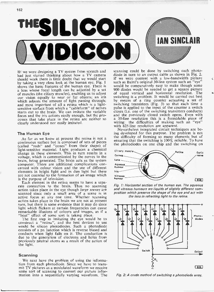
TELEU sign 124 FEBRUARY SERVICING.CONSTRUCTION.COLOUR.DEVELOPMENTS 19/4 CONVERTING FOREIGN also inside SIMPLE FET VOM THE SILICON VIDICON SERVICING THE DECCA MS 2000 SERIES
Transcript of FEBRUARY …americanradiohistory.com/Archive-Practical/Television/70s/...february...

TELEU sign 124FEBRUARY
SERVICING.CONSTRUCTION.COLOUR.DEVELOPMENTS 19/4
CONVERTINGFOREIGN
alsoinside
SIMPLE FET VOM
THE SILICON VIDICON
SERVICING THE DECCA MS 2000 SERIES
WITWORTH
TRANSFORMERS
MONOCHROMETV Line out -put transformers
(Discounts to Trade)
ALL ONE PRICE£5.17 EACH V.A.T. & CARRIAGE PAID
BUSHTUG versionsTV75 or CTV76 or CTV77TV78TV79TVI33TV84TV85TV86
TV 25TV 25UTV 28TV 34TV 35TV 35RTV 38TV 38RTV 39TV 41TV 45
TV9I TV 48TV92 TV 61TV93 TV 65TV94 TV 66TV95 or C TV 71TV96 or C TV 75TV97 TV 76TV98C TV 78TV99 or C 815TVIO0C 83TVIOIC 83DTVIO2C 83STV 103 or D 8355TV105 or D or R 855TV106 86TV107 86DTV108 86STV109 8655TV I I 2C 915TVI 13 91DTVII5 orCorR 93STVI 18 93DTVI23TV124From model TVI 23 to TV139 there havebeen two types of transformer fitted.One has pitch overwind, the other hasplastic moulded overwind.Please state which type required asthey are not interchangeable.
BAIRD600 628 662 674602 630 663 675604 632 664 676606 640 665 677608 642 666 681610 644 667 682612 646 668 683622 648 669 685624 652 671 687625 653 672 688626 661 673Please quote part No. normally foundon tx. base plate; 4121, 4123, 4140 or4142.
DECCADR20 DR34DR21 DM35DR23 DM36DR24 DM39CDR29 DR4IDR30 DM45DM30 DR49CDR3 I DM55DR32 DM56DR33 DR6I
DR7 IDR95DR100DR101DRI21DRI22DRI23DR202DR303DR404
DR505DR606666TV-SRG777TV-SRG
MSI700MS2000MS2001MS2400MS2401
SOBELLT24 ST284 or ds 0 lOdst 033SC24 ST285 or ds 012 038TPSI73 ST286 or ds 013 039TPSI80 ST287 or ds 014 047STI 95 or ds ST288 ds 018 048STI 96 or ds ST290ds 019 0575TI97ds ST29 Ids 020 0585C270 ST297ds 021 063T278 I 000ds 022 064ST282 I 002ds 023 065ST283 I 005ds 032 066
MURPHYV3I0 V430 V520 V879 or C V789 V2015S5V3IOA V430C V530 V923 V153 V20I6SV310AD V430D V530C V929 or L V159 V20175V310AL V430K V530D V973C VI73 V2310V310CA V440 V539 V979 V179 V231ICV320 V440D V540 V653 X V1910 V24I4DV330 or D V440K V540D V659 VI913 V24 I 5DV330F or L V470 V649D V683 VI914 V24155V410 V480 TM2 Chassis V739 V2014 V241505V4 IOC V490 V843 V735 V20145 V24I6DV4I OK V500 V849 V783 V201 5D V23165V420 V510 V873 V787 V20 15S V24175V420K V519Two types fitted. One has pitch overwind, the other has plastic mouldedoverwind. Please state which type required as they are not interchangeable.
PHILIPSIll la
23TG 1 I 3a23TG12Ia23TG I 22a23TG13Ia23TG 142a23TG I 52a237G153a23TG 156a23TG 164a23TG 170a23TG17Ia23TG I 73a23TGI75a23TG 176a23FG632
G 1 9T210GI9T211GI9T212G 1 9T213G 19T214G19T215G20T230G20T232G20T236G20T238G20T300G20T301G20T302G20T306G20T307G20T308
G23T210G23T2 I I
G23T2 I 2G24T230G24T232G24T236G24T238024T300G24T30 IG24T302G24T306G24T307G24T308
GEC2000 2015 2022 2043 20642001 2017 2023 2044 20652010 2018 2032 2047 20662012 2019 2033 2048 20822013 2020 2038 2063 20832014 2021 2039
PYEI I u SeriesI2u13u State Pt. No.14u required15u AL2 1003 or20u 772494
V700 or A or DV7I0 or A or D State Pt. No.V720 required-V830A or D or 772444 orLBA 771935
FERGUSON, ULTRA, MARCONI, H.M.V. (BRC. Jellypots).ALL MODELS IN STOCK.
ALBA, COSSOR, EKCO, FERRANTI, K.B., PYE. ALL MODELS IN STOCK.
E.H.T. RECTIFIER TRAYSTHORN B.R.C.MONOCHROME
ORDERRef.
980, 981, 98291 I, 950/1, 960950/2, 1400 -5 stick1400 Portable -3 stick1500 20" 3 stick1500 24" 5 stick1580 Portable -2 stick1590, 1591
RTIRT2RT3RT3ART4RT5RT16RTI7
MAKE
DECCADECCADECCAGECITT -KBPHILIPSPYEPYEBUSH MURPHYBUSH MURPHYTHORN BRCTHORN BRCTHORN BRCTHORN BRC
CHASSISCOLOUR
CTVI9, CTV25CS 1910, CS2213CS 1730Dual & Single std.CVC-1, 2, 3G8691, 692, 693, 697713Single std plug-inDual standard2000300080008500
CO LO U R TV Line out -put transformersTHORN (BRC)2000 ChassisScan 0/P Tx.
BUSHCTV25 Mk. I & 2C10.10 ea.
EKCOCT 102CT 104 011.70 ea.
03.30 EHT 0/P Tx. CTV25 Mk.3 CT 103C3.60 3000 Chassis CTV 162 CTIO5C3.90 Scan 0/P Tx. [7.90 ea. CT 106C3.60£3.60E3.90
EHT 0/P Tx.8000 Chassis
CTV 167 M k. I & 2C10.10 ea.
CT 107CT 108CT 109
£3.50 8500 Chassis CTVI67 Mk.3 CT IIIC1.30 All C6.80 ea. CTV I 74D CT 120
CTV 1825 CTI 21 &/TCTV 184S CT 122 08.90 ea.
GECCTV I 87CSCTV194S
PYEDual Standard CTV 197CSingle Standard CTV 199S CT70£7.90 ea. C7.10 ea. CT7I C11.70 ea.
£6.30[6.30C5.80C6.1006.3006.3006.10
CT72CT73CT78CT79CTI52CT153CT 154 08.90 ea.
ITT -KBCVC I ChassisCVC2£7.10 ea.CVCS Chassis
DECCACTVI9 Valve Rec.CTV25PrimaryCoil
£6.40 £8.10 ea. £3.70 ea.06.30C8.40C7.30E6.60E4.10E4.20
CTV19 D/S TriplerCTV25CTV25 S/S TriplerCS1730£7.80 ea.CSI910
MURPHYCV1912 CV2510 Mk.3CV1916S CV25I I Mk.3CV2210 CV25165CV2212 CV2610CV2213 CV26I ICV22 I 4 CV2614
PHILIPSG6 Chassis D/SG6 S/SC8.70 ea.
08 ChassisC7.90 ea.
CS2213C7.10 ea.
C7 on --CV2510 Mk.CV25I I Mk
Every item listed stocked. Most newer and older models in stock. S.A.E. for quotatiunFor by -return service contact your nearest depot. Callers welcome.
Tidman Mail Order Ltd., Dept. NA.236 Sandycombe Road,Richmond, Surrey.London : 01-948 3702
NO HIDDEN EXTRAS -
Hamond Components (Midland) Ltd., Dept. NA.89 Meriden Street,Birmingham 5.Birmingham : 021-643 2148
PRICES INCLUDE V.A.T. and CARRIAGE

145
11.)..- -
1111
-i 41
9 MADE IT MYSELF"Imagine the thrill you'll feel ! Imagine how impressed \people will be when they're hearing a programme on a ".modern radio you made yourself.
Now! Learn the secrets of radioand electronics by building your
own modern transistor radio!Practical lessons teach you sooner
than you would dream possible.What a wonderful way to learn - and help qualify yourselffor a new, better -paid career! No dreary ploughing throughpage after page of dull facts and figures. With this fascinatingTechnatron Course, you learn by building!
You build a modern TransistorRadio . . . a Burglar Alarm. Youlearn Radio and Electronics bydoing actual projects you enjoy -making things with your ownhands that you'll be proud to own!No wonder it's so fast and easy tolearn this way. Because learningbecomes a hobby! And what aprofitable hobby. Because oppor-tunities in the field of Radio andElectronics are growing tasterthan they can find people to fill thejobs!
No mathematics,no soldering - yet youlearn faster than youever dreamed possible.Yes! Faster than you can imagine,you pick up the technical knowhow you need. Specially preparedstep-by-step lessons show youhow to: read circuits - assemblecomponents - build things -experiment. You enjoy everyminute of it!
You get everything you need.Tools. Components. Even a ver-satile Multimeter that we teachyou how to use. All included inthe course AT NO EXTRACHARGE' And this is a courseanyone can afford. You can evenpay for it in easy payments - infact you could make extra cashfrom spare -time work when you'veturned yourself into a qualified manthrough B.I.E.T. training.
So fast, so easy,this personalised coursewill teach you even ifyou don't know a thingtoday!No matter how little you knownow,, no matter what your back-ground or education, we'll teachyou. Step by step, in simpleeasy -to -understand language, youpick up the secrets of radio andelectronics.
You become a man who makesthings, not just another of themillions who don't understand.And you could pave the way to agreat new career, to add to the thrilland pride you receive when youlook at what you have achieved.Within weeks you could hold inyour hand your own powerfulradii). And after the course youcan go on to acquire high-powered technical qualifications,because B.I.E.T.'s famous coursesgo right up to City & Guildslevels.
Send now for FREE76 page book - see how
easy it is - read whatothers say!Find out more now! This is thegateway to a thrilling new career,or a wonderful hobby you'llenjoy for years. Send the couponnow. There's no obligation.
To: BRITISH INSTITUTE OF I BTV34ENGINEERING TECHNOLOGYAldermaston Court, Reading R67 4PF OH
Yes. I'd like to know more about your course. Please sendme tree details-plus your big, 76 -page book that tellsabout all your courses.
BRITISH INSTITUTE OF ENGINEERING TECHNOLOGY
42Telephone.
arshal 5SEMICONDUCTOR SPECIALISTS
A. MARSHALL Et SON (LONDON) LTDCricklewood Broadway, London, N .W.2
01 -452 016112 Telex: 21492 Cable: Coninst London
colour televisionComplete kits for the following units:
Kit No. 1-PAL DECODER £8.42
Kit No. 4-I.F. STRIP £8.26
Kit No. 8-R.G.B. BOARD £6.66
Kit No. 10-TIME BASE £7.50FOR COLOUR TELEVISION PROJECT
FEATURED IN THIS MAGAZINE
Guitar amplifier100 WATT
complete with case and all components£23.50
Postage and packing 60p
`SCORPIO' ignition systemCAPACITOR DISCHARGE IGNITION SYSTEM
(as described in Practical Electronics Nov. 1971)COMPLETE KIT £10.00 P. & P. 50p
SPECIAL OFFERRECORDING TAPES-STANDARD PLAY
102"-2,400 ft. £1.25 to clearPostage and packing 30p
Kellner Construction KitsAV7 Aerial Amplifier For LW, MW, SW,VHF and T/V Channels 2-12 . Requires4-12V. Current 2MA. 2-25 db Amplification
Factor I/P IMP 5080 OHMS.83
Price£1.Postage and packing 20p£2.04
HE723. Six Numeral Digital Clock. 15 I/csand One Power Transitor ExtremelyAccurate All Components P/C Board
and Case. Price £29.95.Postage and packing 60p
ALL PRICES EXCLUSIVEOF V.A.T.
146
TV LINE OUTPUT TRANSFORMERSALL MAKES SUPPLIED PROMPTLY by our
RETURN OF POST MAIL ORDER SERVICEAll Lopts at the one price
£4.40 TRADE £4.95 RETAIL (INCLUDING V.A.T.)Except Post and Packing 30p COD 33pBUSH MODELS TV53 to TV67, TV94 to TV101. HMV MODELS 1876 to 1878, 1890 to 1896, FR 20.EKCO MODELS TC208 to TC335, TV407 to TV417. MURPHY MODELS V280 to V330, V420, V440, 653X to 789 OIL -FILLED.FERGUSON MODELS 305 to 438, 506 to 546. REGENTONE MODELS 10-4 to 10-21, 1718, R2, R3, 191, 192.FERRANTI MODELS 1084 to 1092. RGO 519-621, 710, 711.
ALL AT £2.75 + 30p PbP
EHT TRAYS SUPPLIED -MONO & COL.All Lopts NEW and GUARANTEED for SIX MONTHS
E. J. PAPWORTH AND SON Ltd., 01-540 395580 MERTON HIGH ST., LONDON, S.W.19 01-540 3513
B. BAMBER ELECTRONICS 20 WELLINGTON STREET, LITTLEPORT,CAMBS. Telephone: Ely 860185 or 860363
MULTICORE SOLDER, Ilb reel, 60/40 alloy,20SVVG C1.25
PYE LYNX (TV camera) MANUALS L1.5020-25kHz XTALS for TV sync gen. B7G glass,
new £2.20IMSLIDE, telescopic rack runners, 23in long,2 sections L1.10 per pairMAGNETIC TAPE, lin on I4in reels (ex -
equipment) LI.50, carriage 50pSLEEVING, silicon rubber, 1mm bore, 25yds, 25pFLEXIFORM GROMMET, for odd -shape holes,
30ft for 25p
SPECIAL 50p PACKSGROMMETS, mixed bag 50pELECTROLYTICS, mixed, 20 for 50pJACK PLUGS, 4 for 50pBNC PLUGS, 4 for 50pBNC SKTS, round -hole mount, 5 for 50pHELLERMAN SLEEVES, mixed bag 50p
ELECTROLYTICS200+200 + 60mfd at 300V, 44p200+ 100mfd at 275V, 40p100mfd at 350V, 3 for 50p20+20mfd at 350V, 3 for 50p4000mfd at 40V, 44p2000mfd at I 5V, 2019--500mfd at 100V, 3 for 50p
DIECAST BOXES (NEW)3f X 41.k. 65p3* x4 31, L1.1010Ix 61 X 2f, LI.85
x 41 x 2Z, 80p61x 4f x 24, LI.20131 X 51 X 4*, L2.25
PYE COLOUR PICTURE MONITORTYPE 7100/00-05 PANELS & SPARESPlease note that panels are not completewith all the components. Circuits suppliedwith all boards.Video Amp. P.C. Board L1.00C.R.T. Base with R.G.B. Amp L2.20Vertical Scan P.C. Board LI.50Horizontal Scan Osc P.C. Board £2.00Sync Separator P.C. Board £1.10Convergence Inductor P.C. Board £2.20Scan Coils L5.50Convergence Coils £2.75Purity and Blue Lateral Coils £0.55Power Unit Heat Sink with 2 x 40251 and
I x 40318 LTransistors Type NKT 0032 £0.3022 WAY UECL sockets only L0.2225 WAY ISEP plug and socket £0.40 set33 WAY ISEP plugs only L0.22
COLOUR MONITOR DECODER UNITSby leading British maker, designed to BBCstandards. Units consist of Chrominance module,PAL filter and delay module, Luminance module,and Encoded input video module. All units brandnew, tested, and complete with service manualand edge connectors L30.00 set.PHILIPS MONITOR DECODER PANELS,type EL6818/50F, PAL C20.00, NTSC L15.00, nodetailsMULLARD Monochrome scan coils LI.10EHT Valveholders, B9A new 10pCRT Bases, BSA. new 5pMAINS ISOLATING TRANSFORMERS,375VA, tapped primary, 240V output, new L5.50
VALVES (New Mullard)6080 55p EC8I 30pECC8I 30p EF184 30pECC83 25p PCF80 30pEZ8I 25p OB2 25p30FLI2 (New Mazda) 40p12E1 (ex -equipment, tested) 50p
TRANSISTORS (New)BUI05/01 £1.00 ACI 28 6 for 500C200 3 for 50p BY 126 6 for 50pBSX2I 3 for 50p2 X 2N3442 on heat sink, 120V, 10A, 117W, ex-equipment L1.00BYX25/600 Stud rect., 600V, 20A, on heat sink,ex -equipment 20p
WE HAVE LARGE STOCKS OF PROFES-SIONAL TEST GEAR AND A VARIEDSTOCK OF PYE RADIOTELEPHONEEQUIPMENT
Please enclose S.A.E. for all enquiries
TERMS OF BUSINESS cash with order.Callers welcome by appointment.PLEASE NOTE THAT ALL PRICES INCLUDE VAT.
POSTAGE AND PACKING CHARGE. 20pON ALL ORDERS, except where stated.
147
SENDZCOMPONENTS
COLOUR 25 KV TRIPLERS
£1.70 4 17p V.A.T.
REPLACEMENT TRIPLERSPYE C72 SERIESGEC 2028 SERIESPHILIPS G8 SERIES
£3.00 + 30p V.A.T.
E.H.T. RECTIFIER STICKSX80/150D
10p 1p V.A.T.
TRANSISTOR TUNER UNITSVHF/UHF6 Push Button VHF/UHF6 Push Button UHF
UHF300 Mixed Condenser350 Mixed Resistor100 w/w Resistor40 Mixed Pots
£2.00 20p V.A.T.£2.50 25p V.A.T.£3.00 30p V.A.T.£1.50 15p V.A.T.£1.00 10p V.A.T.£1.00 10p V.A.T.£1.00 10p V.A.T.£1.00 10p V.A.T.
PRINT PANELS WITH TRANSISTOREt RESISTOR Er CONDENSER Er RELAYS
£1.00 10p V.A.T.
Money returned if not completely satisfied
COLOUR PANELSTRANSISTORS RESISTOR CONDENSER ETC.
£1.00 10p V.A.T.
I.F. PANELS, with Transistors Et Resistor etc.,
10p 1p V.A.T.
SENDZ COMPONENTS2 WOODGRANGE CLOSE
THORPE BAY, ESSEX
P.P. PAID UK ONLY
Reg: Office Only-No Personal Callers Please
electronics reallymastered
...practical ... visual ... exciting !no previous knowledge no unnecessary theory no "maths"
BUILD, SEE AND LEARNstep by step, we take you through all the fundamentals ofelectronics and show how easily the subject can be mastered.Write for the free brochure now which explains our system.
1/ BUILD ANOSCILLOSCOPE
You learn how to buildan oscilloscope whichremains your property.With it, you will becomefamiliar with all thecomponents used inelectronics.
2/ READ, DRAWAND UNDERSTANDCIRCUIT DIAGRAMS
as used currently in thevarious fields of electronics.
FREEPOST NOW
tot'MOM
3/ CARRY OUTOVER40 EXPERIMENTSON BASIC ELECTRONICCIRCUITS 8, SEE HOWTHEY WORK, including :
valve experiments. transistor experimentsamplifiers. oscillators. signal tracer, pho-to electric circuit. computer circuit. basicradio receiver, electronic switch. simpletransmitter. a c experiments. d c expert.ments. simple counter, time delay circuit.servicing procedures
This new style course will enable anyone toreally understand electronics by a modern,practical and visual method-no math.. anda minimum of theory-no previous knowledgerequired It will also enable anyone to under-stand how to test, service and fneintain alltypes of electronc equipment. radio and TVreceivers. etc
or write tr you prefer not to cut page
BRITISH NATIONAL RADIO ft ELECTRONICS SCHOOL P.O. BOX 156, JERSEY
CHANNEL ISLANDS we el0 not emblee .......
Please send your free brochure, without obligation, to:
NAME
ADDRESS
BLOCK CAPS
PLEASE T L 24
special' free giftalso to all our students

148
Still waiting for spares Tom?You should have phoned
WHEREVER YOU ARE FOR BYRETURN DESPATCH. WILLOWVALE IS AS NEAR AS YOURPHONE
WILLOW VALEThe Wholesaler who knows what SERVICE is really about !
BY RETURN DESPATCH:- HOT LINES: 01-567 5400/2971
L.O.P.T's, TRANSISTORS, RECTIFIER TRAYS, COMPONENTSMONOCHROME and COLOUR C.R.T's, new and re- built.HUGE RANGE OF VALVES up to 46% DISCOUNT
A FULL RANGE OF TEST - METERS, SERVICE AIDS, TOOLS, ELECTROLUBEand Servisol products. Multicore soldert,,, plugs and sockets, capacitors, bias dndsmoothing electrolytics, volume controls, pre-sets, i, 1 and 2 watt carbon film re's
,----_We SPECIALISE in supplying the Service Engineer
Test eqUiprrent by : Labgear, Philips,.Meteronic etc. Colour bar & Pattern 68 PAGE CATALOGUEgenerators, osci I loscopes Ey meters V FREE ON REQUEST
Hot line willow vale ki,II
I would like 3 free copy of your catalogue
orders:- NateThe Service Department Wholesalers
LONDON: 4/5 The Broadway Hanwen London W7 01-567 5400] AddressGLASGOW: 74 Maxwellton Road Paisley 041-887 4949SOMERSET: 42 West End Street Somerset 045.84 2597
STRICTLY WHOLESALE ONLY NO RETAIL ENQUIRIES PLEASE.
149
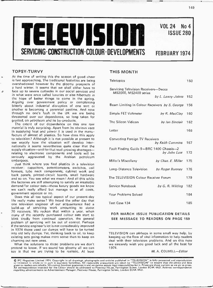
TELEVISIONVOL 24 No 4
ISSUE 280
SERVICING.CONSTRUCTION.COLOUR.DEVELOPMENTS FEBRUARY 1974
TOPSY-TURVYAt the time of writing this the season of good cheeris fast approaching. The traditional festivities are beingovershadowed however by the gloomy prospects ofa hard winter. It seems that we shall either have toface up to severe cutbacks in our social services andin what were once called luxuries or else hibernate inthe hope of better things to come in the spring.Arguing over government policy or complainingbitterly about industrial disruption of one sort oranother is becoming a perennial pastime. And nowthrough no one's fault in the UK we are beingthreatened over our dependence, so long taken forgranted, on petroleum and its by-products.
The extent of our dependence on this one rawmaterial is truly surprising. Apart from its obvious usesin supplying heat and power it is used in the manu-facture of almost all plastics. So how does this applyto television? Although it is not possible at present tosee exactlynationally it seems nevertheless quite clear that thesupply situation-and for that read growing shortages-relating to electronic components and tools will beseriously aggravated by the Arabian petroleumembargoes.
Just think where you find plastics in a televisionreceiver: capacitors, potentiometers, switches, coilformers, tube neck components, cabinet work andback panels, printed -circuit boards, small hardwareand so on. You see what we mean ! And all this whilethe factories are still attempting to satisfy an insatiabledemand for colour sets-those luxury goods we knowwe can't really afford but manage to at all costs,government squeeze or no.
Does this all too typical aspect of our present-daylife really make sense? We heard the other day thatone television engineer of our acquaintance had abuild-up of servicing work amounting to about70 receivers. We reckon that within a year, whenmany of the recently purchased colour sets start toblink tiredly from continual operation, the generalproblem of servicing will be out of control. Perhapsif the service engineer's lot is not considerably improvedin 1974 those used car dumps will have to be turnedinto old telly dumps. Yet, thinking back to oil, to keepexisting sets going makes more sense than to keep onchurning out new ones.
What the solutions to these problems are we don'tpretend to know. If we sound too gloomy all we cansay is that we are trying to be realistic. At least
THIS MONTH
Teletopics 150
Servicing Television Receivers-DeccaMS2000, MS2400 series
by L. Lawry -Johns 152
Beam Limiting in Colour Receivers by S. George 156
Simple FET Voltmeter by R. MacClay 160
The Silicon Vidicon by Ian Sinclair 162
Letter 166
Converting Foreign TV Receiversby Keith Cummins 167
Fault Finding Guide 9-BRC 1400 Chassis -2by John Law 172
Miller's Miscellany by Chas. E. Miller 175
Long -Distance Television by Roger Bunney 176
The TELEVISION Colour Receiver Forum 179
Service Notebook
Your Problems Solved
Test Case 134
by G. R. Wilding 182
184
185
FOR MARCH ISSUE PUBLICATION DETAILSSEE MESSAGE TO READERS ON PAGE 159
TELEVISION can perhaps in some small way help, bykeeping up the flow of vital information to help readersdeal with their television problems. And on this notewe sincerely wish you good luck and all the best for1974.
M. A. COLWELL-Editor
IPC Magazines Limited 1974. Copyright in all drawings, photographs and articles published in "TELEVISION" is fully protected and reproductionor imitation in whole or in part is expressly forbidden. All reasonable precautions are taken by "TELEVISION" to ensure that the advice and datagiven to readers are reliable. We cannot however guarantee it and we cannot accept legal responsibility for it. Prices are those current as we go to press.All correspondence intended for the Editor should be addressed to Fleetway House, Farringdon Street, London EC4A 4AD. Address correspondenceregarding advertisements to Advertisement Manager, Fleetway House, Farringdon Street, London EC4A 4AD.

150
UK SATELLITE TV PROSPECTS
At the Royal Television Society's convention atCambridge late last year R. J. Clayton, TechnicalDirector of GEC, spoke of the prospects for settingup a satellite TV service for the UK. He believedthat by the end of the present decade the technologyrequired will be available so that the decision onwhether to start space broadcasting "will be one ofneed, desire or choice". Preliminary CCIR studieshave suggested that four channels in Band VI(11.7-12.5GHz) will be made available to the UK,each carrying a wideband f.m. vision transmission.The use of f.m. for s.h.f. TV transmissions has con-siderable advantages such as reduction of the trans-mitter output power, less stringent converter noisefactor and oscillator stability requirements and betterco -channel performance.
A parabolic reflector receiving aerial of between80cm and lm diameter would be required and thiswould have to be installed with a pointing accuracyof about 0.5°-rather more accurate than presentday installation standards !
The Television Advisory Committee's 1972 reportsuggested that only national, not regional, coveragecould be provided by a UK satellite TV service. Mr.Clayton commented that subsequent work indicatesthat deployable satellite aerials could be producedwhich would track ground beacons with sufficientaccuracy to make regional programming in the UKpossible.
A number of firms are engaged in developmentwork to ensure that suitable converters will be avail-able. To reduce signal loss it is likely that conversionfrom s.h.f. to u.h.f.-also from f.m. to a.m. vision-will be undertaken at the masthead. To improveimage -frequency rejection and suppress local oscil-lator radiation a double superhet circuit is likelyto be employed. Temperature compensation anda.f.c. are likely to be necessary to obtain the stabilityrequired. Mr. Clayton felt that low-cost, mass-pro-duced converters will be produced without difficultyand that the costs previously suggested-between£50 and £80 for a dish aerial plus converter-are"on the high side for 1980 at today's money values".
In conclusion Mr. Clayton pointed out that muchof the technology for space broadcasting is alreadyavailable and that likely costs can be predicted moreaccurately in this field than in many other areasof technology. He felt that the main problem couldbe that the demand will not be there by the timethe technology is available; this would be particularlyunfortunate for the UK industry which has builtup a significant ability to develop and manufacturesatellites. Mr. Clayton reported that there is the capa-
bility within at least one UK company to design andmanufacture broadcasting satellites and the asso-ciated ground equipment, and that such companiescould well be prepared within the next year or soto discuss "firm prices and guarantees of satisfactoryoperation for definite periods". Absence of a homemarket could make it difficult for UK firms to par-ticipate in the development of satellite TV systemsin overseas markets.
HOME VIDEO SYSTEMS
Another speaker at the convention was Sir JohnStewart -Clark, managing director of Philips ElectricalLtd., who spoke on video systems for domestic use.What he had to say was of particular significancesince Philips are active in both the videotape andvideo disc fields. The well known Philips VCRmachine offers flexibility in being able to record aprogramme being watched, or one programme whilethe viewer is watching another, or under the controlof a time switch in the viewer's absence, in additionto providing playback. It is understood that presentdemand is already in excess of the capacity of Philipsplants (on the Continent) to produce these machines.The view held by Philips is that one in ten colourset owners is eventually likely to want a VCRmachine, giving a projected potential market ofsome 1.5 million machines by the time the numberof colour receivers has risen to 15 million (the esti-mated saturation point for the UK).
It appears however that Philips feel that the realmass market will lie in a cheaper domestic videosystem providing playback only, which is wherethe video disc comes in. The Philips video long-playing record (VLP) system is still in the develop-ment stage. It employs a laser beam to scan thecoded information which consists of a series of dotsand dashes recorded on the disc as a spiral. Thedots and dashes are of uniform width and depthbut vary in their lengths and spacings to give theinformation required to regenerate a complete colourtelevision signal. Since the laser beam is the onlymechanical contact with the disc there is no surfacewear, and as the material used is the same as thatused for audio records the eventual production costcould be only a few pence per disc.
Sir John concluded that "with such machines weare on the edge of a revolution that will lead to asubstantial change in home entertainment equipment.There are still problems to be solved, but I predictthat in a few years' time we shall be able to producea video long player with records giving up to anhour's programme that can be fed into any colourset, and with the records costing not significantly
151
more than a long-playing gramophone record today".Longer reports of the RTS convention are given
in the November/December 1973 and subsequentissues of the Royal Television Society Journal.
UHF AERIAL GROUPINGS AMENDED
The Radio and Electronic Component ManufacturersFederation has revised the standard u.h.f. aerialgrouping/colour coding system. The amendmentsare only slight but should be noted. There are nowthree categories as follows: group A, channels 21-34,colour code red; group B, channels 39-53, colourcode yellow; group C/D, channels 48-68, colourcode green.
TRANSMITTER OPENINGS
The following relay stations are now in operation:Buxton (Derbyshire) BBC -1 channel 21, IBA (ATVprogrammes) channel 24, BBC -2 channel 27. Thestation will relay BBC -1 Midlands regional pro-grammes: later it is hoped that programmes fromManchester will be relayed. Receiving aerial groupA.Ladder Hill (Whaley Bridge near the Cheshire/Derbyshire border) IBA (Granada programmes)channel 23. Receiving aerial group A.Plympton (Plymouth, Devon) IBA (Westward pro-grammes) channel 61. Receiving aerial group C.Abertillery (Monmouthshire) IBA (HTV Wales pro-grammes) channel 25. Receiving aerial group A.
All these relay transmissions are vertically polar-ised.
FIRST UK PRODUCED 4in. VIDICON
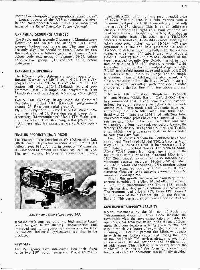
The Electron Tube Division of EMI Electronics Ltd.(Blyth Road, Hayes) has introduced an 18mm (fin.)vidicon, type 9831, for use in compact TV cameras.It is intended at present as a direct replacement type.The new vidicon features a low -wattage heater,
EMI's new 18mm vidicon type 9831.
separate mesh construction and a high quality targetlayer to give better shading characteristics andimproved sensitivity. Specialised versions of the tubefor various industrial applications are also to beproduced.
NEW SETS
The Pye group have introduced into their Ekcorange two 110° colour receivers. Model CT262 is
fitted with a 22in. c.r.t. and has a recommended priceof £292; Model CT266 is a 26in. version with arecommended price of £320. These sets are fitted withthe group's 731 chassis. This is an all solid-statechassis incorporating eight i.c.s. Four of these areused in a four-i.c. decoder of the type described inour November issue. The others are a TBA750Qintercarrier sound i.c., TCA270Q demodulator/a.g.c./a.f.c./video preamplifier i.c., an SN76544N07 syncseparator plus line and field generator i.c. and aTAA550 to stabilise the tuning voltage for the varicaptuner. A wide neck 110° tube is used, with MullardPhase II convergence and timebase circuitry of thetype described recently (see October issue) in con-nection with the RRI 110° chassis. A single BU108transistor is used in the line output stage, a singleBD183 in the field output stage and a pair of BD131transistors in the audio output stage. The h.t. supplyis obtained from a stabilised thyristor circuit, withslow -start system to limit the initial switch -on currentand a thyristor overvoltage protection circuit whichshort-circuits the h.t. line if it rises above a presetvalue.
A new UK setmaker, Steepletone Products(Cinema House, Middle Barton, Oxford OX5.4DA),has announced that it can now take "substantialorders" for colour receivers for delivery to the tradeduring 1974. Three models, all UK made, have beenannounced, the S074 fitted with 20in. tube, M274fitted with 22in. tube and L674 fitted with 26in. tube.No recommended prices have been suggested but thesets are said to be in the "de luxe" class and eachwill undergo a four-hour soak test before leaving thefactory. The chassis uses hybrid circuitry, and Toshibac.r.t.s which have a guarantee that can be extendedto four years are fitted.
Two new colour sets from the Continent have beenannounced. The Indesit Model T26LGB comes fromItaly and is priced at £390. It incorporates a 110°26in. tube and a hybrid chassis. The Siemens ModelAlpha FC387 comes from Germany and is in theluxury class with a price tag of around £500. It is a110° 26in. model. Siemens are also introducing avideotape cassette recorder, Model FM101, whichrecords in colour and includes a 26in. monitor colourset. The suggested price is about £700. It takesstandard Videocord type cassettes giving 30, 45 or 60minutes recording time.
Finally this month two new mains -battery mono-chrome portables. The Ultra Model 6830, fitted witha 12in. tube, incorporates the Thorn 1621 chassiswhich was described in this column last November.The recommended price is £67. From ITT comes a15in. version of their Featherlight 12-the Feather -light 15. This carries a recommended price of £73.50.
GOVERNMENT SUPPORTS CABLE TV
Recent statements by the Minister of Posts andTelecommunications Sir John Eden indicate thefavourable view the government takes of cable TVoperations. Sir John has stated in the House of Com-mons that consideration is being given to "the bestway in which the future of cable television could beencouraged". For the present the Ministry appearsto wish to see further experiments along the linesof the local cable TV services already in onerationat Greenwich, Bristol, Swindon and Sheffield, butof wider scope. This is felt to be necessary before the"delicate" questions of the form of control andfinance of cable TV operations can be finally decided.
152
44, SERVICINGR' televisionN receivers
L LAWRY JOHNS1 DECCA MODELS MS2000 Et MS2400
THESE are hybrid receivers using a combination ofvalves, transistors and an i.c. for the intercarriersound channel. As they are single -standard sets theabsence of a v.h.f. tuner means that the amplificationthis would have provided must be made up either inthe i.f. strip or in the u.h.f. tuner. The latter arrange-ment is adopted, a three transistor tuner unit beingused. The aerial signal is amplified by the normalr.f. transistor (AF239) and is then passed to themixer stage (AF139) where the required i.f. is ex-tracted and passed to an AF106 transistor for ampli-fication before being conducted via a screened leadto the filters on the main chassis. The main i.f.amplification is then carried out by the controlledEF183 stage and the straight EF184 amplifier.
Demodulated SignalsThe composite waveform is detected by D202,
filtered and capacitively coupled to the video ampli-fier section of the PFL200, with d.c. restoration bymeans of D205. D204 is an anti -lockout diode tolimit the video drive under high contrast conditions.The picture signals and sync pulses are developedacross R230 and passed through correction com-ponents to the c.r:t. cathode and the sync separatorcontrol grid.
Sound CircuitsThe 6MHz intercarrier sound signal is picked off
at the video amplifier cathode and fed to the ceramiccrystal CF201. This passes the 6MHz f.m. signalonly to the MC1351P integrated circuit which carriesout amplification, limiting, detection and a.f. pream-plification. The a.f. signal appearing at pin 2 of thisi.c. is coupled via C225 to the volume control andis then returned via C232, D203 and C236 to pin 9of the i.c. D203 is included in this feed to mute thea.f. circuits until the valves warm up and the pictureappears. Once the EF184 conducts sufficiently thevoltage across its cathode resistor R215 biases D203on and the a.f. channel is no longer cut off. Theamplified a.f. signal at pin 10 of the i.c. then passesto the output transistor TR201 (which is clampedthrough its insulator to chassis-more about thatlater). The collector -base junction of this transistoris protected by D201.
TimebasesThe anode load resistor of the sync separator
section of the PFL200 is R112. C107 couples theline sync pulses to the flywheel discriminator (V115)
circuit while C110 feeds the field sync pulse shapingnetwork.
The line timebase follows the usual Decca pattern.The flywheel line sync and oscillator circuits arebasically as used in the DR100 series which wecovered in the March and April 1971 issues. Theline output stage also follows established practicednd offers no headaches.
Field Timebase ValveThe field timebase uses a 30PL14 valve in an
otherwise commonly encountered oscillator -outputcircuit. Let us be clear however that the pin connec-tions of the 30PL14 are not the same as those ofthe PCL85. The 30PL14 in fact is an up -rated versionof the earlier 30PL13 which was not too far removedfrom the PCL82 (although far enough to preclude
replacement in most timebases).
H T Et Heater SuppliesThe power supplies are conventional from both
the heater and h.t. point of view. A thermistor isincluded in series with the heater circuit droppingdiode (D104) and there is a separate 1 A fuse inseries with the h.t. diode (D101). The smoothingchoke (CHI) is followed by a fairly elaborate smooth-ing system of resistors and electrolytics which supplythe various parts of the receiver including the soundoutput transistor. It should be appreciated that thistransistor works at a fairly high collector voltage(about 120V) but we will have more to say aboutthis stage later.
LT SuppliesThe supply to the tuner is derived from the h.t.
line through the 15kn resistor R302 and is clampedto 12V by the zener diode D301 (ZG12). A similararrangement is used to supply the MC1351P i.c. Inthis case the supply is taken from the same h.t. linethat feeds the audio output transistor, via R217(5kn) with clamping to 12V by D206 and additionalsmoothing provided by R242 and C227.
No H TComplete absence of h.t. is most often due not to
the h.t. fuse F2 failing but to one of the 1712 sections(R104/5/6) of the mains dropper going open -circuit.The value of the replacement used is not too criticalwithin 14 to 20n but the temptation to short outthe faulty section must be resisted as all sorts of

153
LEARN about MODERN TV Designby building this Heathkit 12" B/W Portable
The new Heathkit GR-9900 portable 12" UHFMonochrome Television kit. A unique chance to doublethe pleasure available from any other television set -because you build this yourself.
We've used the latest modular construction andadvanced design concepts to produce an outstandinglyhigh performance TV worthy of the Heathkit name.All the main electronics are mounted on two easy -to -assemble printed circuit boards-this plus the use of noless than four integrated circuits perform the complexfunction of IF, video, sound, line frame and scan.Factory pre -aligned coils make alignment very easy andthere are four presetable pushbutton controls forchannel tuning-a luxury found in very few other models.The quality and fidelity is therefore excellent, and of afar higher standard than most ready -built televisionsin the shops.
The GR-9900 is portable too-equally at home on
FREEHeathkitCatalogueContains something foreveryone : Hi -Ft Stereo.Testers & Instruments, SWL,Metal Detectors even aBattery charger Kit.Mail the coupon ... Today!Heath (Gloucester) Limited,Gloucester GL2 6EE.
LONDON showroom233 Tottenham Court RoadTel 636 7349
the mains or off your 12 volt battery for car, boat orcaravan use. Add to this Heath's world renownedexperience in the design of equipment for first-time kitbuilders, and you will be impressed on all counts ofengineering, styling, and performance.
The instruction manual is surprisingly simple with big,clear illustrations to map out your way. Would-beTV engineer? Here's your chance to learn-by actuallybuilding a television yourself. The manual not onlyshows you how to get 100% personalised quality controlon your own; in the event of anything going wrong, aTrcuble-Shooting section enables you to find the fault-and, in most cases, to put it right unaided.
The GR-9900 is a kit you'll be proud to build andown. You have a choice of fully finished cabinets inteak or modern white and the kit price, E62.70 (carriageextra), includes a FREE high performance indoor aerial.
Choose cash or Heath Monthly Budget Plan(Mail order prices and spricilications subtect to change without notice
r -Please send me a FREE Heathkit catalogue
Name
Address
HEATH
1..,LHeath (Gloucester) Limited,Dept T.2.74Gloucester GL2 6EE. Telephone 0452 29451 1

154
L20810
L203
LINKR229
30
R231.)
R215
I R214
L204TO
L206
LINK
(4411
0CC
c4cc
C245
QO
R R203
L202To
L203
C
L201
L207
C217
C 247
C236
fl
R242
C227C205C247
219
DCF20
IN=C220
LINK
*232I R223 I
Fig. 1: Layout of the i.f. panel
Fig. 2: Control panel layout
funny things can happen if the supply voltage israised-though they may not appear to be likelyat the time. Failure of the line output transformeris one of the not so funny things that can resultfrom this action, together with early deteriorationof the main electrolytics.
Effect of faulty R107Still on the subject of resistors R107 is one of the
h.t. supply components that can cause a lot oftrouble if it becomes open -circuit. Whilst the lineoutput stage is fed direct from the junction R124/R107 (R124, 1S2, provides field scan correction-notethat it is in series with the field deflection coils) theline oscillator is fed from the junction R107/C105.Should R107 become open -circuit or be overloadedby a partial short the ECC82 line oscillator (V116)
cannot work and line drive to the PL504 line outputvalve is thus absent. This results in the PL504 andthe PY800 boost diode overheating. The PY800 maynot survive this sort of treatment: in fact it maywell register its objection by developing a cathode -to -heater short, resulting in the heater going open -circuit before the fuses have time to respond. Thefault may at first sight therefore appear to be oneof an open -circuit heater chain. When the PY800has been replaced and has had time to warm uphowever the overheating will be obvious and shouldimmediately direct attention to the ECC82 and itsh.t. supply. This sequence of events does notalways occur and the PL504 and PY800 may simplysit there glowing away waiting to be relieved oftheir burden.
CONTINUED NEXT MONTH

13 2
07
Inpu
trr
ue,
tune
r
/ 33-
5MH
z tr
apS
MM
e tr
ap1
r13
201
R?2
C20
66
22
300P
.R
20 437
Coo
l
C20
2S
D LI
C20
4r
j 0201SD
12k
1
I 2
L-
0025
1,1
AF
2396
RF
ampl
ifier
1st
IF a
mpl
ifier T
c>z(
r1C
S
C9 tpl
6-I
ind
IF a
mpl
ifier
R2
C20
5203
330
II6Z
0047
rL
1211
R21
602
23
R21
522
322
6
005
15-0
047
5.6
-r
016
C13 005
-11 1r 2
A F
139
142
r6:0
51r6
- -
- -
I -00
25
Mix
er
CIS 15
0
RIO
RI;
65<
407
Vid
eoam
plifi
er
C23
730
3S
I12
11
Z26
0231
207
309
NS
048
lest
po.
nt rC
22I
Tr3
AF
106
20.
m
62p0
.r 6
6
F__
_1
lop
C21
300
To
IFI
Mop
cn,
R30
2/03
01
\-s.
jr-r'
IFpr
eam
plifi
er
-4
6230
02g0
9O
k
Tub
eca
thse
PF
L 20
0'0
0'
1324
061
306
90V
12,
C24
4
0237
.009
0706
0236 15
0
OZ 2
1207
6M
C13
5117
Inte
rcar
rle,
soun
d
Syn
cse
para
tor
C21
010
2
C24
714,
162
6242
c227
b C
24(1
206
1652
4213
2512 13
219
R22
4
200-
250v
,de
C30
1P
ower
T"
cP"'
Edg
e co
nnec
tor
F b
oa r
d
To
Nric
,on
1320
6/C
214
1640
04
303
VO
R30
19/
DC
00,
PO
LO
M1E
340
120V
1.35
V
0231
0015
6302
v53
12V
totu
ner
0301
7012
1232
op
°,02,
014.
IR22
7
mat
C23
6rn
Atm
Fig
. 3: C
ircui
t dia
gram
of t
he tu
ner
unit
and
sign
al s
tage
s, D
ecca
Mod
els
MS
2000
and
MS
2400
.
Aud
io04
.11p
ut
00
156
S. GEORGE
BEAR LIMITINGIN
COLOUR RECEIVERSAPART from a few early models all colour receiversincorporate beam limiting circuitry. The reason forthis is as follows. Since e.h.t. circuits have a con-siderable internal resistance, even small increasesabove the designed -for e.h.t. current result in areduction of the e.h.t. voltage, degrading the con-vergence and focusing, while really excessive currentdemand imposes a heavy strain on the entire e.h.t.and line output circuitry, a condition which it isespecially necessary to avoid in solid-state receivers.
Colour -Difference Tube DriveReceivers employing colour -difference c.r.t. drive
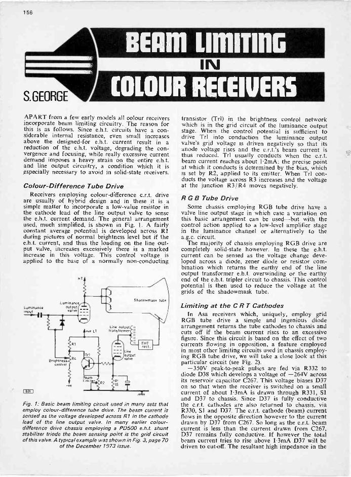
are usually of hybrid design and in these it is asimple matter to incorporate a low -value resistor inthe cathode lead of the line output valve to sensethe e.h.t. current demand. The general arrangementused, much simplified, is shown in Fig. 1. A fairlyconstant average potential is developed across RIduring pictures of normal brightness level but if thee.h.t. current, and thus the loading on the line out-put valve, increases excessively there is a markedincrease in this voltage. This control voltage isapplied to the base of a normally non -conducting.
Luminanceout putvalve
Brightnesscontrol
IhOtI
Fig. 1: Basic beam limiting circuit used in many sets thatemploy colour -difference tube drive. The beam current issensed as the voltage developed across R1 in the cathodelead of the line output valve. In many earlier colour -difference drive chassis employing a PD500 e.h.t. shuntstabiliser triode the beam sensing point is the grid circuitof this valve. A typical example was shown in Fig. 3, page 70
of the December 1973 issue.
transistor (Trl) in the brightness control networkwhich is in the grid circuit of the luminance outputstage. When the control potential is sufficient todrive Trl into conduction the luminance outputvalve's grid voltage is driven negatively so that itsanode voltage rises and the c.r.t.'s beam current isthus reduced. Trl usually conducts when the c.r.t.beam current reaches about 1.2mA: the precise pointat which it conducts is determined by the bias, whichis set by R2, applied to its emitter. When Trl con-ducts the voltage across R3 increases and the voltageat the junction R3/R4 moves negatively.
R G B Tube DriveSome chassis employing RGB tube drive have a
valve line output stage in which case a variation onthis basic arrangement can be used-but with thecontrol action applied to a low-level amplifier stagein the luminance channel or alternatively to thea.g.c. circuit.
The majority of chassis employing RGB drive arecompletely solid-state however. In these the e.h.t.current can be sensed as the voltage change deve-loped across a diode, zener diode or resistor com-bination which returns the earthy end of the lineoutput transformer e.h.t. overwinding or the earthyend of the e.h.t. tripler circuit to chassis. This controlpotential is then used to reduce the voltage at thegrids of the shadowmask tube.
Limiting at the C R T CathodesIn Asa receivers which, uniquely, employ grid
RGB tube drive a simple and ingenious diodearrangement returns the tube cathodes to chassis andcuts off if the beam current rises to an excessivefigure. Since this circuit is based on the effect of twocurrents flowing in opposition, a feature employedin most other limiting circuits used in chassis employ-ing RGB tube drive, we will take a close look at thisparticular circuit (see Fig. 2).
-350V peak -to -peak pulses are fed via R332 todiode D38 which develops a voltage of -264V acrossits reservoir capacitor C267. This voltage biases D37on so that when the receiver is switched on a smallcurrent of about 1.3mA is drawn through R331, Siand D37 to chassis. Since D37 is fully conductivethe c.r.t. cathodes are also returned to chassis, viaR330, SI and D37. The c.r.t. cathode (beam) currentflows in the opposite direction however to the currentdrawn by D37 from C267. So long as the c.r.t. beamcurrent is less than the current drawn from C267,D37 remains fully conductive. If however the totalbeam current tries to rise above 1.3mA D37 will bedriven to cut-off. The resultant high impedance in the

157
CRTbeamcurrent
-S1
R330680
R331-0.14V 220k
CRT
-26W
001
038BA148
R332390 flyback pulse
Current drainC267 from C2670.15
I 802 1
Fig. 2: Beam limiting and spot suppression circuit used inthe Asa CT5003/4 series. Beam limiting occurs at the c.r.t.cathodes: the chassis is very unusual in employing RGB
drive to the c.r.t. grids.
c.r.t. cathode circuit reduces the c.r.t. beam currentand the brightness level. The basic feature made useof here therefore is that when a semiconductor pnjunction is forward biased current can flow acrossthe junction in both directions.
The circuit also provides switch -off spot suppres-sion. When SI which is ganged to the mains switchis changed to the off position R331 is short-circuitedand the high negative voltage across C267 is appliedto the tube cathodes. As a result the three beams arebriefly turned full on, discharging the e.h.t. capaci-tance before the timebases cease to scan out theraster.
Limiting at the C R T GridsAnother simple limiter which acts directly on the
c.r.t. is shown in Fig. 3. This is used in the latestGEC colour chassis, the C2110 series, and is linkedto the e.h.t. tripler earth return path.
Under normal operating conditions the c.r.t. gridsare held at 25V by the clamping action of D604. Thebleed current through R611, D604 and R701 sets thevoltage at the junction of R609/R611 /D604 at 25Vand since D604 is fully conducting the voltage at itsanode is also 25V. The bleed current through R611/D604/R701 is approximately 1mA. The tripler earthreturn is also connected to the junction R701 /D604however and as the broken line shows the beamcurrent flows through R701 in the opposite directionto the bleed current through D604. When the beamcurrent exceeds about 1.2mA the voltage at the
Pulses from EHT EHT tripleroverwinding
<OVLT
R6094.7k
25V0604
25V
R611 Elam4.7k "Beam" 0.1
current I
-350V p -p line
Fig 3: Beam limiting circuit used in the GEC C2110 series.The e.h.t. beam current sensing point is the e.h.t. triplerearth return lead, the control action taking place at the
c.r.t. grids.
EHTOverwmclong
C402
Beamcurrent
Bleedcurrent
27V
0W602
EHT rectif iers180V 2 1, BY176
R615180k R613
10k CRT grids
EHT
C603390p
COD
Fig. 4: Beam limiting circuit used in the BRC 8000 chassis.Here the beam current is sampled at the earthy end of thee.h.t. overwinding on the line output transformer, with
control action at the c.r.t. grids.
junction R701 /D604 moves markedly negative, cut-ting off D604 which no longer provides clamp action.This drives the c.r.t. grids negatively and conse-quently the c.r.t. beam current is reduced.
B R C 8000 CircuitA circuit which operates in a similar fashion is
used in the BRC 8000 series chassis (see Fig. 4). Thistime the e.h.t. sensing is carried out at the earthy endof the e.h.t. overwinding on the line output trans-former. The e.h.t. overwinding earth return to chassisis via W601 and the zener diode W602. These diodesare normally biased into conduction by the connec-tion to the h.t. line via R615 and the zener clampsthe voltage at the junction W601 /R615 to 27V. Thebleed current through the diodes and R615 is aboutlmA. As the broken line shows the c.r.t. beam currentflows through the two diodes in the opposite direc-tion to the h.t. bleed current. If the beam current isexcessive W601 cuts off and the voltage at the junc-tion R615 /W601 moves sharply negative-the zenerdiode no longer providing a clamp action. Since thejunction R615/W601 is linked via R613 to the c.r.t.grids these are also driven negatively and the beamcurrent is thus reduced. At switch -off the charge onC402 and C603 holds the grid voltage constant for a
Line flyback blanking pulses
11
I
.0015
Tripler
6D1BY140
<R1456k
4R157.5k
4R163k
0015 10
aye
7R8220k
Bleed 4R3current 220k fl?
<D2
Field flybackblanking pulses
-6.-10.1 <7k
.001
CRTgrids
i<VT1collector
icurrent
Sr
33k
4V128C171
4R410k
0.47
820k
EHToverwinding
6C9 0.1
-90 to -110V
4VT1BC117
401ZG15
Fig. 5: Beam limiting and flyback blanking circuits used inRBM single -standard colour chassis. Rectifier 6D1 pro-duces a negative output proportional to beam current.4D2 cuts off when 4VT1's collector current reaches
1-1.5mA (depending on tube size).

158
Presetbrightness
Control potentialfrom earthy end of
EHT overwinding
ORO
Fig. 6: Beam limiting in the luminance channel as used inthe Toshiba Model C81B. Control is also applied to thec.r.t. grids along the lines described in previous examples
of beam limiting arrangements.
short period to prevent the appearance of a switch -off spot.
R B M CircuitThe circuit (Fig. 5) used in RBM single -standard
models is also based on the effect of two currentsflowing in opposition through a diode but is rathermore elaborate. During normal operation 4D2 isforward biased, a bleed current of approximately700µA flowing via 4D2, 4R3 and 7R8. As a resultthe c.r.t grids are effectively clamped to chassispotential. 6D1 produces across 6C9 a negativepotential of -90V to -110V dependent on the beamcurrent. This potential biases 4VT1 which is normallynon -conducting. If the beam current reaches lmAhowever 4VT1 conducts sufficiently for its collectorcurrent to switch 4D2 off, a negative potential thenbeing applied to the c.r.t. grids to reduce the currentdemand. With the larger sizes of tube 4R16 is linkedacross, limiting then occurring when the beam currentreaches 1.5mA.
To chromechannel
100k 6.7k
620750 k
820Colour
10
10k i82k
56k
Rico 118 Linelk BC170B out put
valve
22
-M -2.4k
10k270 642310
1000
/7177
Fig. 7: In the ITT/KB CVC5I7 chassis beam limiting occurs in the cascode distribution amplifier stage which feeds theluminance driver stage. When the beam current is excessive the amplitude of the luminance signal is reduced since T19,
D21 and R158 shunt T21's collector load components. Beam sensing occurs at the cathode of the line output valve.
Line flyback blanking is achieved conventionallyby applying negative -going pulses to the tube grids.For field flyback blanking positive -going pulses areapplied to 4VT2 base, switching it on and thusshorting out 4D1 to produce a negative -going pulseat 4VT1 emitter so that it too switches on. Theresult is a negative -going pulse at the c.r.t. grids,switching the tube beams off.
Limiting in the Luminance ChannelIn many imported receivers beam limiting is
achieved by altering the bias applied to one of thestages in the luminance channel: with d.c. couplingmaintained right up to the tube this results in therequired brilliance level reduction. As an example,Fig. 6 shows the circuit used in the Toshiba ModelC81B. Beam current sensing takes place at theearthy end of the line output transformer e.h.t. over-winding and the control potential is applied to thebase of Q203. As can be seen the forward biasapplied to the base of the third luminance amplifierQ204 is set by the user and preset brightness controls.The emitter of Q203 is fed from the 24V l.t. railand it conducts only when its base voltage is negativewith respect to the l.t. rail. When the beam currentis excessive Q203 is driven to conduction and in effectshorts the brightness control network to l.t. positivedriving Q204 into heavy conduction. The fall inQ204's collector voltage is reflected through thesucceeding stages to the c.r.t. to pull the beams back.
D203 protects Q203's emitter -base junction whileC20, prevents the circuit responding to abruptchanges of brightness level or rapid, momentaryincreases of the brightness control setting.
I T TIK B CircuitNot all receivers with RGB tube drive employ a
transistor line output stage of course, a notable casebeing the ITT/KB CVC5 /7 chassis. As a finalexample of beam limiting arrangements Fig. 7 showsthe circuit used in this chassis. With this we return tobeam current sensing at the cathode of the line out-put valve-across the 1012 resistor R423.
T19 3.3kBC10713
15k
D21
ContrastR158180
20V120
500(ganged with R207) Luminance
driver stage
p1
4.7 2-2k
Output fromvision detector circuit
120BC170C
180
680T21 12p
C.C3MHztrap
T22BC172B
82 150<70p
330 To chroma channel-Ow
Sync and AGC circuits

159
The output from the vision detector circuit isapplied to the cascode "distribution amplifier"T21 /T22 which feeds the chrominance channel, thesync and a.g.c. circuits, and the luminance driverstage. The beam current limiter circuit comprisesT18, T19 and T20. The base voltage of the "beamcurrent detector" T18 is set by the limiter onsetcontrol R144 while its emitter is taken to the top ofR423 which develops 2.2V with zero beam currentand approximately 3.4V when the beam currentreaches 1-2mA. While the beam current is withinnormal limits T18 is held fully conducting-at zerobeam current its collector voltage is 2.4V and itsemitter voltage 2-3V. When the beam current risesexcessively the voltage at T18 emitter rises and itscollector current falls. Its collector voltage rises,reaching 10V when the beam current is 1-2mA. Sincethe collector of T18 is d.c. coupled to the bases ofT19 and T20 the conduction of both these transistorsincreases. T19's emitter voltage rises and in conse-quence D21 conducts on the negative peaks of theluminance signal at T21 collector, adding R158 inparallel with T21's collector load components andin effect lowering the luminance signal amplitude.The effect of T20 conducting more heavily is to in-crease the standing current in T21 to stabilise theblack level. The overall effect is that the c.r.t. beamcurrent is reduced until the overload condition isremoved.
ConclusionMaximum beam currents with these limiting
arrangements range from the 1 mA of the BRC 8000chassis to the 1.5mA of RBM sets fitted with thelarger sizes of c.r.t. As these beam current valuesare usually measured as a potential developed acrosscomponents in the e.h.t. circuit, the only sure check ifthe beam limiting action is suspected is to go throughthe manufacturer's recommended adjustment pro-cedure and make sure that the correct test pointfigures are obtained.
IMPORTANT MESSAGETO ALL READERS
Three-day working in much of theprinting industry together with diffi-cult communications and deliveryproblems have had a serious effect onmagazine publishing. We are sure thatreaders will understand the situationbut nevertheless ask for your patienceshould publication of this and futureissues be unavoidably delayed.
On top of this a world shortage ofpaper has resulted in a massive in-crease in the price of this our basicraw material. Because of this andother cost increases we regret that wehave been compelled to increase ourcover price to 25p as from the next(March) issue.
TELEVISIONBUILDING A COLOUR SETThere are various ways of going about buildinga colour receiver. One approach is to make usewhere possible of manufacturers' surplus units.David Robinson describes the set he built onthis basis and how the various problems ofinterfacing different units not originally intendedfor use together were overcome.LOG -PERIODIC SET -TOP AERIALA simple log -periodic set -top aerial can be madeusing printed circuit board. Full constructionaldetails will be provided.TV SET SAFETYWith the introduction of the BEAB televisionreceiver testing system and BS415 :1972 therehas been a tightening up in safety requirements.It is essential that anyone handling TV setsshould be aware of what is involved. A detailedaccount starts next month.FAULT FINDINGJohn Law looks at the power supply and linetimebase circuits used in BRC 16in. dual -standard portable models. These make excellentsecond sets.PHASE IN COLOUR TVThe phase of the chrominance signal indicatesthe colour being transmitted : phase is thus thekey to colour television. A special article nextmonth describes the basic technique and PALsignal processing, paying particular attention topractical points that are not always made clear.
PLUS ALL THE REGULAR FEATURES
Details of the March issue are subject to thecurrent national situation at the time of goingto press.
ORDER YOUR COPY ON THE FORM BELOW
TO(Name of Newsagent)
Please reserve/deliver the MARCH issue ofTELEVISION (25p) and continue every monthuntil further notice.
NAME
ADDRESS
-

160
simple
HT Voltmeter
R. MacCLAY
WHEN measuring voltages in transistor circuits evena meter with a sensitivity of 20,00012/volt can givefalse readings due to its shunting effect on the circuit.A meter with a really high input impedance will giveaccurate readings and have minimum effect on anybiasing arrangements used in the circuit being tested.
Traditionally a valve voltmeter was used to obtaina high input impedance. Bipolar transistors are notreally suitable because of their low input impedance-about 1,00012. Field effect transistors are nowavailable at low cost however. These operate undersimilar conditions to valves, with a high input imped-ance. This article describes a simple but extremelyuseful voltmeter devised around a field effecttransistor.
The type selected for the instrument is an insulated-gate (i.e. m.o.s.) n -channel type operating in thedepletion mode (i.e. f.e.t. conduction decreasesas the gate -source voltage is increased). Insulated -gate f.e.t.s have an extremely high input impedanceand like valves do not require current biasing at theinput. This makes it possible to use a simple high -
impedance potentiometer input circuit for voltageselection.
The basic circuit adopted is shown in Fig. 1. Theresistor (R3) connected to the transistor's source ter-minal biases it so that the voltage at its drain terminalequals half the supply voltage. The meter itself isconnected between the transistor's drain terminal anda potentiometer across the supply. This potentiometeris adjusted so that with zero input there is no meterdeflection. R4 is a preset adjustment which is set togive full scale deflection with 0.5V applied to thetransistor's gate. The voltage range is selected by SI(Fig. 2) and the value of R2 (Fig. 1) calculated fromthe formula:
V2 x RI=
VI - V2In the complete circuit (Fig. 2) C2 is added to
damp the meter movement and CI to prevent thetransistor's gate going open -circuit when switchingbetween ranges. This latter capacitor must have ahigh insulation value to prevent it shunting the inputpotentiometer. To prevent drift of the zero setting
79sI
Fig. 1: Basic circuit of the f.e.t. voltmeter.
R1
10M
1V 10V 100VRanges
Chassi
18V
Tr2BC167
Fig. 2: Complete practical circuit.
Battery+ check
STA and STET
Meterr(Pri 1
+
Batt.
CA.
Zerocont.
Fig. 3: Wiring diagram for the voltmeter.
Source Gate
Oral Substrate
404 68A
Meter -ye
13V
Batterycheck
rwn
0
Switch to PRI
Fig. 4: Suggested layout for the printed board on whichthe small components are mounted. The actual size of the
board is 31 x /1 in.
and variations in sensitivity with changes in batteryvoltage it was found desirable to incorporate a simple
161
i
30V
-Tuning V
(E, Fig. 61
Tuning potentiometerconnections
Aerialconnection
Voltage fromtuning pots
V
8.2klOW
Voltage totuning pots
5.6k514,
30V
50
220
-at
Varicap tunerELC1043
*4 in s 01012V IF out
T2
AGC 12V
Sensitivity
0-1
12V1 1
20 0 20 005
TT TT
.001
1k
20kIOW
200V HT
TAA550
12k
5.6k
BF194
002
10p
LI
o
OF194
0.1
560 ZrTo I FL2 001 22
10p
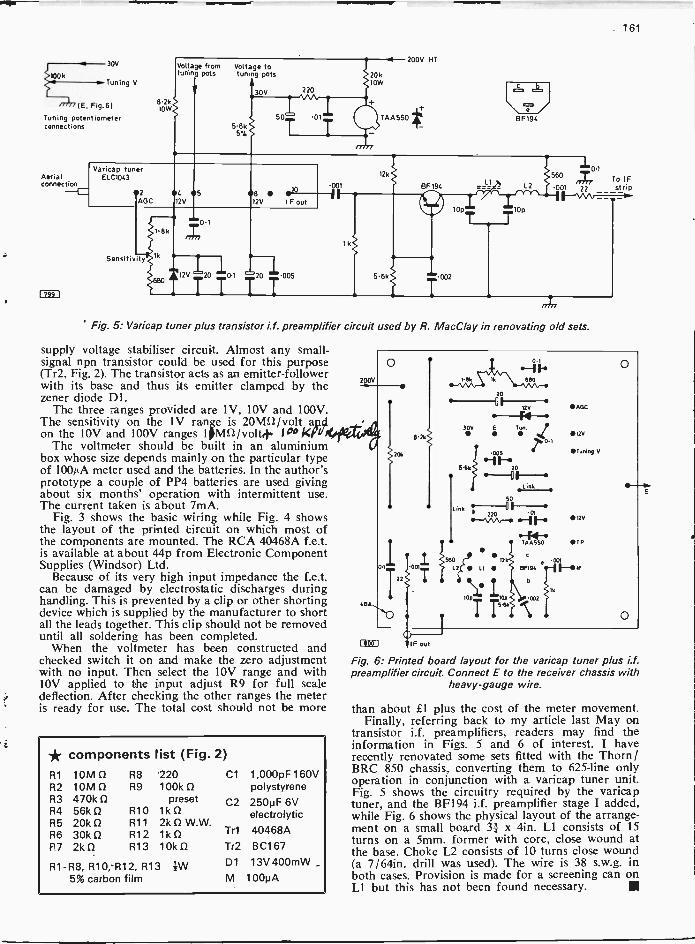
Fig. 5: Varicap tuner plus transistor i.f. preamplifier circuit used by R. MacClay in renovating old sets.
supply voltage stabiliser circuit. Almost any small -signal npn transistor could be used for this purpose(Tr2, Fig. 2). The transistor acts as an emitter -followerwith its base and thus its emitter clamped by thezener diode Dl.
The three ranges provided are 1V, 10V and 100V.The sensitivity on the 1V range is 20MS/ /volt aptdon the 10V and 100V ranges 1/MS2/volt4. fp° Wu
The voltmeter should be built in an aluminiumbox whose size depends mainly on the particular typeof 100µA meter used and the batteries. In the author'sprototype a couple of PP4 batteries are used givingabout six months' operation with intermittent use.The current taken is about 7mA.
Fig. 3 shows the basic wiring while Fig. 4 showsthe layout of the printed Circuit on which most ofthe components are mounted. The RCA 40468A f.e.t.is available at about 44p from Electronic ComponentSupplies (Windsor) Ltd.
Because of its very high input impedance the f.e.t.can be damaged by electrostatic discharges duringhandling. This is prevented by a clip or other shortingdevice which is supplied by the manufacturer to shortall the leads together. This clip should not be removeduntil all soldering has been completed.
When the voltmeter has been constructed andchecked switch it on and make the zero adjustmentwith no input. Then select the 10V range and withlOy applied to the input adjust R9 for full scaledeflection. After checking the other ranges the meteris ready for use. The total cost should not be more
* components list (Fig. 2)R1 10MR2 10MR3 470k0R4 56k 0R5 20kR6 30kP7 21d)
R8 220R9 100k
presetR10 1kDR11 2k f2 W.W.R12 1k0R13 10k0
R1 -R8, R10, -R12, R13 fW5% carbon film
C1 1,000pF 160Vpolystyrene
C2 250pF 6Velectrolytic
Tr1 40468ATr2 BC167
D1 13V 400mW
M 100pA
Fig. 6: Printed board layout for the varicap tuner plus i.f.preamplifier circuit. Connect E to the receiver chassis with
heavy -gauge wire.
than about £1 plus the cost of the meter movement.Finally, referring back to my article last May on
transistor i.f. preamplifiers, readers may find theinformation in Figs. 5 and 6 of interest. I haverecently renovated some sets fitted with the Thorn /BRC 850 chassis, converting them to 625 -line onlyoperation in conjunction with a varicap tuner unit.Fig. 5 shows the circuitry required by the varicaptuner, and the BF194 i.f. preamplifier stage I added,while Fig. 6 shows the physical layout of the arrange-ment on a small board 31 x 4in. Ll consists of 15turns on a 5mm. former with core, close wound atthe base. Choke L2 consists of 10 turns close wound(a 7/64in. drill was used). The wire is 38 s.w.g. inboth cases. Provision is made for a screening can onLl but this has not been found necessary.
162
THESILICONVIDICON)
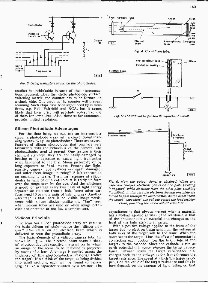
IF we were designing a TV system from scratch andhad just started thinking about how a TV camerashould work there is little doubt that we would startby taking a very close look at the human eye. Fig. 1shows the basic features of the human eye. There isa lens whose focal length can be adjusted by a setof muscles (the ciliary muscles), enabling us to adjustour vision equally to near or far objects; an iriswhich adjusts the amount of light passing through;and most important of all a retina which is a light-sensitive surface from which a "cableform" of nervesstarts out to the brain. We can imitate the variablefocus and the iris actions easily enough, but the pro-cesses that take place in the retina are neither soclearly understood nor easily imitated.
The Human EyeAs far as we know at present the retina is not a
continuous surface but is composed of sets of pieces(called "rods" and "cones" from their shape) oflight-sensitive material. Light produces a chemicalchange in these elements. This in turn results in avoltage, which is communicated by the nerves to thebrain, being generated. The brain acts as the systemcomputer. There are additional complications con-cerned with colour vision and the use of differentelements in bright light and in dim light but theseare not essential to the formation of an image whichis the purpose of television.
Each element in the retina seems to have a sepa-rate connection to the brain. Thus no scanningaction takes place in the eye though large scenes arescanned since only a small area of a scene is inactive focus at any one time. Whether scanningaction takes place in the brain we are not at presentsure, but there is some evidence that it may do sincelight which flickers at certain frequencies can causeremarkable illusions of colours and images, as if a"beat" effect of some sort is taking place.
The first step in imitating the eye would be toconstruct a "retina", and the best devices to usewould be silicon photodiodes. Such a photodiodeconsists of a pn junction which is reverse biased andconducts when light falls on it. The conduction isdue to the generation of electrons and holes frompreviously neutral atoms as a result of the action ofthe light.
ScanningWe next have the problem of using the informa-
tion from each photodiode. Since we have to trans-mit TV pictures as a modulated waveform we requiresome sort of scanning to convert our picture infor-mation into a sequentially varying waveform. The
AN SINCLAIR
scanning could be done by switching each photo -diode in turn to an output cable as shown in Fig. 2.If we were content with a low -bandwidth picturesuch as Baird's original 30 -line system such an "eye"would be comparatively easy to make though some900 diodes would be needed to get a square pictureof equal vertical and horizontal resolution. Theswitching is a problem. It would be carried out bestby means of a ring counter actuating a set ofswitching transistors (Fig. 3) so that each time apulse is applied to the input of the counter a switchcloses (i.e. one of the switching transistors conducts)and the previously closed switch opens. Even witha 30 -line resolution this is a formidable piece ofwiring: the difficulties of making such an "eye"with 625 -line resolution are apparent.
Nevertheless integrated circuit techniques are be-ing developed for this purpose. The problem is notthe difficulty of forming so many elements but ofensuring that the switching is 100% reliable. To havethe photodiodes on one chip and the switching on
Ciliary muscleCornea
Lens
Aqueoushumour
Iris
Vitreoushumour
Retina Opticnerve
Fig. 1: Horizontal section of the human eye. The aqueousand vitreous humours are liquids of slightly different com-position which preserve the shape of the eye and act with
the lens in refracting light to the retina.
rsA
WNW
Switch
sZN
o
Met
AN21/4
Photo -diodes
Out put
Fig. 2: A crude method of switching a photodiode array.
163
Photodlodes
Switchingtransistors
Drivepukes
Ring counter
Rl
OutputVO
Leto(
Fig. 3: Using transistors to switch the photodiodes.
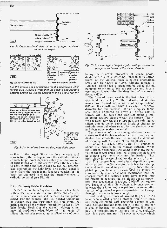
another is unthinkable because of the interconnec-tions required. Thus the whole photodiode surface,switching matrix and counter has to be formed ona single chip. One error in the counter will preventscanning. Such chips have been announced by variousfirms, e.g. Bell, Fairchild and RCA, but it seemslikely that their price will preclude widespread useof them for some time. Also, those so far announcedprovide limited resolution.
Silicon Photodiode AdvantagesFor the time being we can use an intermediate
stage: a photodiode array with a conventional scan-ning system. Why use photodiodes? There are severalfeatures of silicon photodiodes that compare veryfavourably with the behaviour of the camera tubephotocathodes used at present. One feature is theirchemical stability: they are not easily damaged byheating or by exposure to excess light (rememberwhat happened to the first Moon pictures?) or bylong exposure to fixed images. Present day light-sensitive camera tube surfaces are easily damaged,and suffer from image "burning" if left exposed toan unchanging scene. Then the response of silicondiodes to light of different colours is fairly uniformover the range seen by the eye. And the efficiencyis good: on average every two units of light energyseparate an electron from a hole (some other sur-faces need 10 or more units of light energy). Anotheradvantage is that there is no visible image persis-tence with silicon diodes-unlike the "lag" seenwhen vidicon tubes are used or when image orthi-cons are operated at too low a temperature.
Vidicon PrincipleTo scan our silicon photodiode array we can use
the basic vidicon principle-hence the "silicon vidi-con." This relies on an electron beam which isdeflected to scan the photodiode array.
The basic elements of a vidicon camera tube areshown in Fig. 4. The electron beam scans a sheetof photoconductive / sensitive material on to whichan image of the scene to be televised is projectedby means of a lens. A voltage is applied across thethickness of this photoconductive material (calledthe target). If we think of the target as being dividedinto small sections, each will be found to behave(Fig. 5) like a capacitor shunted by a resistor. The
Base Cathode Grid
811
Electron beam
Electronbeam
Anode
Lightfromlens
'4-Glass
plateface -
Photosensitive Conductivelayer layer
Fig. 4: The vidicon tube.
Photosensitive layer
Conductive coating
C
R
Mesh
Glass
Fig. 5: The vidicon target and its equivalent circuit.
Electron beam Displacedelectrons
Target'capacitors.
812 1
Loadresistor
Fig. 6: How the output signal is obtained. When anycapacitor charges, electrons gather on one plate (makingit negative) while electrons leave the other plate (makingit positive). In this case the electrons leaving one plate areforced to pass through the load resistor. As the beam scansthe target "capacitors- the voltage across the load resistor
varies, providing the video output waveform.
capacitance is that always present when a materialhas a voltage applied across it; the resistance is thatof the photoconductive material and changes as thelevel of the light striking it varies.
With a positive voltage applied to the front of thetarget but no electron beam scanning, the voltage atboth sides of the target will be the same. When thebeam scans the target it has the effect of momentarilyconnecting each portion (on the beam side of thetarget) to the cathode. Since the cathode is run atearth potential this action charges the target capaci-tance. Between scans the target capacitance dis-charges back to the voltage at the front through thetarget resistance. The speed at which this happens de-pends on the value of the target resistance and this inturn depends on the amount of light falling on that
164
Electron beam
DI I
Silicon dioxidep -type 'islands'
n -type substrate
Depletionregion
Fig. 7: Cross-sectional view of an early type of siliconphotodiode target.
material n material
0s00e e 10
G00
I 8151
0 C)0000, 0
+
00eeo
5 holes iDepletIoniOelectronsattracted i layer iattractedto -ve to +vepotential potential
(a) Junction without bias (b) Reverse -biased junction
Fig. 8: Formation of a depletion layer at a pn junction whenreverse bias is applied. Note that the positive and negativecharges shown are excess charges in the p and n regions.
eeeoElectrons in beam combine withholes in the p region to restorethe negative charge of the player. This in turn knocks someelectrons out of the n layer,giving the video output current
0CEO
00 Holes generated
by light movingto the p layerwhich has beenchargednegatively
Fig. 9: Action of the beam on the photodiode array.
section of the target. Since the time between eachscan is fixed, the voltage (above the cathode voltage)at each target point depends entirely on the amountof light falling on it; the current which the beam hasto pass to bring the target back to cathode potentialalso depends on the light level. The output signal istaken from the target front face and consists of thebeam current used to charge the target elements tocathode potential (see Fig. 6).
Bell Picturephone SystemBell's "Picturephone" system combines a telephone
with a TV camera and receiver (both miniaturised)so that a caller can see and be seen by the personcalled. For the camera tube Bell needed somethingof vidicon size and resolution but free from themain defects of the vidicon, especially its lag at lowlight levels. Replacing the normal vidicon targetmaterial (antimony trisulphide) with an array ofsilicon photodiodes seemed an excellent way of com-
(a)
EtycLco/
caocsoisioas
Goldcoating
1.0
4
Beam -4.=
(b)
n
p type
Gold
Silicondioxide
1817
Fig. 10: In a later type of target a gold coating covered thep regions and most of the silicon dioxide.
bining the desirable properties of silicon photo -diodes with the easy switching (through the electronbeam) of the vidicon. Since a silicon photodiodearray can be heated to 400°C without damage, a"vidicon" using such a target can be baked duringpumping to ensure a low gas pressure and thus avery much longer tube life than that of a conven-tional vidicon.
The form of target used in the first tubes of thistype is shown in Fig. 7. The individual diode ele-ments are formed on a wafer of n -type silicon0-05mm. thick, with an 0-1mm. thick edge of 21-5mm.diameter for reinforcement. Within a square targetarea (sides 12-8mm.) an array of p -type dots isformed with 660 dots along each side giving a totalof about 436,000 diodes within the square. The n -type regions between the p -type dots are oxidised tosilicon dioxide which being an insulator charges tocathode potential when struck by the electron beamand then stays at that potential.
The diameter of the scanning electron beam ischosen so that the beam when focused covers severaldiodes: this avoids the need to line up the directionof scanning with the sides of the target area.
In action the n -type layer is run at a voltage ofabout 10V positive to the vidicon cathode. Whenthe electron beam scans the target it fixes the poten-tial of the p -type areas (and the silicon dioxide layer)at around zero volts with no illumination. Thuseach diode is reverse -biased to the extent of about10y. This reverse bias results in a depletion regionat the pn junction (i.e. a region with few free chargecarriers) in the usual way (see Fig. 8). Since the de-pleted pn junctions are surrounded by layers ofcomparatively good conductor (remember that thecharges from the depleted parts have moved intothe remaining regions) the pn diodes act as capaci-tors-the capacitance is around 2,000pF per squarecm. Because of this the voltage difference presentbetween the n -layer and the p -islands remains afterthe scanning beam has passed-provided the leakagethrough the diodes is low enough.
Diode leakage currents of around 0.1pA (10-13Alhave been quoted, giving a storage time of at leastone complete frame with negligible change of vol-tage. Surface leakage from one p island to anotheris smaller because the voltage difference, if it existsat all, is normally much less and the silicon dioxidelayer is a good insulator. The reverse voltage which
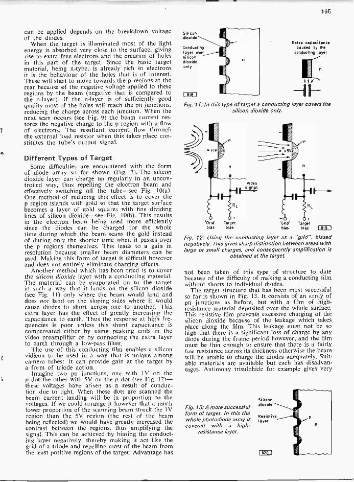
165
can be applied depends on the breakdown voltageof the diodes.
When the target is illuminated most of the lightenergy is absorbed very close to the surface, givingrise to extra free electrons and the creation of holesin this part of the target. Since the basic targetmaterial, being n -type, is already rich in electronsit is the behaviour of the holes that is of interest.These will start to move towards the p regions at therear because of the negative voltage applied to theseregions by the beam (negative that is compared tothe n -layer). If the n -layer is of sufficiently goodquality most of the holes will reach the pn junctions,reducing the charge across each junction. When thenext scan occurs (see Fig. 9) the beam current res-tores the negative charge to the p region with a flowof electrons. The resultant current flow throughthe external load resistor when this takes place con-stitutes the tube's output signal.
Different Types of TargetSome difficulties are encountered with the form
of diode array so far shown (Fig. 7). The silicondioxide layer can charge up regularly in an uncon-trolled way, thus repelling the electron beam andeffectively switching off the tube-see Fig. 10(a).One method of reducing this effect is to cover thep region islands with gold so that the target surfacebecomes a layer of gold squares with fine dividinglines of silicon dioxide-see Fig. 10(b). This resultsin the electron beam being used more efficientlysince the diodes can be charged for the wholetime during which the beam scans the gold insteadof during only the shorter time when it passes overthe p regions themselves. This leads to a gain inresolution because smaller beam diameters can beused. Making this form of target is difficult howeverand does not entirely eliminate charging effects.
Another method which has been tried is to coverthe silicon dioxide layer with a conducting material.The material can be evaporated on to the targetin such a way that it lands on the silicon dioxide(see Fig. 11) only where the beam would land anddoes not land on the sloping sides where it wouldcause diodes to short across one to another. Thisextra layer has the effect of greatly increasing thecapacitance to earth. Thus the response at high fre-quencies is poor unless this shunt capacitance iscompensated either by using peaking coils in thevideo preamplifier or by connecting the extra layerto earth through a low-pass filter.
The use of this conducting film enables a siliconvidicon to be used in a way that is unique amongcamera tubes: it can provide gain at the target bya form of triode action.
Imagine two pn junctions, one with 1V on thep dot the other with 5V on the p dot (see Fig. 12)-these voltages have arisen as a result of conduc-tion due to light. When these dots are scanned thebeam current landing will be in proportion to thevoltages. If we could arrange it however that a muchlower proportion of the scanning beam struck the 1Vregion than the 5V region (the rest of the beambeing reflected) we would have greatly increased thecontrast between the regions, thus amplifying thesignal. This can be achieved by biasing the conduct-ing layer negatively, thereby making it act like thegrid of a triode and repelling most of the beam fromthe least positive regions of the target. Advantage has
Silicondioxide
Conductinglayer oversilicondioxideonly
I me I
Extra capacitancecaused by the
conducting layer
Fig. 11: In this type of target a conducting layer covers thesilicon dioxide only.
'Grid'bias
n
Targetbias
Videosignal
Fig. 12: Using the conducting layer as a "grid", biasednegatively. This gives sharp distinction between areas withlarge or small charges, and consequently amplification is
obtained at the target.
not been taken of this type of structure to datebecause of the difficulty of making a conducting filmwithout shorts to individual diodes.
The target structure that has been most successfulso far is shown in Fig. 13. It consists of an array ofpn junctions as before, but with a film of high -resistance material deposited over the whole surface.This resistive film prevents excessive charging of thesilicon dioxide because of the leakage which takesplace along the film. This leakage must not be sohigh that there is a significant loss of charge by anydiode during the frame period however, and the filmmust be thin enough to ensure that there is a fairlylow resistance across its thickness otherwise the beamwill be unable to charge the diodes adequately. Suit-able materials are available but each has disadvan-tages. Antimony trisulphide for example gives very
Fig. 13: A more successfulform of target. In this thewhole photodiode array iscovered with a high -
resistance layer.
Silicondioxide
Resistivelayer

166
good results but as it cannot be baked at high tem-peratures one great advantage of the silicon diodetarget is lost. Gallium arsenide has good propertiesbut the films are not consistent. Other materials arebeing investigated.
PerformanceThe performance of the silicon vidicon is certainly
superior to that of the conventional vidicon. Thesensitivity in terms of µA signal for µW of lightenergy is better and remains constant with illumina-tion level changes. This corresponds to a gammavalue of about 1 compared to a standard vidicongamma of 0.6. (Gamma is a way of stating the rela-tion between light in and signal out. It can be definedas log [signal out/signal in], unity gamma being oneway of stating that the silicon vidicon's response islinear.) The response to colours is wider than thatof the conventional vidicon and extends much fartherinto the infra red region.
The resolution obtained depends not only on thenumber of diodes in the array but also on the resistivefilm used to cover them. The resolution is adequatefor 625 -line use.
Diode faults cause defects in the received picture.The way in which these faults affect the pictureseems to depend on the resistance of the resistivelayer used to cover the target. With a comparativelylow -resistance layer a defective diode appears as awhite spot. With higher -resistance layers however thewhite spot starts to spread at high target bias vol-tages and will eventually blot out the completepicture. It seems that one defective diode in half amillion will cause this "white -out" effect if a high -resistance layer is used with a high target voltage.
Unlike the antimony trisulphide vidicon the siliconvidicon is very stable chemically. The target can bebaked at 400°C during tube processing without lossof any of its performance and this enables siliconvidicons to be pumped to a lower pressure, and withless absorbed gas present in the structure, than isthe case with an antimony trisulphide vidicon. Thereward for this lower gas pressure is a longer activelife while the chemical stability of the target shouldmean that the electrical characteristics of the targetdo not change with time.
A valuable property is the lack of "burn -in" orpermanent image due to scanning the same area fora long time. It has been customary with conventionalvidicons and image orthicons to overscan the targetduring warm-up so as to avoid excessive scanningof the same area: in colour cameras this requiressome re -registration before transmission so thepractice is less common. The only change that occursin a silicon vidicon seems to be a change in thediode back resistance at certain values of reversevoltage.
The image lag with an antimony trisulphide vidi-con is due to the time taken for electrons and holesto recombine, so reducing conductivity. In a siliconvidicon this time is around 10,4sec or less so thatlag due to this effect is negligible. As with anycamera tube some lag can be detected if the beamdoes not completely discharge the target: with thesilicon vidicon this is very much less than the lagexperienced with the conventional vidicon.
Finally, though the tube is at least as sensitive asany other vidicon it is not damaged by intenseillumination: the Bell Telephone Laboratories re-
port having focused an image of the mid -day sunon to the target of a silicon vidicon tube withoutdamaging it.
The main impact of the silicon vidicon so far hasbeen for low light level surveillance applicationswhere its sensitivity is the great advantage. For thepresent the Plumbicon (lead -oxide target vidicon)seems to have established itself as the standard tubefor modern studio colour TV cameras. Silicon vidi-cons have been added to the ranges of camera tubesavailable from several manufacturers. Mullard forexample state that their silicon vidicons are directreplacements mechanically for their standard vidi-cons and require very little modification to thecamera circuitry: the electron gun used is the sameas in Mullard Plumbicon tubes.
As we saw earlier the basic silicon photodiodearray is the key to the next major development in TVcameras, the miniature all solid-state camera. Forthis purpose the array will be allied with a charge -coupled i.c. arrangement to provide the output signal.We shall be reporting on this later. Meanwhile thesilicon vidicon itself is a most interesting collabora-tion between solid-state and vacuum techniques.
LETTER
Awkward Field FaultI have just spent a considerable while trying to findthe cause of a field fault in a receiver fitted withthe BRC 1500 chassis. The symptoms were asfollows. To start with the field scanning wouldappear to be correct, but with a jitter. The bottomwould then start to fold up rapidly until the scanoccupied only a small band across the centre of thescreen. By advancing the brightness control the fieldblanking pulses could be seen above the folded overscan. Alteration of the height control would bringback correct scan for a short while. This looked likea height circuit fault but everything proved to becorrect there. Eventually the fault was found to bethe result of failure of the timebase to oscillate asR102 (see Fig. 1) in the cross -coupling network
Fig. 1.
001.7
liV3A V3B'022
between the anode of the pentode section of thePCL805 and the grid of the triode section hadincreased in value from 18kS2 to 400kS2. To be onthe safe side I replaced both this and R101 using1W carbon film resistors and that cleared the fault.
It may help your readers to know of this possiblecondition.-A. M. Levett (Portslade).

168 169
rof 11111 HMI /1 MDR CF 111/1/01.11111S WWI MY MHO! I111f1 MU$1117011 Of 1011S SOX IN MOH 1/11151 IllgiffS COINVIN WW1 HMI
4101111 Nal $(010110.4101041101040/0 SI AANTENNA Lmf 1+ iiA/EllII 5005NOELS
iV.,-kV
cIffIRnitlga"11/ 1 or MHOS IN PHIOf 15/Ill/f SICJII-1.
1022-
-115 1 I
fitof -CAP -
moor
-V/44103
112211L115161FIIC214
_-_lL105
6140?0111 CAILE ASST.
LIR 7
VHF TUNER 946363-5SIC .-S42
4101.004v
I n121 111E1"
40 SID 4310/611N11E16110 TIARA
LIB
L115
LII4
tI
1_106
LI07
r3
0115
3HA5VHF AMP
viOf
1121
10
SIEOSC waif.
LI1171 Lp
1110
141
I3 'nomO.
1.142
LI
1/1611
132,39Lf21
111,i/s61 21S
cs(42FTil_.,.,..
FINE-
5z71.2 1132.:ppi° CI*
""i5
12 "3
1 50
LII9
7 "3-, ZCIIT11110101 ?j 50
.'111034/I
IC11070 2- 0115
0 0
__0133
1.2241
R1051.21
.4111
IS
I(IC00.111
1110
1/25G57yvH.F.NgER
L122
1000
fI IIjj 22( T"
L124 111
0121
10
I1.21001214
T
101100C115
.T1NFO V, 7:4 .4 -151116
R1
111056
UHF TUNER 946361-3r -L151-17 __Tec
If201 rHSI11121
L152"ITO,
C150_1_ 1113
tvg,loo -r -1.31
10152 V4'-,420
I051
T100
Ills I
1,11 I VP LI53
111 1111 SINE Hat IS NOM.
I51 UNE LIIIIt.
.11f
riiiiiiNFLillf- - - -
CI3k__ig+
_CM14
93A59-1 1
114152.06
1I
IIT" 011411(1
CR151
OSC 1140CISIC
57B2 1- 5UHF 0500151
C153-/0
the modifications on the electrical side.If the tuner unit is found to have a balanced
input it is necessary to fit a balun operating in thereverse direction to convert the incoming 750 line to3000. Baluns are not too easy to come by but onceone has a conversion facility set up a balun removedfrom one receiver can be reinstated in another. Such"recycling" is of course very efficient!
Since the v.h.f. facility will not be used in the UKthere is no need to change the v.h.f. aerial connec-tions. In some cases however it may be convenient
1/25GS70111 OSC.
110213 Cili
WW1( WES'r 11115/S nomi NO/ 10mIll II MORON VHS SHIM
WHY Nil HO S!///IC X CON1101SMPS MI 1/I till IOC coodorotYHVH/1 1/y01,21201 HMS 071111151 /10111111IC poi fief$ 1111 MHO II 1101 it I/11 NO SIClIi.1/21 /WWI I 114411131 I NH 101541f "'HRH
PIO NOW II WOW Of PIECIR011 XIX PPM
1201
HAI VIII Of CONTROLS
1-31-Tas- 115 331F15552 l
I VIOl 1/102 cm I
0 0C
L 19 0 0 woo1
I
L _ _ _ l000i 1
120
_I
LEAD VIII OfL301 EL L302
511s4.0(0010"Gb11,
0 07a.FS NOT SIX Of 1101 X S5014
ED=
111; ff COI?IIIIN! PSODICIlf/ffr
-045 5110011
12000.ti:511.451 zifl m7,021011102'
II
;51
a:8_574211_Pyj0501 93
1- _ 14QUICK PUT DIODE
CR502
1011111
-4-
1413Rt11302
C315 8BM1111.181120
33GY7A 23290201 0403 V401
1/314BRII/0/40111111
v3020 0201
220 _ _ _ 4 SIC
-.6 V 'COQ L20IA L20191
I Ss
L.
1/28BM I I15111V3018 In
302 .....0303 130411101 224
'/314BR11ICC
0302CII
C431
I001114431
15015.5 1411111511110
931352-1SILICON InTinER t L501
Oil 0003 41
-/1,, 110411
CR501 ___L0502 1306 511
A, )(T.-7145031 c 05031 46.7. C503C _L,111 250144 4.20044 SONS
ION 1502 .. 150V own -
00--C411 300
3 xi VVIt%
68LT8HOC/ PHASE DVV4020
INF
I/2 EztF03J111 1 1
030113 4,
j 1305
1504
1/2178F11 AWIND 5E1v201
P WS 714C424 -2O
C201 IL "Mt __I
L303 L304
0210
COlT 0301 L309
T" I
.0, .0,I
L _ 14 2NC_ -J
1304220
0311
1201
1/28LT8110112 OSC
V4028/351
.r C123
NAV 33*3s.,.121
--
1410
57111
HEIGHT I /III1.11111 NEC
10041112 TWEB
11(1415111
01241/00
Fig. 1: Circuit of a representative US,vnains-only portable using compaction valves.
to remove them entirely to make room for the u.h.f.input modifications and to avoid confusing thecustomer.
Mains SupplyOnce the aerial arrangements have been sorted out
the receiver should be fed with 220V a.c. from anautotransformer or variac and have its operatingcurrent measured on the a.c. range of an Avometer.The waveform will not be sinusoidal so the Avo
i/233GY7A10112 OUTPUT
V40305
0435LiNEC
1212ISO
VOLUME
1106eSve221
1/217BFIIA00010 0071/
12019
or
1/314BRI1VIDEO 1144.V302
4301 0.11
2
SIT MIROC117/011 11101
/4
Wt in- s
5001
1201 j
120
VERT
1201
TIM,
I
11ML10111
CII2C313--(--
' 22 J-llill51111 CI
ilpg 3L05 1211.1
IRSluul
13504
1POIN
BRIGHTNESS'
-- --'CONTRAST
/150131120
111510
010
IrI
mrlitamIDC Winglily
14161.2420
VERT. LIN J_--(1x1151 011
0014111[101 X
110
6n
IA
55018 SPOT raj10511 ELM NATION I
431 SW1TCN INT D. I
0112081. L
0411 0412
+-10-404111 .02211
517401r14094 .2.2a, MYr
I
0O15
L402
..._00.112101101111C1011111
.44371130 0,11 5.214
111 411 Nati51 5.4
C/31 1/233GY7A I17,5111
011111V0030
reading will not be accurate : this does not matterhowever -just note the reading. A series resistorshould then be fitted (trial and error being the simp-lest way) so that when the receiver is fed from 240Vthe Avo reading is the same as before. Once thecorrect resistor value has been established a per-manent home can be found for the component withinthe receiver. Remember that it will become very hot(about 20W rating may be needed): it should bepositioned well clear of heat -sensitive componentstherefore.
O
10414111111111: IllS111/011111.1111 III WWII
HMIS HUSS WHIR PEST10011IfO7li ISfI
SIT MIME CHI101.41011
Intercarrier Sound
M201SPE401(3
3.243
Still 80Y010 /TEN!HMV 11Cf Riff
!PICTURE Toll0303
°ay
5.10TOTAL
5 IIITE
i3037p4PICTURE
TUBE
SIC 5111ICE11105711/104010 111111110M010 10 CHCS/S,1100 IlSO COMMfill SIERNI010fill! 70YNf full!
11.011
1
Having completed these two operations thereceiver should be examined to find the intercarrieri.f. transformers and f.m. discriminator. Switch onand if possible tune to a test card, adjusting formaximum definition. The picture will in all prob-ability be entirely satisfactory. If there is any soundsignal at all coming through however it will beaccompanied by a loud roaring buzz.
The procedure which works out best is as follows.

170 167
12V to tunerand IF stage
From C1
100p
rim
Fig. 2 (left): Obtaining a zener-stablised 12V supply fromthe h.t. line.
Fig. 3 (right): Simple but successful single transistor i.f.amplifier which can be added to provide extra gain.
First unscrew the cores in the f.m. discriminator canand see whether the sound improves. One core (in thesecondary winding) will be found to have a point atwhich the sound improves and the buzz level dropsdramatically. Leave this core in the minimum buzzposition and adjust all the other sound i.f. cores formaximum volume. The sound will probably increasein volume as each core is moved outwards from itscoil (so increasing the frequency of operation from5-5MHz to 6.0MHz) until finally there is an abund-ance of volume. It is now advisable to wait untilthere is a break in the test card music so that thediscriminator cores can be finally adjusted forminimum intercarrier buzz. The tuning of thereceiver should be rechecked at this point and if adiscriminator balance potentiometer is fitted thisshould also be adjusted for minimum backgroundbuzz.
Once this procedure has been correctly carried outthe receiver can be finally reassembled.
UK/US OperationThe foregoing description represents the simplest
approach to Continental receiver conversion. Beforemoving to the next phase I should mention the SonyTV110 UWE portable receiver which is capable ofoperating either in the USA or on the Continent.The 5.5MHz i.f. strip is right at the top of thereceiver, being separate from the main i.f. panel, andcan easily be adjusted to UK working. The receiverwill then operate in both the UK and the USA butnot on the Continent : this arrangement is very con-venient for some regular travellers.
Adding a UHF TunerOne sometimes comes across a 625 -line receiver
with 5.5MHz sound but no u.h.f. tuner. Such setsare usually of Japanese origin and are built for usein Middle Eastern countries where u.h.f. is not yetemployed. When conversion of these receivers iscontemplated allowance must be made-in terms oftime, effort and cost-for removing the v.h.f. tunerand fitting a u.h.f. one in its place. This is quite aninvolved job and should not really be undertaken byanyone except an experienced engineer. A suitabletype of u.h.f. tuner has to be located (usually of
Japanese manufacture) and obtained ostensibly as areplacement for a UK import. Knobs and dials mustalso be obtained at the same time. Brackets andmountings need to be made up and the final job madepresentable from the appearance point of view.
As these receivers are usually valve types the heaterline has to be interrupted when the v.h.f. tuner isremoved and a resistor fitted in place of the v.h.f.tuner valve heaters. It is advisable to measure thevoltage and current required by the v.h.f. tunervalves prior to removing the tuner so that the valueof the resistor required can be calculated using Ohm'sLaw.
Any a.g.c. line to the tuner can be disconnectedand disregarded. Since the u.h.f. tuner will have lessgain than the original v.h.f. type it will probably benecessary to add a transistor i.f. stage to make up thedeficiency. The u.h.f. tuner and extra i.f. stage canbe supplied by a zener diode stabiliser as shown inFig. 2. Various i.f. amplifier circuits have been tried:one of the easiest and most successful is shown inFig. 3. Here a grounded -base amplifier stage isemployed. The r.f. choke L2 can consist of 25 turnsof 38 s.w.g. enamelled copper wire wound on to ataped ferrite core. LI consists of 15 turns of 28 s.w.g.enamelled copper wire. It is important that C3 is asmall disc ceramic capacitor with its leads kept asshort as possible, otherwise the common inductancein Trl base may result in the circuit being unstable.
This particular type of job is very expensive forthe customer, and a valved receiver made in Japanis likely to include valves which are unobtainable inthe UK. Where do you obtain a 17JZ8 for example?This valve is a triode pentode, performing the samebasic functions as our PCL805. I have succeeded inobtaining valves from Japan but there is a delayunless they are flown in and then they are expensive.These points should always be explained to the cus-tomer. I mentioned this before but stress it again.
US SetsWe next come to the American TV ("the man in
New York said it would work anywhere"), boughtcheaply from a chain store and brought home to theUK. Fortunately most people realise that a trans-former is needed to reduce the mains voltage to110V. So they buy such a transformer and then findthat they can obtain hardly any results from the set.
TimebasesLooking at Table 1 again, it will be seen that the
US system uses a line frequency which is almost thesame as ours, so there are no troubles with the linetimebase. The number of fields is higher however-which results in only 525 lines instead of 625. If weslow the field scan down frbm 60 to 50 per second wecan receive a 625 -line picture to our standards. Thereis usually sufficient latitude on the field hold controlto enable this change to be made by simple adjust-ment. If this is not possible increasing the value ofthe resistor in series with the field hold control willprovide the answer.
TunerFortunately it is now mandatory in the US that all
receivers are fitted with a u.h.f. facility. As the US
KEITH CUMMINS
puniiiiimomommummimumummimmumiummiumminimummummummiiimmmummininogiP * * ******* *1*****7**
******1* * *
CONVERTING FOREIGN TV SETSEVERY so often a customer will bring us a tele-vision receiver which he has purchased abroad. Thecustomer is usually totally unaware of the differencesin the TV standards used in different parts of theworld. On hearing about this he is often in a stateof some anxiety, having purchased the receiver andperhaps paid import duty only to find that he has atelevision set that will not work in the UK. It ispossible as we shall see to modify foreign receiversto operate satisfactorily in the UK, but the cost ofdoing so varies considerably.
TV Systems in UseLet us first consider the present broadcasting
arrangement in the UK. We have the old v.h.f.405 -line monochrome transmissions and the u.h.f.625 -line colour system operating side by side. As the405 -line system with its a.m. sound carrier is peculiarto this country any conversion to this system mustbe considered uneconomic and pointless in the longterm as the 405 -line system is to be phased outduring the next decade. Conversions can only sen-sibly be considered therefore in terms of the 625 -linesystem. The basic parameters of the three majorTV systems in use today are shown in Table 1. Thefeatures shown describe basic monochrome opera-tion-colour will be considered later.
Continental SetsIt will be seen that the differences between the
Continental and UK systems are minimal, the maindifference being the intercarrier sound frequencywhich is set of course by the sound -vision spacing.It is the practice on the Continent to use the lowerTV bands for 625 -line transmissions (there is no dual -standard working except for the 819 -line monochrometransmissions still used in France) and sets are fittedtherefore with both v.h.f. and u.h.f. tuners. For 'OKworking the v.h.f. tuner has to be parked in the "U"position and the intercarrier frequency changed to6MHz. All the other parameters are compatiblesystemwise. The continental receiver will be fittedwith two IEC type 30012 balanced line aerial inputsockets, one for v.h.f. and the other for u.h.f. It willalso be designed for 220V 50Hz a.c. mains working.
We can now list the changes which need to bemade to the continental receiver so that it will
operate in the UK. First we have to change the aerialsocket to a suitable coaxial type. Secondly we mustaccommodate the change in mains voltage from220V to 240V. Thirdly the intercarrier i.f. stageshave to be retuned.
Advising the CustomerBefore commencing the operation the customer
must be informed that the process is one way, i.e.that the set will be unsuitable for use with the originalsystem once the modifications have been completed.If there is any chance that the set is likely to go backto its country of origin, the customer may simplydecide to pack it away for the duration. Anotherthing that needs to be explained is the difficultywhich could be experienced in obtaining spares (e.g.the line output transformer and scanning coils) inthe event of breakdown. Only if the customer is pre-pared to accept the risk should the job be under-taken.
Aerial ConnectionThe aerial connection at 30012 may well be found
to terminate behind its socket in a small ferrite -coredtransformer called a balun. This device converts the3001l balanced input to a 7511 unbalanced coaxialfeed for the tuner. If such a device is fitted it cansimply be removed and the appropriate coaxialsocket fitted in its place-a mains -isolating u.h.f.socket should of course be used. Often the mechani-cal arrangements are more difficult to engineer than
Table 1 : Characteristics of TV SystemsUSA/Canada/
Parameter UK Continent Japan!S. America
Number of lines 625 625 525Line speed (Hz) 15,625 15,625 15,750Number of fields per
second 50 50 60Sound System FM FM FMSound -vision carrier
spacing (MHz) 6 5.5 4.5Bands used IV and V All AllOverall channel
bandwidth (MHz) 8 7 or 8 5

171
channels are narrower than ours the highest channelnumber on the tuner is 83 instead of 68. If we modifysuch a receiver therefore the channel numbers willnot tally. Fortunately this is something most peopleget used to once they know where to find the pro-grammes. The v.h.f. tuner has to be permanentlyparked at "U" and tuning carried out using the u.h.f.tuner only.
AlignmentThe awkward part of the conversion involves
changing the intercarrier frequency from 4.5MHz to6MHz. Such a change cannot be carried out byadjusting the tuning cores alone so it will be neces-sary to modify the values of the tuning capacitorsused in the intercarrier i.f. stages. This involves a bitof trial -and -error working. The simplest approachusually is to remove the capacitors from inside thecans and then solder new, lower value ones acrossthe appropriate points on the printed circuit beneaththe cans. Patience is needed here.
When the intercarrier frequency is finally alignedto 6MHz it may be necessary to stagger tune themain i.f. strip, using a test card, to obtain adequatedefinition and sound level. Certainly it will be neces-sary to locate and retune the co -channel sound trap(L301 in Fig. 1) at the input of the i.f. strip in orderto avoid buzzing on sound and attenuation of thehigher video frequencies.
Retuning the whole receiver takes time and sincethe bandwidth is increased there is an overall loss insensitivity. As the video amplifier stage is designedfor a 4MHz bandwidth it may not be able to do fulljustice to the incoming signal. It is best left alonehowever otherwise further loss of gain may beincurred.
Aerial & Power SupplyThe aerial (or should I say "antenna"?) input in
the USA is 30011 balanced, so again modification aspreviously described will be needed in order to ter-minate a 7511 coaxial feeder.
As an American receiver is designed to operate ona 110V a.c. mains supply it is best to use a trans-former to reduce our mains voltage. Suitable trans-formers are included in the RS range.
"Instant -on"Many American portables have a fast warm-up or
"instant -on" facility. The circuit of this is shown inFig. 4. Diode D1 allows every negative half -cycle ofthe incoming a.c. mains supply to be fed to theheater line when the mains on/off switch is turnedoff. This keeps the heaters in a state of semi -warmreadiness. The h.t. rectifier D2 cannot conduct underthese conditions since only negative pulses areapplied to its anode. When the mains switch is closedDI is short-circuited, the heaters rapidly warm totheir normal operating temperature and D2 providesh.t. in the usual way.
Representative CircuitThe circuit of a US portable we have recently
converted is shown in Fig. 1. It is of particularinterest in being representative of a "generation" of
110V
DI
c/o
rvti-Heaterchain--
r-rIT
T794
Fig. 4: Fast warm-up or "instant -on" circuit.
television receivers that never appeared in the UK-those employing 12 -pin compactron valves. At firstsight of the circuit the number of valves used looksnormal enough-until one realises that there areonly six valves on the main chassis, plus the e.h.t.rectifier and two v.h.f. tuner valves. Both vision i.f.pentodes share the same envelope (8BM 11); the videoamplifier pentode, gated a.g.c. triode and neutralisedtriode intercarrier sound amplifier share the sameenvelope (14BR11); the pentode quadrature sounddetector and sound output valve share the sameenvelope (17BFI1A); the sync separator triode sharesthe same envelope (23Z9) with the triode -pentodefield timebase valve; while the line timebase consistsof two compactrons, a double -diode -pentode (8LT8)consisting of the flywheel sync discriminator diodesand pentode sinewave line oscillator, and a diode -pentode (33GY7A) combining the line output valveand boost diode. So be warned what might comeyour way ! One other crafty feature : note the wayin which the field output pentode bias is derived-from the -69V established at the grid of the triodesection of the timebase via the hold and linearitycontrols and R416 to provide -16V on the controlgrid of the pentode. That could cause some headscratching in the event of bottom compression!
Colour SetsWe are sometimes asked to consider converting
colour receivers. A great deal of complexity is in-volved in this so SECAM and NTSC receivers aredefinitely "out". Continental PAL type receivers canbe modified using the approach already described :it is necessary to retune the sound traps in both thei.f. and chrominance sections however in order toavoid objectionable sound-chroma beat patterning.As the colour subcarrier frequency is the same thecolour circuits themselves need only be adjusted inthe normal way.
In the case of an NTSC receiver one would notonly have to replace the decoder circuit with a PALdecoder and take care of the attendant interfacingproblems but would also have to replace the tunerand i.f. strip because of the narrower US channelbandwidth (with the colour subcarrier at 3.58MHzinstead of 4.43MHz). In view of the critical import-ance of the i.f. response to a colour receiver's per-formance it would be quite uneconomic to try tomake modifications here.
ConclusionThe purpose of this article has been to provide
guidance on receiver conversions : really howeverthese have to be played "off the cuff" as each situa-tion arises. Nevertheless if the basic approach isunderstood, and the differences between the variousTV systems fully appreciated, completely satisfactoryconversions can be carried out. Unfortunately theywill always, inevitably, be expensive.
172
John Law
BRC
1400 CHASSIS -2
Line Output Stage FaultsTimebase valves in any set are suspect and
multiple ones are more prone to faults. Apart fromvalves a common fault which gives normal receptionon 625 lines but line collapse on 405 is failure ofC106 (600pF, 2kV working) or C108 (03µF, 150Vworking). In one case leakage in C106 resulted inline tearing and arcing. In another case line failureon 405 lines only was due to C55 in the line oscilla-tor circuit being faulty-this also results in thePL504 overheating of course. The coupling capacitorC117 to the line output valve can produce varyingline troubles depending on the extent of the leak.This fault also means an overheated PL504.
Line collapse on 625 only occurs when C107 goesopen -circuit.
Another weak spot in the line output stage is the8kV working capacitor C114. This tends to result ininsufficient width. Lack of width has also beentraced to changes of value of R140 and R141 inthe PL504 grid circuit, the width control R142 trackbeing open -circuit or the resistor R143 in series withit changing value. A low -emission line output valvealso gives this symptom of course. An unusual caseof low width which could be expanded by pressureon the e.h.t. tray was eventually traced to the wrongtray having been fitted : as mentioned before thereare different types of trays which are not inter-changeable. Leakage in C113 which feeds pulses toZ4 can damage this v.d.r. resulting in low widthafter C113 has been replaced. C113 by itself cancause lack of width: it can also when faulty result indamage to the e.h.t. tripler.
Absence of e.h.t. can be due to failure of theboost reservoir capacitor C105. It can also be causedby the smoothing capacitor C104 being defective(make sure it is a 1/1F type, rated at 500V, ratherthan 0.1/4F as fitted in some receivers). Failure ofthe boost supply after an hour's use was traced tothe boost reservoir capacitor breaking down: oncooling it resealed and gave a further period ofnormal operation. Another cause of no e.h.t. isfailure of the line output valve screen grid resistorR138: this leaves the oscillator working and thegrid drive normal. If the associated decoupler C115is suffering from loss of capacitance striations willappear on the right-hand side of the raster.
Line Oscillator TroublesLoss if line hold with a change of note turned
-ISLA to be a mechanical fault: the screened cablewhich feeds the grid of the line oscillator-fromtags 4 to 5 on the panel-was shorting. No lineoscillation has been traced to R69 in the line oscilla-tor grid circuit changing value, the associated timingcapacitor C53 being leaky and also to a faultyblocking oscillator transformer (T1). Note thefusible resistor R145: if this opens, the h.t. supplyto the line output stage and line oscillator is re-moved. This resistor is not present in earlier versionsof the chassis.
Line hold controls at the ends of their tracks canbe due to the d.c. amplifier cathode voltage beingincorrect: the cathode is biased by a potential divi-der and the trouble occurs when the upper resistorR59 changes value. The first suspects in the eventof line sync troubles however should be the flywheelsync discriminator diodes W5 and W6, followed bythe d.c. amplifier valve V4B.
A leak in C43 which increases as temperaturerises can result in poor sync after an hour or so. Insome sets it helps to add a 100pF capacitor inparallel with C43.
R59, R60, R62 and R69 can all change valueintermittently to produce line drift.
Wavy VerticalsHum on the line, i.e. wavy verticals, can he A.,
caused by loss of capacitance in the main smoothingblock: it is better to replace the complete canrather than add external capacitors. This symptomis also caused by the same fault in C52"which de -couples the h.t. supply to the line oscillator and d.c.amplifier.
The associated smoothing resistor R66 can in-crease in value: its appearance is a good guide toits condition as it generally discolours considerablyas its value alters. It is located at the bottom leftcorner of the panel and the fault symptoms it pro-duces include line waver and slip. When C52 driesup the general line instability is aggravated. Theoriginal resistor is a +W type: replacing it with a1W type will avoid the fault developing at a laterdate.
Fuzzy PictureA fuzzy picture with no control of focus was
caused by a break in the lead to pin 4, the focus
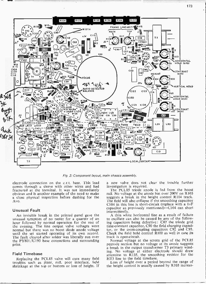
173
VIO
41439
C42
[36
250CFC,73 R14011
MEW
741 C IldC107 Z4
DEO LIEU LI1X1 El=1
R131) Ws...41°
0125
W12W12A -E
C109CI 10CIIIC 112
0
R56C.1
C I15
RI 34 e
O.OH
T4
24.R621.
So ;1;,01)
B
41.C116
iiRI43
41°'sDEB
VII
IIL35
1/C88
C104RZ.2_2 20.=!°21
R 2
4
29
2:
RI32
RI3
0 CIIJ7
C53 111114t71 C3870
R38
PAWR43
V6
c
R142
/WIDTH034 CII;
RI24C100
R123
C IOQ
CIOJ
11128 o/8
.1../121 Ram
C39
R41
C35
47/
FOCUS
FRAME LINEARITY11114 5
MAIN TOP 71
R118
25 °
°JO
.1:kRATIO DETECTOR
88 BALANCE
/9
36
L 2.5 /2 el R73 C 5CF3Cr4117.9604,/ I
979 77
C62)C60
.R76Ra7
/6
C98RII6
RII4-I R111 R113C97 Rios_nri to
RIlagat [r12u 972
Par9 -C90
C93
440
045
C106 C-1 5-13- .7P3E8-g "
C6476._
VS ...e37 C65/69 C71/73W7/9
C34 CA39
R R86
. V7 s..
L23/24 L5/6C18 CI9 C56
C8
-- C44 -Rai= =75- -R85 - - - R75 "Mai - - 28! -75 - - -52JIL/-' owl= LE=1 K = HI= G= F= ,c= CC= B= A= :1Lt- C43' - -R33001 R32. 79rf,5R58= - -
7 C4 L__3 ciaL617 oF R89.7 C21 7 C7LJ - RIO1,:3
twy.;s= ____ 4 NA cq I 013LIB
RI-21MC61114.R77° LI 30-T° rt6tC7 R./.4. irgrpti
C80° '1C85 . 442
ys 196
04
4D
R6751111C12711:2
T2
L9/IIL14/16
R27/2130R30
.C27/213.C30/31W3/4
Fatit
R97
L7/8 C22 .C23. r 0
R60 Ci26C 244 4.2 4R
5296 R25
L3/4 C IIC12 .
,2 2. w vw 2 C214....4
51 102 L0714 *R12
R9
L1/2 C 3/B
C2
8103
HORIZONTALR6 HOLD (625)
\ CONTRAST(6251
R100
Jo Roes R63 "VERTICAL HOLD6o Ob..
C16
IMo2
W I
RII
LOCAL/DISTANT
Fig. 2: Component layout, main chassis assembly.
electrode connection on the c.r.t. base. This leadcomes through a sleeve with other wires and hadfractured at the terminal. It was not immediatelyobvious and is another example of the need to makea close physical inspection before dashing for theAvo.
Unusual FaultAn invisible break in the printed panel gave the
unusual symptom of no raster for a quarter of anhour followed by normal operation for the rest ofthe evening. The line output valve voltages werenormal but there was no boost diode anode voltageuntil the set started operating of its own accord.The fault cleared after solder was liberally run overthe PY801/U193 base connections and surroundingprint.
Field TimebaseReplacing the PCL85 valve will cure many field
troubles such as jitter, roll, poor interlace, fieldshrinkage at the top or bottom or loss of height. If
C13
R65 IHORIZONTALHOLD 1405)
ERS
4
CONTRAST- 1405)
a new valve does not clear the trouble furtherinvestigation is required.
The PCL85 triode anode is fed from the boostrail. No voltage at the anode but over 200V on R103suggests a break in the height control R104 track.The field will also collapse if the smoothing capacitorC104 in this line is short-circuit (replace with a luFcapacitor as previously mentioned)-C104 can shortintermittently.
A thin white horizontal line as a result of failureto oscillate can also be caused by any of the follow-ing capacitors being defective : C87 the triode gridtime -constant capacitor, C90 the field charging capaci-tor, or the cross -coupling capacitors C92 and C93.Check the field hold control R100 as well in case itstrack is open -circuit.
Normal voltage at the screen grid of the PCL85pentode section but no voltage at its anode suggestsa break in the output transformer T3 primary wind-ing. No voltage at either electrode should drawattention to R135, the smoothing resistor for theHT3 line to the field timebase.
Loss of height over a period beyond the range ofthe height control is usually caused by R103 increas-
TP
174
ing in value. If it turns out to be in order check bysubstitution the miniature thermistor X1 in serieswith the field scan coils.
A heater -cathode leak in the PCL85 will tend tocancel the bias from the heater chain to the grid ofthe pentode section via R105. This results in bottomfold up. Leakage in the coupling capacitor C93between the triode and pentode sections of the valvegives similar symptoms.
Field linearity faults can be caused by a breakin the track of either of the linearity presets R116or. R118. If C97 is faulty the linearity will be affectedaccording to the degree of leakage. C94 and C95can go short-circuit to produce field cramping-thismay also be experienced if R135 is 1.51a2 instead of1 -7162.
Sync FaultsSync faults in this chassis seem to have greater
effect on the field synchronisation than on the linesynchronisation and to be worse on 625 lines than405. Where the sync performance is poor check thebias stabilising resistor R38 in the video amplifiercircuit: when this changes value the sync becomesvery critical. Any slight leakage in C34, the couplerto the video amplifier, or C40, the coupler to thesync separator, will affect the shape of the syncpulse: when in doubt change both. The field holdadjustment becomes very critical if the sync separa-tor screen grid voltage is incorrect. The upperresistor R45 of the potential divider feeding thiselectrode should be checked therefore, also theassociated decoupler C41.
Tuner TroublesThe v.h.f. tuner does not give much trouble apart
from valve faults and dirty switch contacts. Anoccasional internal fault in a valve will burn up aresistor which can usually be replaced-take careover this. The u.h.f. tuner is trouble free apart fromthe occasional faulty transistor which can be suc-cessfully replaced providing care is taken to copythe transistor position and the exact length of itsleads.
Sound FaultsIf there is normal vision but no sound the 30PL1
valve or its supplies are suspect. Sound distortioncan be caused by heater -cathode leakage in thisvalve or leakage in the coupling capacitor C80between its triode and pentode sections. No soundcan also be the result of the sound i.f. amplifiervalve V7 screen grid resistor R77 being open -circuit.If this resistor is burnt check the associateddecoupling capacitor C60. An open -circuit audiooutput transformer or even loudspeaker coil canresult in no sound.
Buzz on SoundBuzz on sound on 625 lines is a problem which
can be largely overcome by altering the value ofthe video amplifier screen feed resistor from 31d2to 8.2kn. Careful adjustment of L27 and R87 alsohelps. Pick up from the scan coils in the assemblyL27/L28 also causes buzz in which case a metal
shield is available for fitting over the can. This shouldbe positioned for optimum effect-it will usuallyproject ÷-4-in. beyond the top of L25/L28 can. Aplate which supplements this is also available: it issupplied with washers and a screw which screws intoL26 (don't overtighten and inadvertently turn thecoil former).
Further improvement can be obtained by ensuringthat as in later production sets resistor R35 whichapplies reverse bias to the 405 -line vision detectordiode W4 on 625 lines is connected to a potentialdivider consisting of 180kf2 (R176) and 221a/ (R175)between the junction of R3/R6 and chassis instead ofdirectly to the junction of R3/Z1; also that R74 andR75 are both 10kn (this improves the limiting actionof V7).
ModificationsA number of modifications introduced on later
production chassis are worth noting (all are incor-porated in our circuit diagram, Fig. 1 last month).
To reduce sound -on -vision R97 was increased invalue to 11a2 (2W).
The rating of C89 in the field timebase was in-creased to 400V to improve reliability.
To increase rectifier protection C88 and C119 werechanged to 0.01/AF 2.5kV pulse types.
To improve the a.g.c. action C13 was changed to0.33/AF, C40 to 0.015/AF, R4 to 5.6mn, R7 to 3.9MS2,R43 to 1MQ and R46 (from V6A grid-pin 8-tochassis) was deleted.
In the line timebase the line output pentode screengrid decoupler C115 was changed to 0.1/AF 400V toincrease reliability. R70 was reduced to 33161 to cureline scan crushing. R71 was changed to 15kn 4Wto centralise the line hold control and in somereceivers R141 is 1.8mn to centralise the widthcontrol setting. To reduce dissipation in the widthcontrol circuit the control itself (R142) was changedin value to 2.2W-2 and its series feed resistor R143to 6801(12.
To reduce asynchronous hum C52 was increasedin value to 12/AF, the d.c. feed to the line holdcontrols was taken from the junction R66/C52 in-stead of R66/C123 and all earthing straps to theu.h.f. tuner were removed.
Black Hum BarFinally, a black hum bar covering roughly half
the screen can be present when C13 which decouplesthe a.g.c. feed to the v.h.f. tuner is open -circuit.
SHORT COURSES ON MICROELECTRONICSMiddlesex Polytechnic at Enfield provides shortcourses on microelectronics at their MicroelectronicsCentre which was opened in 1969. Aspects of micro-electronics technology covered include monolithic,both m.o.s. and bipolar, thick -film and hybridcircuits. The emphasis is on practical experience-there are opportunities to learn about micro-electronics technology by first hand processing ofintegrated circuit and hybrid devices. Enquiriesshould be addressed to Mrs. D. P. Linnell, MiddlesexPolytechnic, Queensway, Enfield.

175
MILLER'S
Chas.E.MILLER
AT the time of writing I have just returned from acamping holiday in Norfolk which was marred onlyby the vocal efforts of a misbegotten and malevolentcockerel whose pen was on one side of the campsite. It insisted on waking us at four -thirty a.m. withan obviously well -rehearsed virtuoso performance.Dear reader, have you ever tried by dawn's earlylight to anaesthetize a cockerel with Servisol? (Cometo that, have you ever tried to spell anaesthetize?).
A h / NostalgiaIt can hardly have escaped anyone's notice that
nostalgia, in its accepted if not dictionary meaning,is the thing of the moment. Vintage films, long theprovince of television, are now playing to packedaudiences in cinemas. There are radio and TV showsthat recall famous names of the past. And fashion isbusily resurrecting such thirties' styles as OxfordBags. In Practical Wireless there is a fascinatingseries which looks at bygone radio sets. As far as Ican see, however, no one ever seems to look back attelevision sets of the past. It cannot surely be becausethe subject is too recent: television in one form oranother has been around since the late twenties.
Maybe the reason is that the early sets were soloathsome that they are more likely to induceneuralgia than nostalgia! Nevertheless, havingrealised with shock that no TV engineer under theage of thirty will have been working before the daysof 13 -channel slimline sets I propose to bring backfrom the shadows some of those models with whichwe used to wrestle back in the late forties and earlyfifties. One snag is that although most of the pioneerTV set manufacturers have long ceased productiontheir brand names live on under the aegis of thelarge combines; and since any account of their waresis almost certain to be offensive if not actuallylibellous, it will be essential to use aliases. There-fore our subject for this month will be called by thename Buggins, though I suspect that few old handswill fail to identify it!
The earliest Buggins sets that I had to repair wereof the two chassis, console cabinet type. Apart fromthe r.f. (50kHz) e.h.t. generator the design featurewhich sticks in my mind was the transformerlessframe (field) output stage. The output valve wascoupled to the scan coils by a 4.7kfl high -wattageresistor and a 40µF electrolytic capacitor. Theresistors would frequently burn out, and as the cor-rect replacements were hard to come by at the timemany were the improvisations!
Desperate on one occasion to get a set out for theweekend I hit on the idea of using an electric light
bulb as a load resistor. I calculated that a 15W typeshould be all right and was delighted to find thatit produced a splendid, linear frame scan. The ladwho worked for me mounted it in a b.c. lampholderon the chassis, the only difficulty then being thatthe current through it made the bulb light up tonearly full brightness! We solved that problem bycoating it with black paint, and the set went backto the owner.
Inevitably next week we had a call back."That set you repaired", the customer complained,
"there's an awful smell of burning paint comingfrom it and a funny light on the wall behind".
When I called at the house I discovered that priorto fitting the back the lad had scratched a CertainWord into the paint on the bulb. In the Stygiandarkness associated with TV viewing in those daysthe holes in the back acted as pinhole lenses. Theinscription was thus projected on to the wallpaper.Thankfully it was in reverse, thus preserving thecustomer's sensibilities. I seem to remember gettinground that one with the aid of a perforated cocoatin!
The long awaited successor to this set was theBuggins Super 12 -in. For this the R and D boys hadpulled out all the stops. The chassis was wedge-shapedto fit the contours of the tube, tapering from abouteight inches height at the rear to one inch at thefront, a design which hit a new low for accessibility.
Despite the fact that complements of valves foreither parallel (6.3V) or series (300mA) operationwere available Buggins opted for a series -parallelsystem never seen before or since. The i.f. chassisused 6.3V valves throughout, but the sound and fieldoutput valves were 45V 0-1A types. The field oscil-lator, a thyratron, and the line output valve had6.3V heaters, the sound intereference limiter a 4.OVheater and the c.r.t. a 2.0V heater. The two largerectifier valves had 52V 0.3A heaters.
Naturally to supply all these a mains transformerof staggering complexity was required. But thepiece -de -resistance was the power supply section.Buggins wished to run the line output valve with365V on its anode, and one might well imagine thatin the absence of a high boost line (it was actually30V above h.t.) it would have been a simple matterto arrange for an h.t. overwinding on the mainstransformer. But no : they used a voltage -doublingcircuit to get nearly 450V direct from the a.c. mainsinput. This was far more than was required so theyused a massive 900f2 resistor to drop it down again!The sinister byproduct of this was that the chassiswas permanently live. One way round on the plugit would be the normal 240V a.c. to earth; but shouldyou reverse the input in the usual manner the chassiswould then be 450V d.c. above earth. And therebyhangs a tale.
From 1956 we were fitting. Band III converters tothe old BBC only sets as fast as they could beobtained. So great was the demand that I had part-time help in to speed up the work. One day I leftFrank, an experienced and able engineer, wiring a 13 -channel tuner into a Buggins 12 -in. whilst I intendedgoing on a service call. Before I could open the vandoor I heard an agonised shout and a crash fromwithin the workshop. I dashed back to find Franklying flat on his back on the floor with the televisionset on his chest. He was suffering from severe shock
-continued on page 178

176
RE10 NUE TELEVISIONNOVEMBER is usually a very active month for MeteorShower (MS) reception. Not so this year however. Boththe Taurids and Leonids showers appeared to be veryinactive-indeed the "peak activity" days produced lessactivity than a normal day! The highlights of the monthwere provided by tropospheric reception, particularlyon the 9th, 18th and 21/22nd. Hugh Cocks (Mayfield,Sussex) received both ORF (Austria) Pfander trans-mitters on chs. E5/E24 on the 9th. Since no othertransmitters along the reception path were being receivedat the time this would indicate a tropospheric ductand indeed a check on the prevailing high-pressuresystems on this day indicates an isobar pattern in thisdirection. The 18th was another classic for troposphericpropagation. A cold front tracked slowly southwardsover the UK, arriving at the south coast around1500-2000. From around 1500 this front (which ranEast West) produced enhanced reception along the axisof the front. The Lille -2 signal on ch. E21 liftedconsiderably above its usual level here and in duecourse there was severe co -channel interference withCLT-Luxembourg. Conditions were such that Band IIIand u.h.f. signals from West Germany were received inthe Hampshire area. They reached a peak at approx-imately 1800 and then slowly declined with the passageof the cold front away across the Channel. The weathermap provided by the Meterological Office clearly showsthis cold front at its 0600 position on November 19th(see Fig. 1).
Conditions lifted again a few days later with a minortropospheric opening. Indicative of the improvementwas a communication from Bob Leggett (LeightonBuzzard) who whilst at Stewkley, Bucks received strongsignals from NOS (Holland) and BRT/RTB (Belgium)in colour on an indoor Antiference log -periodic aerialplus preampifier! Sweden on Band III was also receivedduring the 22nd.
A number of minor SpE (Sporadic E) openings havealso been reported during the month and I feel that thiscould be an indication that the December period maygive us a lift in such activity: a lift can often occurduring a period of improved SpE such as we are goingthrough now. Even during the dark days of November,1973 I feel it can be predicted that the 1974 season willbe an improvement on that of 1973.
My log for the November period is as follows:1/11/74 DFF (East Germany) ch. E4; CST
(Czechoslovakia) R1-both MS.2/11/74 SR (Sweden) E2; NRK (Norway) E4; ORF
(Austria) E2a; CST R1-all MS.3/11/74 DR (Denmark) E4; WG (West Germany) E2,
4-all MS; TVE (Spain) E2-SpE.4/11/74 SR E2; WG E2-both MS.5/11/74 DR E4; SR E4-both MS.6/11 / 74 DR E4-MS.7/11/74 DR E3; SR E3; ORF E2a-all MS.8/11/74 TVP (Poland) RI; ORF E2a-both MS.
10/ 11 /74 TVP RI-MS.12/11/74 DR E4; DFF E4-both MS.
ROGER BUNNEY
15/11/74 CST R1-MS.16/11/74 SR E2; NRK E2-both MS.17/11/74 DFF E4; SR E2; NRK E2; ORF E2a;
CST RI; TVP R1-all MS.18/11/74 Good trop. opening this day-see above-
various NOS (Holland), BRT (Belgium),ORTF (France) and WG (West Germany)stations at v.h.f./u.h.f., also the great rarityCLT (Luxembourg) ch. E7!
19/11/74 SR E4-MS.20/11/74 DR E3,4; SR E2-all MS.21/11/74 DR E3; CST RI; TVP RI; SR E2-all MS;
also improved trops-u.h.f.22/11/74 Improved trops, mainly ORTF u.h.f.23/11/74 CST RI; ORF E2a-both MS.25/11/74 SR E2-MS.27/11/74 DR E4; SR E2,E4-all MS.28/11/74 DR E3; SR E2,4-all MS.29/11/74 SR E2; NRK E2; ORF E2a; TVP RI-
all MS.
I have discontinued logging NOS E4, ORTF E22(Paris), BRT E25 and E28 since these are now receivedvirtually daily.
Keith Hamer (Derby) posed an interesting receptionquery recently. At 0100 one morning he noted colour
Fig. 1: Weather situation at 0600 on November 19th.X -X indicates the cold front. A large temperature inversionor decrease in humidity with height-or both-extendingthrough an atmospheric layer near the earth's surface givesrise to enhanced long-distance signal propagation. Themap above is based on the official Meteorological Officeone and is reproduced by permission of the Controller
of Her Majesty's Stationery Office.
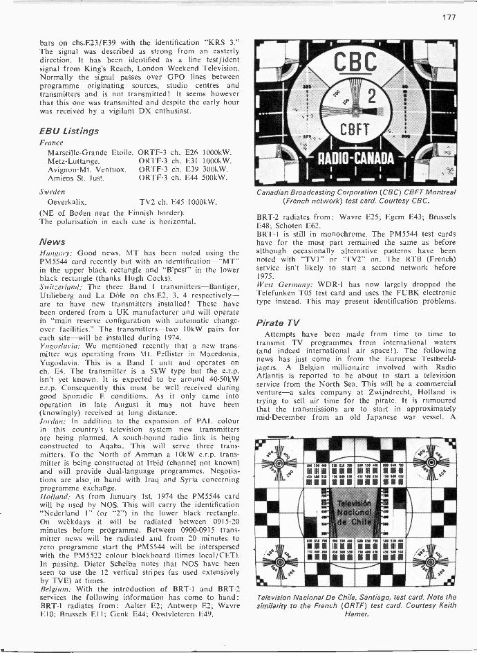
177
bars on chs.E23/E39 with the identification "KRS 3."The signal was described as strong from an easterlydirection. It has been identified as a line test/identsignal from King's Reach, London Weekend Television.Normally the signal passes over GPO lines betweenprogramme originating sources, studio centres andtransmitters and is not transmitted! It seems howeverthat this one was transmitted and despite the early hourwas received by a vigilant DX enthusiast.
EBU ListingsFrance
Marseille -Grande Etoile. ORTF-3Metz-Luttange. ORTF-3Avignon -Mt. Ventuox. ORTF-3Amiens St. Just. ORTF-3
Sweden
Oeverkalix.
ch. E26 1000kW.ch. E31 1000kW.ch. E39 300kW.ch. E44 500kW.
TV2 ch. E45 1000kW.(NE of Boden near the Finnish border).The polarisation in each case is horizontal.
NewsHungary: Good news. MT has been noted using thePM5544 card recently but with an identification-"MT"in the upper black rectangle and "B'pest" in the lowerblack rectangle (thanks Hugh Cocks).Switzerland: The three Band 1 transmitters-Bantiger,Utilieberg and La Dole on chs.E2, 3, 4 respectively-are to have new transmitters installed! These havebeen ordered from a UK manufacturer and will operatein "main reserve configuration with automatic change-over facilities." The transmitters-two 10kW pairs foreach site-will be installed during 1974.Yugoslavia: We mentioned recently that a new trans-mitter was operating from Mt. Pellister in Macedonia,Yugoslavia. This is a Band I unit and operates onch. E4. The transmitter is a 5kW type but the e.r.p.isn't yet known. It is expected to be around 40-50kWe.r.p. Consequently this must be well received duringgood Sporadic E conditions. As it only came intooperation in late August it may not have been(knowingly) received at long distance.Jordan: In addition to the expansion of PAL colourin this country's television system new transmittersare being planned. A south -bound radio link is beingconstructed to Aqaba. This will serve three trans-mitters. To the North of Amman a 10kW e.r.p. trans-mitter is being constructed at Irbid (channel not known)and will provide dual -language programmes. Negotia-tions are also, in hand with Iraq and Syria concerningprogramme exchange.Holland: As from January 1st, 1974 the PM5544 cardwill be used by NOS. This will carry the identification"Nederland 1" (or "2") in the lower black rectangle.On weekdays it will be radiated between 0915-20minutes before programme. Between 0900-0915 trans-mitter news will be radiated and from 20 minutes tozero programme start the PM5544 will be interspersedwith the PM5522 colour blockboard (times local/CET).In passing. Dieter Scheiba notes that NOS have beenseen to use the 12 vertical stripes (as used extensivelyby TVE) at times.Belgium: With the introduction of BRT-1 and BRT-2services the following information has come to hand:BRT-1 radiates from: Aalter E2; Antwerp E2; WavreE10; Brussels El I; Genk E44; Oostvleteren E49.
Canadian Broadcasting Corporation (CBC) CBFT Montreal(French network) test card. Courtesy CBC.
BRT-2 radiates from:E48; Schoten E62.BRT-1 is still in monochrome. The PM5544 test cardshave for the most part remained the same as beforealthough occasionally alternative patterns have beennoted with "TV1" or "TV2" on. The RTB (French)service isn't likely to start a second network before1975.West Germany: WDR-1 has now largely dropped theTelefunken T05 test card and uses the FUBK electronictype instead. This may present identification problems.
Wavre E25; Egem E43; Brussels
Pirate TVAttempts have been made from time to time to
transmit TV programmes from international waters(and indeed international air space!). The followingnews has just come in from the Europese Testbeeld-jagers. A Belgian millionaire involved with RadioAtlantis is reported to be about to start a televisionservice from the North Sea. This will be a commercialventure-a sales company at Zwijndrecht, Holland istrying to sell air time for the pirate. It is rumouredthat the transmissions are to start in approximatelymid -December from an old Japanese war vessel. A
sob 3S0 ON 100 LSO 71111
1111 M M MISO SOB SW 710 WO ISO
gIIMNU IIIIIIII
31
350 100
t11 IIN HI450 SOO SSO
M 11
TelevisionNockmolde Chile
3M 334 MO
W 3M 330
450 100
130 000 ISO
Television Nacional De Chile, Santiago, test card. Note thesimilarity to the French (ORTF) test card. Courtesy Keith
Hamer.

178
radio station is also to be carried aboard this shipwhich cost one million Dutch Guilders. The informa-tion is rather vague at this stage and one cannot besure whether anything will come to fruition. Shouldthe situation develop further and detailed informationcome to hand it will be pased on at once!
Signal LoggingSince October 1st, I have been using a new system of
signal logging. This has been done to simplify the logand save space while at the same tme providing a moreobjective appraisal of the signals received. The systemadopted is a variation of the VAFI one (as used by theWTFDA) but with some additions. An example:28/11 /73-Dull0715 M355 M E3 Denmark 5544 tcThe first line is obvious-date and local weather. Thesecond line gives the local time, signal duration, visionstrength, fading, interference, propagation mode, channel,country of origin and signal content (in this case thePM5544 test card). With repeated signals the letter Rwould appear after "M355." The codes for each sectionare as follows:
Vision Fading InterferenceO No signal 01 Just detectable 12 Heavy snow 23 Moderate snow 34 Light snow 45 Snow free 5
Auroral flutter 0 Loss of signalDeep to fast 1 ExtremeSlow fade 2 HeavyModerate fade 3 ModerateLight 4 LightNone 5 None
Propogation Modes Signal DurationA AuroralE Sporadic EF F2 LayerTE Trans -equatorialT Tropospheric seconds)M Meteor Shower/Scatter R Repeated
Another example:17/11/73-Clear skies0809 M255R ME2 Sweden tc0819 M355R ME2 Norway Fubk tc
I have discontinued the practice of noting local airpressure and temperature since apart from troposphericsignals these have no relevance.
S Short/Burst/PingM Medium (at least 5
seconds)L Long (at least 15
short bursts
From Our Correspondents .A long letter from Clive Athowe (Norwich) describes
reception over the October period in his area. It is amost inspiring log, showing that most types of signalhave arrived in East Anglia (where most signals seemto go!). Apart from tropospheric and MS signals, SpEseems to have been very active during the 17th (withArabic music) -22nd period including Albania. A photo-graph was included of the Albanian clock. This has thenumerals 12, 3, 6 and 9, there being just markings forthe other hours. These are white (with white hands, in-cluding the seconds hand) on a black/dark background.Other points of interest are: an identification for SWF-3Marienberg ch. E44-"S3 STGT3"; and the DFF secondchain has been noted with the test pattern carrying theidentification "DDR-F 2".
To conclude this month we give further details fromthe letter received from D. Minns, Bahrain, ArabianGulf (see also last month).
Damman, Saudi Arabia oh. E8 has a very strong signalinto Bahrain with mainly Arabic programmes but also attimes English programmes with Arabic subtitles orArabic dubbed sound. The test card used is the "IndianHead" but with the Indian Head deleted and crossedswords with a palm tree above inserted. At times a formof grey scale is radiated but with frequency -responsegratings.
A regular long-distance service is received from Kuwaiton chs. E9/E1 1: the virtually permanent tempera-ture inversion layer over the Gulf provides an almostconsistent signal. Reception tends to vary according totemperature and humidity however, fading rather duringthe cooler winter months. The Indian Head card is againused. English programmes are often radiated with dubbedArabic sound.
Doha (Qatar) ch. E9 and Abu Dhabi chs. E5/6 areregularly received with some fading after dark. The latteruses a version of the PM5540 test card. Of some im-portance is the existence of a ch. E2 Iranian transmitterreceived regularly during the mornings-this has alsobeen received in Malta. Dubai transmits in monochromeat the 1.f. end of Band III (colour expected soon).
The receivers used are mostly Japanese, basically forthe 525 -line, 4.5MHz system M but with convertors for5.5MHz system B sound.
That concludes the very interesting letter from D.Minns: we hope his excellent reception will continue.We are always pleased to hear from enthusiasts in distantcountries about reception conditions in their areas.
MILLER'S MISCELLANY-continued from page 175
in both senses of the word. It transpired that havingcompleted wiring in the tuner he'd switched the seton and in a moment of temporary aberration hadtaken hold of the aerial lead in one hand and theset's chassis with the other, thereby receivingthe 450V d.c. straight across his body. Unable to letgo with either hand he'd luckily fallen away from thebench, dragging the set with him. I say luckilybecause this pulled the mains lead out. The miraclewas that the c.r.t. hadn't gone off in his face whenthe set crashed on to him. What was that aboutnostalgia?
Now, Voyeur!In lighter vein, a friend told me recently of a
discovery he made when on a service call to a setfitted with the Thorn 850 chassis. Crouching behindthe set he removed the (v.h.f.) tuner and found thatthe hole in the cabinet afforded a splendid view ofthe mini -skirted owner's anatomy. It would appearthat ever since on each call to the set whether forlow width, lack of sync or whatever removal andcleaning of the tuner has been necessary . . .
We had one, but the wheel came off!I read that a manufacturer now offers a device
"designed to interface with t.t.l. or I.B.M. level buses,enabling high speed mainframes to feed the slowert.t.l. peripheral equipment". It's called a dual busdriver. Does the Transport and General Workers'Union know about this? Seems to me, what withsemiconductors and bus drivers, we could be headingfor a demarcation dispute . . .

179
THE 'TELEVISION' COLOUR RECEIVER
FORTHE purpose of this feature is to co-ordinate theexperiences reported to us by readers who havesuccessfully completed the colour receiver projectstarted in our April 1972 issue and to pass on allinformation likely to be of help to others. Reportsto date indicate that we have already covered in thisfeature (see the November, December and Januaryissues) all the recurrent problems encountered. Wewould nevertheless like to continue to hear fromconstructors of their experiences with the set. Any
Dear Sir,
hints that might save others' time are particularlywelcome. Contributions published in this featurewill be paid for at our normal rates: contributors'addresses will not be divulged. We regret that it isnot possible for us to answer telephone enquiries re-garding this feature or the set itself. The FaultFinding Advisory Service will continue-applicationforms were provided in the August, September andOctober 1973 issues.
TUNER CONTROL UNITSSome of the push-button tuner control units suppliedcontain a fixed resistor in series with the earth con-nection 8D. This is worth noting since the resistorrestricts the tuning range-channels 25 down maynot be obtained. If this situation is experiencedthere is a simple solution-reverse the connections to8C and 8D.
W. C. Clark.
Dear Sir,
VOLUME CONTROLThe range of adjustment provided by the volumecontrol when this is incorporated in the audio feed-back circuit is rather limited. Placing the volumecontrol at the input to the audio module increasesthe range considerably. This can be done as follows.Connect a fixed 3kt2 resistor (value suggested by thei.c. manufacturer, General Electric, New York,USA) in the circuit position originally used for thevolume control (across 9C and 9J). Feed the audiomodule input (9B) from the slider of a log. potentio-meter connected between the i.f. strip audio output(2C) and chassis (9J). The original potentiometerworks all right in this position but the value is notimportant-anything from about 25k11 to 2501(11will do.
R. Windhurst.
Dear Sir,
GREY -SCALE ADJUSTMENTSI am not too enthusiastic about the method yousuggested last month for setting up the c.r.t. back-ground (first anode) controls: setting them all tomaxiumum even briefly results in rather a heftybeam current. Whilst working with the set I have
evolved the following grey -scale tracking procedurewhich has proved entirely satisfactory.
Turn the contrast control to maximum, the bright-ness control half way and the colour (saturation)control to minimum (no colour). Switch off the blueand green guns and adjust the red background con-trol R437 until a picture is just visible. Repeat thisprocedure with the other guns (R435 and R436).Then switch all three guns on, turn up the brightnessand tweak the background controls if necessary forcorrect reproduction of dark grey. Finally adjust thedrive controls R401-3 for best reproduction of fleshtones with normal user control settings.
T. Shanks.
Dear Sir,
LOUDSPEAKER SCREENINGInterference to the picture caused by the loudspeakercan be almost entirely eliminated by adding extrasteel screening around the loudspeaker on the c.r.t.side. A suitable piece of mild steel can be formedinto a U bend and held in place by means of double -sided Sellotape.
E. Davidson.
Dear Sir,
REMOTE CONTROLThe remote channel change circuit I have devisedfor use with the colour receiver has been success-fully tried out and may be of interest to otherconstructors. The circuit of the channel selectionsystem, also the varicap tuner connections, is shownin Fig. 1. There are four stages in the selector cir-cuit (additional stages for further channels couldbe added if required), each stage using a pair oftransistors which together perform the same func-tion as a silicon controlled switch. When the set is

180
R11
100k
0
Aerial inputC6
470p
&--1 IC7
.--11--.470p
R161.5M
From 2FIIN.
AFC
From 26
12V from 6M1
R156.8k
R175 6k
5.4,01\r
ELC 043
20 4. 8. 90 10
R1
AGC from 2K 220
C8005
C21
R141k
C10 C11
°5T T"
Tuningvoltage
C12 101320
i6vT T'005
300V from junctionFS502/R506
IF topre amp
3iR27
0.11
Tuningpotentiometers
Resistors IW unless otherwise indicated
Channel changeswitch on set
1
Remote channelic---change switch
RI47k
R26390Wa
B
4,7
Plug and socketon sub board
B C
C1450
35VZ
250k- 250k 250k 250k
R19R18 47k47 2W
05.0022
V1
XN32
3
4
012TAA550
RI282k
Numicator
30V from 6K
Supply rail.
D3
R4
rl
R6
rr
R81.5k 1 5k 1.5k
01 E13 D7
RIO1'5k
5
0.1
R247k
D2
DI
D4 07
T rl
05
evi
CI2
"Psv
R34.7k
Tr3
C2
0.22Tr2
R54.7k
D9 DII
Tr5
C3
0.22Tr4
R747k
TrT
C4
0.22Tr6
R947k
Tr8
/7717
Fig. 1: Remote control and varicap tuner circuitry used by B.
switched on the voltage on the "supply rail"(junction RI /R2) is 30V. As a result CI chargesvia R2 and DI and eventually sufficient current ispassed by D5 for Tr2 to conduct. Tr I and Tr2 thenlock on, relay A operates, the supply rail voltagedrops to 1 V and Cl discharges via D2. On operatingthe channel change switch-there is one on the setand another at the cable -connected remote unit-C5 momentarily shorts the supply rail to earth as itcharges, Trl cuts off so that Trl and Tr2 release,and the supply rail returns to 30V. Relay A alsoreleases of course. As the collector of Tr2 goespositive a positive voltage appears at Tr4 base sothat Tr4 and Tr3 lock on and relay B operates, thesupply rail falling to I V again. Each subsequentoperation of either channel change switch steps theoperating stage on one until the last stage switchesoff. The supply rail then returns to and stays at 30V,Cl charges as at initial switch on and relay Aoperates once again. R11 discharges C5 betweenswitch operations. If it is found that channel I doesnot automatically appear on first switching on, one
C. James.
116
C16
C19
Further channels if required
Tr1.3,5,7 ZT X503Tr2,4,6,13 ZTX 303
01- 1311 1N4148
Coil tags
jg apart
1(8.0
1/Width
Fig. 2: Outline and dimensions of the relay used for channelselection and numicator switching. The relay is a standard
PO type.
of the other channels coming on instead, an 0.5/4Fcapacitor can be added from Tr2 base to the 30Vline (junction RI/ D3) to ensure that channel 1
always comes on first. One relay contact switchesthe appropriate channel tuning potentiometer intocircuit; the other connects the appropriate numi-cator cathode into circuit to give channel indication.
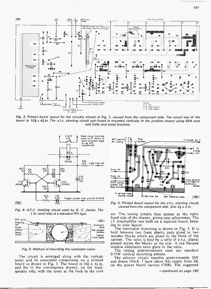
181
F1-233 i20 ABC 141 Nun, starIRFI .ndut 03 00
GS
SO
Varicao tunerELCI003
IC*
"1.
1.
1413
Poe
=de
.300
Numicator cathodes
2 3
Pos.sub
on of AFC shorting circuitoars (mounted vertIcally)
Tuningpotent .orneters
T CI9
RI21 I A le C E Eft SC E OC
RI(Lei t:11
00 BO 00 a Sc, AS 0 oo11
I R27/C21
0I e OF E OF E OF E OF
R.
ICh noel change switch
on cabinet
ID:
14OC E. OC
It 5
c R3 C
1,1 Tr2
C FTr3 Trc
Dt
0-111-
}Rhemoangte channel
1,17
BB
109
0
E ScES: °C811
Oa
COE
1'5 TeeCCO
Ir?
OP
E
RelaysE -F coilA-8 Mike contactC-0 make contact
Fig. 3: Printed board layout for the circuitry shown in Fig. 1, viewed from the component side. The actual size of theboard is 10i x 4* in. The a.f.c. shorting circuit sub -board is mounted vertically in the position shown using 6BA nuts
and bolts and metal brackets.
R201k
Tr92N130
I 823 I
R25lk
L124/5C/E
Reed relay mountedclose to IF circuit toavoid screened leads
AFCtransformer
R28240 +30V from 6K
C206.835V
CI90.22 Trigger pulses from junction R12/C16
2 OV
Fig. 4: A.F.C. shorting circuit used by B. C. James. The1 in. reed relay is a standard PO type.
PVC strip_Dawing
pinFoamplasticWoodblock
I 824 I
Numicatorvalve
'I Red Pwinerspex
/ Cabinetpanel
Fig. 5: Method of mounting the numicator valve.
The circuit is arranged along with the varicaptuner and its associated components on a printedboard as shown in Fig. 3. The board is IN x 41 in.and fits in the convergence drawer, on the loud-speaker side, with the tuner at the back in the cool
AFC 'switchfor tuning
From 2F
From 2Ge.
From tuningpresets (viarelay contacts
To varicap tuner(tuning volts)
PlugSockets
Cll/tuner pin 5
r10
R20C
Tr9
24
18
R22
125
Torelaycoil
From 1212/C16
(fornicatoranode)
+30V from 6K 661.5 mounting holes I 826
Fig. 6: Printed board layout for the a.f.c. shorting circuit,viewed from the component side. Size 2i x 2 in.
air. The tuning presets then appear at the right-hand side of the drawer, giving easy adjustment. Thei.f. preamplifier was built on a separate board, keep-ing to your layout.
The numicator mounting is shown in Fig. 5. It isheld between two foam plastic pads glued to twowooden blocks which are glued to the front of thecabinet. The valve is held by a strip of p.v.c. plasticpinned across the blocks at the rear. A red Perspexwindow eliminates neon glare in the valve.
The tuning potentiometers used are standard0.15W vertical mounting presets.
The selector circuit requires approximately 30Vand draws 15mA. I have taken this supply from 6Kon the power board (across C508). The suggested
-continued on page 183

182
0\10. 10151k%G.R.WILDING
Intermittent Line OutputThe fault on a Pye single -standard colour receiverwas intermittent line output due to an intermittentfault in the PCF802 line oscillator circuit. A newPCF802 failed to cure the trouble and on checkingtheir front -to -back resistance both discriminatordiodes in the flywheel sync circuit were found to beOK. We next made a close but fruitless inspectionfor dry -joints, then decided to change the threeelectrolytics used. The intermittency persisted how-ever. It is our experience that capacitors rather thanresistors are the most common causes of intermittentoscillation so we decided to continue replacing them.The culprit turned out to be the 320pF feedbackcapacitor from the oscillator tuned circuit to thepentode control grid. On replacing this we found itnecessary to reposition the oscillator coil core whichforms the preset line hold control. The drill as usualwith this type of circuit is to place the main holdcontrol midway then adjust the preset for optimumpicture lock.
Open -circuit Heater ChainA tip worth remembering is that if a slight high-pitched note can be heard from a receiver with anopen -circuit heater chain you will find that thenormal causes of this condition-open-circuit fuses,switch contacts or dropper resistor sections-are notto blame. The cause is an open -circuit valve or c.r.t.heater: the resulting high -voltage strain across theheater -cathode insulation of the boost rectifier-which is usually the first valve in the chain-oftenresults in it producing this high-pitched vibration.Whenever a break exists in the heater chain belowthe supply point from the thermistor or dropperresistor the set should be disconnected from thesupply immediately to preyent damaging the heater -cathode insulation of the valves above the break.
Low Boost/LT SuppliesThe complaint reported on a Bush Model TV166Uwas "set working on v.h.f. only." This naturally gavethe impression that the u.h.f. tuner or the systemswitch was at fault. On switching on however itbecame apparent that this was not the case, for whilethere was a lockable picture on 405 lines togetherwith sound the raster was only about half the normal
height-the width was near normal. On switchingto 625 the height decreased still further, the rasterbecame blank and noise -free and there was no sound.
In these models the 22V supply for the transistori.f. stages and the u.h.f./v.h.f. tuner assembly is ob-tained from a low -voltage winding on the line outputtransformer. As all symptoms had developed sim-ultaneously it appeared that the line output stagewas at fault, the height being reduced due to lowboost voltage while the reduced l.t. supply was in-sufficient to enable the u.h.f. oscillator to operate.The disturbing feature was the near normal width,since a drastic reduction in the boost and l.t. railvoltages would if caused by a low -emission line out-put valve or high -resistance feed resistor in the widthcircuit be accompanied by a comparable widthreduction.
A heavy leak across the boost rail and chassiswould reduce the boost voltage and by loading theoutput transformer reduce the 22V supply. A heavyleak across the 1.t. supply would have a similareffect. Voltage tests confirmed that both the boostand the 1.t. voltages were low, the former 400Vinstead of 780V and the latter about 12V. Althoughlittle hope was held out the line timebase valves werechanged since all simple possibles must be tried firstwhen tackling a difficult fault. We have on occasionscome across a line oscillator which is able to providenear normal line width but as a result of the end ofits switching pulse output being rounded the lineoutput pentode is not cut off as cleanly as it shouldbe, resulting in reduced flyback voltages and boostrail potential.
The capacitors in the output stage associatedwith the boost voltage were next checked or re-placed, then the line output valve anode d.c. feedcoil checked by substitution. As the trouble persistedwe next considered the possibility that there was ac.r.t. first anode leak-such a leak sometimesdevelops, imposing a sufficiently high load to reducethe height to well below normal even with the heightcontrol at maximum. Removing the first anodesupply to the tube base failed to produce any notice-able improvement in the boost voltage however andas there was no heavy leak across the l.t. circuit wewere left with the conclusion that the line outputtransformer was faulty. A replacement restorednormal results on both systems. It is always bestwhen confronted with the possibility of a faulty lineoutput transformer to eliminate all other likelihoodsfirst.
No Results: Pye 368 ChassisNo results on a model fitted with the Pye 368 chassiswas due to the mains fuse F1 being blown. Our firstmove after replacing the fuse was naturally to checkthat no short existed across the mains plug con-nections. The low resistance reading obtained withthe test prods either way suggested that the h.t.rectifier might have developed a short as a result ofwhich pure a.c. was being applied to the electrolyticscausing one or more to break down. There is how-ever a complication which must be taken intoaccount on this chassis. System changeover is effectedby a microswitch linked to the tuner: when this isoperated mains a.c. is applied via a fuse and low -value resistor (R69, Fig. 1) to one or other of a pairof solenoids L22/L23. The energised solenoid thenpulls the system switch in the appropriate direction.
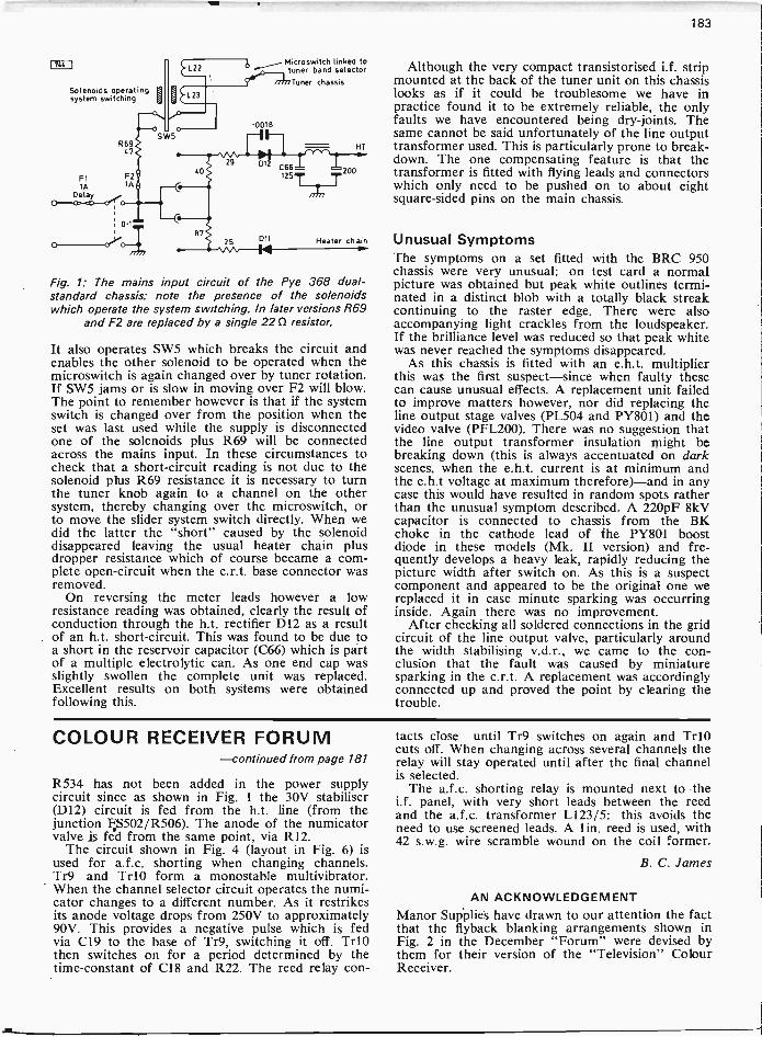
183
47
F2IA
EMI
Solenoids operatingsystem switching
R69
FlIA
0=Lei.
0.1.
0 c"Vo-ki/7777
87
Microswitch linked totuner band selectorTuner chassis
29 012 066
1257
25 Dli
HT
200
Heater chain
Fig. 1: The mains input circuit of the Pye 368 dual -standard chassis: note the presence of the solenoidswhich operate the system switching. In later versions R69
and F2 are replaced by a single 220 resistor.
It also operates SW5 which breaks the circuit andenables the other solenoid to be operated when themicroswitch is again changed over by tuner rotation.If SW5 jams or is slow in moving over F2 will blow.The point to remember however is that if the systemswitch is changed over from the position when theset was last used while the supply is disconnectedone of the solenoids plus R69 will be connectedacross the mains input. In these circumstances tocheck that a short-circuit reading is not due to thesolenoid plus R69 resistance it is necessary to turnthe tuner knob again to a channel on the othersystem, thereby changing over the microswitch, orto move the slider system switch directly. When wedid the latter the "short" caused by the solenoiddisappeared leaving the usual heater chain plusdropper resistance which of course became a com-plete open -circuit when the c.r.t. base connector wasremoved.
On reversing the meter leads however a lowresistance reading was obtained, clearly the result ofconduction through the h.t. rectifier D12 as a resultof an h.t. short-circuit. This was found to be due toa short in the reservoir capacitor (C66) which is partof a multiple electrolytic can. As one end cap wasslightly swollen the complete unit was replaced.Excellent results on both systems were obtainedfollowing this.
Although the very compact transistorised i.f. stripmounted at the back of the tuner unit on this chassislooks as if it could be troublesome we have inpractice found it to be extremely reliable, the onlyfaults we have encountered being dry -joints. Thesame cannot be said unfortunately of the line outputtransformer used. This is particularly prone to break-down. The one compensating feature is that thetransformer is fitted with flying leads and connectorswhich only need to be pushed on to about eightsquare -sided pins on the main chassis.
Unusual SymptomsThe symptoms on a set fitted with the BRC 950chassis were very unusual: on test card a normalpicture was obtained but peak white outlines termi-nated in a distinct blob with a totally black streakcontinuing to the raster edge. There were alsoaccompanying light crackles from the loudspeaker.If the brilliance level was reduced so that peak whitewas never reached the symptoms disappeared.
As this chassis is fitted with an e.h.t. multiplierthis was the first suspect-since when faulty thesecan cause unusual effects. A replacement unit failedto improve matters however, nor did replacing theline output stage valves (PL504 and PY801) and thevideo valve (PFL200). There was no suggestion thatthe line output transformer insulation might bebreaking down (this is always accentuated on darkscenes, when the e.h.t. current is at minimum andthe e.h.t voltage at maximum therefore)-and in anycase this would have resulted in random spots ratherthan the unusual symptom described. A 220pF 8kVcapacitor is connected to chassis from the BKchoke in the cathode lead of the PY801 boostdiode in these models (Mk. II version) and fre-quently develops a heavy leak, rapidly reducing thepicture width after switch on. As this is a suspectcomponent and appeared to be the original one wereplaced it in case minute sparking was occurringinside. Again there was no improvement.
After checking all soldered connections in the gridcircuit of the line output valve, particularly aroundthe width stabilising v.d.r., we came to the con-clusion that the fault was caused by miniaturesparking in the c.r.t. A replacement was accordinglyconnected up and proved the point by clearing thetrouble.
COLOUR RECEIVER FORUM-continued from page 181
R534 has not been added in the power supplycircuit since as shown in Fig. 1 the 30V stabiliser(D12) circuit is fed from the h.t. line (from thejunction FS502/R506). The anode of the numicatorvalve is fed from the same point, via R12.
The circuit shown in Fig. 4 (layout in Fig. 6) isused for a.f.c. shorting when changing channels.Tr9 and Tr10 form a monostable multivibrator.When the channel selector circuit operates the numi-cator changes to a different number. As it restrikesits anode voltage drops from 250V to approximately90V. This provides a negative pulse which is fedvia C19 to the base of Tr9, switching it off. Tr10then switches on for a period determined by thetime -constant of C18 and R22. The reed relay con-
tacts close until Tr9 switches on again and Tr10cuts off. When changing across several channels therelay will stay operated until after the final channelis selected.
The a.f.c. shorting relay is mounted next to thei.f. panel, with very short leads between the reedand the a.f.c. transformer L123/5: this avoids theneed to use screened leads. A 1 in. reed is used, with42 s.w.g. wire scramble wound on the coil former.
B. C. James
AN ACKNOWLEDGEMENTManor Supplies have drawn to our attention the factthat the flyback blanking arrangements shown inFig. 2 in the December "Forum" were devised bythem for their version of the "Television" ColourReceiver.

184
YOURPROBLEMS
FERGUSON 3646The problem with this set is that the 220pF 8kVcapacitor C114 from the boost diode cathode tochassis keeps burning out. This occurs when the setis switched to u.h.f., and happens about every threeweeks. The boost diode and line output transformerhave been replaced but the fault persists.-J. Garner(Portsmouth).
You are not alone in having trouble with thiscapacitor and the fact that it breaks down frequentlydoes not usually indicate that there is a fault condi-tion, though spark overs in the PL500 line outputvalve do not help. We suggest you obtain a differenttype and wire it as far as possible from the PL500which operates at a high temperature-even smalltemperature rises have a drastic effect on capacitorand insulation resistances. It is unfortunate thereforethat C114 is situated in a warm spot. We take itthat the width control is not over advanced so thatthe PL500 is over -run, and that it operates normally.If not, check R141 (l8M12) and R140 (2.2MQ) whichare in series with its slider. It could help to replacethe pulse feedback capacitor C113 (100pF) to thewidth circuit. Make sure that all dropper and smooth-ing resistors are of the correct value so that the h.t.line is at the correct voltage. Also check that thePL500 screen feed resistor R138 (.22kn) is withintolerance. (BRC 1400 chassis.)
DEFIANT 9A52The problem is complete lack of v.h.f. signal and Iassociate this with the large negative signal at theanode of the a.g.c. valve (PCL84 triode section). ThePCL84 pentode section cathode voltage also seemshigh on v.h.f., at about 12V. The contrast is non-existent, the contrast control having no effect at all.Extensive component checks in the a.g.c. circuit havefailed to put matters right. The v.h.f. sound andvision can be restored however by earthing the a.g.c.triode anode to chassis. The picture then has exces-sive contrast, the contrast control no effect and thereis a tendency to pulling on whites.-I. Ball (Acton).
The pentode cathode voltage is certainly much toohigh. It should be about 5V on v.h.f. This suggeststhat the fault is basically due to incorrect biasing inthis section of the PCL84. On v.h.f. a bias stabilisingnetwork (10V2 plus 8.2ki2) is switched between the
SOLVED* Requests for advice in dealing with servicing
problems must be accompanied by an lippostal order (made out to IPC Magazines Ltd.),the query coupon from page 185 and a stamped,addressed envelope. We can deal with only onequery at a time. We regret that we cannot supplyservice sheets or answer queries over the telephone.We cannot provide modifications to circuitspublished nor comment on alternative ways ofusing them.
screen grid and cathode of this stage: these resistorstend to change value-they should be not less than18ki2 in total. Also check the value of the cathoderesistor R122 (22012). In the a.g.c. circuit it is worthchecking the triode's grid return resistor (R127,100ki2), the 10M resistor (R132) in series with thecontrast control slider and the 681d2 resistor (R125)to chassis from the earthy end of the contrast con-trol. An extra 100ki2 resistor in parallel with R127may help. (Early Plessey dual -standard chassis.)
KB SV149The fault with this set is that the picture rolls andcannot be locked by operating the field hold control.Setting the field hold control to its limit results in thepicture rolling slowly but still without lock.-T.Minor (Salford).
We would have thought that a new PCL805 fieldtimebase valve would cure the trouble. If not thefault seems to be loss of lock because the field holdcontrol can't reach it rather than lack of sync. CheckR86 and R82 which are in series with each end ofthe hold control therefore, also C75 which is acrossthe whole network (PCL805 triode section grid/cathode circuit). If one of the cross -coupling capa-citors C73, C74 or C78 is faulty the hold positioncould be shifted out of the range of the control.Make sure that the PCL805 pentode section cathodedecounling electrolytic C82 is in order, especially ifthere is any tendency to cramping at the bottom ofthe picture, by temporarily connecting a substitute inparallel with it. (ITT/KB VC200 chassis.)
ULTRA V1770I wish to replace the vision detector and a.g.c. clampdiodes in this set but the types originally fitted appearto be obsolete.-L. Watson (Egham).
We suggest the use of an 0A70 or 0A90 as thevision detector and a general purpose silicon diodesuch as the BA148 as the clamp.
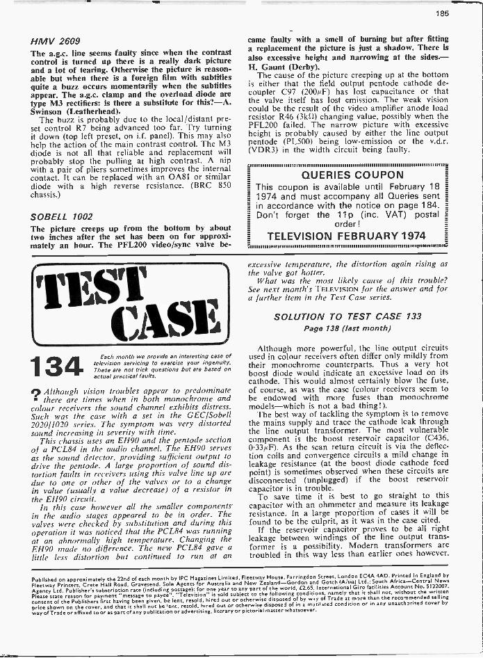
185
HMV 2609The a.g.c. line seems faulty since when the contrastcontrol is turned up there is a really dark pictureand a lot of tearing. Otherwise the picture is reason-able but when there is a foreign film with subtitlesquite a buzz occurs momentarily when the subtitlesappear. The a.g.c. clamp and the overload diode aretype M3 rectifiers: is there a substitute for this?-A.Swinson (Leatherhead).
The buzz is probably due to the local/distant pre-set control R7 being advanced too far. Try turningit down (top left preset, on i.f. panel). This may alsohelp the action of the main contrast control. The M3diode is not all that reliable and replacement willprobably stop the pulling at high contrast. A nipwith a pair of pliers sometimes improves the internalcontact. It can be replaced with an 0A81 or similardiode with a high reverse resistance. (BRC 850chassis.)
SOBELL 1002The picture creeps up from the bottom by abouttwo inches after the set has been on for approxi-mately an hour. The PFL200 video/sync valve be-
came faulty with a smell of burning but after fittinga replacement the picture is just a shadow. There isalso excessive height and narrowing at the sides.-H. Gaunt (Derby).
The cause of the picture creeping up at the bottomis either that the field output pentode cathode de -coupler C97 (200/4F) has lost capacitance or thatthe valve itself has lost emission. The weak visioncould be the result of the video amplifier anode loadresistor R46 (3k1) changing value, possibly when thePFL200 failed. The narrow picture with excessiveheight is probably caused by either the line outputpentode (PL500) being low -emission or the v.d.r.(VDR3) in the width circuit being faulty.
QUERIES COUPONThis coupon is available until February 181974 and must accompany all Queries sentin accordance with the notice on page 184.Don't forget the 11 p (inc. VAT) postal
order !
TELEVISION FEBRUARY 1974
r174SvrCASE]
134 Each month we provide an interesting case oftelevision servicing to exercise your ingenuity.These are not trick questions but are based onactual practical faults.
Although vision troubles appear to predominate there are times when in both monochrome and
colour receivers the sound channel exhibits distress.Such was the case with a set in the GEC/Sobell2020/1020 series. The symptom was very distortedsound increasing in severity with time.
This chassis uses an EH90 and the pentode sectionof a PCL84 in the audio channel. The E1190 servesas the sound detector, providing sufficient output todrive the pentode. A large proportion of sound dis-tortion faults in receivers using this valve line up aredue to one or other of the valves or to a changein value (usually a value decrease) of a resistor inthe EH90 circuit.
In this case however all the smaller componentsin the audio stages appeared to be in order. Thevalves were checked by substitution and during thisoperation it was noticed that the PCL84 was runningat an abnormally high temperature. Changing theEH90 made no difference. The new PCL84 gave alittle less distortion but continued to run at an
excessive temperature, the distortion again rising asthe valve got hotter.
What was the most likely cause of this trouble?See next month's TELEVISION for the answer and fora further item in the Test Case series.
SOLUTION TO TEST CASE 133Page 138 (last month)
Although more powerful, the line output circuitsused in colour receivers often differ only mildly fromtheir monochrome counterparts. Thus a very hotboost diode would indicate an excessive load on itscathode. This would almost certainly blow the fuse,of course, as was the case (colour receivers seem tobe endowed with more fuses than monochromemodels-which is not a bad thing!).
The best way of tackling the symptom is to removethe mains supply and trace the cathode leak throughthe line output transformer. The most vulnerablecomponent is the boost reservoir capacitor (C436,0.33µF). As the scan return circuit is via the deflec-tion coils and convergence circuits a mild change inleakage resistance (at the boost diode cathode feedpoint) is sometimes observed when these circuits aredisconnected (unplugged) if the boost reservoircapacitor is in trouble.
To save time it is best to go straight to thiscapacitor with an ohmmeter and measure its leakageresistance. In a large proportion of cases it will befound to be the culprit, as it was in the case cited.
If the reservoir capacitor proves to be all rightleakage between windings of the line output trans-former is a possibility. Modern transformers aretroubled in this way less than earlier ones however.
Published on approximately the 22nd of each month by IPC Magazines Limited, Fleetway House,Farringdon Street, London EC4A 4AD. Printed in England byFleetway Printers, Crete Hall Road, Gravesend. Sole Agents for Australia and New Zealand-Gordon and Gotch (A/sia) Ltd.: South Africa-Central NewsAgency Ltd. Publisher's subscription rate (including postage): for one year to any part of the world, £2.65. International Giro facilities Account No. 5122007.Please state reason for payment "message to payee". "Television" is sold subject to the following conditions, namely that it shall not, without the writtenconsent of the Publishers first having been given, be lent, resold. hired out orotherwise disposed of by way of Trade at more than the recommended sellingprice shown on the cover, and that it shall not be lent, resold, hired out or otherwise disposed of in a mutilated condition or in any unauthorised cover byway of Trade or affixed to or as part cf any publication or advertising, literary or pictorial matter whatsoever.

186
TELEVISION CLASSIFIED ADVERTISEMENTSThe pre -paid rate for classified advertisements is 6p a word (minimum 12 words), box number 20p extra.Semi -display setting £3.50 per single column inch. All cheques, postal orders, etc., to be made payable toTELEVISION and crossed "Lloyds Bank Ltd." Treasury notes should always be sent registered post.Advertisements, together with remittance, should be sent to the Classified Advertisement Manager, TELE-VISION IPC Magazines Ltd., Fleetway House, Farringdon Street, London, EC4A 4AD, for insertion inthe next available issue.
SERVICE SHEETS: SERVICE SHEETS MANUALS BOOKS SERVICE SHEETS 40p plus S.A.E. * SERVICE SHEET CATALOGUE 25p OVER 12,000 SERVICE SHEETS 8. MANUALS IN STOCK ON COLOUR/MONO... RADIOS, RADIOGRAMS, T/RECORDERS, R/PLAYeRS, ETC. S.A.E. WITH ENQUIRIES 0 NEW BOOKS 8, PUBLICATIONS PRICE 0O NEWNES COLOUR TELEVISION SERVICING MANUAL Vol.1. by G.J.King. 240 pp £4.90
MAZDA BOOK OF PAL RECEIVER SERVICING by D.J.Seal. 288 pp. Illustrated £3.80 diAi...COLOUR TELEVISION SERVICING by G.J.King. 332 pp. Illustrated £4.40
COLOUR TELEVISION by P.S.Carnt. Vol.1. NTSC system principles. 502 pp £5.003.75 111.;
O COLOUR TELEVISION by P.S.Carnt. Vol.2. SECAM systems. 276 pp £3.75 QUESTIONS & ANSWERS ON COLOUR TELEVISION by J.A.Reddihough. 108 pp £0.75 0
BEGINNERS GUIDE TO TELEVISION by G.J.King. 5th Edition. 212 pp £1.60 da BEGINNERS GUIDE TO COLOUR TELEVISION by G.J.King. 2nd Edition. 208 pp £1.95 `X COLOUR TELEVISION PICTURE FAULTS by K.J.Bohlman. Illustrated in colour £2.50 irda Colour Television with Particular Reference to the PAL System by G.N.Patchett £3.00 `. PAL -D COLOUR RECEIVER: Questions & Answers by K.J.Bohlman. 89 pp £0.68
COLOUR RECEIVER TECHNIQUES by T.D.Towers. 88 pp. 79 Illustrations £1.75 COLOUR TELEVISION THEORY by G.H.Hutson. Covers PAL -System. 334 pp
E Principles of PAL Colour Television & Related Systems by H.V.Sims. 162 pp £2.0023..5805 WTELEVISION EXPLAINED by E.A.Spreadbury. Vol.1. Television FundamentalsTELEVISION EXPLAINED by E.A.Spreadbury. Vol.2. PAL Colour System. 116 pp £1.50
1111
TELEVISION SERVICING HANDBOOK by G.J.King. 3rd Edition. 358 pp. 223 Illus £3.80 DICTIONARY OF RADIO & TELEVISION by W.E.Pannett. MICE. 380 pp £1.80 TELEVISION ENGINEERS POCKET BOOK by P.J.McGoldrick. 6th Edition. 400 pp £2.50 0
TV TECHNICIANS BENCH MANUAL by G.R.Wilding. 187 pp. 127 Illustrations £2.50 FM RADIO SERVICING HANDBOOK by G.J.King. 2nd Edition. 206 pp £3.00 RADIO& AUDIO SERVICING HANDBOOK by G.J.King. 2nd Edition. 284 pp £3.00 W Radio Television and Audio Test Instruments by G.J.King. 2nd Edition. 208 pp £3.80
Sound with Vision: Sound Techniques for Television & Film by Alkin. 290 ppift£6.00,..""'TV FAULT FINDING BOOK by Data Publications Ltd. 405/625 Edition. 124 pp £0.50
NEWNES RADIO & TELEVISION SERVICING books bought and sold (all years) Good prices paid W*Please add 10% for Postage and Packing on all books. Send large S.A.E. I -or FREE booklists.: BELL'S TELEVISION SERVICESI 190. KINGS ROAD. HARROGATE, YORKSHIRE. Telephone 0423 - 55885 :e6..
A.L.S. Service Sheet Service10 Dryden Chambers, 119 Oxford Street, London W1R 1PA
Mail Order Onlyi
BooksAlkaitfikAR*S2*
Our stocks now exceed 20,0 0 0 ItemsService Sheet service only 40p Plus SAE. Manuals
ga,,A.,33z,g4t*la
We are pleased toable to offer a
large andinteresting choiseof Books on allelectronic subjects
"Comprehensive Colour TVManual` By J. Mc CourtCOVERS FAULTS CAUSES ON MOST BRITISH SETS
Now only £2 Plus 25p Post & Packing`Comprehensive Black & WhiteTelevision Manual
Most colourT Vs requireverya manual tocover the
amounttlnelfOrMat -
Radio & TelevisionServicing Books
ALSO BY McCOURT
IN 2 VOLUMES Price £5 Post Paid.ion necessaryWe can supply
brought and sold *Beginner§ Guide to Colour manuals forComplete Listsof Service Sheets,
Television" BY G, J. KING,POSTRECOMMENDED FROM OUR BOOK LIST 12-20 e
most makes.S.A.E. for a
Books&
Boards etcPrinted
Plus Free Fault .Finding Charts okNeWSleCter200W
Guide`A to Television Alignment UsingOnly Transmitted Test Signals"BY BR EPTON PRICE 30P PLUS S A EJUST ONE OF OWN UNIQUE BOOKLETS WHICH AREPROVING VERY POPULAR
prompt quoteCuit
price anddelivery
Please supply one Service Sheet, for which my chequP.0.40p &&A.E. enclosed.
NAME - - - - - - - - - - - PLEASE USE BLOCK CAPITALS
ADDRESS
Model Number MAKE TV, Radio etc
LARGE SUPPLIEROF
SERVICE SHEETSAll at 40p each
(T.V., RADIO. TAPE RECORDERS,RECORD PLAYERS, TRANSISTORS,
STEREOGRAMS, RADIOGRAMS,CAR RADIOS)
"PLEASE ENCLOSE LARGE S.A.E.WITH ALL ENQUIRIES & ORDERS"
Otherwise cannot be attended to(Uncrossed P.O.'s please, original
returned if service sheets not available.)
PLEASE NOTEWe operate a "by return of post" service. Anyclaims for non -delivery should be made within7 -days of posting your order.
C. CARANNA71 BEAUFORT PARK
LONDON, N.W.11We have the largest supplies of ServiceSheets (strictly by return of post). Pleasestate make and model number alternative.Free T.V. fault tracing chart or T.V. list on
request with order.Mail order or phone 01-458 4882
SERVICE SHEETS(1925-1974) for Radios, Televisions,Transistors. Radiograms, Car Radios,Tape Recorders, Record Players, etc.
withFREE FAULT FINDING GUIDE
PRICES FROM 5pOver 10,000 models available.
Catalogue 15p + SAEPlease send stamped addressed envelope
with all orders and enquiries.
Hamilton Radio47 Bohemia Road, St. Leonards,
Sussex. Telephone Hastings 29066.
SERVICE SHEETS, Radio, TV etc. 8,000models. Catalogue 15p. S.A.E. enquiries.Telray, 11 Maudland Bank, Preston.
AERIALS
BAINES for High Frequency AerialsFull range of J Beam Aerials
Parabeam UHF PBM 12 E3.35, PBM 18 L4.30Multibeams UHF MBM 30 L4.40, MBM 46L6.90, MBM 70 LI2.10, 2MBM 70 L28.40Stereobeams VHF/FM SBM 2 L2.95, SBM 3L4.40, SBM 4 L4.80, SBM 6 L7.25, PM 3 L2.20.Rotators L32.00, .1B 75/300 L1.60.Accessories: SAE please. Co -Ax lop
I I Dale Cres, Tupton, Chesterfield 542 6DRTel. 863755

187
GENUINE FULL SIZE18 element TV aerialas used by leadingTV companies
ITV.BBct
snrwIli C0101.,Guaranteed
Perfect Pictures.Sere (Cs. We supple
this geom. U M F.aerial for only (2.20.can
be fitted outside or onside(hardy made technicelly
advanced design. Precisiongrid reflector eliminates ghosting
Complete with clamp. instructionsadvice Money lock Reload.
WaICC Bracket 2Sp low LossCable 10p per yard Plug lop di FREEwith Ogee, maps 8 channel referenceof all Radio P. TV TransmittersII550 ocean' TO Pe, PTIO
318 Mansfield M. flifttingheni.
IMPERIAL TRALDING,fusaisITTIL
WRIGHT'S AERIALSUHF/625: Antiference TCIO £3.00; TO 8£4.20. 3 Beam high gain: MBM30 £3.80;MBM46 £5.50; MBM70 £11.00. Please statech. group or transmitter if known.FM stereo: Antiference Mushkillers, Aerialite,or Stereobeam: 2 element £3.20; 4 element£5.55; 6 element £7.80. 300/75 ohm matchingtransformer (Antiference) £1.45.Accessories: 3R alloy masts 55p; chimneylashing kits (1" -If" mast) £1.10; clamps 50p;low loss coax 9p/yd.; coax plugs 9p. S.A.E.for list, or phone for quote.Problem jobs: Send details with order for freeadvice.Post & packing: Aerials 50p, other items 30p.Please add 10% VAT. S.A.E. for lists.
WRIGHT'S AERIALS25 Middlegate, Scawtborpe, Doncaster, Yorks.
Phone (0302) 3080.
WANTED
NEW BVA valves of popular types, PCL805,PY800/l, PL504, etc. Cash waiting. Bearman,6 Potters Road, New Barnet. 449/1934-5.
SERVICE SHEETS purchased. HAMIL-TON RADIO, 47 Bohemia Road, St. Leo -nerds, Sussex.
TOP PRICES PAID for NEWVALVES and TRANSISTORSpopular T.V. and Radio types
KENSINGTON SUPPLIES (A)367 Kensington Street, Bradford 8,
Yorkshire.
TELEVISION, October 1972 issue, urgent.Also details colour tele. reasonable tube, fairlycomplete, price £20-£30. G8EZN, HarfordHouse, Stogursey, Bridgwater, Somerset.
B.R.C. 3000 Chassis and Loom required also19" Cabinet. Phone Braintree 2307. "Marlbern",London Road, Black Notley, Braintree.
FOR SALE
TELEVISION Colour project. Complete 22"receiver. Super Cabinet. Needs Setting up.Best Offer. Details Box 112.
22" BUSH COLOUR, built from makersboards, low hours but frame circuit & IF faults.£60. Phone Hatfield Heath 485.
BOOKS AND PUBLICATIONS
DX -TVThe illustrated booklet, "Long Distance
Television" by Roger W. Bunney is nowavailable, covering all aspects of theDX -TV hobby. Contents include: World-wide channel allocation charts, signalpropagation, receiver requirements withbasic modification details, aerials andpreamplifiers, "off -screen" photography,station identification, test cards, etc.
The publication, costing 55p (includingsurface postage world-wide) is availablefrom:
WESTON PUBLISHING33 Cherville Street, Romsey,
Hants S05 8FB
Direct from manufacturer -a compre-hensive catalogue of UHF & VHF/FMaerials, fixing brackets, chimney lashings,clamps, masts, amplifiers, cable, etc., for theD.I.Y. enthusiast. Complete with usefulinstallation hints. Send 3d. stamp toCLAYDEW ENTERPRISES (T), 261Hardess Street, London, S.E.24.
WORLD RADIO TV HANDBOOK 1974,details of virtually all stations, £3.15 inclusive.David McGarva, PO Box 114, EdinburghEHI 1HP.
LADDERS
LADDERS 'Special Offer' 9' 7" closed -24' 7'extended. Unvarnished timber. £18.70 de-livered. Home Sales Ladder Centre (PTT2),Haldane (North) Halesfield (I) Telford, Shrop-shire. Tel: 0952 586644.
SETS & COMPONENTS
Top 20 Plus Tested TV ValvesPL504 18p PCL84 10pPCF801 15p PCL82 10p30L15 15p PFL200 10pPL36 15p ECC82 10pPCL805/85 15p EH90 10p30FL1/2 15p EY86 15p
Colour Valves Fully TestedPL509 40p PY500/A 30pPL508 30p
Many others available includingMazda Types.
P. & P. 4p per valve, over 12 2Ip per valve,orders over £4 post free.
Prompt service.S.A.E. for free listMail order only.
L. & D. COMPONENTS LTD.,71 Westbury Ave., London N22 6SA.
Tel. 01-888 2701.
EX -RENTALSALL SETS complete with UHF Tuners,many working: -
19" BBC2 Sets at £323" BBC2 Sets at £7
Working Sets to Order.All Sets Re -polished Calls Only.
TV DISPOSALSTel: Bristol 626374
250 -New Resistors well assorted 1-2 watts.Carbon -Hi -Stab Oxide etc. £1.00 Post Free.Whitsam Electrical, 33 Drayton Green Road,London W.13.
DESOLDERWICK-SOLDER-ABSORBING WICK
Approx. tcm, completely desolders a P.C.B.joint. Use with any 20-40w soldering iron.30cm Pack 260 inc. p.p. etc. Multipack. Fourlengths of wick In various widths. 80p Inc.
P.P. RTC.
ORIENTATION LTD, Coverack, Cornwall
MAINS DROPPERS.37-31-97-26-168 0 50p.25-35-97-59-30 0 50p.14-26-97-160 0 50p.14-26-97-173 0 50p.15-19-20-70-63-28-63 o 50p.Post free. C.W.O.Durham Supplies, 367 Kensington Street,Bradford, 8, Yorkshire.
VALVE LISTALL VALVES
FULLY TESTED
One valve postage 3p. Over 5 valvespostage paid.
DY86-97 1211/ PCFRO 5p 6F23 15pEB91 15p PCF86 159 6/30L2 139ECM lOp PCF805 25p 30F5 10pECC95 20o PCL82 121p 30FLI 20pECL80 'no PCL93 12to 30PLI 20oEF80 71p P01,84 1210 30PL13 171pEF183 lOp PCL85 20o MANY MOREEF184 10o PC1.86 171p AVAILABLEEH90 15p PFL200 2.59 S. & W.PC86 20o P1.36 20p ELECTRONICSPC811 20o PL504 20p 114 Bonds)PC900 10o P Y800 121P RoadPCC84 5p PY801 25p RawtenetallPCC189 71p U191 171p RossendalePCC805 15p LT26 lOp Linea.
EX RENTALTV's BARGAIN
23" & 19" 3 Channel with U.H.F. Tuner£3.50
from £50.00from £2
19" & 25' Colour19" & 23" tubes guaranteed
All sets complete.
EDWARDS & SONS103 Goldhawk Road, London W.12
Telephone 743-6996CALLERS ONLY
COLOUR -COLOUR -COLOUR19" DECCA £90.0025" DECCA £100.0025" RBM /PHILIPS £110.0025" THORN £115.0022" DECCA& PHILIPS single standard £130.00Fully serviced, one month's guarantee. Deliveryand Terms can be arranged. Non -workersavailable. S.A.E. Details please.
T.E.S.T.P.O. Box 1. Kirkham, Preston, PR4 2RS
Telephone 077-48 2796 any time.
Components Galore. Pack of 500 mixedcomponents, manufacturers' surplus plusonce used. Pack includes resistors, carbonand W.W., capacitors various, transistors,diodes, trimmers, potentiometers etc. Send£1 + 10p P. & P. C.W.O. To: CaledonianComponents, Strathore Road, Thornton,Fife.
B.R.C. 3000 Power Panels. LTB. Panelsworking £10.50 each p.p. Most B.R.C. Sparesstocked. Panels repaired promptly. New ValvesPL509 £20. All types cheaper. 3. Baker, 1 OldShoreham Road, Southwick, Sussex.
188
VALVES, VALVES. Large stock 1930 to 1973.S.A.E. for quotation. No lists. Also Styli.Quote number of styli or cartridge. Cox Radio,The Parade, East Wittering, Sussex.
EDUCATIONAL
TELEVISIONTRAINING
16 MONTHS' full-time practical andtheoretical training course in Radio &TV Servicing (Mono & Colour) forbeginners.
13 WEEKS' full-time Colour TV Ser-vicing course (including Mono revision)for men with a good electronics back-ground.
NEXT SESSION commences on April16th.
PROSPECTUS FROM:London Electronics College, Dept.TT220 Penywern Road, London SWS 9SU.Tel. 01-373 8721.
COLOURT.V.
SERVICINGMake the most of the current boom.Learn the techniques of servicingColour & Mono TV sets throughnew home study courses, approvedby leading manufacturers. Alsoradio and audio courses. Freedetails from:- Dept. 750C, Inter-national Correspondence Schools,Intertext House, London SW8 4UJ
MISCELLANEOUS
Build the Mullard C.C.T.V. CameraKits are now available with comprehensiveconstruction manual(also available separately at 76#p)Send 5" x 7" S.A.E. for details to
CROFTON ELECTRONICS15'17 Cambridge Road, Kingston -on -Thames, Surrey KTI 3NG
SCRATCHED FACE!Expert service for removing and repolishingyour scratched tubes, colour and monochrome. Standard charge £3.85 carriagepaid. Cash with order, satisfaction guaran-teed. Completed in one week and returnedB.R.S.
RETUBE LTD.North Somercotes, Louth, Lincs.
North Somercotes 300
SOUTHERN VALVE CO. BPAOR.NBEr E4R4T
All new and boxed, Mazda & Mullard wherever possible. Lists sae. Mail order only
AZ31 62p E 240 /1 40p PL82 37p 5Y3 35pDY86/7 34p E Z80 35p PL83 45p 5Z4 35pDY802 40p E Z81 25p PL84 45p 6/30L2 60pEB9I 15p GY501 75p PL500 1 6AT6 30pEGGS! 34p GZ30 409 PL504 , 58p 6BW7 60pECC82 25p PC86 46p PL508 70p 6CD6G 80pECC83 25p PC88 46p PL509 L1.40 6F2415 60pECC85 36p PC97 38p PL802 85p 6F28 60pECC88 45p PC900 45p PL805 78p 6K7/8 35pEC H42 70p PCC84 33p PY32/3 47p 6V6 35pECH8 I 34p PCC85 35p PY8 I 31p 6X4 30pEC H84 50p PCC88 60p PY88 33p 6X5 35pECL80 40p PCC89 45p PY800 3Ip 9D7 40pECL82 45p PCCI89 48p PY801 319 10C2 75pEC L83 57p PC F80(L) 28p PY500 80p 10F1 45pEC L86 40p PCF80(Elr) 38p U BF89 35p 10P13 70pE F80 24p PCF82 50p UCC85 40p 128A6 409E F85 36p PCF86 489 UCH42 50p 20L1 80pEF86 50p PCF200 45p U C H8 I 40p 20P3 80pEF89 30p PCF80 I 48p UC L82 409 20P4 80pEF I 83 32p PCF8O2 50p UC L83 55p 20P5 95pEF184 32p PCF805 55p U F41 50p 30C1 38pEH90 45p PCF806 55p UF85 35p 30CI5 70pEL34 54p PC F808 50p U F89 35p 30C18 55pEL4 I 50p PC H200 55p UL41 55p 30F5 75p*L42 47p PCL82 32p U L84 42p 30FL I 50pEL84 30p PCL83 45p UY41 35p 30FL2 50pEL86 38p PCL84 32p U Y85 30p 30L1 33pEL90/1 40p PCL85 I ,, U25 62p 30L15 75pEL95 40p PC L805 l' ""'R U26 609 30LI7 70pEM80/1 40p PCL86 32p U191 60p 30P12 70pEM84 409 PL36 52p U193 31p 30P19 70pEY51 45p PL8I 45p U404 40p 30PL I 60pEY86:7 35p PL8 I A 48p U801 90p 30PLI 3 75p
30PL I 4 80p30PL I 5 80p30P4M lk 88p35W4 35pETC., ETC.
Service & Civility.The above types.and many others.are in stock attime of going topress.These are newlower prices,including V.A.T.at 10 %.Transistor lists
All valves newand boxed butwe cannot alwaysguarantee anyspecific make.
Post free overE3.00. POST 4p
each valve.
Tel. (Office):440 8641
Closed Thursday& Saturdayafternoons.
REBUILT T.V. TUBESFOR MEN OF VISION
Current types17" £4.00 21" £5.0019" £4.00 23" £5.00
Panorama & Rimguard types19" £6.00 23" £8.00
Twin panel19" £7.50
Cash or P.O. with order, no C.O.D.Carriage 75p in England, Scotland, Wales.Add f 1.25 for carriage Northern Ireland.For all enquiries please send S.A.E.Each tube fitted with new electron gunassembly. Fully guaranteed for two yearsagainst any fault escept breakage.
k.s.t. ltd.Prot idence Mills, Viaduct St., Stunningly,Nr. Leeds, Yorks. Tel. Pudsey 78177
AERIAL BOOSTERS -L3.25We make three types of Aerial Boosters.B4S-UHF 625. B12 -VHF 405. 1311 -VHF
RADIOVALVE BARGAINS
Any 5-50p, 10-75p, 50-(3.30:-ECC82, ECL80, EB9I, EBF89. EF80.EF85, EF183, EF I 84, EY86, PCC84,PCC89, PCC1119, PC97. PCF80. PCF86.PCF805, PCF8013, PCL82, PCL83, PCL84.PCL85, PFL200, PL36. P1.8 I, PL504.PY33, P182, P11100. P1901. 30L15.
EH90.19" UHF/VHF (1102)-L6.00
Thorn -1350 or Pye, with set of sparevalves. Carriage £2.00 (Untested).
100 MIXED RESISTORS -65pto 2 watt -I0 ohms to above I m -ohms
(our choice) 100 mixed Capacitors upto SOOMFD-E1.10 (our choice).
BARGAIN PARTSTransistor UHF Tuners -L2.00, SOOK-ohms V/C with Switch -20p. SO mixedTuner Valves -n.25. Brand New Tran-sistors BF I 15, BF173. BC17 I , BC153.BC135. BC113, BCI 17, BCI I 5, BA102,BAI29. All 10p each.All prices include V.A.T. p. & p. 10pper order. Money back refund. S.A.E.for leaflets.
ELECTRONIC MAILORDER(BURY) LTD.
62 Bridge St., Rarnsbottom, Bury,Lanes. Tel. Rams 3036
COLOUR TV SETS, EX RENTALWorking or non -working, Black and White3 channel from [I. Transistorised from [4.Over 5,000 TVs in stock, delivery to anypart of the country. Phone or call:Midland TV Trade & Retail Services,115 Mill St., KIDDERMINSTER 61907
New Branch: 5A Ashcombe Road,Weston-Super-Mare 28586
And pick your own sets
'TELEVISION' Colour receiver constructorsin the West Midlands are invited to contact theundermentioned with a view to organisingprogress meetings. Mr. Howells/Mr. Winter021-454 6188 (Weekdays), 021-454 0301 orLichfield 52880 (Evenings/Weekends).
NEWNES Radio and Television. Allcopies bought and sold. S.A.E. for lists.Derwent Radio, Scarborough.
PLEASE MENTION
TELEVISION
WHEN REPLYING
TO ADVERTISEMENTS

189
BENTLEY ACOUSTICCORPORATION LTD.7a GLOUCESTER ROAD, LITTLEHAMPTON, SUSSEXAll prices inclusive of V.A.T. Telephone: 6743
)A2 0.40)132 040114 0.47A3 0.52AISGT 010470T 015B3(IT 0.521)5 1.00
643864Q5OARS64 R664T6641166416644y84
0.490.400.551.000.330.300.33015
801460156018612360246025602861'32
0.750.850.550150.851.000.700.65
74 N77067137708711771177V7714
0.400.750.501.000.751101.000.65
1913066190619111200120114200220L12001
151.402100152.000.75088015
35L60T .5535314 01335/3 0/53514GT .4233150T1.005085 0.855005 0.455001)60115
(1110 11(CY31 0.411)63 0.21DAF91 0.31DA 1,96 0.441)090 0.6(1)04 110DF33 013
06 010 64)14 0.55 601184 0.75 714 0.80 2003 0.80 50E115 015 1)091 0.3006 1.00 6B8(1 0.30 6(1115 0.85 9133'6 0.65 20P4 018 50L6GT .65 0096 0.441(51ST 0.65 6646 0.28 601'7 0.75 91)7 0.65 20P5 110 72 0.33 131163 0.54IA 0.14 6E108 0.60 6116GT 0.18 1002 065 23466 0.38 8542 0430 01176 0.45LDS 1.00 6BE6 0.28 625GT 0.32 100E7 015 25L60 0.50 8543 110 01177 0.331,7(5 1.00 6E1060 115 6J6 015 1001 0.50 2515 0.80 905G 318 1)1181 0.75NISGT 015 613116 0.70 627(1 0.30 101.9 0.85 25150 0.70 904V 3.38 1)1132 045R5 018 6B26 0.50 627(M) 0.38 10018 0.55 25140 0.33 9000 PAO 1/1(40 0/0SI 013 613K74 0.60 621.144 0.75 IOLD11 .70 2125 0.80 9001 1.68 DK9I 03883 010 613Q5 0.24 6117(1 0.19 10013 0.70 2516GT .70 9001 0.75 DK92 0.70U4 085 6B(474 0.50 61180 0.35 10014 2.00 281)7 1.00 15082 0.75 01096 0.55U5 0.90 6BR7 0.95 6L1 2.00 1246 1.00 3045 015 807 0.59 DL33 0.551121(1105
0490.55
61414801487
0151.4n
13L60T6(.7
0589.00
12406124116
0150.05
300150015
0.280.75
1821411325
1.001.25
DL92111.80
0.33n.44
E.40801 .550,834 0.25EB9I 0.15EBC41 0.55EBC8I 0.35E BC90 0.33EBC91 0.33E131,80 0.39
EF73 1.5016080 01816083 010E085 014EF86 010E089 017E091 010E092 010
F W4/8001.00
61501 0.75G130 0.350132 0.54(1133 1106134 0.57(1137 0.67
PCF86 0.55PCO200 .67PCF801 48PC0802 .50PC0005 .73PC0808 70PC0808 415PCH200 .70
El3F83 0.43 E 097 0/0 11413080 .44 PC1.82 0.32EB F89 0.30 E098 010 HL231)1).75 PCL83 0.54EBL.21 110 EF183 0.29 ILL41 DD EE PCL84 0.381(024 14)0 EF184 012 111.42011 .70 PCL805/85EC86 019 E0804 1.20 11N309 1.40 0.55EC88 0.59 EFP60 210 111112 013 PCL86 047EC92 0.45 E1190 045 111 R24 .53 PC1.88 0.60100032 110 EL32 010 1514;350 £1 011500 144ECC33 1.50 E1.34 0.54 13(4/500 £1 PEN4 I)ECC35 0.95 E 1.35 1.00 KT2 0.50 2.00ECC40 0/5 EL37 110 KTO 2.00 REN45 0.80ECC8I 0.29 F,L41 010 KT41 018 PEN 45111)ECC82 0.28 ELBI 0.80 KT44 0/5 0.90ECM 0.28 EL83 0.55 K T63 0.50 PEN46 0.20E0(784 010 EI.84 0.23 K T66 2.40 PEN 4531)1)ECC)15 016 E1,85 0.40 KTsi 210 2.00ECC86 015 EL86 0.38 K1'11611.00 PENA4 0111ECC88 0.44 EL91 018 KTWII2 1-00 PENT DI)/ECC189 .53 EL95 019 ETV, 63 1.00 4020 2.000,00804 .60 E1.360 1.20 MHL4 0.75 PL33 0.40ECC8071.00 ELL80 1.00 511.06 £1 PL36 0.55ECIP80 0.34 EM80 0.40 M X40 110 PLs1 0.44ECF82 014 EM81 040 N308 1.00 PL82 017
VALVES ALSO REQUIRED FOR CASH. LOOSE OR BOXED. BUT MUST BE NEW. OFFERS MADE BY RETURN.344 0.42 613W6 0435 6L18 049 12.4E6 015 30017 010 5702 0.603137 1.00 6BW7 0.86 6L19 2.00 124T6 0.35 30018 0/3 6060 0.5031)6 049 61316 0.49 6LI)20 0.55 124T7 0.29 3005 015 7193 0.533Q4 0.49 6C4 0.28 6 N7GT 0430 124U6 0.45 30FLI 0.75 7475 1.003Q5GT 0.55 606 012 6015 0.23 124U7 0.28 3001,2 0.75 41834 110384 0.33 609 1.25 6P28 0.70 12416 0.40 3091,12 110 42134 0.984CB6 0.55 6012 0.30 6(470 010 12417 0.28 301,113 .55 A3042 0.755008 0.55 6C)7 1.00 6Q7(M) 0.55 121346 030 3001.14 15 AC2 PEN5R4GY 0.70 601364 0.40 6Q7GT 0.50 1211E6 018 0.40 0.9851:40 010 601360 0.80 6 R7 0/5 1213117 017 30L15 0.75 ACI3PEN -SS5V40 0.54 60084 (P75 6 R70 0.60 12258T 33 301,17 0/0 402/PEN5 Y30T 0.38 60116 0.40 6847 0.44 12J7GT 30P4MR 1)1) 0.98513 0.53 6C1.11 0.55 6SC7GT .33 1.2K5 0.95 1.00 AC/PEN(7)514(1 0.35 6C1,84 0.80 6807 0.44 12K7GT .38 30012 010 0.98514(1T 0.35 6CM7 0.75 68117 0.44 12Q7(1T 45 30016 0.37 AC/TH110010301.2 0.60 00(35 0.75 68K7GT 44 12,4 A7GT .55 300191 41,60 1.006480 1.25 60%14 0.70 68Q70T .38 12807 010 3004 0/5 A RP 0.356.407 0.49 6133 0410 61140T 0/0 12007 0.38 30PLI 018 ATP4 0.406405 0.27 6DE7 0.75 6U70 0/5 128417 0.35 3001.12 -32 AM 0.8064H6 0.50 6 DT64 0.75 MG 0.17 121427 0.44 3001.13 .75 47,31 0.806.425 015 6EW6 0.75 616(1T 0.38 12:017 0430 30PL14 -80 AZ41 0.8564K5 0.34 6E5 1.00 6X4 0.30 128Q7GT.65 30PL15 .95 B36 0.8064K6 010 601 0.70 6 X5OT 0.28 14117 0.55 3543 0.65 01.33 1.5065M6 0.30 606(1 0.50 05.60 0.85 1487 0.75 3.155 OBO CVO 0336A5185 0.55 601:1 055 65711 1.00 19445 0.42 35115 0.75 -vo,1 0.53
DM70 0.44DM71 2.00DM 4,500 El
EC086 0.7516C00042.10ECH2I 1.50
EM83 015EM84 040EM85 1.00
N339 2.00P61 1.00PA BC80 .38
01.83 0.39P1.84 0.33PL304/500
1)187/60.30 EC1(315 015 EM87 0.88 PC86 OBO 0417DY802 0.33 ECH42 0.70 EMM803 0088 OBO PL508 0.90EISOCC 1435 ECH81 0.30 210 00113 0.75 01.509 145£800 1.20 ECH83 0.44 E Y51 0.40 PC97 0.45 P1.802 0.950.830 1.20 ECH84 0.44 10181 0.40 PC900 0.45 03184 0.60E88CC 0.80 E01.80 0.40 10183 0.54 PC084 0.40 0Y331 .50E92CC 1.00 ECL82 0.34 E184 0/0 00085 0.44 P180 0.38101800 1.00 ECL83 0.57 E187.6 .33 PC003 010 P181 011E182C0 1.00 EC1.84 0.60 0188 040 Pec89 0.50 P182 015E1148 0.53 ECI,85 0.60 E191 018 000189013 P183 0.33EA50 017 1611,86 0.40 EZ40 0.55 PC08030/5 P188 0.22EA76 1.00 EF22 110 EMI 0.50 PC0806 0.70 P1301 0.70E 13C80 .30 10040 0430 0,280 014 PCF80 0.28 P1500 0.80EAC91 0.75 EF41 0.70 EZ8I 015 PCP'S) 0.33 PY500A .800 4042 0.50 1.1042 0.55 F114/500 El PCF84 0.59 P1800 011
P1801 011PZ30 048Q(2103/10
1.20Q875101.00Q895/101.00Q13150/15
1.00QV04/71.00R16 1.75R17 0.88R18 0.70R19 018R20 0.601152 0.35It K 34 1.008061 0.75TH4B 1.00TH233 0.98T02620 .98UABC80 .33U41,42 0.55UBC41 0.53UBC81 0.45UBF)10 018UBF89 015U B1,21 0/7UC92 0.4500084 0.75UCC85 0.3800080 0135
1211121 043610114.2 015U01181 0.381.101.82 0.38(101,83 0.8011041 0.701)042 0.70U080 0.351.085 0.44U 086 1.00(3089 0.38
L41 0.65111.84 018115180 04411 it IC 1.00CU) 1.00U119 0.55U1112 015
11141 0.49U185 0-38t'10 1.00112/14 1.001'16 1101'17 0.35U18/20 1.00119 1.731'22 0.501'25 0.65U26 0.801'31 013U33 1.501135 1.501737 1.75U45 0.781147 0-65U49 0.60U50 0.38U32 0.30U76 0.42(178 0.3011191 0.70U193 0.31U251 0.801'281 0.55(3282 0.55U301 0.580403 0.751'404 0.49U801 0/6
174020 0.55VPI3C 0.35VP.23 0.75VP41 0-75VT614 0.35V17111 0.44111120 0.6011,1.204 -60V(1133 0-35W710 0-385(107 0.6551729 0.75X41 1.007(63 1.25X66 015X II '1.3 .481.329 0.851749 015
All goods are unused, boxed, and subjrc to the standard 90 -day guarantee. Cash or cheque x Phorder. Despa ch charges: -Orders below (5, add 100 Pero der up to three items, then each additionalitem Sp extra. Orders between £3 anal £10 add 259 total Orders over £10 post free. Same day des-patch by first class mail. Any parcel 'named against damage in transit for only Sp extra per order.Terms of business free on request. Business hours Mon. -Fri. 9-3.30 pan. Closed 1-2 p.m. We do nothandle secon is nor rejects, which are of lea described as "New and Tested" but have a limited andunreliable life. No en,itliriesall8WerYli luilcss S. 1.E. is enclosed for a reply.
The Television Film andTheatre Academy of London
FILM HOUSE142 Wardour Street, London W.1
Telephone: 01-637 1797
DAY - EVENING - WEEKENDCOURSES
By appointment only
Film Production 16 m.m.Television Direction
and ProductionPhotographyTelevision Broadcasting
and InterviewingDrama Classes for
Television, Filmand Theatre
Script Writing andPlay Writing Courses
Musical Composition forTelevision, Film andTheatre
Name
Telephone:
PHILIP H. BEARMAN(VALVE SPECIALISTS) SHU:1 PGIOVT TEDtc
NEW valves by Mullard, Mazda, Telefunken etc.,IMMEDIATE POSTAL DESPATCH, LISTS S.A.E., DISCOUNT PRICE
PRICES FROM 1.4.1973 (INCL. V.A.T.)DY86/7 33p PC88 61p PCL86 53p 6/30L2 80p 30PL 13/4 95pDY802 37p PCF80 43p PFL200 66p 68W7 66p 30PL 15 95pEGGS! 40p PCM301 53p PL36 70p 6023 85p NOTE:ECC82 37p PCF802 55p PL84 53p 6F28 60p PRICES AREECL80 43p PCF805 73p PL500/4 70p 20L1 84 TO NEARESTEF80 37p PCF808 70p PY8I 40p 20P4 88p NEW PENNYEF183 49p PCL82 41p PY800 40p 30C15 84p QUANTITYEF184 49p PCL83 53p PY801 40p 30FLI/2 60p PRICES AREEH90 46p PCL84 49p U2S 80p 30L15 84p LOWER.EY51 60p PCL85 '1 53p U26 80p 30L17 84pEY86/7 33p PCL805 f UI91 80p EnquirieswelcomedGZ34 63p PCL805 (non U193 40p 301'12 84p BYI00-127 withPC86 6Ip BVA) 48p U25I 83p 30PLI 669 IOW res. 16p
POST FREE OVER £3, BELOW THIS add 4p per valve +PLENTY OF OTHER TYPES AVAILABLE. 3p for subsequent ones
Large PCF80 30p. Sorry, no X78, X79 but NEAR EQUIVS, IOCI & 12AH8See separate Component, CRT and Transistor Lists. Many obsolete types available
(Adjacent to Post Office) 6 POTTERS RD., NEW BARNETHERTS. Tel: 449/1934-5 any time.

190
DISCOUNT COLOUR !Perfect working order. Repolishedcabinets. Tube guarantee 6 months.19" DECCA £8819" GEC £9922" PHILLIPS/DECCA £13225" DECCA/BUSH/GEC
BRC 2000/PYE £110CASH and COLLECT PRICES,VAT included.3 or over less 5% discount.Brand New 26 Colour TV CabinetsSlight seconds without backs. All withdoors in Dark Teak. Delivered for £10 cwoMono UHF TV'sSold complete but unserviced withtube tested. Good cabinets, Valve tunertype inc.:-BUSH 128, SOBELL 1000, GEC 2000,THORN 900. Singles E5 each (add £2delivery). 6 for £25. (Delivery extra).Transistorised tuner type makes inc.:-THORN 950, BUSH 141, GEC 2010 to2038. Philips style 70. Singles £10each (add £2 delivery).6 for £50. (Delivery extra).UHF Tuners ex TV testedPYE 11 U type. Sobel! 1000, Thorn 850/900. Adaptable to most models.Send £2.50 cwo.Send SAE for list of UHF tuners, valves,tubes, washing machines etc.Open 6 days every week.TRADE DISPOSALS1043 Leeds Road, Bradford 3.Tel Bradford (0274) 665670
andPeacock Cross Industrial Estate,Burnbank Road, Hamilton,Tel Hamilton (069132) 29511
color TVTRADE & RETAIL WAREHOUSEIN BIRMINGHAM, easy access,callers welcome (sorry, no cheques)Bush CTV25 - CTV 167, PYE CT70,THORN 2000, DECCA CTV19-25,PHILIPS G6 etc, etc. as available.Some non -working sets from £25 as available.ALL with repolished cabinets.
MONOBBC 2 TV's WORKING - £10BBC 2 Non -working - £3.50Extra bargains often available to callers
only.Carr. £2.50 per set. Add VAT to total price.
G.E.C. COLOR DECODER PANELSNEW appearance, I I" x 54" approx. GradeB Complete untested. £4.50+25p p & p.Grade C. Some physical damage but com-plete with DL 20 £3.00 + 25p p & p (2 for£6 post paid)DL20 COLOR -DELAY LINE£2.50 carr. paid (both ex -equip.)
UHF TRANSISTOR TunersNew, untested £5 + 25p carr.
TV STANDS £3.25Made specially to your order. (Regretcallers only.)
:Urt111::Please note our address:
1532 Pershore Road,Stirchley, BIRMINGHAM, 30
(Main A441 from city centre,Look for the 'COLORCARE' sign)
TELEVISION TUBE SHOPBRAND NEW TUBES AT
REDUCED PRICES
A31 -18WA47 -11WA47 -13W
[1250[9'95
L12 SOA47 -14W 25A47 -26W LIO 75A50-120WR E12 50A59 -11W E12 95A -59-13W [1350'A59-1SW E9 95A59 -23W [1475A61-120WR [1650AW43-80 E6.95AW43-88, 43-89 E6 75AW47-90, 47-91 £7 '50AW53-80 (7 SO'AW53-88, 53-89 [8'25AW59-90, 59-91 19 00CME1201 [1250CME1601 L1050CME1602 [1200CME1705 CI 75CME1713/A44-120 [1450CME1901, 1903 L750CME 1906 [1250CME 1908 0.75CME2013 [1250CME2101, 2104 25CME2301, 2302, 2303 I9 00CME2305 [1475CME2306 [1350`CME2308 L9.95CME2413R £16.50MW43-80 £6 75MW53-20, 53-80 (7 50TSD217, T513282 £1400*13BP4 (Crystal 13) [1400+190AB4 [9'25230DB4 [11'25
' These types are fully rebuilt.t Rebuilt tubes also, at 17.00 plus
carriage and old bulb.
COLOUR TUBES NEW R/B
£ C
19 Unprotected 25A49 -120X 45A56 -120X 72 48A61 -15X 78 52A63 -I I X - 52A66-120 X 82 55A67 -120X 85
SHOP-SOILED COLOUR TUBES19", 22" & 26" NOW AVAILABLEBrand new, with slight scratches.Prices from £20. Callers only.Add Carriage and Insurance; Mono-chrome 75p, Colour [1.50.
ALL RICES SUBJECT TO V.A.T.
TELEVISION TUBE SHOP48 BATTERSEA BRIDGE ROAD,LONDON, S.W.I I. BAT 6859WE GIVE GREEN SHIELD STAMPS
REBUILTCOLOUR TUBES
19" L22.50 22" L25.5025" L28.00 26" L29.00
Exchange prices: Tubessupplied without exchangeglass at extra cost, subject
to availability.Colour Tubes demonstrated
to callers.Carriage extra
all types.All prices subject to V.A.T.
Full range of rebuilt monotubes available, Standard,Rimband and Twin Panel
* Complete new gun fitted toevery tube.
* 12 months' guarantee* 16 years' experience in tube
rebuilding.* Trade enquiries welcomed.
N.G.T. ELECTRONICS LTD.22-24, Anerley Station Road,
London S.E.20Telephone: 01-778 9178 0528
COLOUR TUBES
STANDARDTUBES
METAL BANDTUBES
TWIN PANELTUBES
Rebuilt with new ElectronGuns to British Standard415/1/1967.
SUFFOLK TUBESLIMITED
261 CHURCH ROAD
MITCHAM, SURREY CR4 3BH01-640 3133/4/5
Britain's Largest IndependentTV Tube Rebuilder
191
Complete kit for Cross HatchGenerator as described in
"TELEVISION"September 1972 issue
The only way to obtain 100%convergence of colour guns
in any colour TV
PHILIP H. BEARMAN, 6 POTTERS RD., NEW BARNET, HERTS.One of the finest range of new and makers rebuilt tubes in the country; every tube is tested before it leaves thepremises. Delivery usually ex stock and sent securely packed daily. Commonwealth deliveries arranged.
FOR EXAMPLE: NEW TUBES TWO-YEAR GUARANTEE Carriage
CME 1702, AW43-80, CRM 173, MW43-80, MW43-69,CRMI72, AW43-88, AW43-89, CMEI705, CME 1703,CI7AFCMEI903, CMEI902, CMEI901, AW47-90, AW47-9I,A47 -14W, CI9AHCME2I01, AW53-88, AW53-89, CRM2I I, CRM2I2,MW53-20, MW53-80, CME2I04CME2303, CME230I, AW59-90, AW59-91A59 -15W, CME2308
Rebuilt Tubes: (when available)
CME 19081903 } L6.05 CME2303308 }
L8.2525 2AW47-9I 1- L6.05 AW59/9 I } L8.25A47- I 4W f A59/I 5W
17 £6.46
19" £7.56
21" £8.66
23" £10.45
-F 60p
66p
71p
71p
NEW MULLARD A56/120X L49.50A66/120X L57.20
One Year GuaranteeFour Year Guarantee
EXTENSION L7.70 extraIncl. V.A.T. Cge / Ins L1.65
MAKERS COLOUR TUBESA49/191 X (A491 I & A49 120X)
A55/ 1 4X & A56/120X
A63/200X (A63.I I X & 120X)
A67/120X
L53.90 £1.65 cge/ins.
£58.30
£62.70
£64.90
Of
NEW TUBES*TSD282 (TSD2I7) £13.75MW3I-74 L3.30TSD290/CME 1201 L10.78A31/120W-CMEI220 L10.78
*I3BP4 L15.40MW36/24 & 44 L5.23CMEI601 L10.40CME1602 L11.00CMEI713 1.13.20CMEI906A47 -13W f
L12.10
A47 -I I W & 26W L11.00A50- I 20W/CME2013 L11.55
-I-CME2306A59-I3W L14.85
A59 -I I W & 25 or 23W L12.65CME2413/A61, 120W L14.30
Two year Guarantee Except TSD282and 13BP4 I year.
Please enquire regarding availability ofrebuilds. Also seconds in colour tubes.
Telephone enquiries welcomed.
OPEN SATURDAY MORNINGSCLOSED THURSDAY AFTERNOONS
NOTE: Above prices from 1st April 1973 include 10" V.A.T.
TELEPHONE: 01-449 1934 5. ALL ENQUIRIES SAE PLEASEADD 50p FOR
SHORT SEA JOURNEYS
COLOUR TV111100111111111
CROSS HATCH GENERATOR
£3.85linC 10* V.A.T)
COMPLETE KIT POST PAID
4111M11.1.1111111MMilliW. Please send me the free
BI-PRE-PAK Catalogue 111
NM Please send me kits of parts f--1Ifor Cross Hatch Generator [ 1 111
I enclose cheque/P.O./M.O.forNameAddress
%El 0111111110 MO
RImPRE-PAK LTD DEPT. G. 222-224 WEST ROAD, WESTCLIFF-ON-SEA, ESSEX.
TELEPHONE: SOUTHEND (0702) 46344
Reg No 120919
0
192
COLOUR, UHF AND TELEVISION SPARES"TELEVISION" CONSTRUCTOR'S COLOUR SET. DEMON-STRATION MODEL, WORKING AND ON VIEW AT 172 WESTEND LANE, N.W.6. ALREADY SEEN BY HUNDREDS OFCONSTRUCTORS. COMPLETE YOUR SET WITH MANORSUPPLIES COMPONENTS. CALL, PHONE OR WRITE FORUP-TO-DATE INFORMATION COLOUR LISTS.MAINS TRANSFORMER 280W, for Colour Set. Guaranteed togive correct outputs under actual load conditions. Designed fororiginal power board. No alterations. In successful use for ten months.In completed receivers £10.00 p.p. 70p.SCAN PACK No. 21. Mullard or Plessey Scan Coils, ConvergenceYoke, Blue Lateral, complete for £10.00 p.p. 45p.PRINTED CIRCUIT BOARDS. Convergence 3 for £2.50 p.p. 30p.Decoder, I.F. amp. Time Base £1.25, Power £1.50 p.p. 25p. R.G.B.70p p.p. 17p, Varicap, C.R.T. Base 66p p.p. Ilp. Complete Set £8.25p.p. 35p. Audio Panel & P.A. 263 £2.30 p.p. 15p.PACKS (incl. p.p.). No. 2 £4.90, No. 5 £1.05. No. 9 45p. No. 12 31p,No. 13 35p, No. 14 £9.90. No. 15 £2.28. No. 16 £10.95, No. 17 £2.72,No. 19 £2.30, No. 21 £10.40, No. 22 £2.20, C.R.T. Base 30p, C.R.T.Shields £2.05 p.p. 55p, Varicap ELCIO43 £4.50, TAA550 62p, AEIsolpanel 30p, Pack No. 23 £2.95. Pack No. 24 £1.25.PACK 22. Manor supplies modification kit and circuit 30p.CABLE 7 x 0.2 mm Screened 10 yds for 50p. Colours, 25p p.p. 10p.Line Osc. Coil 50p, 500 ohm Contrast 25p, 100 ohm W.W. 25p,250 ohm 25W 30p. Slide Switches 15p, Ident Coil 45p.SPECIAL OFFER I.F. Panel, leading British maker, similar designto "Television" panel. Now in use as alternative incl. circuit, andconnection data £8.90, specially checked £13.80 p.p. 40p.G.E.C. Colour decoder panels suitable for "Television" decoderparts incl. DL20, crystal, ident coil, etc., £3.50 p.p. 35pCRT HEATER TRANSFORMERS 6-3V IA £1.10 p.p. 25p.PYE Line T.B. for "Television" set parts £1.50 p.p. 35p.MULLARD at 1023/05 convergence yoke. New £2.50 p.p. 25p.PHILIPS G6 single standard convergence panel, incl. 16 controls,switches wtc., and circuits £3.75 p.p. 30 p, or incl. Yoke £5.00.PHILIPS G8 decoder panel part complete incl. I/C £2.50. I.F.Panel part/compl. incl. modules £2.25 p.p. 30p.BUSH CTV25 Mk. III Quadrupler Trays/E.H.T. £8.25 p.p. 25p.KB CVCI convergence control panels. New. complete £2.75 p.p. 35p.VARICAP/VARACTOR ELC 1043 UHF tuner (for "Television"colour receiver) £4.50. VHF Varicap tuners for band 1 & 3 £2.85.Varicap tuners salvaged. VHF or UHF £1.50 p.p. 25p.UHF/625 Tuners, many different types in stock. Lists available. UHFtuners, transistd. £2.85, incl. sim drive, indicator £3.85; 6 positionor 4 position pushbutton £4.95. UHF/VHF transistd. tuner, latesttype, incl. circuit £3.25. Cyldon valve type £1.50 p.p. 30p.MURPHY 600/700 series UHF conversion kits in cabinet plinthassembly, can be used as separate UHF receiver £7.50 p.p. 50p.SOBELL/GEC Dual 405/625 I.F. amp and o/p chassis incl. circuit£1.50 p.p. 30p. PHILIPS 625 I.F. panel incl. cct £1 p.p. 30p.FIREBALL TUNERS Ferg. HMV, Marconi. New £1.90 p.p. 25p.TURRET TUNERS. KB "Featherlight" VCI I, Philips 170 series,GEC 2010 £2.50. AB Dual Stand, suitable Ferguson, Baird, KB, etc.75p. Cyldon C 75p. Pye 110/510 -Pam, Invicta, Miniature, increm.£1.95. Peto Scott 960, Decca 95/606 £1.50 p.p. 30p.LINE OUTPUT TRANSFORMERS. Popular types available, brandnew replacements, fully guar. A selection which can be suppliedp.p. 30p, C.O.D. 28p.MURPHY 849, 939, 153 2417S £4.90 SPECIAL OFFERSPHILIPS 1768/2168,1796/2196 £4.90PHILIPS I7TG/100 RangeSTELLA 1011/1029 .. £4.30PHILIPS 19TG111/12.. .. £4.40PHILIPS 19TGI21 to 156 .. £4.90PHILIPS 19TG170, 210 series £4.90BUSH TV92, 93, 105 to I86SS £4.90EKCO 221/394 FERR 1001/1065 £4.30ECKO, FERR. 418, 1093 etc... £4.30DECCA DR95, 101/606, DRI,2, 3, 121/123, 20/24, 2000 .. £4.70FERG. 305 to 727, THORN 850 £4.70FERG, HMV, MARCONI,ULTRA, PHILCO 3600, 2600,4600, 6600, 1100 series, Jell pot £4.70KB VC2/9, 51, 52, 53 .. £4.40GEC 302 to 456, 2000 series £4.90P/SCOTT 960, COSSOR 1964 £4.70PYE 110/510, 700, 830, I I U,20, 30, 40, 67 series .. £4.30PYE 169, 569, 769 series .. £5.25PYE 368 series .. £4.90PAM, INVICTA equiv. LOPTSSOBELL 195/282/1000 series .. £4.90850 field output transformer ..850 scan coils £4.40 p.p. 30pTHORN 850 Time Base Panel, Dual Standard £1 p.p. 30p.THORN 850 Mains Droppers 30p p.p. 15p (state approx. values).
CALLERS WELCOME AT SHOP PREMISES
BUSH TV53/86BUSH TV95/99ECKO 380 to 390 ..EKCO 407/417FERR 1057 to 1068FERR 1084/1092FERG 506 to 546HMV 1890 to 1896KB/RGD VCI, VCI IP/SCOTT 1419 to1725, 733 to 738 ..REG 10-6, 10-17 .
REG 191/2, 17-18RGD 519, 606, 610,612, 619, 620, 711 ..PHILCO 1010/21 ..
£1.75£2.50£2.50£2.50£2.50£2.50£1.50£1.50£2.75
£1.75£2.50£2.50
£2.50£2.25
COLOUR LOPTSBUSH CTV 182 Series
£6.60GEC 2028, 2040 .. £7.45SOBELL 1028, 1040 £7.45
LOPT Inserts p.p. .. 17pKB(RGD VCI-9 .. £1.95PHILIPS I7TG 1 00.. £1.95
£1.80 p.p. 20p
MANOR SUPPLIES172 WEST END LANE, LONDON, N.W.6
(Near W. Hampstead tube stn; 28, 59, 159 Bus Routes) 01-794 8751Mail Order: 64 GOLDERS MANOR DRIVE, LONDON, N.W.II
THE UM4"COLOURBOOSTER"
UHF/625 LINECAN PRODUCEREMARKABLEIMPROVEMENTS INCOLOUR ANDPICTURE QUALITYIN FRINGE ORDIFFICULT AREASWITH SIGNIFICANTREDUCTION INNOISE (SNOW).
HIGH GAIN -VERY LOW NOISEFITTED FLY LEAD -INSTALLED IN SECONDSHIGHEST QUALITY COMPONENTSIVORY PLASTIC CASE 34- x 31 x If CORK BASECHANNELS: Group A, Red code 21-33
Group B, Yellow code 39-51Group C -D, Green code 52-68
EQUALLY SUITABLE FOR BLACK AND WHITE
Also the M4 DUAL BAND VHF UNITBOOSTS ALL BAND III and ANY SPECIFIED
BAND I CHANNEL SIMULTANEOUSLYNOMINAL GAIN 16-18 DB BOTH BANDS
PRICES BOTH TYPES:Battery model L4.17 Mains version £6.50
Including VAT postai', 13p
TRANSISTOR DEVICES LIMITED6 ORCHARD GDNS., TEIGNMOUTH, DEVON
Telephone: Teignmouth 4757
REBUILT TUBES !
Mono
YOU'RE
SAFE
WHEN YOU
BUY FROM
RE -VIEW !
HERE IS WHAT YOU PAY:Rimbaud &Twin Panel Colour
15-17' [5.00 19' L7.00 19" L25.0019' L5.50 23' (9.00 22' (27.5021' (6.50 24' L10.00 25" L30.0023' [7.50 26' L32.50
Carriage 75pINC. VAT
Cosh or cheque with order, or cash on delivery
Exchange Basis(carriage -ins. L1.50)
* Each tube is rebuilt with a completely new gunassembly and the correct voltage heater.
* Each tube comes to you with a guarantee cardcovering it for Mono Tubes 2 years, Colour TubesI year, against all but breakage.
* Each tube is insured on the journey.* Each tube is rebuilt with experience and know-how.
We were amongst the very first to pioneer thetechnique of rebuilding television tubes.
RE -VIEW ELECTRONIC TUBES237 London Road, West Croydon, Surrey
Tel. 01-689 7735

How to qualify in yourspare time fora better job
Which of these 165 careeropportunities could earn you £10...
£15...even £30 extra a week?In a job youreally enjoy
Make yourself worth more and you'll earn more. It's assimple as that. There are always plenty of people to do theroutine work - but, right now, key jobs are going begging forlack of suitably qualified men to fill them. The basic qualificationis technical know-how. When you've got that, you're in demand- out in front.
Are you ambitious - willing to set aside about 6o minutes aday for home study ? If you are, B.I.E.T. can give you the technicalknowledge you need - change your entire future prospects.
It's easier than you think Make no mistake about it.- you could do it. Most people
have unused ability. A low-cost B.I.E.T. course helps youdiscover this hidden ability - makes learning enjoyable and somuch easier than it used to be. The B.I.E.T. simplified studysystem gets results fast.
We've successfully trained thousands of men at home -equipped them for higher pay and better, more satisfying jobs,steered them safely through City and Guilds examinations- enabled many of them to put letters after their name.
With the help of B.I.E.T., you too could soon be on yourway to better things.
OTHERS HAVE DONE IT -SO CAN YOUMany of the successful B.I.E.T. students who get a recognised
qualification never thought they had the brains to do it. But you don'tneed outstanding brain -power or talent - not even any special education.With enthusiasm, a little determination and a B.I.E.T. home training,ordinary, average ability will see you through. We've proved it over andover - thousands of times, in fact!
BEST VALUE FOR MONEY HE EVER OBTAINED."Yesterday I received a letter from the Institution informing that
my application for Associate Membership had been approved. I canhonestly say that this has been the best value for money I have everobtained - a view echoed by two colleagues who recently commencedthe course" - Student D.1.B.,Y arks.
HE GOT OUT OF A BAD JOBINTO ONE HE LOVED.
"Completing your course, meant goingfrom a job I detested to a job that I love, withunlimited prospects" - Student 7.A.O.,Dublin.
HE MADE FOUR TIMESAS MUCH MONEY.
"My training with B.I.E.T. quicklychanged my earning capacity and in the nextfew years, my earnings increased fourfold" -Student C.C.P., Bucks.
ACT NOW - DISCOVER FOR YOURSELFIt costs no more than a stamp to find out howwe can help you- Tick the subject that interestsyou. Then post the coupon (or write). We'llsend you an interesting 76 -page book that willopen up for you a whole new world ofopportunity - and it's FREE.B.I.E.T, Aldermaston Court, Reading RG7 4PF.
FREE76 -PAGE BOOKcan put you on theroad to success througha B I.E T. Home StudyCourse It's yours forthe asking, withoutobligation Post coupontor your FREE COPYTODAY!
,
Jo -
Tick or state subject of interest.Post to address below.
MECHANICALSociety ofEngineers-A.M.S.E. (Mech.) Institute ofEngineers &Technicians(A.M.I.E.)CITY & GUILDSGen. Mech. Eng. 0Maintenance Eng. 0WeldingGen. Diesel Eng. 0Sheet Metal Work 0Eng. InspectionEng. Metallurgy 0ELECTRICAL &ELECTRONICSociety ofEngineers-A.M.S.E. (Elec.)CITY & GUILDSGen. ElectricalEngineeringElectricalInstallationsElectrical MathsComputerElectronicsElectronic Eng.Practical Radio& Electronics(with kit)MANAGEMENT &PRODUCTION
Institute of Cost& ManagementAcctnts.ComputerProgrammingWorks M'ment.Work StudyGen. ProductionEng.Estimating &PlanningStorekeepingManagementSkillsQuality Control
0 AUTOMOBILE &AERONAUTICALInstitute of theMotor IndustryA.M.I.I.MAAIIMICITY & GUILDSAuto Eng.Gen. Auto Eng.Motor MechanicsAuto Diesel Eng.
n Garage M'ment. ARB Aero Engi-G neering Certs.
Gen. Aero Eng.
DRAUGHTSMANSHIPInstitute ofEngineeringDesigners(A.M.I.E.D.)GeneralDraughtsmanship DElec. Draughts-manshipArchitecturalDraughtsmanship OTechnicalDrawing 0
RADIO & TELE-COMMUNICATIONSCITY & GUILDS,Radio, TV/ElectronicsCITY & GUILDSTelecoms.Gen. Radio & TVEng.Radio AmateursExamRadio ServicingTV ServicingColour TV
0
0CONSTRUCTIONAL
O Society ofO Engineers-
A.M.S.E. (Civ.) 0O Institute of Build-
ing-L.I.O.B. 0
A.B.T. Clerk ofWorksConstructionSurveyors Insti-tute-L.C.S.I.CITY & GUILDSGeneral Building(all branches) 0Heating & Vent. DInst. Clerk ofWorksSite Surveying 0Health Engineer-ingRoad Construc-tionQuantities,Estimates oHydraulicsStructural Eng.
GENERALAgricultural Eng. 0Council of Eng.Institutions 0Farm Science DPlastics
Supplementarycourses for Nat.Certificates.
G.C.E.- choose from58 '0' & 'A'level subjects.
Coaching for manyexams, includingC & G and assistancein ONC I HNC.
IT PAYS TO BE QUALIFIED!POST TODAY FOR A BETTER TOMORROW
To B.I.E.T., Dent BTV22Aldermaston Court, Reading RG7 4PF QN BTV22
Block Capitals PleaseADDRESS
OTHER SUBJECTSAccr,dlted by CA.C.C.
BRITISH INSTITUTE Of ENGINEERING TECHNOLOGY
AGE

iv
Maxi -Super HT 1810
and
Maxi -Mini HT 1800Solder Sippers
Longs
2 NEW SOLDERSIPPERS MAKEDE -SOLDERINGQUICK & EASY
Designed for use when working or re -workingP.C. Boards. Permits removal of molten solderfrom Multi -leg components, enabling easy ex-traction. The solder is 'sipped' through thenozzle, and automatically ejected when theinstrument is next used.
A Swiss precision instrument manufactured toa high degree of accuracy.
The anti -corrosive outside casing has a knurledfinish for more positive grip, and encases platedinternal parts.
The Maxi -Super has been designedwith a 3.5 kg. spring action recoillessplunger, whilst the Maxi -Mini with itsconveniently shaped operating button,has a 2.5 kg. spring action plunger,protected by a channel guard.
Both models have been designed withan easy -to -replace 'dupont' teflonscrew -in nozzle.
NIN NB Ell Ell Ell MN EM = al MI MI EN MI EllN PLEASE FORWARD PLEASE SUPP , PLE4E SUPPLY IN
. further details. 4_1 1810 at £6.60 1800 at £4.95 91I1 without obligationrin Maxi -Super HT Maxi -Mini HT
I enclose cheque valuell_t_ I
POSITION/111440 Oso
11154, ival-ikct MosI SIGNED IImPrices include VAT
NM MIN IIIIIIMI MIN ON EN ENg. ng 496 111IIII M MN
I NAME
ICOMPANY
ADDRESS
P11 'LAY
LONGS LTD. HANWORTH LANE TRADING ESTATE CHERTSEY SURREY KT16 9LZ.