
FEB. 18, 1983 Dear Sir - rtty.comrtty.com/development/tu/RTTY-CW-800A/RTTY-CW-800A.pdf · FEB. 18,...
19
\ Dear Sir: DYNAMIC SPECIALTIES PO BOX 20903 SAN JOSE, CA 95160 FEB. 18, 1983 Here is your RTTY-CW 800A PC board. I hope you are pleased with the quality. The PC shop does nice work. Since the original layout was done, CT1 and CT2 were added as well as R129 and C45. Also a jumper option has been added to the board in the area of the relay. This is covered in the instructions. I have tried to provide you with the most accurate documentation possible. The schematics have been updated several times since the original boards have gone out, so some questions that others have had , in the past should now be cleared up. If you have any suggestions or improvements let me know. I will pass them on to all customers. The unit works well at 600 baud, but it doesn't quite work at 1200 baud. If anyone comes up with a 1200 baud modification please pass it on. Also, if you can find a .reliable source for a 50 or 100 uA small meter at a reasonable price let me know. One user suggests that a diode be connected between the 5 volt and 10 volt power supplies as a protection in case one supply fails. This is a worthwhile idea, so use an extra IN4001 .,ith the anode to 5 volts. This will protect some of the op-amps if the 10 volt supply fails. You can add it on the bottom of the board in the power supply area. Also, at the bottom of this page is a suggested way to use a 170 volt loop supply with a model 15, 28 or other mechanical machine if you should have a need to. I haven't any information yet on prices or availability for punched and silkscreened panels. If you use the cabinet from Jameco, a new panel can be added later on quite easily. There bp.en much demand for panels so far. If you write for any informatioh or about any problems, please include a SASE. it really helps. you for your business. &M-e-- Dave Sargent, K6KLO + ---« <: ,;o;)n A LOOP LOOP ltv S (J C-rr£ 57£ P /VI () D. Lv IrH 17() V J...OOP ,..----;r---<: :J U,?O I JrJ l/ lq.C7 RfMOVe. }N£ER..r A D/OO£ B£Tr...I[GtV ON 0 P- I AND Lf 01=- U31 P)(V) D/J.f LOOP OV r I noV L.OOp SUF:').'! ov
-
Upload
duongtuyen -
Category
Documents
-
view
216 -
download
0
Transcript of FEB. 18, 1983 Dear Sir - rtty.comrtty.com/development/tu/RTTY-CW-800A/RTTY-CW-800A.pdf · FEB. 18,...

\
Dear Sir:
DYNAMIC SPECIALTIES PO BOX 20903
SAN JOSE, CA 95160 FEB. 18, 1983
Here is your RTTY-CW 800A PC board. I hope you are pleased with the quality. The PC shop does nice work.
Since the original layout was done, CT1 and CT2 were added as well as R129 and C45. Also a jumper option has been added to the board in the area of the relay. This is covered in the instructions. I have tried to provide you with the most accurate documentation possible. The schematics have been updated several times since the original boards have gone out, so some questions that others have had , in the past should now be cleared up.
If you have any suggestions or improvements let me know. I will pass them on to all customers. The unit works well at 600 baud, but it doesn't quite work at 1200 baud. If anyone comes up with a 1200 baud modification please pass it on. Also, if you can find a .reliable source for a 50 or 100 uA small meter at a reasonable price let me know. One user suggests that a diode be connected between the 5 volt and 10 volt power supplies as a protection in case one supply fails. This is a worthwhile idea, so use an extra IN4001 .,ith the anode to 5 volts. This will protect some of the op-amps if the 10 volt supply fails. You can add it on the bottom of the board in the power supply area. Also, at the bottom of this page is a suggested way to use a 170 volt loop supply with a model 15, 28 or other mechanical machine if you should have a need to.
I haven't any information yet on prices or availability for punched and silkscreened panels. If you use the cabinet from Jameco, a new panel can be added later on quite easily. There hasn'~ bp.en much demand for panels so far.
If you write for any informatioh or about any problems, please include a SASE. it really helps.
Th~k you for your business.
&M-e--Dave Sargent, K6KLO
+ ---« <: ,;o;)n A LOOP
LOOP ltv S (J C-rr£ 57£ P /VI () D.
Lv IrH 17() V J...OOP
~ ,..----;r---<: :J U,?O I JrJ l/ lq.C7
OO~+D --3~j-.Jl/.t~-;
RfMOVe. }N£ER..r A
D/OO£ B£Tr...I[GtV TH~ /...OC~Hl ON 0 PI AND Lf 01=- U31
P)(V)
D/J.f LOOP OV r
I
noV L.OOp SUF:').'!
ov

AFSK-CI'l 800A INSTRUCTIONS
If1PORTANT: EXMlINE THE ENCLOSED MATERIAL CLOSELY. IF YOU DECIDE THAT THIS CONSTRUCTION PROJECT IS BEYOND YOUR CAPABILITIES, RETURN ALL THE HATERIALS POST-PAID AND YOUR FUNDS WILL BE REFUNDED. THIS I>lUST BE
'-- DONE BEFORE ANY SOLDERING IS DONE. BOARDS mUCH HAVE STl,RTED TO BE ASSEHBLED OR HAVE BEEN SOLDERED IN ANY HAY WILL NOT BE ACCEPTED FOR REFUND. THIS REFUND !'OLICY vlILL BE IN EFFECT FOR 30 DAYS FROM THE SHIP DATE OF THE BOARD.' AFTER THAT TIME NO REFUNDS CAN BE HADE.
THE CIRCUITS IN THIS SYSTEM ARE DESIGNED USING GOOD ENGINEERING PRl,CTICE WITH z.!ODERN COST EFFECTIVE CIRCUITS USIUG TIME TESTED RTTY TECHNIQUE. DYNAl'lIC SPECIALTIES FEELS THAT THESE CIRCUITS WILL PROVIDE THE USER, HHO ASSffi1BLES THE BOARD CORRECTLY AND PROPERLY SETS THE ADJUSTHENTS FOR ACCURATE OPERATION, WITH AN EXCELLENT RTTY AND Ci'l TUNING UNIT AND ~iODULATOR/I{EYER. vi'E CANNOT BE RESPONSIBLE },'OR ERRORS IN ASSr:;l>lBLY OR IMPROPER ALIGNblENT. YOUR BOARDS 'HAVE BEEN INSPECTED, l,ND A SAl'lPLE FROH THE PRODUCTION.RUN lIAS BEEN ASSEMBLED AND TESTED. HOWEVER, BEFORE YOU START ASSEHBEY INSPECT THE B01,RD ON BOTH SIDES CAREFULLY FOR ANY SOLDER BRIDGES. AFTER ASSE£.lBLY CHECK FOR SOLDER SPLASHES, OR ANY OTHER CONSTRUCTION ERROR BEFORE APPLYING POWER.
These instructions are intended to assist the builder of this system ~li th some helpful hints, and are by no means intended to be complete step by step instru!='tions. The builder should be capable of assembeling the boards and aligning the circuits with the information on the schematic diagr~~s alone. However, the following paragraphs should help answer most questions which may pop up, and the photographs of the assembled prototype should help the builder visuali:z;e the suggested packaging technique.
READ ALL OF THESE INSTRUCTIOi'lS BEFORE STAR1'ING ASSEi>1BLY.
Assembly of the board should not present any problems since the loca.tion of all IC' s, and components are carefullY labeled. There are two sets of holes for the trimpots to accomraodate trimmers from either Jameco or Digi-Key. Install resistors and diodes first. Follow orientation markings for the diodes. Leave the programming diodes go until all other assembly is done. Next, install the IC's or sockets. Use only the 74LS family of TTL chips in the modulator. Other families will draw too much current, or be marginal in speed. This is important. CHOS would have been used if it would work in the modulator circuits. Note that all IC's are orientated the same l;XCEPT U31. U31 was reversed for easier layout so, DON'T SOLDER U31 II'! BACKWARDS. Next install the capacitors, and finally the trimpots. " wire jumper may be used for L1 unless the switching of the 555 chip causes noise in your receiver. Install the parts a few at a time, and cutoff the leads. Don't use excessive amounts of solder. Use a small tipped pencil iron with a hot tip. The PC pad should get hot enough to allow the solder to wick up into the plated through hole. A large lump of solder on the pad is not necessary. Plated through holes are quite durable compared to single sided pc boards, so a little more heat is allowable. Once the solder wicks into the hole, the joint should be good. Too much solder can cause shorts to adjacent pads. Some pads are very close, and a solder bridge would be easy to create. Check very closely for this. If the board is assembled properly it will work instantly when powered up.
The JaQeco order form included lists most of the components need for

· ---2---
assa~bly. The remainder can be obtained from Radio Shack. Cross out parts you don't need, and increase the quantity of items you may wish to have spares of. Hake the desired changes, add ut> the total cost, and send the order forms to Jameco. They are very prompt in delivery, and usually afcurate in filling the order. The use of this filled out order form should greatly ease your parts ordering task. Parts on the Jameco form are less expensive than Radio Shack's. Some items not on the Jameco form are less expensive purchased from Radio Shack. The relay originally was a Radio Shack 275-228. It was made by CP CLare part no. 925A052A. This relay has been discontinued by Radio Shack and Clare. Too bad. It was good at a low price. Dynamic Specialties is providing a single pole 12 volt relay for $6.50 which includes postage and handeling. It is a CP Clare Ni~B 1 A 12 which is in a metal case. Most parts houses that carry this and other similar relays have a $25 minimum order, so to solve the problem Dynamic Specialties will~ stock them. , R186 is 1/2 watt and may be purchased from Radio Shack. A 33 ohm unit may be used. U33 was not heat sinked in the prototype units, but it gets quite hot. No failure of U33 was experienced because of the heat. An Aluminum plate may be used for a heat sink. If it is L shaped it can be fastened to the back panel for better ~eat transfer. Be sare to insulate it from the tab on U33 with a mica washer and some heat sink grease. Some heat sink manufactures make a heat sink that will slip on to U33. Jameco has one that looks like it .,ill fit. Order THN6047 for 35 cents.
It is advisable that sockets be used for all IC's, however, with the exception of the HF-10's and the 2211, all IC's are cheap enough to solder in directly if you have confidence that you can remove one without frying the PC board. Plated through holes are usually durable enough to withstand this operation once. If an IC is desoldered, it is recolrL~ended that a socket be used when it is replaced. IC's can be removed by using a vaccum solder sucker, or the leads can be clipped, and removed one at a time. This of course ruins the IC. Sockets are not included on the order form. To order 10v\I profile sockets from Jameco, add to the order form:
8 pin LP socket .16 14 pin LP socket .17 16 pin LP socket .19 20 pin LP socket .30 The XR2211 is 14 pin and the MF10's are 20 pin chips.
Rear panel connectors are not listed on the parts list. The microphone input needs to match the connector on your microphone. The photographs of the prototype show a connector for the TONE-MIC-PTT. You can use a plastic strain relief and wire a piece of microphone cable directly to the board. A connector isn't really necessary. The same goes for the RS232 connector, but you might want to use a 4 pin DIN connector like on the TRS80C RS232 cable. Radio Shack doesn't carry the 4-pin panel mount DIN connector, but lots of CB stores do. The keying relay connector on the prototype is a Radio Shack 274-1212 speaker connector. The 4 RCA type connectors are 274-346, and the current loop pushbutton connectors are 274-622. (The loop connector block needs a large rectangular hole in the panel.) The key jack in the front panel needs to be an ungrounded type. Radio Shack 274-249. It mates with 3 conductor plug 274-284.

---~-~-- ~---- ---- --- ------~-~---~---------
. ---3---
Use the terminals that don't go to the panel ground. later.
Nore on this
The meter on the protptype is a Radio Shack 270-1751. It is a nice meter for the price,_ but is too big. If you use it you will have to trim the plastic on the cabinet at the top of the meter. This is because the meter cannot be mounted lower without interfering with the PC board. If you use a 100 uA meter change R148 and R149 to 15K. A lmA meter really isn't satisfactory because it loads the circuit too much, but if you want to use one, change R148 and R149 to lK, R17S to 10K and C84 to 1.0uF.
The prototype used a different crystal than the one listed. The Radio Shack crystal gave some trouble, but the addition of CTl and CT2 clears that up. CTl is locat",d next to Cl. CT2 is next to R42 and pin 14 of US. CTl and CT2 are not silkscreened on the board. The Radio Shack crystal is at a very good price. The color burst crystal from Jameco is too big (HC33).
If you use the suggested cabinet, the mounting holes in the board will line up with built-in plastic stand-offs in the cabinet. It is helpfull to run a 6-32 tap into the plastic before inserting a screw. Use round head 6-32 machine screvlS to mount the board; they have smaller heads than pan head screws. You may notice a few low level "birdies" in your receiver. These are very low and haven't caused any problems, but you might want to consider an all metal cabinet. Lining the plastic cabinet with foil might help, but that hasn't been tried. Even the signal at the crystal frequency (3.579Sl'1iJ:z) is at a very low level.
The biggest job you have is naking nice looking panels. One nice thing about the Jameco cabinet is that if a panel is ruined, a replacement is just a flat sheet of aluminum. The next big job is wiring- from the board to the panel components. The panel v;iring drawing and the sche~atic should clearly show just how everything goes. Mount all the panel components and lay the panels alongside the Loard. Use fairly short wires to connect everything. A little excess length is desirable, and the excess can be tucked under and around the switches. The wires from the back to the front panel can be run under the board to keep things looking neat. Hires of various colors can help keep things straight. USE STRANDED WIRE. lVire stripped from ribbon cable is nice for this kind of wiring, and 24 gauge wire is large enough. You might find it helpful to use a large round file to file away a little of the back of the board near the center to allow a little more room for the wires from the power transformer. There is enough room, but it is tight. Don't leave any sharp burrs that might cut the cord. You might consider making some L shaped brackets out of a material that is solderable. One end should have a 1/4 inch hole to fit RCA jacks on the back, and a couple of switches in the front. The bent end of the bracket could be soldered to the ground plane along the board edge. This would support the panels to the board, and allow easier trouble shooting, programming, etc.
You the is
v!ill relay. all OK
find two A jumper for use
jumper locations on the bottom of the board near is part of the board to the 14V position. This with a 12 volt relay. If you use a S Volt relay

---4---
the jumper needs to be cut, and one put in to 5V. It is recommended however that a resistor to 14V be used rather than the 5V line because the relay current will be supplied by the 5V regulator. It depends on the relay. The Radio Shack relay (if you can find one) requires a 330 ohm, 1/2¥att resistor to 14V. Another 2 pole relay, CP Clare MRB2A05, has.a 100 ohm coil and requires a 180 ohm, 1 watt resistor to 14V. These are 5 volt relays. Everything is set up for a 12 volt relay. Don't use C16 with 14 volts unless you are using a 5 volt relay. If you use C16 make sure it has a voltage rating above 14 volts. Your parts list may show it as a 12 volt unit. You can use any small relay that will fit in the area, or order the single pole unit from Dynamic Specialties. Keep in mind that the relay has to switch fast, and some relays are too slow. Dry reed relays like the ones mentioned above are more than fast enough. Also note that the relay will remain energized in the RTTY mode. If this is a problem, connect a small wire f~om the unused side (RTTY side) of S2a, page 1 to the base of Q1 (R29). This will release the relay in the RTTY mode.
Hiring of S1 can be done in several ways. Each position can be wired for totally different frequency pairs. The mark frequency is also the cw tone frequency. In some areas 1200/2200 is used as an AFSK pair for sending computer prograns on VHF. You could use the special position for this, or the CVl position could be used. Some people use 2295 for space and 1295 for mark. The 1295 frequency would also be the CW tone frequency in the CW mode instead of 1000 Hz.
The programming diodes are installed standing up on end. This is a little hard to see in the pictures, but the drawing to the left should clearify the installation. The diodes should follow the diode CLIP OR. R£SOt.OE R symbol at the left of the matrix area on the board. HERF.~ Put the band on the diode against the board with
the anode up. Once a diode is installed, it never
DrDD£
-"f' T
needs to be removed. If you want to change frequency in a group, just add the diodes needed, and delete the unwanted diode by clipping the anode ~lire. If you want it back, just tack solder it back where you clipped it. The program provided
will make locating the positions for the diodes easy. The program outputs the positions labeled on the board. The schematic shows were to place diodes for the most used frequencies. If you would like Dynamic Specialties to provide the location of diodes for a special frequency, send a SASE along with the frequency you want locations for.
ALIGNHENT
The first thing to do is to determine the polarity of your RS232 keying signal. If a positive level gives a mark, and negative gives a space, there is nothing to change. If the reverse is true, you will have to cut the board at J1 and solder in J2. If your CVl keying and AFSK keying are not in agreement, (CH tone should be a mark) you may have to cut away u4 pin 2 from pin 9 and connect it to pin 8. This .!ill reverse the AFSK keying. The previous discussion does not refer to the cw ID manual key jack. To reverse it, key pin 6 of U6 to ground instead of to R12. If you are confused, continue with the alignment and check it out later. There should be nothing to change
'----

---:;,---
if you are using Clay Abrams software and a TRS80C.
There is really nothing to align in the modulator. C1 can be changed slightly to adjust the oscillator to exactly 3.579545 MHz, but with
.. ~. the values given, the output should be right on even if the oscillator is off slightly. IIi the variable space mode, u11 sets the space frequency with R44. The tuning range can be changed by selecting different values for 1<40, R43, and R44. You can check the output frequency on a counter, or send the tone on VHF FH, and have a friend ",ith a counter measure it for you. Set R45 for an output level that is about the same as your microphone output. On CN, you can key a sideband rig with a tone in the microphone line or use a set of keying relay contacts. Actually, the relay isn't needed unless you ,·mnt to key a keying line or an AN rig. The single tone into your sideband rig will appear as a CH carrier on the air which is shifted away from your actual carrier frequency by the amount of the audio tone.
• On page 2 of the schematic, the OUT OF LOCK LED's will tell you if the modulator is at least in range. The I.ED' s should not be on if everything is vlOrking properly. U14 and u16 multiply the modulator clock to provide the proper clock for the 8 pole mark and space filters. When you change modulator frequencies, the filters clock also changes, and the filter will be tuned to the modulator frequency. Svli tch S 1 between different frequencies. The lock LED's should blink on for an instant. If not you have a problem. The LED may be reversed or bad, or you have a s;.ort etc. CT2 was added to the circuit to stretch the pulse at pin 14 of U16 slightly to make locking of U16 more reliable.If everything checks out you are ready to tune the filters. You can use a oscilloscope at the mark/space outputs or the panel meter. Jumper the modulator output to the audio input. Put out a mark tone, and adjust R61, 65, 71, and 74 for maximum on the meter or scope. Put out a space and do the same for R91, 95, 101, and 105. Do this with the input level set just at the point were the limit LED comes on. 'rhats all there is to tuning the filters. They now will track the modulator. If the mark and space frequencies do not provide the same meter deflection the value of R141 or R142 can be changed slightly. The prototype required a 4.7K resistor at R142 to even things up.
The Autostart trimpot is set "lith a mark tone at a level just below limiting. Adjust R163 at the point where pin 4 of U27 goes near zero volts. If the mark tone is removed, the level should go to 9 volts or more after a slight delay. The delay can be changed by adjusting the values of C56 and R164. You could of course bring R163 out as a front panel control, but 39 opens the output gates and seems to be enough control.
The power supplies are straight forward. U29 is used as an inverter power supply to provide the proper negative voltage for the RS232 output. It is unregulated and the voltage can range between -9 volts to -15 volts.
The Cvl detector, U24 and U25, is similar to the detector provided with Clay Abrams softv!are. The mark filter is used to filter the input to it. The XR2211, U26 is the AFSK detector. It is in a circuit similar to one described in Dec. 1980 QST, except that an

---6---
active filter with some gain is used in the loop. This filter inverts the data, so the output at pin 7 is reversed. U28 corrects this, and allows selection of data in either direction.
U30 provides the various outputs. The output of this chip is current limited, so it can drive the diodes in the TTL output circuit directly as well as the diode in U31. Try to keep loop supply voltage across Q7 to less than 50 volts. Nake sure your loop supply is current limited. Q7 should not need a heat sink. In the input current loop, R17 can be changed slightly for different current loops. Keep the diode current in the opto-isolator U6 to no more than 20 mAo The RS232 input will operate at RS232 levels or at TTL levels.
TUNING PROCEEDURE
For 170 shift use the narrow, and slow switch positions. The meter will kick up about half scale on a mark tone and the mark LED will light. When a space tone comes in the space LED will light and the meter will kick up to ali-nost full scale. (The meter indication is not as good if you use a 1 mA meter.) Now that the tones are properly tuned in switch the meter to the lock detect function, and adjust R170 for zero on the ~eter. You may have to adjust it one way or the other slightly for best copy. For 425 shift and more, select the wide s\~i tch position. For baud rates faster than 150 baud use the fast switch position. With VHF FH operation, tuning isn't a problem. Just select the proper shift and speed, and adjust the lock control for a null.
Variable shift vlill allow tuning of oddball shifts. Tune in the mark frequency with the meter and LED. Adjust R44 until the meter kicks up higher and the space I,ED lights. Make sure you haven't tuned the mark again. You not only have the shift tuned in, but your modulator will also be within a few Hz of shift of the signal you have tuned in.
The Cl'l LED will flash along with the mark LED. reguardless of the mode you are in.
This is normal
These instructions should be enough to get you started. The answers to many questions you may have initally should be answered as you vlork with the unit. If you would like any specific questions answered by Dynamic Specialties, feel free to write. Please include a SASE.
,----, ..

} ,
M/IRJ< seu:,,"
, SIA, I
r:-ri=j. 1 1-
0--1 5
o I ~
<>I
sl'llCf SELRT
srn KE
5PARii
l-IZS HZ.
1000 Uz-
t
+'" C 15 11"' ,d,
)
37~'/I b -r + (9 'f Ulj -1,0
(19 1,0/<. ., TDN£l,.,...;R..:."":;.5--j c!SVeL ~ ~.>.\
1001( ,..L.. R32. AVOfO 5v RTlY ·cvv. our;
,,51iC. ,ON£~ I,," k3~ MIHS3 +.~,
5" Sf."'Bl'il. 100 ,-hell
>l 10 5,'~ "Q,. r::<IL _./ $ cue . N'
/61 !L....-.SZk R3G v.v--VIZ" Sl.t. Rl1
r---fl'! ~
3 l?.OKr<}8
12. U.Okl<3'l C 12-
~."~7
Sr4710N MICfWf'H(;',./~
C->>-t-<Pn '\; PT, ..L ~70 rh 5f JC I.3
I II~ L_~_-+-_o...;o,-' __ -,;-_....u.,11 U 7 Ie S
05 R. ((0 TO ~2
3 ,3 ;X>--I>---j\rl- 5 "L-/ ,+s p..4D IZLfI
g.2.K sv $--<~ijlf Rill.. ~r"
hr~r,J-~-'WIr-< ~ . .\ IK t
5.11{ '-..:..:.=-----.003 S5S ~ IK ~~l l'~~J£_ ·~"l-S (6 '''i5 ,J.,I ]";0IC1 SPAC"
R2.g AFSK and CW 'PROGRAMMABLE TONE GENERATOR AFSK-CW 800A Dec. 20, 1982
a~e 1 ...:o"f...;3~ ___ _

"~-- ) )..-- ~. 1. f1.f.F'ERGiJC.£ MVt 'lfMcP. R53
J~ I.).JSD;t;',') ~-(+IO /-":Jt-, T (,,11T"(JP'
+IY <l~L ~ q'l. f Lpc K D3 T~II";"" ),. /77 LEJ>
f<5~ FIL rER..S PC..Z . Dl::$16/J1l'10K. .. pl/<:l.T /.A:.T' i>u
IWy- lOOK R6"'J R73 U"'j:'j UZi -' 1001< ICIOK R7' 1Z~o Ri29 RIZ C Ztl ~~5
1_ 10
lRSV
~ 111 R FRuM. i';'l
1158 JlI< . R77 D3 D5 lOok Q2. en ,. . ~
3 10 10 MF To I1-S
'-'Wv--'- II =.,.,~c-r-'....) \I 1 SVMM I NG- 11M P , R78 leI( 10K.
I. I 01 dr I; 1«>, '~ ezl. 1', U lif R'5<. R,7 m -- 'I·O'lG 9 ct3
3 II<. "r. 1 ~~7r~1~~~ fa
1<79' . 1'" i I
v 1'0 ,: +,5 'L , LOr/----~~~---131 Iljz,u M4/{K C/.OGt: -UL" ~ 10 IO~ 3 ,,'17 ......
;PP I 'PI" . '" <;: ..:';~o;." ,\1" ,:~; > ",!"",' <~;), "nol RSl ~"so''1 2K R'l' i(!IhSJ< <XC !;, t ' +10, h·' ~,.. ,v:v. HO ~. ~ ,. 111<' '" ~I~ I,m:. Q3 ovT Of' ~~ II~ l< +-5
+10 I ,'.. jld,. /17 t~';; D'f i?. 17' z'K. III'- :; 5 f T;3
ill
SR FRo'"
F~ 12 ,. TW vro '" ZK > U IG. :pI. R% ,001 cZ~ M'" 10 10 \FILTEJ; _ -1'!.. £I 0 "/G ~I--;I,. ~JL Mis
171
., .~1I 1~(~5 ii '.J .~~cZ7 rOVT rof;j3 Rfl7 ;J;I q"'~ . .
2'2.0 10K flOOf( T5 .' .. a.s F7T R'i15 . ' . RN .. 1
,,,)T' r--"---<r-------
AvDfO II"
I1C E6'!RD COIJIJ£c.nc.W5
~
sSi) OJ L ~ elf!} f<IL" IMrr£R RI27 IV2.g:
" . Ir:t-". RIZ'f 5.0<. 5./k..
FILTER INPvr PILT"K 1.0 II<. RIZl. RIZJ I/l... - ~ }) c'll
r~il~ RIO'i j.
;,.'PlJ/ I( ~'+-LEVEl- I sET" A
J
IK 2-01<. 8
1 un.. 7
I 02. , us. 1001<, Ie 'N~ " ,., .. ~ 1<1<.1 +' Y ~ !<'1I'f TOI r. uZ/ 7 C]" qll R/7.G LJI :; ;"8 ,01 I-"i. - Kll, I~"-"-' ./ 161<. ISK f<.1l.O '01 ~;b I 't10~ T~I _1_5 ~H .. "'liS Too' 2.,711. 3 j. '1. 1 c31S :..L- mC3~ l.s~ 1 ff.r C33 +5 tj,: _1_5 -I-.5,!J
RIIQ ~ r-:~~1:~~~~~~~;+~/o~::::::::~~~~~~::::~::-I-I~O::~---------------+5 +- c3'f /?II~ ~ 1'00 11 LIMIT IwD/CATO ....
lo/l... 'f 'KfAII7 V22 I~ 620 ~N:s~~c:~6ERENCE, AND FILTER CIRCUITS
.;:--'5 7 I ,1'," 'Y-"t OA Dec. 20, 1982 T ,t 1- r~II'1 D5
1{lIf -t-'1 aD , __ , LIM ,'''''
I"" 5v ___ 1,_,_ @L1982 DYNAMIC SPECIALTIES page" 2 of 3

MF
SF
\ ! J RI'17 Do I K R152-
~rH' "M ~ SCOPE SPAcE
Q£S/G-~J.Pt'J f'G- 3, E...!.!S.T- J..1l$'r t>t:-J.GTE:. +5
12 7. IV sos'l
'<'t
• G~iL.CP RJ<lG ,NlARK. ,1./ n .• _
.,8K DC -DI~ ---
RI40 RIB\? R17,
~,q f r 1 0.... 2~W R;¥O~IOK' ~ RI'fI {",SIC.
\-il~--;;iI<~I~~'f~ 1-5 / RI'i2 G,SK// IO/(=
.------~ 10K RI'l-f "Tf
Cj Ri'lJ JOI'-. J~K v23 .1 C5t.
__ -"IO~I+,q~ 8 RISo . i I---2.Nsog7 (,,11<.: .sPACE . . '<SLED D7
+s 'Z.D •
fiFSr. DETECTOR RIQI .-t;f! . c22. - \M, WIJ)£- _ R ,,; 7
C6'Z-
. . ,,<59 '271i--\"\ ... 1):0<::1{ ",' 6
:'\ . TIN!> ,
7
AV"tosmR.r C50
1M V 'I.] GI.~
[2.""2.. +10 I 10K 131
~t23>'hl II Z.13 4 ? Rlt;,o
I' <: ew DATJl
2.2.K. A/J"tJ STAf(T SET HO~O 1<1'-'3 rHR£S
R15'1 flO 101(
+: I '/7~1 . SrJ;: +,0, 100"-5 (," 6 t- RI G .. <- - '6 L ~/'rl1 .W
-l!rfT ~ lIIP-T Sll
Qo -h-S~ _AV705 ~ I· . I LoCI«~ __
~TI!c;f.
C9Q RI('I U33 en
1 RI"~RIJ. ;!.Dk • l. V?'G'
Mis. ~ 3 XR /I k~Oj4 10K g,,,~ ~70K Z~I/: ~ .0041 i!.li-K <61 !
RI1l1' 51K
-+/0 V
~c uJo DATil OUTI'<lTS
RIG6 '" Ran '&}h R'/7j ,.0,2"9; +10 ... 7 '. 63 Gif
:J.'7K 1'5 CS9l!.0 't70i< ' .01 - c. "'10 R 74- J;I 5.11:: ,lIN FSK FAS, ~IBI ;J7,DOI
.;<a.DK ~ 1\173 RAT",...--st~ ~ 2}J50t9
RI75 - ./ RTTY /', m s~o"w CbS,J "'';,I" GiS,
',y.
12. V AC
if h e.g,! -"'-.. IZ...... 1'10' ~ . 52. s.......,.;
J...OCI<. DE'TEeT MIr,ER
C W PA-TA -<<<E---4 ft ON I ~117 cw P~I I lOOK .
+10 j-W. r l' RCVEIWo--> r ':,_.' ~r ~!.7 _.
m~~'~At.
[~-~~A 11/"00'
I .001
511. C"~ ..ffl!J1 ,
I
J' oN
"* ;)£E INsrRvc-,I()A/S
~ G e.G", (j ~_____ I~<b', 1 ¢RS .2.?2."'3 f<Xb)
~ 470 /fi <E>e~".:3";t-7 (1;N!)\ '." .... , C~7 J 1 " -< +.
I. 1.1., '·n(l C.lJf?RE'-'T l..ooP 'W . I OVTfur-4Nlj T"
"17 ;)7 ~~b 1"'~Lvv I j 1>14 IT'o 13 U30 RI~-z. IKRIj;J C.I?
~ ~'I 1 II t-1+!;1I C ~5
I' , III -117/
! I I I. • -lbVVC
l+cn J;.'O
,-m
.L -I rh: C%
TTL
METER, DETECTOR, AND POWER SUPPLY CIRCUITS AFSK-CW 800A Dec. 20, 1982
@ 198~ DYNAMIC SPECIALTIES page 3 of 3
,

.--- t·
I
7If K~232
C.oNI'IECT(J1l.
J"7 ~COP
---'~-'- ~i
CW TD KEyT'lC ~
;;:1.
2.. 170
3. '1-25 'I. 850 5 . .s1¥\P.£ G. vARIABI.e.
o
J'S AUG'O ''''PUT -
SCOPE: IZVAC
,'IF:; K- CW J100A "'lIn. r.I1G Pc EOARO .0 F'-OoT 'f-ReAR, PfW£U
,~ ____________ ~ _________________________ r~2_-_?_~__~D~.~S~-________________ ___
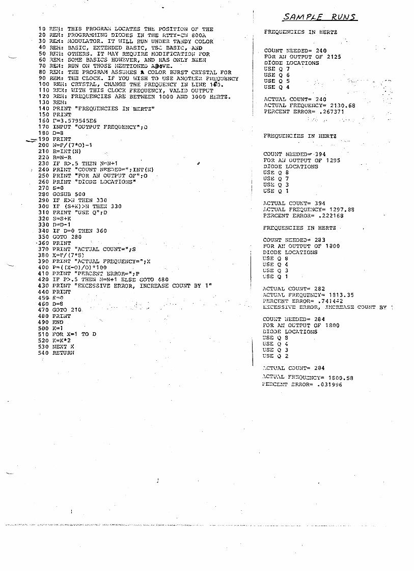
10 P..E!:l: THIS PROGRPJ'l LOCATES THE POSITION O? THE 20 RE.. ... l: PROGRA.'I£UNG DIO:JES IN THE RTTY-CW SODA 30 RE.."1: i.,IODULATOR. IT ~'lILL RUN UNDER TA!.'JDY COLOR 40 ~i: BASIC, EXTENDED BASIC, TS~ BASIC, ~~D 50 Rm-l: OTI-IEns. IT HAY REQUIRE HODIFICATlot~ FOR 60 ::\E~1: SO~1E BASICS HONZVER, AND HAS ONLY Bl!:EN' 70 RE~·l: RUN ON THOSE HEUTIOHED A8IOVE .. 80 RDl: THE PROGRAl-1 ASSUHES 1 COLOR BURST CRYSTAL FOR 90 REM: THE CLOCK. IF YOU ~-iISH TO USE ANOTEER FREQUENCY 100 RE'·l: CRYSTAL, CHANGE THE FREQVE:-lCY IN LINE 1 Do. 110 RE:1: ~"1ITH THIS CLOCK FREQUENCY, VALID OUTPt;T 120 REa: FREQUENCIES ARE BETtffiEN 1000 AND 3000 HERTZ. 130 REN: 140 PRINT "FREQU:r::NCIES IN HERTZ" 150 PRINT 160 P=3. 579545E6 170 INPUT "OUTPUT FREQUENCY";O 180 D=8
~190 PRINT 200 N=F/(7*0)-1 210 R=INT(N) 220 R=N-R 230 IF R>.5 THEN N=N+1 240 PRINT "COUNT NEEDED=II; INT on 250 PRINT "POR AN OUTPUT op"; 0 260 PRINT "DIODE LOCATIONS" 270 s=o 280 GOSUB 500 290 IF K> .. THEN 330 300 IF (S+;<»N THE:I 330 310 PRINT "USE QII;D 320 S=S+K 330 D=O-l 340 IF 0=0 THEN 360 350 GOTO 280
-360 PRINT 370 PRINT "ACTUAL COUNT=";S 380 X=F/(7*S) 390 PRHU "ACTUAL FREQUENCy=n iX 400 P=((X-O)/O)*100 410 PRINT "PERCENT ERROR="; P 420 IF P>.5 THEN N=N+1 ELSE GOTO 480 430 PRINT "EXCESSIVE ERROR, INCREASE COUNT BY 1· 440 PRINT 45{)- S~('!
460 o=B 470 GOTO 210 480 PiUi-JT 490 END 500 K=l 510 FOR X=l TO D 520 ](=](*2 530 tlEXT x 540 RETURl-l
Sf}M P;"£ RUNS
FREQutNCltS IN HERTZ
COUNT NEEDED= 240 FOR All OUTPUT OF 2125 DIODE LOCATIONS USE Q 7 USE Q 6 USE Q 5 USE Q 4
ACTUAL COUNT= 240 ACTUAL FREQUEllCY= 2130.68 PEaCENT ERROR= .267371
FREQUENCIES IN HERTZ
COUNT NEEDED= ·394 FOR Ail OUTPUT OF 1295 DIODE LOCATIONS USE Q 8 USE Q 7 USE Q 3 GSE Q 1
ACTUAL CDUNT= 394 ;,CTW\L FREQUENCY= 1297.88 PE~CENT ERROR= .222168
FREQUENCIES IN HERTZ
COUNT NEEDED= 283 FOR Al! OUTPUT OF 1800 DIODE LOCATIONS USE Q 8 USE Q 4 L:SE Q 3 USE Q 1
ACTUAL COUlIT= 282 .::"CTU.:"\.L FREQUENCY= 181 3.35 PERCENT ERROR= .741442 £:{CESSI\'E E!lROR, INCP.E]}.SE- CGUNT BY ~
COU~;T ~~EEDr:D= 284 FOR All OGTPUT OF 1 soo D10:>£ LOC-"...TIONS ~SE Q 8 USE Q <\ usz Q 3 USE Q 2
....... CTUAL COU~T= 284
."\CTU.\L FRSQUENCY= 1 SOD. 58 l'EI~CD!T ERROR= .031996

10 'THIS PROGRAM LOCATES THE POSITION OF THE 20 'PROGRAMMING DIODES IN THE RTTY-CW BOOA ::;0 '~10DUUHOF:. IT WILL fWN UNDER COLOR EXTENDED 4(' ' B{4SIC. THE F'F:OGF:At1 ASSUMES ,q COLOR BUF:3T -0 ' CFNSTAL FOR THE Cl_On<. IF ANOTHEF: CI":YST,o,L_ IS
,---,-,0 ' USED ~ CHANGE THE FREQUENCY O!\i LINE 160 .. 70 'WITH THIS CLOCK, VALID OUTPUT FI":EQUENCIES BO 'ARE BETWEEN 1000 AND 3~OO HZ. 90 100 F'R I NT "FI":EQUENC I ES IN HEI":TZ" 110 PF:INT 160 F=~;:: .. 579545E6 170 INPUT"OUTPUT Fr~EQUENCY" ~ 0 180 D:::::8m 190 PR I I\!T#"-2 200 N-F!17.'OI-1. 210 I":'''INT INI 220 P~;::N-R
230 IF 1":>.5 THEN N-N+1. 235 PRINT#-2, f'FREQUENCY::::: 11;O~11 HZI! 240 PI":INT#-2, "COUNT NEEDED=";INTINI 250 PI":INT#--2, "FOR AN OUTPUT OF"; 0 260 PHINTlf-·2, "DIODE LOCATIONS" 270 S:~~O
280 GOSUB 500 290 IF K)N THEN 330-300 IFIS+K»N THEN 330 310 P~~INT#--2~ nUSE [)II; D 320 8:::=S+t::: 330 D-D···-1
40 IF D-O THEN 370 ''-:-5~50 GO TO 280
370 PfH NT#--2" "ACTUAL COUNT"'-"; S ::,80 X=F! 17. 1<SI 390 F'RINT#-2, "ACTUAL FF:EQUENCY-"; X 400 P=(X-O)!O)*100~ 4·10 PH I NT#-2, "F'EF:CENT EF:F:OH-"; P . 420 IF P>.5 THEN N=N+l ELSE GOTO 480 4-30 F'PINT#--'2, "EXCESSIVE EF:FWF:" 440 F'F{ INT#-2, II II
450 S:::::O l+60 D:::::8 ~ 4·70 GO TO 210 4[10 PF:INT il·85 GOTO 17"0 490 END 500 ~:::;:::::I."
510 FOP X'=l TO D 520 t:::==r<*2. 5.30 NEXT X ;:540 RETUEN

FREQUENCY= 2125 HZ COUNT NEEDED= 240 FOR AN OUTPUT OF 2125 D lODE LOCl'tT I (lNS Uf5E Q 7
SE Q 6 '---.;;:tSE iJ 5
USE Q 4 ACTUAL COUNT- 240 ?'~CTUAL FF:EQUEi"~CY;;::: 2130 m 68155 PERCENT ERROR- .267366926
FREQUENCY= 2295 HZ COUNT NEEDED- 222 FOR AN OUTPUT OF 2295 DIODE LOCATIONS USE Q 7 USE Q 6 USE Q 4 USE Q 7 . ..;,
USE Q 2 IY3E Q ,
" ACTUAL COUNT= 222 ACTUAL FREQUENCY- 2303.43951 PERCENT ERROR- .367734697
FREQUENCY- 2550 HZ COUNT NEEDED"" 200 FOR AN OUTPUT OF 2550 DIODE LOCATIONS liSE Gl 7
'-~ .3E Q 6
USE Q ~;
ACTUAL COUNT- 200 ACTUAL FREQUENCY- 2556.81786 PERCENT ERROR= .267366933
FREQUENCY= 2975 HZ COUNT NEEDED= 171 FOR AN OUTPUT OF 2975 DIODE LOCATIONS USE Q 7 USE Q 5 USE Q 3 USE Q 1 ACTUAL COUNT- 170 ACTUAL FREQUENCY= 3008.02101 PERCENT ERROR= 1.10994987 EXCESSIVE ERROP
FREQUENCY= 2975 HZ COUI\lT NEEDED- 1 T':: FOR ,;N OUTPUT OF 2975 D IDDE LOC(iT lONe; USE Q "7
USE Q 5
'--uSE El :;;: ACTUAL COUNT- 172 ACTUAL FREQUENCY- 2973.04402 PERCENT EPPOP=-.065747237
FPEQUENCY= 1000 HZ COUNT NEEDED= 510 FeR -AN- BUTPtJT Df'~- H,oer D lODE LOCATION" USE Q 8
•

!
( FRO"'T PAf./Et. O£TIIII.S JI ~ C.-rB-/ CABIN£'i (
,wJ :rr $£ TI? /11/1 M t f) _____ . ________ ... ____ . . ... _______ .£~O~ L4/tG£.Mt:7E 1<."/ FRO", T to/ P .. _.__________ . __ ... _ -==-tt--....., _I
. A,,:> (t50 . ,'" SPEe,.,L= oJ £
170-'ff:S~».SPtCIAt.e;. I~AC£. CiJJt=1£J~ro VA~-~,,:\ ,(. \2!Y
/..£I/£/.. S£.r
(f;) /.. () c.!<.. '" Vt- [.
@ Mm"£.1
N~OW TUN£.
(L) , fb w /(7£ 1«-1<~)F3T 1>1)DT
6/11F'/ $£t$VI imy}w ()rJ RTry ~/oR. F~'fEf? SlOW -'lvra
EB c:w KEy
CO \.Ij(:i·) 01/1 FIlST" 0'" vPDT SP::;T 5TST"
OFF (f) 011 (Jj (±) U3 ({) (J) PTT CW REV
')PSi. DPtif SPbl MI~ ::;FsT ::sPDT
.~--- ._--.. -----_ .. _- •. - - ... --- -.-._" ...... _--.-.,. __ .. ----~---.~-------.------". ~---.----- -'" --..........• --_._----
McTe- R 5P~C£
'"
'i>VG-&£'ST£D FfWtJT PAA/£/..· I-lIyOtJ r. £NOUC-H SP-4C€. 15
IJJ-./..()Gv (i.() FOr<- TH£ RAOlo SII-4Ctl:- MEn/(, f}- fl/AR.R.Ow
£OC-£tvlf£ M£.T&t. f-vout-i? i5£ :£.0£4'- RPi? .414l ... o~ J.£5S "
C«<Jc...>OIA/(;.. (!)F SI.#/fC..r+e5. $M4t..t-e(2.. POTS ,ljNP FI{£61Ve/f/CY
5eLECT :;evtrc.ff ("d()U(.P FfJ:.-SO At-L.Qt.../ MtJ;ee: S'I'7AcE.
,t,
lIMIT
CD cw @ M-4RK.
{:B sPACE
@
-f-C1l8/tllir F({o}.)] L/ f>
, , .. ,":
l

I )... I
~I<J I 1
eo~\\. I I 5~~- I
, I
I I
I II I ' I I ,
. ' ! 1
I I
, II I I I I i j
i:; " _ _ ~S
! ~ t>
Ii C(
i ~ I~~ Ii! '
1
WI 81
8 8 G
I 81
I
!
(Bl I I
80' I
- --
; I
I I I
I 1
i i I i I
I ! I

"
PHOTOGRAPHS OF THE PROTOTYPE These three pictures will give you some ideas on panel layout. Not shown are the lock control, the wide/narrow switch, and the meter function switch. Note that the LED's at the right don't protrude very far into the cabinet; there is a post right behind them on the top cover of the box. There is also a LED for lock detect. It is no longer used. The meter lock null function is a much more sensitive indication. Note that the Radio Shack meter is used, and the top lip of the cabinet is trimmed to allow it to fit.
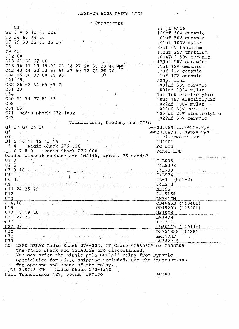
C'I'l
""'" 3 4 5 10 1 1 C6 54 63 79 80 C7 29 30 32 35 C8 C9 45 C12 60 C13 41 66 67 68 C15 16 17 18 19 c42 43 44 52 53 C84 85 86 87 88 C21 25 C22 26 62 64 65 C31 33 C34 C50 51 74 77 81 C5a C61 83
C'I'2
36 37
20 23 2-4 55 56 57 89 90
69 70
82
C71 ~adio Shack 272-1032 C83
AFSK-CH 800A PARTS LIS'I'
Capacitors
- -
27 -28 38 39 40-~ 59 72 73 _"X 78
Ik
,
33 pf l'lica 100pf 50V ceramic .01uf 50V ceramic .01uf 100V mylar 22uf 6V tantalum 1.0uf 25V tantalum .0047uf 50V ceramic 470pf 50V ceramic :luf 12V-ceramic .1uf 12V ceramic .luf12V ceramic 220pf mica .OOluf 50V ceramic .00luf 100v mylar luf 16V electrolytic 10u£ 16V electrolytic .022uf 100v mylar .022uf 50V ceramic 1000uf 25V electrolytic .022uf 50V ceramic
Transistors, Diodes, and IC's Q2 <23 Q4 Q6 Ql
Q5 \27 Dl 2 10 11 12 13 14 T'l 4 Radio Shack 276-026
6 7 8 9- Radio Shack 276-068
NPN 2[<508 9 f.>~,~ 400 Eo loopA
PNP 2H 5087 i?>"""'" '" iA5rJ If!- i001' fr TIP120 6U~.<erVT (_oof
11<4001 PC LED Panel LED
Diodes wi:tl'ou ~ number JL_j!£.~ .. J N!1~~_~Q~.!.. __ 1.~ .. Jl© .. ~d©sl u1 7 74LSOS
74LS393 U2 5 U3 9 10-U4 U6 31
_llL ___ ~ ______ .. __ ~ ___ .. _____ _ Ul1 24 25 29 u12 U13 U14,16 U15
..J!l]_...11l._12 ... .2L_ U21 22 23 U26 U27 _ .. _..,2",8 __ U30 U32
____ .......!.7.!i4 .... Ll2.SlJ,.O Oll-_. __ . ____ ~ __ ... __ 74LS74 IL-l (HCT-2) 74LS10 NE555 74LS164
_____ ... ___ .~Ll!±:',lw7,::4!..1_1~ CN . ____ ... __________ . __ ._ .. CD4046B (14046B) CD4S20B (14520B)
_______ -=:I1"'F:c:1c"!-0~ ________ ... _ LN348N XR2211 CD4.o 1 1 B (14 0 1 1 B l
..i!)l __ . _______ ~ HY REED ReLAY Radio Shack 275-228, CP Clare 925AOS2A
The Radio Shack and 925A052A are discontinued,
DS75188N (1488) L1317BP
__________________ ~--------__ ~~LM~342-£P~-d5---or MRB2A05
You may order the single pole HRB1A12 relay from Dynamic Specialties for $6.50 ship?ing included. See the instructions for options and_usage of the relay.
:AL 3.5795 NHz Radio Shack 272-1310 liall Transformer 12V, 500mA Jameco ACSOO

AFSt(-c.".1 800A PAR'rS LIST Resistors, Trimpots, and Inductor
All resistors 1/4 \.;att unless noted, values in ohr.\s ,{1 2 3 4 9 15 18 19 20 21 28 29 111 127 128 173 1!5 6 7 8 12 22 23 24 25 42 43 57 87 R117 122 124 129 152 15'j 183 R10 11 13 14 26 27 50 53 80 83 n16 32 55 56 58 59 63 67 68 69 73 77 85 86 88 89 R93 97 98 99 103 107 121 156165 175 177 181 182 R17 P.30 54 R31 38 R33 52 R34 35 R36 37 R40
78 39
79 84 108 116 126 140 143 144 145 160
82 180 157 51 81
R41 11 9 1 47 1 51 R60 66 70 76 90 96 100 106 R62 64 72 74 92 94 102 104 1\110 1<112 H113 171 R114 R115 R11S R120 R123 R125
169 162 155 179
174
R141 142 146 150 R148 149 R154 1<158 R159 185 R164 R1G6 172 R167 R168 R178 R184 F186 R187 1'.188 R45 163 R61 65 71 75 91 95 101 105 R44 RADIO SHACK 271-1714 R109 RADIO SjiACI( 271-1720 R170 RADIO SHACK 271-1715 L 1 (see instructions)
I !
S1 2 POLE 6 POSITION Radio Shack 275-1386
,5.1K 1K 1K 2K 100K 100K 33 10K 220K 51K 56K 82K 8.2K 620 11K 7.5K 1.5K 9.1 K 24K 16K 15K 1 MEG 2.7K 20K 470 6.8K 33K 4.7K 1.2K 2.2K 7.5 l"lEG 470K 27K 240K 180K 330 39 1/2 WATT 1. 8K 3.3K 10K TRHIPOT 2K TRIHPOT
5K PANEL CONTROL 5K PANEL CONTROL
10K PANEL CONTROL 10 uH or bead
5251011 DPDT Radio Shack 275-614, Jameco F'1'N01/JNT123 S3 4 6 7 8 9 SPDT Radio Shack 275-613, Jameco F'l'D01/JI1T223 .-11 (see instructions) 50 or 100 uA meter CABHIET (froll! Jameco Electronics) CBT-1
suggested parts sources Jarneco Electronics (415) - 592-8097 Digi-Key Corp. 1-800-346-5144 Fuji-Seva Inc. 800-421-2841