Features of the Slide Rail - THK Features and Types Slide Rail Features of the Slide Rail Fig.1...
42
Features and Types Slide Rail Features of the Slide Rail Fig.1 Structure of Slide Rail Model FBL Structure and Features Slide Rail model FBL is a thin, compact, lightweight and ultra-low price slide unit for finite motion. It has two rows of balls placed between an inner rail (made of a steel sheet roll-formed with precision) and an outer rail. The balls are evenly spaced by a cage press-molded with precision, thus eliminat- ing friction between balls and achieving a smooth slide mechanism. Since model FBL achieves smooth straight motion with easy installation, it can be used in a wide range of applications such as photocopiers, measuring instruments, telecommunication equipment, medical equipment, automatic vending machines and various types of office equipment. [Unit Type That Allows Easy Installation] Since the clearance and the motion of the slide unit are optimally adjusted, simply mounting the unit onto the base or the table using screws will achieve a slide mechanism with virtually no running noise. [Thin and Compact] Since the sectional shape is thin designed, this slide pack only requires a small side space for instal- lation. In addition, a desired number of slide pack units can be installed in parallel according to the load conditions. [Maintenance-free Operation] Since the slide rail is treated with zinc plating, it is highly corrosion resistant. In addition, the slide unit contains lithium soap-based grease, which is highly stable against oxidation. Outer rail Cage Ball Inner rail BERG AB тел. (495) 727-22-72 [email protected] www.thk.ru
Transcript of Features of the Slide Rail - THK Features and Types Slide Rail Features of the Slide Rail Fig.1...

A-646
Features and Types Slide Rail
Features of the Slide Rail
Fig.1 Structure of Slide Rail Model FBL
Structure and Features
Slide Rail model FBL is a thin, compact, lightweight and ultra-low price slide unit for finite motion. Ithas two rows of balls placed between an inner rail (made of a steel sheet roll-formed with precision)and an outer rail. The balls are evenly spaced by a cage press-molded with precision, thus eliminat-ing friction between balls and achieving a smooth slide mechanism.Since model FBL achieves smooth straight motion with easy installation, it can be used in a widerange of applications such as photocopiers, measuring instruments, telecommunication equipment,medical equipment, automatic vending machines and various types of office equipment.
[Unit Type That Allows Easy Installation]Since the clearance and the motion of the slide unit are optimally adjusted, simply mounting the unitonto the base or the table using screws will achieve a slide mechanism with virtually no runningnoise.
[Thin and Compact]Since the sectional shape is thin designed, this slide pack only requires a small side space for instal-lation. In addition, a desired number of slide pack units can be installed in parallel according to theload conditions.
[Maintenance-free Operation]Since the slide rail is treated with zinc plating, it is highly corrosion resistant. In addition, the slide unitcontains lithium soap-based grease, which is highly stable against oxidation.
Outer rail
Cage
Ball
Inner rail
BERG AB тел. (495) 727-22-72 [email protected]

A-647
Features and Types Types of the Slide Rail
Slide Rail
Types of the Slide RailTypes and Features
[Single Slides for Light Load]
Model FBL 27S Specification Table⇒B-542The most compact slide rail from THK.
Model FBL 27S
Model FBL 27S-P14 Specification Table⇒B-543An inner rail pulling type of model FBL 27S.Releasing the automatic free disconnectionspring attached on the inner rail allows the sliderail to be pulled out. When stored, the spring isautomatically released unidirectionally under acertain pressure.
Model FBL 27S-P14
Model FBL 35S Specification Table⇒B-544A single slide type of Slide Rail with the mostfundamental shape.
Model FBL 35S
BERG AB тел. (495) 727-22-72 [email protected]

A-648
Model FBL 35M Specification Table⇒B-545An inner rail pulling type of model FBL 35S. Itstops by frictional resistance when the slide railis fully opened, and is pulled out when beingpulled further with force.(brake-stop type)
Model FBL 35M
Model FBL 35J Specification Table⇒B-546Based on model FBL 35M, this model has alead ball that serves as a guide when the innerrail is inserted.
Model FBL 35J
Model FBL 35J-P13 Specification Table⇒B-547An inner rail pulling type of model FBL 35S.Releasing the disconnection spring attached onthe inner rail allows the slide rail to be pulledout. When folded, the locked state with the dis-connect spring is manually released.
Model FBL 35J-P13
BERG AB тел. (495) 727-22-72 [email protected]

A-649
Features and Types Types of the Slide Rail
Slide Rail
Model FBL 35J-P14 Specification Table⇒B-548An inner rail pulling type of model FBL 35S.Releasing the automatic free disconnectionspring attached on the inner rail allows the sliderail to be pulled out. When stored, the spring isautomatically released unidirectionally under acertain pressure.
Model FBL 35J-P14
Model FBL 35B Specification Table⇒B-549A brake-stop type of model FBL 35M. It can bemounted on the bottom face of a moving objectwhen used.
Model FBL 35B
BERG AB тел. (495) 727-22-72 [email protected]

A-650
[Single Slides for Medium Load]
Model FBL 35T Specification Table⇒B-550A single slide combining two units of model FBL35S. When folded, the locked state with the dis-connect spring is manually released.
Model FBL 35T
[Double Slides for Light Load]
Model FBL 27D Specification Table⇒B-551A double-slide type that combines two units ofmodel FBL 27S back-to-back. It is widely usedin various types of OA equipment.
Model FBL 27D
Model FBL 35E-P14 Specification Table⇒B-552A three-rail, double-slide type that allows a longstroke in a small space. Releasing the automaticfree disconnection spring attached on the innerrail allows the inner rail to be pulled out. Whenfolded, the locked state is automaticallyreleased under a certain pressure in the foldingdirection.
Model FBL 35E-P14
BERG AB тел. (495) 727-22-72 [email protected]

A-651
Features and Types Types of the Slide Rail
Slide Rail
[Double Slides for Medium Load]
Model FBL 35G-P13 Specification Table⇒B-553A double-slide type that combines two units ofmodel FBL 35S front-to-front. Releasing theautomatic free disconnection spring attached onthe inner rail allows the inner rail to be pulledout. When folded, the locked state with the dis-connect spring is manually released. It is alsoequipped with a pull-lock mechanism that func-tions when the slide rail is fully opened.
Model FBL 35G-P13
Model FBL 35G-P14 Specification Table⇒B-554A double-slide type that combines two units ofmodel FBL 35S front-to-front. Releasing theautomatic free disconnection spring attached onthe inner rail allows the inner rail to be pulledout. When folded, the lock state with the discon-nect spring can automatically be released undera certain pressure in the folding direction. It isalso equipped with a pull-lock mechanism thatfunctions when the slide rail is fully opened. Model FBL 35G-P14
Model FBL 35D Specification Table⇒B-555A double-slide type that combines two units ofmodel FBL 35S back-to-back. It is extensivelyused regardless of the industry.
Model FBL 35D
Model FBL 35W Specification Table⇒B-556A double-slide type based on model FBL 35Sthat achieves a thickness of one single-slideunit.
Model FBL 35W
BERG AB тел. (495) 727-22-72 [email protected]

A-652
Model FBL 51H Specification Table⇒B-557A three-rail, double-slide type that allows for along stroke. With the smallest thickness, thismodel can be used in a space-saving locationeven under a large load.
Model FBL 51H
Model FBL 51H-P13 Specification Table⇒B-558A three-rail, double-slide type that allows a longstroke. With the smallest thickness, this modelcan be used in a space-saving location evenunder a large load. Releasing the automatic freedisconnection spring attached on the inner railallows the inner rail to be pulled out. Whenfolded, the locked state with the disconnectspring is manually released. It is also equippedwith a lock mechanism that functions when theslide rail is fully opened.
Model FBL 51H-P13
Model FBL 51H-P14 Specification Table⇒B-559A three-rail, double-slide type that allows a longstroke. With the smallest thickness, this modelcan be used in a space-saving location evenunder a large load. Releasing the automatic freedisconnection spring attached on the inner railallows the inner rail to be pulled out. Whenfolded, the locked state is automaticallyreleased under a certain pressure in the foldingdirection.
Model FBL 51H-P14
BERG AB тел. (495) 727-22-72 [email protected]

A-653
Features and Types Types of the Slide Rail
Slide Rail
[Double Slides for Heavy Load]
Model FBL 35K Specification Table⇒B-560A double-slide type combining 4 units of modelFBL 35S. It achieves the largest permissibleload among all types and is optimal for opening/closing heavy objects.
Model FBL 35K
Model FBL 56H Specification Table⇒B-561A double-slide type with the largest permissibleload among the three rails. It is used extensivelyin various types of OA furniture.
Model FBL 56H
Model FBL 56H-P13 Specification Table⇒B-562A double-slide type with the largest permissibleload among the three rails. Releasing the auto-matic free disconnection spring attached on theinner rail allows the inner rail to be pulled out.When folded, the locked state with the discon-nect spring is manually released. It is alsoequipped with a lock mechanism that functionswhen the slide rail is fully opened.
Model FBL 56H-P13
Model FBL 561H-P14 Specification Table⇒B-563A double-slide type with the largest permissibleload among the three rails. Releasing the auto-matic free disconnection spring attached on theinner rail allows the inner rail to be pulled out.When folded, the locked state is automaticallyreleased under a certain pressure in the foldingdirection.
Model FBL 56H-P14
BERG AB тел. (495) 727-22-72 [email protected]

A-654
[Linear Type Slides]
Light Load Type Model FBL 35F Specification Table⇒B-564Using a flange type that can easily be mounted,this slide-type model is capable of performingstraight, finite motion.
Light Load Type Model FBL 35F
Medium Load Type Model FBL 56F Specification Table⇒B-565Using a flange type that can easily be mounted,this slide-type model is capable of performingstraight, finite motion. It is optimal for locationsunder a large working load.
Medium Load Type Model FBL 56F
Heavy Load Type Model FBL 48DR Specification Table⇒B-566A heavy-load, low-friction slide rail developedfor sliding heavy doors.
Heavy Load Type Model FBL 48DR
BERG AB тел. (495) 727-22-72 [email protected]

A-655
Features and Types Types of the Slide Rail
Slide Rail
[Aluminum Alloy Slide Rail]
Light Load Type Model E15 Specification Table⇒B-567The lightest and most compact single slide inthe aluminum alloy series. It is especially suit-able for locations with magnetism, locationsrequiring antirust measures and locations wheremuch importance is given to appearance.
Light Load Type Model E15
Light Load Type Model E20 Specification Table⇒B-568A single-slide with the most fundamental shapein the aluminum alloy series. It is especially suit-able for locations with magnetism, locationsrequiring antirust measures and locations wheremuch importance is given to appearance.
Light Load Type Model E20
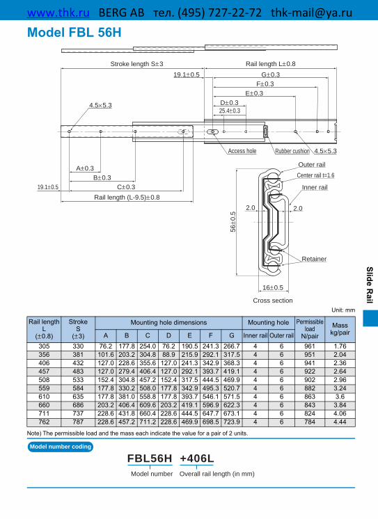
Light Load Type Model D20 Specification Table⇒B-569The lightest and most compact double slides inthe aluminum alloy series. It is especially suit-able for locations with magnetism, locationsrequiring antirust measures and locations wheremuch importance is given to appearance.
Light Load Type Model D20
BERG AB тел. (495) 727-22-72 [email protected]

A-656
Classification Table for Slide Rails
Model FBL27S
Model FBL27S-P14
For Light Load
Single Slide Double Slide
Slide Rail
Model FBL35J
Model FBL35J-P13
Model FBL35J-P14
For Medium LoadModel FBL35T
Model E20
For Heavy Load
Model FBL35K
Model FBL35S
Model FBL27D
For Light LoadModel FBL35E-P14
Model D20
Model FBL35M
Model FBL35B
Model E15(Made of Aluminum)
(Made of Aluminum)
(Made of Aluminum)
Model FBL56H
Model FBL56H-P13
Model FBL56H-P14
9.5
27
9.5
35.3
9.5
35.3
5
15
9.5
35.3
33
48.5
12.7
71.4
8
20
23.9
71.4
16
56
13
35.3
27
19.1
16
20
BERG AB тел. (495) 727-22-72 [email protected]

A-657
Features and Types Classification Table for Slide Rails
Slide Rail
Linear Type Slide
Model FBL35G-P13
Model FBL35G-P14
For Medium Load
For Medium LoadModel FBL56F
For Heavy LoadModel FBL48DR
For Light LoadModel FBL35F
Model FBL35D
Model FBL51H
Model FBL51H-P13
Model FBL51H-P14
Model FBL35W
12.7
81.3
12.7
51.5
35.3
19.1
35.3
19.1
14
56
14.6
48
11.1
35.3
BERG AB тел. (495) 727-22-72 [email protected]

A-658
Mounting Procedure and Maintenance Slide Rail
Mounting the Slide Rail[Mounting Screws of the Slide Rail]The slide rail is designed to be mounted usingM4 screws. Since the mounting space is smallas shown in Fig.1, we recommend using button-head bolt or binding-head bolt (JIS B 1111annex).Note) For models FBL27S/27S-P14/27D, use M4 binding-
head bolt, or M3 button-head bolt or binding-head bolt.Note) For model FBL48DR, use M5×8 mounting screw.Note) For model E15, use M2.6 countersunk screw.Note) For models E20 and D20, use M3 countersunk screw.Note) For model FBL 35E, use M3 button-head bolts or bind-
ing-head bolts.
Fig.1
[Attaching the Slide Rail]While keeping the maximum stroke, mount theouter rail at the section where the inner rail andthe outer rail overlap, slide the inner rail back-ward, and then secure the rail using a screwthrough the access hole.
Fig.2
[Permissible Load and Mounting Orientation]For use other than with the mounting orientationshown in Fig.3, contact THK.The permissible load of the Slide Rail indicatesthe load in the direction Pa that two rails canreceive in the middle of the inner rail length atthe maximum stroke.
Fig.3
[Surface Treatment]The surface of the Slide Rail is treated with electro-galvanizing (gloss chromate treatment) as stan-dard. Colored chromate treatment and chrome plating are also available. Contact THK for details.
Access hole
Top
Bottom
PaPa
BERG AB тел. (495) 727-22-72 [email protected]

A-659
Precautions on Use Slide Rail
Slide Rail
00[Handling](1) Tilting a slide rail may cause it to fall by its own weight.(2) Dropping or hitting the Slide Rail may damage it. Giving an impact force to the slide rail could
also cause damage even if the product looks intact.
[Precautions on Use](1) When mounting the Slide Rail, use care to always keep both rails in parallel.(2) Entrance of foreign material may cause damage to the Slide Rail or functional loss.(3) Avoid using the product at other than normal temperature, or using it in harsh conditions such as
intensive reciprocations that generate frictional heat and environments with water or dust.(4) The durability of the Slide Rail varies depending on factors such as the drawing dimension,
travel distance, mounting conditions and environment in addition to operating frequency. Takethese factors into account when making a selection.
[Storage]When storing the Slide Rail, avoid high temperature, low temperature and high humidity.
BERG AB тел. (495) 727-22-72 [email protected]

B-542
Model FBL 27S
Unit: mm
Note) The permissible load and the mass each indicate the value for a pair of 2 units.
Model number coding
Rail lengthL
(±0.8)
StrokeS
(±3)
Mounting hole dimensions Mounting hole Permissible load
N/pairMass
kg/pairA B C D E Inner rail Outer rail
200 135 140.0 160.0 — 140.0 160.0 5 5 260 0.32250 185 190.0 210.0 150.0 190.0 210.0 6 5 240 0.40300 222 240.0 260.0 190.0 240.0 260.0 6 5 240 0.48350 260 290.0 310.0 225.0 290.0 310.0 6 5 230 0.56400 297 340.0 360.0 265.0 340.0 360.0 6 5 210 0.64450 334 390.0 410.0 300.0 390.0 410.0 6 5 200 0.72500 371 440.0 460.0 337.0 440.0 460.0 6 5 180 0.80
Rail length (L-3)±0.8
Stroke length S±3
Access hole
2-φ 4.5 (both ends)
2-φ 4.5 (both ends)
Access hole
Rail length L±0.8
Retainer
Inner rail
Outer rail
Cross section
C±0.3
E±0.3D±0.3
20±0.5
100±0.320±0.3
4.2×6
4.2×6
100±0.320±0.3
B±0.3A±0.3
20±0.5
9.5±0.5
27±0
.5 1.61.6
Overall rail length (in mm)Model number
FBL27S +300L
BERG AB тел. (495) 727-22-72 [email protected]

B-543
Slide Rail
Model FBL 27S-P14
Unit: mm
Note) The permissible load and the mass each indicate the value for a pair of 2 units.
Model number coding
Rail lengthL
(±0.8)
StrokeS
(±3)
Mounting hole dimensions Mounting hole Permissibleload
N/pairMass
kg/pairA B C D E Inner rail Outer rail
200 116 65.0 — 170.0 140.0 160.0 4 5 260 0.32250 152 100.0 — 210.0 190.0 210.0 4 5 240 0.40300 202 100.0 — 260.0 240.0 260.0 4 5 240 0.48350 251 100.0 — 310.0 290.0 310.0 4 5 230 0.56400 297 100.0 — 360.0 340.0 360.0 4 5 210 0.64450 332 100.0 390.0 410.0 390.0 410.0 5 5 210 0.72500 371 100.0 440.0 460.0 440.0 460.0 5 5 200 0.80550 407 100.0 490.0 510.0 490.0 510.0 5 5 180 0.80
Rail length (L-3)±0.8
Automatic freedisconnection spring
2-φ 4.5 (both ends)
Stroke length S±3
Lead stick
Rail length L±0.8
2-φ 4.5 (both ends)Rubber cushion
Outer rail
Inner rail
Retainer
Cross section
C±0.320±0.5
A±0.320±0.3
B±0.3
4.2×6
20±0.5 E±0.3D±0.3
100±0.320±0.3 4.2×6
9.5±0.5
27±0
.5 1.6 1.6
Overall rail length (in mm)Model number
FBL27S-P14 +500L
BERG AB тел. (495) 727-22-72 [email protected]

B-544
Model FBL 35S
Unit: mm
Note) The permissible load and the mass each indicate the value for a pair of 2 units.
Model number coding
Rail lengthL
(±0.8)
StrokeS
(±3)
Mounting hole dimensions Mounting hole Permissible load
N/pairMass
kg/pairA B C D E F G Inner rail Outer rail
305 229 — 152.4 254.0 — 149.2 260.3 273.0 4 7 490 0.6356 279 — 203.2 304.8 — 200.0 311.1 323.8 4 7 400 0.7406 305 — 254.0 355.6 — 250.8 361.9 374.6 4 7 390 0.8457 330 203.2 304.8 406.4 212.7 301.6 412.7 425.4 5 8 380 0.9508 381 228.6 355.6 457.2 238.1 352.4 463.5 476.2 5 8 330 1.0559 406 254.0 406.4 508.0 263.5 403.2 514.3 527.0 5 8 320 1.1610 432 279.4 457.2 558.8 288.9 454.0 565.1 577.8 5 8 310 1.2660 483 304.8 508.0 609.6 314.3 504.8 615.8 628.6 5 8 280 1.3711 508 330.2 558.8 660.4 339.7 555.6 666.7 679.4 5 8 270 1.4
Outer rail
Inner rail
Retainer
Cross section
Stroke length S±3
Rail length (L-3)±0.8
Access hole
Rail length L±0.8
1.6 1.6
35.3
±0.5
9.5±0.5
4.5×5.34.5×5.3
G±0.3F±0.3
E±0.3D±0.3
111.1±0.3
25.4±0.312.7±0.3
15.9±0.5
25.4±0.5 C±0.3B±0.3
A±0.3101.6±0.3
Overall rail length (in mm)Model number
FBL35S +457L
BERG AB тел. (495) 727-22-72 [email protected]

B-545
Slide Rail
Model FBL 35M
Unit: mm
Note) The permissible load and the mass each indicate the value for a pair of 2 units.
Model number coding
Rail lengthL
(±0.8)
StrokeS
(±3)
Mounting hole dimensions Mounting hole Permissibleload
N/pairMass
kg/pairA B C D E F G Inner rail Outer rail
305 229 — 152.4 254.0 — 149.2 260.3 273.0 4 7 490 0.6356 279 — 203.2 304.8 — 200.0 311.1 323.8 4 7 400 0.7406 305 — 254.0 355.6 — 250.8 361.9 374.6 4 7 390 0.8457 330 203.2 304.8 406.4 212.7 301.6 412.7 425.4 5 8 380 0.9508 381 228.6 355.6 457.2 238.1 352.4 463.5 476.2 5 8 330 1.0559 406 254.0 406.4 508.0 263.5 403.2 514.3 527.0 5 8 320 1.1610 432 279.4 457.2 558.8 288.9 454.0 565.1 577.8 5 8 310 1.2660 483 304.8 508.0 609.6 314.3 504.8 615.9 628.6 5 8 280 1.3711 508 330.2 558.8 660.4 339.7 555.6 666.7 679.4 5 8 270 1.4
Stroke length S±3
Rail length (L-4)±0.8
Access hole
Rail length L±0.8
Outer rail
Inner rail
Retainer
Cross section
4.5×5.34.5×5.3
G±0.3F±0.3
E±0.3D±0.3
111.1±0.3
25.4±0.312.7±0.3
25.4±0.5 C±0.3B±0.3
A±0.3101.6±0.3
1.6 1.6
35.3
±0.5
9.5±0.5
15.9±0.5
Overall rail length (in mm)Model number
FBL35M +406L
BERG AB тел. (495) 727-22-72 [email protected]

B-546
Model FBL 35J
Unit: mm
Note) The permissible load and the mass each indicate the value for a pair of 2 units.
Model number coding
Rail lengthL
(±0.8)
StrokeS
(±3)
Mounting hole dimensions Mounting hole Permissible load
N/pairMass
kg/pairA B C D E F G Inner rail Outer rail
305 229 — 152.4 254.0 — 149.2 260.3 273.0 4 7 490 0.6356 279 — 203.2 304.8 — 200.0 311.1 323.8 4 7 400 0.7406 305 — 254.0 355.6 — 250.8 361.9 374.6 4 7 390 0.8457 330 203.2 304.8 406.4 212.7 301.6 412.7 425.4 5 8 380 0.9508 381 228.6 355.6 457.2 238.1 352.4 463.5 476.2 5 8 330 1.0559 406 254.0 406.4 508.0 263.5 403.2 514.3 527.0 5 8 320 1.1610 432 279.4 457.2 558.8 288.9 454.0 565.1 577.8 5 8 310 1.2660 483 304.8 508.0 609.6 314.3 504.8 615.9 628.6 5 8 280 1.3711 508 330.2 558.8 660.4 339.7 555.6 666.7 679.4 5 8 270 1.4
Lead ballAccess hole
Rail length L±0.8Stroke length S±3
Rail length (L-4)±0.8
Outer rail
Inner rail
Retainer
Cross section
4.5×5.3 4.5×5.3
G±0.3F±0.3
E±0.3D±0.3
111.1±0.3
15.9±0.5
25.4±0.312.7±0.3
25.4±0.5 C±0.3B±0.3
A±0.3101.6±0.3
1.6 1.6
35.3
±0.5
9.5±0.5
Overall rail length (in mm)Model number
FBL35J +660L
BERG AB тел. (495) 727-22-72 [email protected]

B-547
Slide Rail
Model FBL 35J-P13
Unit: mm
Note) The permissible load and the mass each indicate the value for a pair of 2 units.
Model number coding
Rail lengthL
(±0.8)
StrokeS
(±3)
Mounting hole dimensions Mounting hole Permissibleload
N/pairMass
kg/pairA B C D E F Inner rail Outer rail
305 224 152.4 — 136.5 — 247.6 260.3 3 6 490 0.6356 275 203.2 — 187.3 — 298.4 311.1 3 6 400 0.72406 315 254.0 — 238.1 — 349.2 361.9 3 6 390 0.84457 330 203.2 406.4 200.0 228.9 400.0 412.7 4 7 380 0.96508 381 228.6 457.2 225.4 339.7 450.8 463.5 4 7 330 1.04559 406 254.0 508.0 250.8 390.5 501.6 514.3 4 7 320 1.16610 432 279.4 558.8 276.2 441.3 552.4 565.1 4 7 310 1.24660 483 304.8 609.6 301.6 492.1 603.2 615.9 4 7 280 1.36711 493 330.2 660.4 327.0 542.9 654.0 666.7 4 7 270 1.48
Disconnection spring
Lead stickAccess hole
Rail length L±0.8Stroke length S±3
Rail length (L-4)±0.8
Outer rail
Inner rail
Retainer
Cross section
C±0.3
F±0.3E±0.3
D±0.3
98.4±0.312.7±0.3
28.6±0.5
4.5×5.3
4.5×5.3
25.4±0.5 B±0.3
A±0.3
101.6±0.3
1.6 1.6
35.3
±0.5
9.5±0.5
Overall rail length (in mm)Model number
FBL35J-P13 +559L
BERG AB тел. (495) 727-22-72 [email protected]

B-548
Model FBL 35J-P14
Unit: mm
Note) The permissible load and the mass each indicate the value for a pair of 2 units.
Model number coding
Rail lengthL
(±0.8)
StrokeS
(±3)
Mounting hole dimensions Mounting hole Permissibleload
N/pairMass
kg/pairA B C D E F Inner rail Outer rail
305 224 152.4 — 136.5 — 247.6 260.3 3 6 490 0.6356 275 203.2 — 187.3 — 298.4 311.1 3 6 400 0.72406 315 254.0 — 238.1 — 349.2 361.9 3 6 390 0.84457 330 203.2 406.4 200.0 228.9 400.0 412.7 4 7 380 0.96508 381 228.6 457.2 225.4 339.7 450.8 463.5 4 7 330 1.04559 406 254.0 508.0 250.8 390.5 501.6 514.3 4 7 320 1.16610 432 279.4 558.8 276.2 441.3 552.4 565.1 4 7 310 1.24660 483 304.8 609.6 301.6 492.1 603.2 615.9 4 7 280 1.36711 493 330.2 660.4 327.0 542.9 654.0 666.7 4 7 270 1.48
Automatic freedisconnection spring
Lead stickAccess hole
Rail length L±0.8Stroke length S±3
Rail length (L-4)±0.8
Outer rail
Inner rail
Retainer
Cross section
C±0.3
F±0.3E±0.3
D±0.3
98.4±0.312.7±0.3
28.6±0.5
4.5×5.3
4.5×5.3
25.4±0.5 B±0.3
A±0.3
101.6±0.3
1.6 1.6
35.3
±0.5
9.5±0.5
Overall rail length (in mm)Model number
FBL35J-P14 +559L
BERG AB тел. (495) 727-22-72 [email protected]

B-549
Slide Rail
Model FBL 35B
Unit: mm
Note) The permissible load and the mass each indicate the value for a pair of 2 units.
Model number coding
Rail lengthL
(±0.8)
StrokeS
(±3)
Mounting hole Permissible loadN/pair
Masskg/pairInner rail Outer rail
324 216 7 7 115 0.8375 267 7 7 105 0.92425 305 7 7 100 1476 318 7 7 90 1.12527 368 7 7 83 1.24578 419 7 7 73 1.32629 445 7 7 66 1.44679 495 7 7 61 1.6
Stroke length S±3 Rail length L±0.8
Mounting bracket
Rail length (L-4)±0.8 Mounting bracket
Cross section
Inner rail
Mounting bracket
Outer railRetainer
Mounting bracket
0 to 35
7.9
139.7
101.6
4.6×10.3
3– 4.2×9.5
4.6×5.33– 4.6×5.3
2– φ 4.3
3.7×6.44.8 12.7P11.6×4
41.46.54.7
63.5 213.9
3– φ 4.8
9.5±
0.5
(10
.5)
(37.3)35.3±0.5
2– φ 4.5
9.6
23.9
30.5
33
48.5
5.2×9.5
4.6×31.8
4–R4.5
4.6
6.8
(37.3)
Overall rail length (in mm)Model number
FBL35B +375L
BERG AB тел. (495) 727-22-72 [email protected]

B-550
Model FBL 35T
Unit: mm
Note) The permissible load and the mass each indicate the value for a pair of 2 units.
Model number coding
Rail lengthL
(±0.8)
StrokeS
(±3)
Mounting hole dimensions Mounting hole Permissibleload
N/pairMass
kg/pairA B C D E F Inner rail Outer rail
305 227 — 149.2 273.0 — 152.8 254.4 4 4 1120 2.16356 278 — 200.0 323.8 — 203.6 305.2 4 4 1070 2.56406 303 — 250.8 374.6 — 254.4 356.0 4 4 1020 2.96457 354 212.7 301.6 425.4 203.2 305.2 406.8 5 5 1000 3.3508 367 238.1 352.4 476.2 228.6 356.0 457.6 5 5 971 3.64559 430 263.5 403.2 527.0 254.0 406.8 508.4 5 5 922 4.04610 456 288.9 454.0 577.8 279.4 457.6 559.2 5 5 873 4.32660 468 314.3 504.8 628.6 304.8 508.4 610.0 5 5 843 4.72711 506 339.7 555.6 679.4 330.2 559.2 660.8 5 5 784 5.1
Rail length L±0.8Stroke length S±3
Rail length (L-3)±0.8
Access hole
Cabinet railDrawer rail
Retainer
Cross section
36.1
±0.5
4.5×5.3
C±0.3B±0.3
A±0.3111.1±0.3
15.9±0.5
(14.2)
F±0.3E±0.3
D±0.3101.6±0.3
25.4±0.5
4.5×5.3
12.7±0.8
71.4
±0.8
1.61.6
Overall rail length (in mm)Model number
FBL35T +559L
BERG AB тел. (495) 727-22-72 [email protected]

B-551
Slide Rail
Model FBL 27D
Unit: mm
Note) The permissible load and the mass each indicate the value for a pair of 2 units.
Model number coding
Rail lengthL
(±0.8)
StrokeS
(±3)
Mounting holedimensions Mounting hole Permissible
loadN/pair
Masskg/pair
A B Drawer rail Cabinet rail
200 229 140.0 160.0 5 5 370 0.64250 276 190.0 210.0 5 5 360 0.8300 327 240.0 260.0 5 5 350 0.96350 376 290.0 310.0 5 5 330 1.12400 426 340.0 360.0 5 5 310 1.28450 475 390.0 410.0 5 5 290 1.46500 524 440.0 460.0 5 5 280 1.6
2-φ 4.5 (both ends)Access hole
Cabinet railDrawer rail
Center railRail length L±0.8
Stroke length S±3 Rail length L±0.8
Cross section
Retainer
2-φ 4.5 (both ends)
4.2×6
20±0.5B±0.3A±0.3
100±0.320±0.3
20±0.5 B±0.3A±0.3
100±0.320±0.3
19.1±0.5
1.6
27±0
.5 1.6
4.2×6
Overall rail length (in mm)Model number
FBL27D +200L
BERG AB тел. (495) 727-22-72 [email protected]

B-552
Model FBL 35E-P14
Unit: mm
Note) The permissible load and the mass each indicate the value for a pair of 2 units.
Model number coding
Rail lengthL
(±0.8)
StrokeS
(±3)
Mounting hole dimensions Mounting hole Permissibleload
N/pairMass
kg/pairA B C D E F G Inner rail Outer rail
305 330 — 149.2 260.3 273.0 233.1 254.0 266.7 7 7 294 0.88356 381 — 200.0 311.1 323.8 258.5 304.8 317.5 7 7 284 1.04406 432 — 250.8 361.9 374.6 283.9 355.6 368.3 7 7 275 1.16457 483 212.7 301.6 412.7 425.4 309.3 406.4 419.1 7 8 255 1.32508 533 238.1 352.4 463.5 476.2 334.7 457.2 469.9 7 8 235 1.48
Rail length (L-11)±0.8
Stroke length S±3
Rubber cushionAccess hole
Rail length L±0.8
Automatic freedisconnection spring
Outer railCenter rail
RetainerInner rail
Cross section
15.9±0.5
12.7±0.325.4±0.3
101.6±0.3E±0.3F±0.3G±0.3
4.5×5.34.5×5.3
15.9±0.5
12.7±0.325.4±0.3
111.1±0.3A±0.3
B±0.3C±0.3D±0.3
1.6 24.9
15.31.61.6
35.3
±0.5
13±0.5
Overall rail length (in mm)Model number
FBL35E-P14 +508L
BERG AB тел. (495) 727-22-72 [email protected]

B-553
Slide Rail
Model FBL 35G-P13
Unit: mm
Note) The permissible load and the mass each indicate the value for a pair of 2 units.
Model number coding
Rail lengthL
(±0.8)
StrokeS
(±3)
Mounting hole dimensions Mounting hole Permissibleload
N/pairMass
kg/pairA B C D E F Drawerrail
Cabinetrail
305 327 — — — 260.3 273.0 — 5 6 623 1.2356 378 — — 298.4 311.1 323.8 — 6 6 586 1.4406 429 — — 349.2 361.9 374.6 250.8 6 7 555 1.6457 480 212.7 — 400.0 412.7 425.4 301.6 7 7 516 1.8508 530 238.1 365.1 450.8 463.5 476.2 352.4 8 7 475 2559 581 263.5 415.9 501.6 514.3 527.0 403.2 8 7 444 2.2610 632 288.9 466.7 552.4 565.1 577.8 454.0 8 7 413 2.4660 683 314.3 517.5 603.2 615.9 628.6 504.8 8 7 382 2.6711 734 339.7 568.3 654.0 666.7 679.4 555.6 8 7 355 2.8
Rubber cushion
Lock mechanismDisconnection spring
Rubber cushion
Access hole
Lead stick
Rail length (L-4)±0.8
Stroke length S±3 Rail length L±0.8
Cabinet rail
Center rail
Drawer rail
Retainer
Cross section
15.9±0.5
12.7±0.3
15.9±0.5
25.4±0.3111.1±0.3
4.5×5.3
4.5×5.3
A±0.3B±0.3
123.8±0.312.7±0.3
C±0.3D±0.3E±0.3
E±0.3D±0.3
F±0.3
19.1±0.5
35.3
±0.5 1.61.6
Overall rail length (in mm)Model number
FBL35G-P13 +356L
BERG AB тел. (495) 727-22-72 [email protected]

B-554
Model FBL 35G-P14
Unit: mm
Note) The permissible load and the mass each indicate the value for a pair of 2 units.
Model number coding
Rail lengthL
(±0.8)
StrokeS
(±3)
Mounting hole dimensions Mounting hole Permissibleload
N/pairMass
kg/pairA B C D E F Drawerrail
Cabinetrail
305 327 — — — 260.3 273.0 — 5 6 623 1.2356 378 — — 298.4 311.1 323.8 — 6 6 586 1.4406 429 — — 349.2 361.9 374.6 250.8 6 7 555 1.6457 480 212.7 — 400.0 412.7 425.4 301.6 7 7 516 1.8508 530 238.1 365.1 450.8 463.5 476.2 352.4 8 7 475 2559 581 263.5 415.9 501.6 514.3 527.0 403.2 8 7 444 2.2610 632 288.9 466.7 552.4 565.1 577.8 454.0 8 7 413 2.4660 683 314.3 517.5 603.2 615.9 628.6 504.8 8 7 382 2.6711 734 339.7 568.3 654.0 666.7 679.4 555.6 8 7 355 2.8
Rubber cushion
Lock mechanism
Automatic freedisconnection spring
Rubber cushion
Access hole
Lead stick
Rail length (L-4)±0.8
Stroke length S±3 Rail length L±0.8
Cabinet rail
Center rail
Drawer rail
Retainer
Cross section
15.9±0.5
12.7±0.325.4±0.3
111.1±0.3
4.5×5.3
4.5×5.3
15.9±0.5
A±0.3B±0.3
123.8±0.312.7±0.3
C±0.3D±0.3E±0.3
E±0.3D±0.3
F±0.3
19.1±0.5
35.3
±0.5 1.61.6
Overall rail length (in mm)Model number
FBL35G-P14 +610L
BERG AB тел. (495) 727-22-72 [email protected]

B-555
Slide Rail
Model FBL 35D
Unit: mm
Note) The permissible load and the mass each indicate the value for a pair of 2 units.
Model number coding
Rail lengthL
(±0.8)
StrokeS
(±3)
Mounting hole dimensions Mounting hole Permissibleload
N/pairMass
kg/pairA B C D Drawer rail Cabinet rail
305 327 — 149.2 260.3 273.0 7 7 588 1.28356 378 — 200.0 311.1 323.8 7 7 578 1.48406 429 — 250.8 361.9 374.6 7 7 559 1.72457 480 212.7 301.6 412.7 425.4 8 8 549 1.96508 530 238.1 352.4 463.5 476.2 8 8 529 2.12559 581 263.5 403.2 514.3 527.0 8 8 500 2.4610 632 288.9 454.0 565.1 577.8 8 8 480 2.56660 683 314.3 504.8 615.9 628.6 8 8 461 2.8711 734 339.7 555.6 666.7 679.4 8 8 441 3
Cabinet rail
Drawer rail
RetainerCenter rail
Cross section
Access hole
Rail length L±0.8
Rail length L±0.8Stroke length S±3
19.1±0.5
1.635
.3±0
.5 1.6
4.5×5.3
15.9±0.5D±0.3C±0.3
B±0.3A±0.3
111.1±0.325.4±0.312.7±0.3
15.9±0.5 D±0.3C±0.3
B±0.3A±0.3
111.1±0.325.4±0.312.7±0.34.5×5.3
Overall rail length (in mm)Model number
FBL35D +711L
BERG AB тел. (495) 727-22-72 [email protected]

B-556
Model FBL 35W
Unit: mm
Note) The permissible load and the mass each indicate the value for a pair of 2 units.
Model number coding
Rail lengthL
(±0.8)
StrokeS
(±3)
Mounting hole dimensions Mounting hole Permissibleload
N/pairMass
kg/pairA B C D Drawer rail Cabinet rail305 327 — 149.2 260.4 273.1 7 7 706 1.68356 378 — 200.0 311.2 323.9 7 7 676 2406 429 — 250.8 362.0 374.7 7 7 637 2.32457 480 225.4 301.6 412.8 425.5 8 8 598 2.64508 530 250.8 352.4 463.6 476.3 8 8 569 2.88559 581 276.2 403.2 514.4 527.1 8 8 520 3.2610 632 301.6 454.0 565.2 577.9 8 8 480 3.52660 683 327.0 504.8 616.0 628.7 8 8 422 3.84711 734 352.4 555.6 666.8 679.5 8 8 353 4.12
Drawer rail
RetainerCabinet rail
Center rail
Access hole
Access hole
Stroke length S±3 Rail length L±0.8
Rail length L±0.8
Cross section
4.5×5.3
4.5×5.3
D±0.3C±0.3
B±0.3A±0.3
111.1±0.325.4±0.312.7±0.3
15.9±0.5
D±0.3C±0.3
B±0.3A±0.3
111.1±0.325.4±0.312.7±0.3
15.9±0.5
35.3
±0.5
46±0
.5
81.3
±0.8
1.61.6
12.7±0.8
1.6
Overall rail length (in mm)Model number
FBL35W +356L
BERG AB тел. (495) 727-22-72 [email protected]

B-557
Slide Rail
Model FBL 51H
Unit: mm
Note) The permissible load and the mass each indicate the value for a pair of 2 units.
Model number coding
Rail lengthL
(±0.8)
StrokeS
(±3)
Mounting hole dimensions Mounting hole Permissibleload
N/pairMass
kg/pairA B C D E F G Inner rail Outer rail305 330 76.2 177.8 254.0 76.2 190.5 241.3 266.7 4 6 850 1.46356 381 101.6 203.2 304.8 88.9 215.9 292.1 317.5 4 6 820 1.72406 432 127.0 228.6 355.6 127.0 241.3 342.9 368.3 4 6 770 1.89457 483 127.0 279.4 406.4 127.0 292.1 393.7 419.1 4 6 730 2.26508 533 152.4 304.8 457.2 152.4 317.5 444.5 469.9 4 6 710 2.52559 584 177.8 330.2 508.0 177.8 342.9 495.3 520.7 4 6 690 2.72610 635 177.8 381.0 558.8 177.8 393.7 546.1 571.5 4 6 660 3.00660 686 203.2 406.4 609.6 203.2 419.1 596.9 622.3 4 6 630 3.25711 737 228.6 431.8 660.4 228.6 444.5 647.7 673.1 4 6 610 3.54762 787 228.6 457.2 711.2 228.6 469.9 698.5 723.9 4 6 580 3.86
Cross section
Outer rail
Center rail t=1.6
Inner rail
Retainer
Rail length (L-11)±0.8
Stroke length S±3 Rail length L±0.8
Access hole Rubber cushion
12.7±0.5
51.5
±0.5
1.6
1.8
4.5×5.3A±0.3
B±0.3
C±0.319.1±0.5
G±0.3F±0.3
E±0.3D±0.3
25.4±0.3
19.1±0.5
4.5×5.3
Overall rail length (in mm)Model number
FBL51H +610L
BERG AB тел. (495) 727-22-72 [email protected]

B-558
Model FBL 51H-P13
Unit: mm
Note) The permissible load and the mass each indicate the value for a pair of 2 units.
Model number coding
Rail lengthL
(±0.8)
StrokeS
(±3)
Mounting hole dimensions Mounting hole Permissibleload
N/pairMass
kg/pairA B C D E F G Inner rail Outer rail
305 330 76.2 — 190.5 76.2 190.5 241.3 266.7 3 6 850 1.46356 381 101.6 — 266.7 88.9 215.9 292.1 317.5 3 6 820 1.72406 432 127.0 — 304.8 127.0 241.3 342.9 368.3 3 6 770 1.89457 483 127.0 317.5 368.3 127.0 292.1 393.7 419.1 4 6 730 2.26508 533 152.4 355.6 406.4 152.4 317.5 444.5 469.9 4 6 710 2.52559 584 177.8 381.0 457.2 177.8 342.9 495.3 520.7 4 6 690 2.72610 635 177.8 430.8 508.0 177.8 393.7 546.1 571.5 4 6 660 3.00660 686 203.2 457.2 558.8 203.2 419.1 596.9 622.3 4 6 630 3.25711 737 228.6 508.0 609.6 228.6 444.5 647.7 673.1 4 6 610 3.54762 787 228.6 533.4 660.4 228.6 469.9 698.5 723.9 4 6 580 3.86
Access hole
Lead stick
Rail length L±0.8Stroke length S±3
Rail length (L-11)±0.8
Rubber cushion
Disconnection spring Lock mechanism
Cross section
Outer railCenter rail t=1.6
Inner rail
Retainer
4.5×5.3
4.5×5.3
G±0.3F±0.3
E±0.3D±0.325.4±0.3
19.1±0.5
C±0.3B±0.3
A±0.3
19.1±0.5
12.7±0.5
51.5
±0.5
1.61.8
Overall rail length (in mm)Model number
FBL51H-P13 +559L
BERG AB тел. (495) 727-22-72 [email protected]

B-559
Slide Rail
Model FBL 51H-P14
Unit: mm
Note) The permissible load and the mass each indicate the value for a pair of 2 units.
Model number coding
Rail lengthL
(±0.8)
StrokeS
(±3)
Mounting hole dimensions Mounting hole Permissibleload
N/pairMass
kg/pairA B C D E F G Inner rail Outer rail
305 330 76.2 — 254.0 76.2 190.5 241.3 266.7 3 6 850 1.46356 381 127.0 — 304.8 88.9 215.9 292.1 317.5 3 6 820 1.72406 432 152.4 317.5 355.6 127.0 241.3 342.9 368.3 4 6 770 1.89457 483 177.8 368.3 406.4 127.0 292.1 393.7 419.1 4 6 730 2.26508 533 152.4 419.1 457.2 152.4 317.5 444.5 469.9 4 6 710 2.52559 584 177.8 469.9 508.0 177.8 342.9 495.3 520.7 4 6 690 2.72610 635 177.8 520.7 558.8 177.8 393.7 546.1 571.5 4 6 660 3.00660 686 203.2 571.5 609.6 203.2 419.1 596.9 622.3 4 6 630 3.25711 737 228.6 622.3 660.4 228.6 444.5 647.7 673.1 4 6 610 3.54762 787 228.6 673.1 711.2 228.6 469.9 698.5 723.9 4 6 580 3.86
Rubber cushion
Cross section
Outer railCenter rail t=1.6
Inner rail
Retainer
Lead stick
Automatic freedisconnection spring
Rail length (L-11)±0.8
Rail length L±0.8Stroke length S±3
Access hole 4.5×5.3
12.7±0.5
51.5
±0.5
1.8
1.6
25.4±0.3D±0.3
E±0.3F±0.3
19.1±0.5 G±0.3
A±0.3
B±0.3
19.1±0.5 C±0.3
4.5×5.3
Overall rail length (in mm)Model number
FBL51H-P14 +305L
BERG AB тел. (495) 727-22-72 [email protected]

B-560
Model FBL 35K
Unit: mm
Note) The permissible load and the mass each indicate the value for a pair of 2 units.
Model number coding
Rail lengthL
(±0.8)
StrokeS
(±3)
Mounting hole dimensions Mounting hole Permissibleload
N/pairMass
kg/pairA B C Drawer rail Cabinet rail305 327 — 149.2 273.0 4 4 2670 4.04356 378 — 200.0 323.8 4 4 2630 4.8406 429 — 250.8 374.6 4 4 2540 5.6457 480 212.7 301.6 425.4 5 5 2450 6.04508 530 238.1 352.4 476.2 5 5 2360 6.92559 581 263.5 403.2 527.0 5 5 2250 7.56610 632 288.9 454.0 577.8 5 5 2120 8.4660 683 314.3 504.8 628.6 5 5 1960 9711 734 339.7 555.6 679.4 5 5 1780 9.68
Access hole
Rail length L±0.8Stroke length S±3
Rail length L±0.8
Cabinet rail t=1.6Center rail t=1.6
Drawer rail t=1.6
Cross section
4.5×5.3
C±0.3B±0.3
A±0.3111.1±0.3
15.9±0.5
C±0.3B±0.3
A±0.3111.1±0.3
15.9±0.5
4.5×5.3
23.9±0.8
71.4
±0.8 1.61.6
36.1
Overall rail length (in mm)Model number
FBL35K +711L
BERG AB тел. (495) 727-22-72 [email protected]
B-561
Slide Rail
Model FBL 56H
Unit: mm
Note) The permissible load and the mass each indicate the value for a pair of 2 units.
Model number coding
Rail lengthL
(±0.8)
StrokeS
(±3)
Mounting hole dimensions Mounting hole Permissibleload
N/pairMass
kg/pairA B C D E F G Inner rail Outer rail305 330 76.2 177.8 254.0 76.2 190.5 241.3 266.7 4 6 961 1.76356 381 101.6 203.2 304.8 88.9 215.9 292.1 317.5 4 6 951 2.04406 432 127.0 228.6 355.6 127.0 241.3 342.9 368.3 4 6 941 2.36457 483 127.0 279.4 406.4 127.0 292.1 393.7 419.1 4 6 922 2.64508 533 152.4 304.8 457.2 152.4 317.5 444.5 469.9 4 6 902 2.96559 584 177.8 330.2 508.0 177.8 342.9 495.3 520.7 4 6 882 3.24610 635 177.8 381.0 558.8 177.8 393.7 546.1 571.5 4 6 863 3.6660 686 203.2 406.4 609.6 203.2 419.1 596.9 622.3 4 6 843 3.84711 737 228.6 431.8 660.4 228.6 444.5 647.7 673.1 4 6 824 4.06762 787 228.6 457.2 711.2 228.6 469.9 698.5 723.9 4 6 784 4.44
Stroke length S±3
4.5×5.3Rubber cushionAccess hole
Rail length (L-9.5)±0.8
Rail length L±0.8
Retainer
Inner rail
Center rail t=1.6Outer rail
Cross section
19.1±0.5 C±0.3B±0.3
A±0.3
19.1±0.5
25.4±0.3
G±0.3F±0.3
E±0.3D±0.34.5×5.3
2.0 2.0
56±0
.5
16±0.5
Overall rail length (in mm)Model number
FBL56H +406L
BERG AB тел. (495) 727-22-72 [email protected]

B-562
Model FBL 56H-P13
Unit: mm
Note) The permissible load and the mass each indicate the value for a pair of 2 units.
Model number coding
Rail lengthL
(±0.8)
StrokeS
(±3)
Mounting hole dimensions Mounting hole Permissibleload
N/pairMass
kg/pairA B C D E F G Inner rail Outer rail305 330 76.2 — 254.0 76.2 190.5 241.3 266.7 3 6 961 1.76356 381 127.0 — 304.8 88.9 215.9 292.1 317.5 3 6 951 2.04406 432 152.4 317.5 355.6 127.0 241.3 342.9 368.3 4 6 941 2.36457 483 177.8 368.3 406.4 127.0 292.1 393.7 419.1 4 6 922 2.64508 533 152.4 419.1 457.2 152.4 317.5 444.5 469.9 4 6 902 2.96559 584 177.8 469.9 508.0 177.8 342.9 495.3 520.7 4 6 882 3.24610 635 177.8 520.7 558.8 177.8 393.7 546.1 571.5 4 6 863 3.6660 686 203.2 571.5 609.6 203.2 419.1 596.9 622.3 4 6 843 3.84711 737 228.6 622.3 660.4 228.6 444.5 647.7 673.1 4 6 824 4.06762 787 228.6 673.1 711.2 228.6 469.9 698.5 723.9 4 6 784 4.44
Rail length (L-11)±0.8
Stroke length S±3 Rail length L±0.8
Disconnection spring
Rubber cushionAccess hole
Lead stick
Lock mechanism
Outer railCenter rail t=1.6Inner rail
Retainer
Cross section
C±0.3
4.5×5.3
25.4±0.3
E±0.3F±0.3
G±0.319.1±0.5
4.5×5.3 D±0.3
B±0.3A±0.3
19.1±0.5
2.0 2.0
16±0.5
56±0
.5
Overall rail length (in mm)Model number
FBL56H-P13 +762L
BERG AB тел. (495) 727-22-72 [email protected]

B-563
Slide Rail
Model FBL 56H-P14
Unit: mm
Note) The permissible load and the mass each indicate the value for a pair of 2 units.
Model number coding
Rail lengthL
(±0.8)
StrokeS
(±3)
Mounting hole dimensions Mounting hole Permissibleload
N/pairMass
kg/pairA B C D E F G Inner rail Outer rail305 330 76.2 — 254.0 76.2 190.5 241.3 266.7 3 6 961 1.76356 381 127.0 — 304.8 88.9 215.9 292.1 317.5 3 6 951 2.04406 432 152.4 317.5 355.6 127.0 241.3 342.9 368.3 4 6 941 2.36457 483 177.8 368.3 406.4 127.0 292.1 393.7 419.1 4 6 922 2.64508 533 152.4 419.1 457.2 152.4 317.5 444.5 469.9 4 6 902 2.96559 584 177.8 469.9 508.0 177.8 342.9 495.3 520.7 4 6 882 3.24610 635 177.8 520.7 558.8 177.8 393.7 546.1 571.5 4 6 863 3.6660 686 203.2 571.5 609.6 203.2 419.1 596.9 622.3 4 6 843 3.84711 737 228.6 622.3 660.4 228.6 444.5 647.7 673.1 4 6 824 4.06762 787 228.6 673.1 711.2 228.6 469.9 698.5 723.9 4 6 784 4.44
Lead stickAutomatic freedisconnection spring
Rail length (L-11)±0.8Outer railCenter rail t=1.6Inner rail
Retainer
Access holeRubber cushion
Stroke length S±3 Rail length L±0.8
Cross section
B±0.3
19.1±0.5
A±0.3
C±0.3
4.5×5.3
4.5×5.3
19.1±0.5 G±0.3F±0.3
E±0.3D±0.3
25.4±0.3
2.0 2.0
16±0.5
56±0
.5
Overall rail length (in mm)Model number
FBL56H-P14 +457L
BERG AB тел. (495) 727-22-72 [email protected]

B-564
Model FBL 35F
Unit: mm
Note) The permissible load indicates the value for a pair of 2 units.
Model number coding
Mounting plateModel No. #3 #4 #5 #6 #7 #8 Dimension of the outer
rail mounting hole (±0.3)Length (A±0.8) 76.2 101.6 127 152.4 177.8 203.2Rail length L(±0.8) Stroke length S (±3) * Varies with the combination with the mounting plate above. C D E
305 225.4 200.0 174.6 149.2 — — — 152.4 254.0356 276.2 250.8 225.4 200.0 174.6 149.2 — 203.2 304.8406 327.0 301.6 276.2 250.8 225.4 200.0 — 254.0 355.6457 377.8 352.4 327.0 301.6 276.2 250.8 203.2 304.8 406.4508 428.6 403.2 377.8 352.4 327.0 301.6 228.6 355.6 457.2559 479.4 454.0 428.6 403.2 377.8 352.4 254.0 406.4 508.0610 530.2 504.8 479.4 454.0 428.6 403.2 279.4 457.2 558.8660 581.0 555.6 530.2 504.8 479.4 454.0 304.8 508.0 609.6711 631.8 606.4 581.0 555.6 530.2 504.8 330.2 558.8 660.4762 682.6 657.2 631.8 606.4 581.0 555.6 355.6 609.6 711.2
Pitch of the mounting plate mounting hole (B±0.3) 60.2 85.6 111.0 136.4 161.8 187.2 — — —
Permissible load (N/pair) 294 392 490 588 686 784 — — —
Cross section
Mounting plate
Inner rail
Retainer
Outer rail
Access hole
Rail length L±0.8Stroke length S±3
(9.5)
1.611.1±0.5
35.3
±0.5 1.6
101.6±0.34.5×5.34– φ 4.51.6
8 (B±0.3)(A±0.8)
E±0.3D±0.3
C±0.3
25.4±0.5
6.2
47.6
±0.3
60±0
.8
1.6
Overall rail length (in mm)Model number Model number of mounting plate
FBL35F +356L #5
BERG AB тел. (495) 727-22-72 [email protected]

B-565
Slide Rail
Model FBL 56F
Unit: mm
Note) The permissible load indicates the value for a pair of 2 units.
Model number coding
Mounting plateModel No. #3 #4 #5 #6 #7 #8 Dimension of the outer
rail mounting hole (±0.3)Length (A±0.8) 76.2 101.6 127 152.4 177.8 203.2Rail length L(±0.8) Stroke length S (±3) * Varies with the combination with the mounting plate above. C D E
305 224.6 199.2 173.8 148.4 — — — 152.4 254.0356 275.4 250.0 224.6 199.2 173.8 148.4 — 203.2 304.8406 326.2 300.8 275.4 250.0 224.6 199.2 — 254.0 355.6457 377.0 351.6 326.2 300.8 275.4 250.0 203.2 304.8 406.4508 427.8 402.4 377.0 351.6 326.2 300.8 228.6 355.6 457.2559 478.6 453.2 427.8 402.4 377.0 351.6 254.0 406.4 508.0610 529.4 504.0 478.6 453.2 427.8 402.4 279.4 457.2 558.8660 580.2 554.8 529.4 504.0 478.6 453.2 304.8 508.0 609.6711 631.0 605.6 580.2 554.8 529.4 504.0 330.2 558.8 660.4762 681.8 656.4 631.0 605.6 580.2 554.8 355.6 609.6 711.2
Pitch of the mounting plate mounting hole (B±0.3) 60.2 85.6 111.0 136.4 161.8 187.2 — — —
Permissible load (N/pair) 588 784 980 1176 1372 1568 — — —
Access hole
Outer rail length L±0.8Stroke length S±3
Cross section
RetainerOuter rail
Inner rail
Mounting plate
C±0.3101.6±0.3
(B±0.3) 4.5×5.38
D±0.3E±0.325.4±0.5
6.2
4– φ 4.5
67.6
±0.3
80±0
.8
2(A±0.8)2
2
56±0
.5
2
16±0.5
14±0.5
2
Overall rail length (in mm)Model number Model number of mounting plate
FBL56F +305L #6
BERG AB тел. (495) 727-22-72 [email protected]

B-566
Model FBL 48DR
Unit: mm
Model number coding
Outer rail lengthL1
Inner rail lengthL2
Stroke lengthS
Mounting hole pitchA
No. of mounting holesn
1110 496 610 P350×3 41110 696 410 P350×3 41460 496 960 P350×4 51460 696 760 P350×4 51810 696 1110 P350×5 62160 496 1660 P350×6 72160 696 1460 P350×6 7
Retainer
Reinforced channel
Outer rail t=1.6
Inner rail
Cross section
n-φ 6 through
Rail length L1
Stroke length S
6-M5 through
Inner rail length L2
Access hole
7.3
22
14.6
11.2
28.2
48
2
30A
40 40 20
P=350
40
30
4020
2
Overall rail length (in mm)Model number
FBL48DR +1810L
BERG AB тел. (495) 727-22-72 [email protected]

B-567
Slide Rail
Model E15
Unit: mm
Note) The permissible load indicates the value for a pair of 2 units.
Model number coding
Rail lengthL(±0.8)
StrokeS (±3)
Mounting hole dimensionsA±0.3
Permissible loadN/pair
50 20 30.0 580 45 60.0 8
100 60 80.0 10120 75 100.0 10
Cross section
Outer rail
Ball
Access hole
(for class 1 countersunk screw No. 0)Countersunk for 2-M2.6
2-M3 through
Rail length L±0.8
Rail length L±0.8
Stroke length S±3
Inner rail
5±0.5
14.5
9
15±0
.5
A±0.310±0.5
A±0.310±0.5
Overall rail length (in mm)Model number
E15 +100L
BERG AB тел. (495) 727-22-72 [email protected]

B-568
Model E20
Unit: mm
Note) The permissible load indicates the value for a pair of 2 units.
Model number coding
Rail lengthL (±0.8)
StrokeS (±3)
Mounting hole dimensions Permissible loadN/pairA±0.3 B±0.3 n (pcs)
80 45 50.0 — 2 20100 60 70.0 — 2 30150 85 60.0 120.0 3 80200 120 85.0 170.0 3 140300 180 135.0 270.0 3 145
n-φ 3.5 90° countersunk (φ 6)
Rail length L±0.8
Cross section
n-M4 through
(Access hole)
B±0.3Rail length L±0.8Stroke length S±3
Outer rail
Ball
Inner rail
A±0.3B±0.315±0.5
12
8±0.5
7.2
20±0
.5
1.6
A±0.3
15±0.5
Overall rail length (in mm)Model number
E20 +150L
BERG AB тел. (495) 727-22-72 [email protected]
B-569
Slide Rail
Model D20
Unit: mm
Note) The permissible load indicates the value for a pair of 2 units.
Model number coding
Rail lengthL (±0.8)
StrokeS (±3)
Mounting hole dimensions Permissible loadN/pairA±0.3 B±0.3 n (pcs)
80 80 50.0 — 2 20100 100 70.0 — 2 30150 160 60.0 120.0 3 80200 223 85.0 170.0 3 140300 345 135.0 270.0 3 145
Countersunk for n-M3
Countersunk for n-M3Access hole
Rail length L±0.8
Rail length L±0.8
Cross section
Stroke length S±3
Drawer rail
Center railCabinet rail
Ball
20±0
.512
12
16±0.5
7.21.6
B±0.3
15±0.5A±0.3
B±0.3
15±0.5A±0.3
Overall rail length (in mm)Model number
D20 +300L
BERG AB тел. (495) 727-22-72 [email protected]