Feature Description - MPLS · Enterprise Data Communication Products Feature Description - MPLS...
139
Enterprise Data Communication Products Feature Description - MPLS Issue 04 Date 2013-04-15 HUAWEI TECHNOLOGIES CO., LTD.
Transcript of Feature Description - MPLS · Enterprise Data Communication Products Feature Description - MPLS...

Enterprise Data Communication Products
Feature Description - MPLS
Issue 04
Date 2013-04-15
HUAWEI TECHNOLOGIES CO., LTD.

Copyright © Huawei Technologies Co., Ltd. 2013. All rights reserved.No part of this document may be reproduced or transmitted in any form or by any means without prior writtenconsent of Huawei Technologies Co., Ltd. Trademarks and Permissions
and other Huawei trademarks are trademarks of Huawei Technologies Co., Ltd.All other trademarks and trade names mentioned in this document are the property of their respective holders. NoticeThe purchased products, services and features are stipulated by the contract made between Huawei and thecustomer. All or part of the products, services and features described in this document may not be within thepurchase scope or the usage scope. Unless otherwise specified in the contract, all statements, information,and recommendations in this document are provided "AS IS" without warranties, guarantees or representationsof any kind, either express or implied.
The information in this document is subject to change without notice. Every effort has been made in thepreparation of this document to ensure accuracy of the contents, but all statements, information, andrecommendations in this document do not constitute a warranty of any kind, express or implied.
Huawei Technologies Co., Ltd.Address: Huawei Industrial Base
Bantian, LonggangShenzhen 518129People's Republic of China
Website: http://enterprise.huawei.com
Issue 04 (2013-04-15) Huawei Proprietary and ConfidentialCopyright © Huawei Technologies Co., Ltd.
i

About This Document
Intended AudienceThis document describes the definition, purpose, and implementation of features on enterprisedatacom products including the campus network switch, enterprise router, data center switch,and WLAN. For features supported by the device, see Configuration Guide.
This document is intended for:
l Network planning engineersl Commissioning engineersl Data configuration engineersl System maintenance engineers
Symbol ConventionsThe symbols that may be found in this document are defined as follows.
Symbol Description
DANGERIndicates a hazard with a high level or medium level of riskwhich, if not avoided, could result in death or serious injury.
WARNINGIndicates a hazard with a low level of risk which, if notavoided, could result in minor or moderate injury.
CAUTIONIndicates a potentially hazardous situation that, if notavoided, could result in equipment damage, data loss,performance deterioration, or unanticipated results.
TIP Provides a tip that may help you solve a problem or save time.
NOTE Provides additional information to emphasize or supplementimportant points in the main text.
Enterprise Data Communication ProductsFeature Description - MPLS About This Document
Issue 04 (2013-04-15) Huawei Proprietary and ConfidentialCopyright © Huawei Technologies Co., Ltd.
ii

Command ConventionsThe command conventions that may be found in this document are defined as follows.
Convention Description
Boldface The keywords of a command line are in boldface.
Italic Command arguments are in italics.
[ ] Items (keywords or arguments) in brackets [ ] are optional.
{ x | y | ... } Optional items are grouped in braces and separated byvertical bars. One item is selected.
[ x | y | ... ] Optional items are grouped in brackets and separated byvertical bars. One item is selected or no item is selected.
{ x | y | ... }* Optional items are grouped in braces and separated byvertical bars. A minimum of one item or a maximum of allitems can be selected.
[ x | y | ... ]* Optional items are grouped in brackets and separated byvertical bars. You can select one or several items, or selectno item.
&<1-n> The parameter before the & sign can be repeated 1 to n times.
# A line starting with the # sign is comments.
Change HistoryChanges between document issues are cumulative. Therefore, the latest document versioncontains all updates made to previous versions.
Changes in Issue 04 (2013-04-15)This version has the following updates:
The following information is added:
l 2.2.12 LDP over GRE/mGRE
Changes in Issue 03 (2013-01-31)This version has the following updates:
The following information is added:
l 3.2.10 DS-TE
The following information is modified:
l Descriptions and figures of MPLS TE are optimized.
Enterprise Data Communication ProductsFeature Description - MPLS About This Document
Issue 04 (2013-04-15) Huawei Proprietary and ConfidentialCopyright © Huawei Technologies Co., Ltd.
iii
Changes in Issue 02 (2012-12-31)This version has the following updates:
The following information is modified:
l Descriptions and figures are optimized, improving availability.
Changes in Issue 01 (2012-09-30)Initial commercial release.
Enterprise Data Communication ProductsFeature Description - MPLS About This Document
Issue 04 (2013-04-15) Huawei Proprietary and ConfidentialCopyright © Huawei Technologies Co., Ltd.
iv

Contents
About This Document.....................................................................................................................ii
1 MPLS Overview.............................................................................................................................11.1 Introduction to MPLS.........................................................................................................................................21.2 Principles............................................................................................................................................................2
1.2.1 Basic MPLS Architecture..........................................................................................................................31.2.2 MPLS Label...............................................................................................................................................51.2.3 Establishing LSPs......................................................................................................................................81.2.4 MPLS Forwarding.....................................................................................................................................91.2.5 MPLS TTL Processing............................................................................................................................121.2.6 MPLS QoS Implementation....................................................................................................................141.2.7 MPLS Ping/Tracert..................................................................................................................................15
1.3 Applications......................................................................................................................................................161.3.1 MPLS-based VPN...................................................................................................................................171.3.2 MPLS-based TE......................................................................................................................................171.3.3 MPLS-based 6PE.....................................................................................................................................191.3.4 PBR to an LSP.........................................................................................................................................19
1.4 References........................................................................................................................................................20
2 MPLS LDP.....................................................................................................................................212.1 Introduction to MPLS LDP..............................................................................................................................222.2 Principles..........................................................................................................................................................22
2.2.1 Basic Concepts........................................................................................................................................222.2.2 LDP Working Mechanism.......................................................................................................................242.2.3 LDP Label Filtering Mechanism.............................................................................................................302.2.4 Synchronization Between LDP and Static Routes..................................................................................312.2.5 Synchronization Between LDP and IGP.................................................................................................322.2.6 BFD for LSP............................................................................................................................................342.2.7 LDP FRR.................................................................................................................................................362.2.8 LDP GR...................................................................................................................................................382.2.9 LDP NSR.................................................................................................................................................392.2.10 LDP Security Mechanisms....................................................................................................................392.2.11 LDP Extension for Inter-Area LSP.......................................................................................................412.2.12 LDP over GRE/mGRE..........................................................................................................................42
Enterprise Data Communication ProductsFeature Description - MPLS Contents
Issue 04 (2013-04-15) Huawei Proprietary and ConfidentialCopyright © Huawei Technologies Co., Ltd.
v

2.3 References........................................................................................................................................................45
3 MPLS TE........................................................................................................................................463.1 Introduction to MPLS TE.................................................................................................................................473.2 Principles..........................................................................................................................................................48
3.2.1 Basic Concepts........................................................................................................................................483.2.2 Implementation........................................................................................................................................543.2.3 Information Advertisement......................................................................................................................563.2.4 Path Calculation.......................................................................................................................................643.2.5 Path Establishment..................................................................................................................................66
3.2.5.1 Path Establishment Modes..............................................................................................................663.2.5.2 Establishment of Dynamic CR-LSPs.............................................................................................673.2.5.3 Maintenance of Dynamic CR-LSPs...............................................................................................703.2.5.4 RSVP-TE Message.........................................................................................................................72
3.2.6 Traffic Forwarding..................................................................................................................................763.2.7 Tunnel Re-optimization...........................................................................................................................783.2.8 MPLS TE Security...................................................................................................................................793.2.9 MPLS TE Reliability...............................................................................................................................81
3.2.9.1 Reliability Overview.......................................................................................................................813.2.9.2 Make-Before-Break........................................................................................................................823.2.9.3 RSVP Hello....................................................................................................................................843.2.9.4 CR-LSP Backup.............................................................................................................................853.2.9.5 TE FRR...........................................................................................................................................883.2.9.6 SRLG..............................................................................................................................................963.2.9.7 TE Tunnel Protection Group..........................................................................................................973.2.9.8 BFD for MPLS TE.......................................................................................................................1003.2.9.9 RSVP GR......................................................................................................................................103
3.2.10 DS-TE..................................................................................................................................................1053.2.10.1 Background.................................................................................................................................1053.2.10.2 Basic Concepts...........................................................................................................................1083.2.10.3 Implementation...........................................................................................................................113
3.3 Applications....................................................................................................................................................1183.3.1 MPLS TE Applications on an IP MAN.................................................................................................1193.3.2 DS-TE Applications..............................................................................................................................122
3.4 References......................................................................................................................................................124
4 MPLS OAM................................................................................................................................1264.1 Introduction to MPLS OAM...........................................................................................................................1274.2 Principles........................................................................................................................................................127
4.2.1 MPLS OAM Detection..........................................................................................................................1274.2.2 Reverse Tunnel......................................................................................................................................1294.2.3 MPLS OAM Auto Protocol...................................................................................................................1294.2.4 Protection Switching..............................................................................................................................130
Enterprise Data Communication ProductsFeature Description - MPLS Contents
Issue 04 (2013-04-15) Huawei Proprietary and ConfidentialCopyright © Huawei Technologies Co., Ltd.
vi

4.3 References......................................................................................................................................................131
Enterprise Data Communication ProductsFeature Description - MPLS Contents
Issue 04 (2013-04-15) Huawei Proprietary and ConfidentialCopyright © Huawei Technologies Co., Ltd.
vii

1 MPLS Overview
About This Chapter
1.1 Introduction to MPLS
1.2 Principles
1.3 Applications
1.4 References
Enterprise Data Communication ProductsFeature Description - MPLS 1 MPLS Overview
Issue 04 (2013-04-15) Huawei Proprietary and ConfidentialCopyright © Huawei Technologies Co., Ltd.
1

1.1 Introduction to MPLS
DefinitionMultiprotocol Label Switching (MPLS) is technology used on IP backbone networks. MPLSuses connection-oriented label switching on connectionless IP networks. By combining Layer3 routing technologies and Layer 2 switching technologies, MPLS leverages flexibility of IProuting and simplicity of Layer 2 switching.
MPLS is based on the Internet Protocol version 4 (IPv4). The core MPLS technology can beextended to multiple network protocols, such as the Internet Protocol version 6 (IPv6), InternetPacket Exchange (IPX), and Connectionless Network Protocol (CLNP). Multiprotocol in MPLSmeans that multiple network protocols are supported.
In fact, the MPLS technology is a tunneling technology but not a service or an application. Itsupports multiple protocols and services. Moreover, it ensures security of data transmission.
PurposeThe IP-based Internet in the middle 1990s stimulated data growth. However, IP technology isinefficient in forwarding packets because software must search for routes using the longest matchalgorithm. As a result, the forwarding capability of IP technology becomes a bottleneck of thenetwork development.
Asynchronous transfer mode (ATM) technology has been created from the evolution of networktechnologies. It uses labels (particularly, cells) of fixed length and maintains a label table thatis much smaller than a routing table. Compared to IP technology, ATM technology is muchmore efficient in forwarding packets. ATM technology, however, is a complex protocol withhigh deployment costs, which hinders its popularity and growth.
Traditional IP technology, however, is simple with less deployment costs. People are eager touse technology that combines advantages of IP and ATM technologies. The MPLS technologyis used.
Initially, MPLS was created to increase forwarding rates. Different from the manner in whichpackets are routed and forwarded using IP technology, MPLS analyzes a packet header only onthe edge of the network rather than at each hop. In this manner, the packet processing time isshortened.
Application-specific integrated circuit (ASIC) technology has now been developed and therouting rate is no longer a bottleneck to the network development. As a result, MPLS no longerhas the high-speed forwarding advantages. MPLS supports multi-layer labels, and its forwardingplane is connection-oriented. MPLS is widely used in virtual private network (VPN), trafficengineering (TE), and quality of service (QoS).
1.2 Principles
Enterprise Data Communication ProductsFeature Description - MPLS 1 MPLS Overview
Issue 04 (2013-04-15) Huawei Proprietary and ConfidentialCopyright © Huawei Technologies Co., Ltd.
2

1.2.1 Basic MPLS Architecture
MPLS Network Structure
On a typical MPLS network shown in Figure 1-1, all routers function as label switching routers(LSRs) that exchange labels and forward packets. These LSRs construct an MPLS domain.LSRsthat reside at the edge of the MPLS domain and connect to other networks are called label edgerouters (LERs). LSRs within an MPLS domain are core LSRs.
Figure 1-1 MPLS network structure
LER
MPLS Domain
LER
LER
Core LSRCore LSRLER LER
IP Network
IP Network
LSP
IP HeaderData1028 IP
Header Data1030 IP Header Data1032
IP Header Data
IP Header Data
IP Network
On IP networks, packets are forwarded based on IP addresses; in MPLS domains, packets areforwarded based on labels.
When receiving IP packets from the connected IP network, an LER tags labels on the packetsand then forwards the labeled packets to a core LSR. When receiving labeled packets from thecore LSR, the LER removes the labels and forwards the packets to the IP network. LSRs onlyforward packets based on labels.
LSPs are determined using different protocols and are established before packet forwarding. IPpackets are transmitted through the specified label switched paths (LSPs) on an MPLS network.
As shown in Figure 1-2, an LSP is a unidirectional path whose direction is the same as the dataflow. The nodes on an LSP include the ingress, transit, and egress nodes. The number of transitnodes on an LSP varies (none, one, or multiple), but only one ingress node and one egress nodeexist on the LSP.
To an LSR, all LSRs that send MPLS packets to the LSR are the upstream LSRs, and all next-hop LSRs that receive MPLS packets from the LSR are the downstream LSRs. As shown inFigure 1-2, for the data flow that are destined for 192.168.1.0/24, the ingress node is the upstreamto the transit node, and the transit node is the downstream to the ingress node. Similarly, thetransit node is the upstream to the egress node, and the egress node is the downstream to thetransit node.
Enterprise Data Communication ProductsFeature Description - MPLS 1 MPLS Overview
Issue 04 (2013-04-15) Huawei Proprietary and ConfidentialCopyright © Huawei Technologies Co., Ltd.
3

Figure 1-2 Upstream and downstream LSRs
Ingress Transit Egress
192.168.1.0/24
Downstream data flow
LSP
Downstream data flow
MPLS Architecture
The MPLS architecture consists of a control plane and a forwarding plane.
Figure 1-3 shows the MPLS architecture.
Figure 1-3 MPLS architecture
IP Routing Protocol
Routing Information Base (RIB)
Label Distributiion Protocol
Label Forwarding Information Base(LFIB)
Forwarding Information Base (FIB)
Control Plane
Forwarding PlaneReceiving IP packets
Receiving labeled packets
Sending IP packets
Sending labeled packets
l The connectionless control plane generates and maintains routing information and labels.
On the control plane, the IP Routing Protocol module transmits routing information andgenerates a routing information base (RIB); the Label Distribution Protocol moduleswitches labels and establishes LSPs.
l The forwarding plane, also called data plane, is connection-oriented and forwards commonIP packets and labeled MPLS packets.The forwarding plane consists of the modules IP forwarding information base (FIB) andlabel forwarding information base (LFIB). When receiving common IP packets, theforwarding plane forwards the packets based on the IP FIB or LFIB as required. Whenreceiving labeled packets, the forwarding plane forwards the packets based on the LFIB.
Enterprise Data Communication ProductsFeature Description - MPLS 1 MPLS Overview
Issue 04 (2013-04-15) Huawei Proprietary and ConfidentialCopyright © Huawei Technologies Co., Ltd.
4

If the destination locates on an IP network, the data plane removes the labels and forwardsthe packets based on the IP FIB.
1.2.2 MPLS Label
Forwarding Equivalence Class
Forwarding equivalence class (FEC) is a class-based forwarding technology that classifies thepackets with the same forwarding mode based on the destination address or mask. Packets withthe same FEC are forwarded in the same way on an MPLS network.
FEC can be defined based on the destination IP address and mask. For example, during IPforwarding, packets with the same destination belong to a FEC according to the longest matchalgorithm.
Label
A label is a short identifier that is 4 bytes long and has only local significance. It uniquelyidentifies a FEC to which a packet belongs. In some cases, such as load balancing, a FEC canbe mapped to multiple incoming labels. Each label, however, represents only one FEC on adevice.
Figure 1-4 shows the encapsulation structure of the label.
Figure 1-4 Structure of an MPLS label
Label Exp S TTL0 3119 22 23
A label contains the following fields:
l Label: indicates the value field of a label. The length is 20 bits.l Exp: indicates the bits used for extension. The length is 3 bits. Generally, this field is used
for the class of service (CoS) that serves in a manner similar to Ethernet 802.1p.l S: identifies the bottom of a label stack. The length is 1 bit. MPLS supports multiple labels,
namely, the label nesting. When the S field is 1, the label is at the bottom of the label stack.l TTL: indicates the time to live. The length is 8 bits. This field is the same as the TTL in IP
packets.
Labels are encapsulated between the data link layer and the network layer. Labels can besupported by all data link layer protocols.
Figure 1-5 shows the position of the label in a packet.
Figure 1-5 Position of a label in a packet
Label Layer 3 payloadLink layer header Layer 3 header
Enterprise Data Communication ProductsFeature Description - MPLS 1 MPLS Overview
Issue 04 (2013-04-15) Huawei Proprietary and ConfidentialCopyright © Huawei Technologies Co., Ltd.
5

Label Space
The label space is the value range of the label. The following describes the label spaceclassification:
l 0 to 15: indicates special labels. For details about special labels, see Table 1-1.
Table 1-1 Special labels
Label Value Label Description
0 IPv4 ExplicitNULL Label
The label must be popped out, and the packets must beforwarded based on IPv4. If the egress node allocatesa label whose value is 0 to the LSR at the penultimatehop, the LSR at the penultimate hop pushes label 0 tothe top of the label stack and forwards the packet to theegress node. When the egress node recognizes that thevalue of the label carried in the packet is 0, the egressnode pops it out. The label 0 is valid only at the bottomof the label stack.
1 Router AlertLabel
A label that is only valid when it is not at the bottom ofa label stack. The label is similar to the Router AlertOption field in IP packets. After receiving such a label,the node sends it to a local software module for furtherprocessing. Packet forwarding is determined by thenext-layer label. If the packet needs to be forwardedcontinuously, the node pushes the Router Alert Labelto the top of the label stack again.
2 IPv6 ExplicitNULL Label
The label must be popped out, and the packets must beforwarded based on IPv6. If the egress node allocatesa label with the value of 2 to the LSR at the penultimatehop, the LSR pushes label 2 to the top of the label stackand forwards the packet to the egress node. When theegress node recognizes that the value of the labelcarried in the packet is 2, the egress node immediatelypops it out. The label 2 is valid only at the bottom ofthe label stack.
3 ImplicitNULL Label
When the label with the value of 3 is swapped on anLSR at the penultimate hop, the LSR pops the label outand forwards the packet to the egress node. Uponreceiving the packet, the egress node forwards the IPor VPN packet.
4 to 13 Reserved None.
14 OAM RouterAlert Label
A label for operation, administration and maintenance(OAM) packets over an MPLS network. MPLS OAMsends OAM packets to monitor LSPs and notify faults.OAM packets are transparent on transit nodes and thepenultimate LSR.
15 Reserved None.
Enterprise Data Communication ProductsFeature Description - MPLS 1 MPLS Overview
Issue 04 (2013-04-15) Huawei Proprietary and ConfidentialCopyright © Huawei Technologies Co., Ltd.
6

l 16 to 1023: indicates the label space shared by static LSPs and static constraint-based routed
LSPs (CR-LSPs).l 1024 or above: indicates the label space for dynamic signaling protocols, such as Label
Distribution Protocol (LDP), Resource Reservation Protocol-Traffic Engineering (RSVP-TE), and Multiprotocol Extensions for BGP (MP-BGP).
Label StackA label stack is a set of arranged labels. An MPLS packet can carry multiple labels at the sametime. The label next to the Layer 2 header is called the top label or the outer label. The label nextto the Layer 3 header is called the bottom label or inner label. Theoretically, MPLS labels canbe nested without any limit.
Figure 1-6 Label stack
Outer labelLink layer header Layer3 payloadLayer3 headerInner label
Label Stack
The label stack organizes labels according to the rule of Last-In, First-Out. The labels areprocessed from the top of the stack.
Label OperationsInformation about basic label operations is a part of the label forwarding table. The operationsare described as follows:
l Push: When an IP packet enters an MPLS domain, the ingress node adds a new label to thepacket between the Layer 2 header and the IP header. Alternatively, an LSR adds a newlabel to the top of the label stack, namely, the label nesting.
l Swap: When a packet is transferred within the MPLS domain, a local node swaps the labelat the top of the label stack in the MPLS packet for the label allocated by the next hopaccording to the label forwarding table.
l Pop: When a packet leaves the MPLS domain, the label is popped out of the MPLS packet.Alternatively, the top label of the label stack is popped out at the penultimate hop on anMPLS network to decrease the number of labels in the stack.In fact, the label is useless at the last hop of an MPLS domain. The penultimate hop popping(PHP) feature applies. On the penultimate node, the label is popped out of the packet toreduce the size of the packet that is forwarded to the last hop. Then, the last hop directlyforwards the IP packet or forwards the packet by using the second label.PHP is configured on the egress node. The egress node supporting PHP allocates the labelwith the value of 3 to the penultimate hop.
The VPN Option C scenario supports the following action to process labels:
l Swappush: swaps an existing inner label for a new one and then pushes an outer label ofother tunnel into a packet.
Enterprise Data Communication ProductsFeature Description - MPLS 1 MPLS Overview
Issue 04 (2013-04-15) Huawei Proprietary and ConfidentialCopyright © Huawei Technologies Co., Ltd.
7

l Popgo: pops out an inner label from a packet and then pushes an outer label of other tunnelinto the packet.
1.2.3 Establishing LSPs
Procedure for Establishing LSPsUsually, MPLS allocates labels to packets and establishes an LSP through which MPLS forwardspackets.
The downstream LSR allocate labels to packets sent to the upstream LSR. As shown in Figure1-7, the downstream LSR identifies FEC based on the destination address, allocates a label tothe specified FEC, and records the mapping between the label and FEC. The downstream LSRthen encapsulates the mapping relationship into a message and sends it to the upstream LSR. Alabel forwarding table and an LSP are established.
Figure 1-7 Establishment of an LSP
To 3.3.3.3/24Label=Z
To 3.3.3.3/24Label=Y
To 3.3.3.3/24Label=3
3.3.3.3/24Ingress Transit Transit Egress
LSP
LSPs are classified into the following types:
l Static LSP: set up by the administrator.l Dynamic LSP: set up using the routing protocols and label distribution protocols.
Establishing Static LSPsYou can manually allocate labels to set up static LSPs. The value of the outgoing label of theupstream node is equal to the value of the incoming label of the downstream node.
The availability of a static LSP makes sense only for the local node that cannot detect the entireLSP.
A static LSP is set up without label distribution protocols or the exchanging of control packets.The static LSP costs little and is recommended for small-scale networks with the simple andstable topology. The static LSP cannot change with the network topology. Instead, it needs tobe configured by an administrator.
Establishing Dynamic LSPsDynamic LSPs are established using label distribution protocols. As the control protocol orsignaling protocol for MPLS, a label distribution protocol defines FECs, distributes labels, andestablishes and maintains LSPs.
The following label distribution protocols apply to an MPLS network.
Enterprise Data Communication ProductsFeature Description - MPLS 1 MPLS Overview
Issue 04 (2013-04-15) Huawei Proprietary and ConfidentialCopyright © Huawei Technologies Co., Ltd.
8

l LDPLDP is defined to distribute labels and used to dynamically establish LSPs. An LSR canuse LDP to map routing information on the network layer to the LSP on the data link layer.For details about LDP, see MPLS LDP.
l RSVP-TERSVP-TE is an extension to RSVP and used to establish or delete constraint-based LSPs.For details about RSVP-TE, see MPLS TE.
l MP-BGPMP-BGP is an extension to BGP and allocates labels to MPLS VPN routes and inter-ASVPN routes.For details about MP-BGP, see Feature Description - IP Routing.
1.2.4 MPLS Forwarding
MPLS Forwarding PrincipleThe LSP that supports the PHP is used in the following example to describe how MPLS packetsare forwarded.
Figure 1-8 MPLS label distribution and packet forwarding
IP PacketTo 4.4.4.2
Label=Z Label=Y
PUSH SWAP
PHP
Label distributing
IP PacketTo 4.4.4.2
IP PacketTo 4.4.4.2
IP PacketTo 4.4.4.2
Ingress EgressTransit Transit
To 4.4.4.2/24Label=Z
To 4.4.4.2/24Label=Y
To 4.4.4.2/24Label=3
4.4.4.2/24
Ingress EgressTransit Transit 4.4.4.2/24
IP PacketTo 4.4.4.2
Packet transmitting
POP
As shown in Figure 1-8, an LSP whose FEC is identified by the destination address 4.4.4.2/24is set up on an MPLS network. MPLS packets are forwarded as follows:
1. The ingress node receives an IP packet destined for 4.4.4.2. Then, the ingress node addsLabel Z to the packet and forwards it.
2. The transit node receives the labeled packet and swaps labels by popping Label Z out andpushing Label Y into the packet.
3. A transit node at the penultimate hop receives the packet with Label Y. The transit nodepops Label Y out because the label value is 3. The transit node then forwards the packet tothe egress node as an IP packet.
Enterprise Data Communication ProductsFeature Description - MPLS 1 MPLS Overview
Issue 04 (2013-04-15) Huawei Proprietary and ConfidentialCopyright © Huawei Technologies Co., Ltd.
9

4. The egress node receives the IP packet and forwards it to 4.4.4.2/24.
Process of MPLS Packet Forwardingl NHLFE
The next hop label forwarding entry (NHLFE) can guide MPLS packet forwarding.An NHLFE contains the following information:– Tunnel ID– Outbound interface– Next hop– Outgoing label– Label operation
l FTNFTN is a short form of FEC-to-NHLFE. The FTN indicates the mapping between a FECand a set of NHLFEs.Details about the FTN can be obtained by searching for the Tunnel ID values that are not0x0 in a FIB. The FTN is available on the ingress only.
l ILMThe incoming label map (ILM) indicates the mapping between an incoming label and a setof NHLFEs.The ILM contains the following information:– Tunnel ID– Incoming label– Inbound interface– Label operationThe ILM on a transit node can bind the labels to NHLFEs. The function of an ILM tableis similar to the FIB that is searched according to destination IP addresses. Therefore, youcan obtain all label forwarding information by searching an ILM table.
l Tunnel IDTo provide the same interface of a tunnel used by upper layer applications such as the VPNand route management, the system automatically allocates an ID to each tunnel, referredto as the tunnel ID. The tunnel ID is 32 bits long and is valid only on the local end.
When an IP packet enters an MPLS domain, the ingress node searches the FIB to check whetherthe tunnel ID corresponding to the destination IP address is 0x0.
l If the tunnel ID is 0x0, the packet is forwarded along the IP link.l If the tunnel ID is not 0x0, the packet is forwarded along an LSP.
Enterprise Data Communication ProductsFeature Description - MPLS 1 MPLS Overview
Issue 04 (2013-04-15) Huawei Proprietary and ConfidentialCopyright © Huawei Technologies Co., Ltd.
10

Figure 1-9 Process of MPLS packet forwarding
DEST
PUSH SWAP
Ingress EgressTransit Transit4.4.4.2/24
0x11Tunnel ID
FIB
GE1/0/1 0x11 PUSH 1.1.1.2 Z
NHLFE
GE1/0/1OUT IF
0x22Tunnel ID
POPOPER
3.3.3.2NEXTHOP
3Out Label
GE1/0/1OUT IF
0x15Tunnel ID
SWAPOPER
2.2.2.2NEXTHOP
YOut Label
GE1/0/11.1.1.1/24
GE1/0/01.1.1.2/24
GE1/0/12.2.2.1/24
GE1/0/02.2.2.2/24
GE1/0/13.3.3.1/24
GE1/0/03.3.3.2/24
ZIn Label
GE1/0/0In IF
ILM
0x15Tunnel ID
YIn Label
GE1/0/0In IF
0x22Tunnel ID
POP
GE1/0/14.4.4.1/24
4.4.4.0/24
PHP
OUT IF Tunnel ID OPER NEXTHOP Out Label
MPLS packets are forwarded as follows on nodes along an LSP:
l The ingress node searches the FIB and NHLFE tables.
l The transit node searches the ILM and NHLFE tables.
l The egress node searches the ILM table or RIB.
During MPLS forwarding, FIB entries, ILM entries, and NHLFEs are associated with each otherthrough the tunnel ID.
l Forwarding on the ingress node
The ingress node processes the forwarding of MPLS packets as follows:
1. Searches the FIB and finds the tunnel ID corresponding to the destination IP address.
2. Finds the NHLFE corresponding to the tunnel ID in the FIB and associates the FIBentry with the NHLFE entry.
3. Checks the NHLFE for information about the outbound interface, next hop, outgoinglabel, and label operation type. The label operation type is Push.
4. Pushes the obtained label into IP packets, processes the EXP field according to QoSpolicy and TTL field, and sends the encapsulated MPLS packets to the next hop.
l Forwarding on the transit node
The transit node forwards the received MPLS packets as follows:
1. Checks the ILM table corresponding to an MPLS label and finds the Tunnel ID.
2. Finds the NHLFE corresponding to the Tunnel ID in the ILM table.
3. Checks the NHLFE for information about the outbound interface, next hop, outgoinglabel, and label operation type.
4. Processes the MPLS packets according to the specific label value:
Enterprise Data Communication ProductsFeature Description - MPLS 1 MPLS Overview
Issue 04 (2013-04-15) Huawei Proprietary and ConfidentialCopyright © Huawei Technologies Co., Ltd.
11

– If the label value is equal to or greater than 16, a new label replaces the label inthe MPLS packet. At the same time, the EXP field and TTL field are processed.The MPLS packet with the new label is forwarded to the next hop.
– If the label value is 3, the label is popped out of the MPLS packet. At the sametime, the EXP field and TTL field are processed. The packet is forwarded throughIP routes, or in accordance with its next layer label.
l Forwarding on the egress node– When the egress node receives IP packets, it checks the FIB and performs IP forwarding.– When the egress node receives MPLS packets, it checks the ILM table for the label
operation type. At the same time, the egress node processes the EXP field and TTLfield.– When the S field in the label is equal to 1, the label is the stack's bottom label and
the packet is directly forwarded through IP routes.– When the S field in the label is equal to 0, a next-layer label exists and the packet is
forwarded according to the next layer label.
1.2.5 MPLS TTL ProcessingThis section describes how MPLS processes the TTL and responds to TTL timeout.
MPLS TTL Processing ModesThe TTL field in an MPLS label is 8 bits long. The TTL field is the same as that in an IP packetheader. MPLS processes the TTL to prevent loops and implement traceroute.
RFC 3443 defines two modes to process the TTL in MPLS packets: Uniform mode and Pipemode. By default, MPLS processes the TTL in Uniform mode.
l Uniform modeWhen IP packets enter an MPLS network, the ingress node decreases the IP TTL by oneand copies it to the MPLS TTL field. The TTL field in MPLS packets is processed instandard mode. The egress node decreases the MPLS TTL by one and maps it to the IPTTL field. Figure 1-10 shows how the TTL field is processed on the transmission path.
Figure 1-10 TTL processing in Uniform mode
CE CEPE P PE
MPLS
IP TTL255
IP TTL252
IP TTL254
MPLS TTL 253
IP TTL254
MPLS TTL 254
Enterprise Data Communication ProductsFeature Description - MPLS 1 MPLS Overview
Issue 04 (2013-04-15) Huawei Proprietary and ConfidentialCopyright © Huawei Technologies Co., Ltd.
12

l Pipe mode
As shown in Figure 1-11, the ingress node decreases the IP TTL by one and the MPLSTTL is constant. The TTL field in MPLS packets is processed in standard mode. The egressnode decreases the IP TTL by one. In Pipe mode, the IP TTL only decreases by one on theingress node and one on the egress node when packets travels across an MPLS network.
Figure 1-11 TTL processing in Pipe mode
CE CEPE P PE
IP TTL255
IP TTL253
MPLS
MPLSTTL 254IP TTL
254
MPLSTTL 253IP TTL
254
In MPLS VPN applications, the MPLS backbone network needs to be hidden to ensure networksecurity. The Pipe mode is recommended for private network packets.
TTL Timeout Responding
On an MPLS network, an LSR receives labeled MPLS packets. The LSR generates an ICMPTTL-expired message when the TTL of an MPLS packet times out.
The LSR returns the TTL-expired message to the sender in the following ways:
l If the LSR has a reachable route to the sender, it directly sends the TTL-expired messageto the sender through the IP route.
l If the LSR has no reachable route to the sender, it forwards the TTL-expired message alongthe LSP. The egress node forwards the TTL-expired message to the sender.
In most cases, the received MPLS packet contains only one label and the LSR responds to thesender with the TTL-expired message using the first method. If the MPLS packet containsmultiple labels, the LSR uses the second method.
The MPLS VPN packets may contain only one label when they arrive at an autonomous systemboundary router (ASBR) on the MPLS VPN, a superstratum PE (SPE) device in HoVPNnetworking, or a PE device in the VPN nesting networking. These devices have no IP routes tothe sender, so they use the second method to reply to the TTL-expired messages.
Enterprise Data Communication ProductsFeature Description - MPLS 1 MPLS Overview
Issue 04 (2013-04-15) Huawei Proprietary and ConfidentialCopyright © Huawei Technologies Co., Ltd.
13

1.2.6 MPLS QoS ImplementationMPLS QoS, an important part in the deployment of QoS services, implements QoS using theDifferentiated Services (DiffServ) model in actual MPLS networking. MPLS QoS differentiatesdata flows based on the EXP field value, which ensures low delay and low packet loss ratio forvoice and video data streams and increases network resource efficiency.
MPLS DiffServIn the DiffServ model, network edge nodes map a service to a service class based on the QoSrequirements of the service and use the DS field (ToS field) in IP packets to identify the service.Nodes on the backbone network apply preset policies to the service based on the DS field toensure service quality. The service classification and label mechanism of DiffServ are similarto label distribution of MPLS. MPLS DiffServ combines DS distribution and MPLS labeldistribution.
MPLS DiffServ is implemented as the EXP field in an MPLS packet header carriers DiffServper-hop behavior (PHB). An LSR must consider the MPLS EXP value when determining theforwarding policy. MPLS DiffServ provides the following plans for determining PHBs:l E-LSP: an LSP whose PHB is determined by the EXP field. E-LSP applies to a network
with less than eight PHBs. In this plan, a differentiated services code point (DSCP) ismapped to a specified EXP that identifies a PHB. Packets are forwarded based on labels,while the EXP field determines the scheduling type and drop priority at each hop. An LSPtransmits a maximum of eight PHB flows that are differentiated based on the EXP field inthe MPLS packet header. The EXP field can be determined by the ISP or mapped from theDSCP value in a packet. In this plan, PHB information does not need to be transmitted bysignaling protocols, the label efficiency is high, and the label status is easy to maintain.
l L-LSP: an LSP whose PHB is determined by both the label and EXP field. L-LSP appliesto a network with any number of PHBs. During packet forwarding, the label of a packetdetermines the forwarding path and scheduling type, while the EXP field determines thedrop priority of the packet. Labels differentiate service flows, so multiple service flows canbe transmitted over one LSP. This plan requires more labels and so occupies a large numberof system resources.
NOTE
Currently, only the E-LSP plan is supported.
MPLS DiffServ ModesAn MPLS network provides tunnels for services. MPLS L3VPN DiffServ modes include: pipe,short pipe, and uniform.l Pipe: The EXP field value that the ingress node adds to the MPLS label of packets is
specified by the user. If the EXP field value of the packet is changed on the MPLS network,the change is valid only on the MPLS network. The egress node selects the PHB accordingto the EXP field value of the packet. When the packet leaves the MPLS network, theprevious DSCP value becomes effective again.
l Short pipe: The EXP field value that the ingress node adds to the MPLS label of packetsis specified by the user. If the EXP field value of the packet is changed on the MPLSnetwork, the change is valid only on the MPLS network. The egress node selects the PHBaccording to the DSCP field value of the packet. When the packet leaves the MPLS network,the previous DSCP value becomes effective again.
l Uniform: The priorities of packets on the IP network and the MPLS network are uniformlydefined, so the priorities of the packets on the two networks are globally valid. At the ingress
Enterprise Data Communication ProductsFeature Description - MPLS 1 MPLS Overview
Issue 04 (2013-04-15) Huawei Proprietary and ConfidentialCopyright © Huawei Technologies Co., Ltd.
14

node, each packet is assigned a label and the lower 3 bits in the DSCP field are mapped tothe EXP field. A change in the value of the EXP field on the MPLS network determinesthe PHB used when the packet leaves the MPLS network. The egress node maps the EXPfield to the DSCP field.
On an L2VPN, the MPLS label is in the outer layer of an encapsulated packet. Therefore, the802.1p field of VLAN packets needs to be mapped to the EXP field.
1.2.7 MPLS Ping/Tracert
Introduction to MPLS Ping/TracertOn an MPLS network, the control panel used for setting up an LSP cannot detect the failure indata forwarding of the LSP. This makes network maintenance difficult. The MPLS ping andtracert mechanisms detect LSP errors and locate faulty nodes.
MPLS ping is used to check network connectivity and host reachability. MPLS tracert is usedto check the network connectivity and host reachability, and to locate network faults. Similar toIP ping and tracert, MPLS ping and tracert use MPLS echo request packets and MPLS echoreply packets to check LSP availability. MPLS echo request packets and echo reply packets areboth encapsulated into User Datagram Protocol (UDP) packets. The UDP port number of theMPLS echo request packet is 3503, which can be identified only by MPLS-enabled devices.
An MPLS echo request packet carries FEC information to be detected, and is sent along thesame LSP as other packets with the same FEC. In this manner, the connectivity of the LSP ischecked. MPLS echo request packets are forwarded to the destination end using MPLS, whileMPLS echo reply packets are forwarded to the source end using IP. Routers set the destinationaddress in the IP header of the MPLS echo request packets to 127.0.0.1/8 (local loopbackaddress) and the TTL value is 1. In this way, MPLS echo request packets are not forwardedusing IP forwarding when the LSP fails so that the failure of the LPS can be detected.
MPLS Ping
Figure 1-12 MPLS network
LSP
5.5.5.5/32 4.4.4.4/32
RouterA RouterB RouterC RouterD
Loopback0Loopback0
As shown in Figure 1-12, RouterA establishes an LSP to RouterD. RouterA performs MPLSping on the LSP by performing the following steps:
1. RouterA checks whether the LSP exists. (On a TE tunnel, the router checks whether thetunnel interface exists and the CR-LSP has been established.) If the LSP does not exist, anerror message is displayed and the MPLS ping stops. If the LSP exists, RouterA performsthe following operations.
2. RouterA creates an MPLS echo request packet and adds 4.4.4.4 to the destination FECstack in the packet. In the IP header of the MPLS echo request packet, the destination
Enterprise Data Communication ProductsFeature Description - MPLS 1 MPLS Overview
Issue 04 (2013-04-15) Huawei Proprietary and ConfidentialCopyright © Huawei Technologies Co., Ltd.
15

address is 127.0.0.1/8 and the TTL value is 1. RouterA searches for the corresponding LSP,adds the LSP label to the MPLS echo request packet, and sends the packet to RouterB.
3. Transit nodes RouterB and RouterC forward the MPLS echo request packet based onMPLS. If MPLS forwarding on a transit node fails, the transit node returns an MPLS echoreply packet carrying the error code to RouterA.
4. If no fault exists along the MPLS forwarding path, the MPLS echo request packet reachesthe LSP egress node RouterD. RouterD returns a correct MPLS echo reply packet afterverifying that the destination IP address 4.4.4.4 is the loopback interface address. MPLSping is complete.
MPLS Tracert
As shown in Figure 1-12, RouterA performs MPLS tracert on RouterD (4.4.4.4/32) byperforming the following steps:
1. RouterA checks whether an LSP exists to RouterD. (On a TE tunnel, the router checkswhether the tunnel interface exists and the CR-LSP has been established.) If the LSP doesnot exist, an error message is displayed and the tracert stops. If the LSP exists, RouterAperforms the following operations.
2. RouterA creates an MPLS echo request packet and adds 4.4.4.4 to the destination FECstack in the packet. In the IP header of the MPLS echo request packet, the destinationaddress is 127.0.0.1/8. Then RouterA adds the LSP label to the packet, sets the TTL valueto 1, and sends the packet to RouterB. The MPLS echo request packet contains adownstream mapping TLV that carries downstream information about the LSP at thecurrent node, such as next-hop address and outgoing label.
3. Upon receiving the MPLS echo request packet, RouterB decreases the TTL by one andfinds that TTL times out. RouterB then checks whether the LSP exists and the next-hopaddress and whether the outgoing label of the downstream mapping TLV in the packet iscorrect. If so, RouterB returns a correct MPLS echo reply packet that carries the downstreammapping TLV of RouterB. If not, RouterB returns an incorrect MPLS echo reply packet.
4. After receiving the correct MPLS echo reply packet, RouterA resends the MPLS echorequest packet that is encapsulated in the same way as step 2 and sets the TTL value to 2.The downstream mapping TLV of this MPLS echo request packet is replicated from theMPLS echo reply packet. RouterB performs common MPLS forwarding on this MPLSecho request packet. If TTL times out when RouterC receives the MPLS echo requestpacket, RouterC processes the MPLS echo request packet and returns an MPLS echo replypacket in the same way as step 3.
5. After receiving a correct MPLS echo reply packet, RouterA repeats step 4, sets the TTLvalue to 3, replicates the downstream mapping TLV in the MPLS echo reply packet, andsends the MPLS echo request packet. RouterB and RouterC perform common MPLSforwarding on this MPLS echo request packet. Upon receiving the MPLS echo requestpacket, RouterD repeats step 3 and verifies that the destination IP address 4.4.4.4 is theloopback interface address. RouterD returns an MPLS echo reply packet that does not carrythe downstream mapping TLV. MPLS tracert is complete.
When routers return the MPLS echo reply packet that carries the downstream mapping TLV,RouterA obtains information about each node along the LSP.
1.3 Applications
Enterprise Data Communication ProductsFeature Description - MPLS 1 MPLS Overview
Issue 04 (2013-04-15) Huawei Proprietary and ConfidentialCopyright © Huawei Technologies Co., Ltd.
16

1.3.1 MPLS-based VPNThe traditional VPN transmits private network data over the public network using tunnelingprotocols, such as the Generic Routing Encapsulation (GRE), Layer 2 Tunneling Protocol(L2TP), and Point to Point Tunneling Protocol (PPTP).
An MPLS-based VPN has similar security as a frame relay (FR). Devices on the MPLS-basedVPN do not require the configuration of the GRE or L2TP tunnel. Network delay is minimizedbecause datagrams are not encapsulated or encrypted.
As shown in Figure 1-13, the MPLS-based VPN integrates private network branches throughan LSP to form a unified network. The MPLS-based VPN controls the interconnection betweenVPNs. Figure 1-13 shows the devices on the MPLS-based VPN.
l Customer edge (CE) is an edge device on a customer network. The CE can be a router, aswitch, or a host.
l Provider edge (PE) is an edge device on a service provider network.l Provider (P) is a backbone device on an SP network. A P is not directly connected to CEs.
Ps only need to possess basic MPLS forwarding capabilities and do not maintaininformation about a VPN.
Figure 1-13 MPLS-based VPN
CE
CE
CE Service provider's backbone
CEVPN 1Site
SiteSite
Site
VPN 1VPN 2
PE
PEPE
P
P P
PVPN 2
An MPLS-based VPN has the following characteristics:
l PEs manage VPN users, set up LSPs between PEs, and allocate routes to sites on a VPN.l The route allocation between PEs is implemented by LDP or MP-BGP.l The MPLS-based VPN supports IP address multiplexing between sites as well as the
interconnection of different VPNs.
1.3.2 MPLS-based TEOn traditional IP networks, routers select the shortest path as the route regardless of other factorssuch as bandwidth. Traffic on a path is not switched to other paths even if the path is congested.As more applications are deployed on the Internet, this shortest path first rule causes severeproblems on networks.
Enterprise Data Communication ProductsFeature Description - MPLS 1 MPLS Overview
Issue 04 (2013-04-15) Huawei Proprietary and ConfidentialCopyright © Huawei Technologies Co., Ltd.
17

Traffic engineering (TE) adjusts parameters including traffic management, routing, and resourcerestraint parameters in real time to dynamically monitor the network traffic and the load of thenetwork components, which prevents network congestion caused by unbalanced trafficdistribution.
Figure 1-14 MPLS-based TE
R1
R3
R7R6
R5R4
R280 Mbit/s bandwidth
30 Mbit/s
bandwidth30 Mbit/s
bandwidth
80 M
bit/s
band
width80 Mbit/s
bandwidth30 Mbit/s traffic50 Mbit/s traffic
As shown in Figure 1-14, two paths are set up between R1 and R7: R1 -> R2 -> R3 -> R6 ->R7 and R1 -> R2 -> R4 -> R5 -> R6 -> R7. Bandwidth of the first path is 30 Mbit/s, and bandwidthof the second path is 80 Mbit/s. TE allocates traffic properly based on bandwidth, preventinglink congestion. For example, 30 Mbit/s and 50 Mbit/s services are running between R1 and R7.TE distributes the 30 Mbit/s traffic to the 30 Mbit/s path and the 50 Mbit/s traffic to the 80 Mbit/s path.
The following characteristics of MPLS make TE implementation possible:
l Explicit paths can be specified for LSPs.
l Label forwarding is easier to manage and maintain than IP forwarding.
l MPLS TE occupies fewer resources than other TE implementations.
The MPLS TE technology integrates the MPLS technology with TE. MPLS TE can reserveresources by setting up LSPs along a specified path to prevent network congestion and balancenetwork traffic. MPLS TE has the following advantages:
l MPLS TE can reserve resources to ensure the quality of services during the establishmentof LSPs.
l The behaviors of an LSP can be easily controlled based on the attributes of the LSP suchas priority and bandwidth.
l LSP establishment consumes a few resources and does not affect other network services.
l MPLS allows traffic aggregation and disaggregation, which is more flexible than IPforwarding.
l Backup path and fast reroute (FRR) protect the network communication upon a failure ofa link or a node.
These advantages make MPLS TE the optimal TE solution. MPLS TE allows service providers(SPs) to fully leverage existing network resources to provide diverse services, optimize networkresources, and efficiently manage the network.
Enterprise Data Communication ProductsFeature Description - MPLS 1 MPLS Overview
Issue 04 (2013-04-15) Huawei Proprietary and ConfidentialCopyright © Huawei Technologies Co., Ltd.
18

1.3.3 MPLS-based 6PEIPv6 Provider Edge (6PE) is a technology for transition from IPv4 to IPv6. The 6PE technologyallows ISPs to provide access services for scattered IPv6 networks over the existing IPv4backbone network. In this way, CEs on IPv6 islands can communicate with each other throughexisting IPv4 PEs.
On an MPLS 6PE network shown in Figure 1-15:l 6PE routers exchange IPv6 routing information with CEs using IPv6 routing protocols.l 6PE routers exchange IPv6 routing information with each other using MP-BGP and allocate
MPLS labels to IPv6 prefixes.l 6PE routers exchange IPv4 routing information with Ps using IPv4 routing protocols and
establish LSPs between 6PE routers and Ps using MPLS.
Figure 1-15 Process of packet forwarding using MPLS 6PE
P
IPv6 Network
Customer site
IPv6 Network
Customer site
6PE
IPv4/MPLS network
6PECE
MP-BGP
IPv6 routing protocol CE
IPv6 routing protocol
IPv4 routing protocol IP
v4 ro
uting
proto
col
IPv6 L2 L1 IPv6 IPv6 L2 IPv6
Figure 1-15 shows the process of IPv6 packet forwarding on an MPLS 6PE network. IPv6packets must carry outer and inner labels when being forwarded on the IPv4 backbone network.The inner label maps the IPv6 prefix, while the outer label maps the LSP between 6PEs.
The MPLS 6PE technology allows ISPs to connect existing IPv4/MPLS networks to IPv6networks by simply upgrading PEs. To ISPs, the MPLS 6PE technology is an efficient solutionfor transition to IPv6.
1.3.4 PBR to an LSPPolicy-based routing (PBR) selects a route according to a user-defined policy for security andload balancing. The router supports the PBR to an LSP. On an MPLS network, IP packets thatmeet the filtering policy can be forwarded through a specified LSP.
In Figure 1-16, RouterA, RouterB, RouterC, RouterD, and RouterE are on the existing network.RouterF and RouterG are added to provide new services. Traffic is forwarded as follows:
l Traffic for existing services is forwarded through the existing network.l Traffic for new services is forwarded by RouterF and RouterG.
Enterprise Data Communication ProductsFeature Description - MPLS 1 MPLS Overview
Issue 04 (2013-04-15) Huawei Proprietary and ConfidentialCopyright © Huawei Technologies Co., Ltd.
19

Figure 1-16 Application of the PBR to an LSP
RouterA RouterC
RouterB
RouterF
RouterD
RouterG
RouterE
To forward some traffic of new services through the existing network, configure the PBR to anLSP on RouterA. In this manner, traffic meeting the specified policy can be forwarded throughthe LSP on the existing network.
You can also use the PBR to the LSP with LDP FRR to divert some traffic to the backup LSPfor load balancing when the backup LSP is idle relatively.
1.4 ReferencesThe following table lists the references.
Document No. Description
RFC3031 Multiprotocol Label Switching Architecture
RFC3036 LDP Specification
RFC3032 MPLS Label Stack Encoding
RFC3443 Time To Live (TTL) Processing in Multi-Protocol Label Switching(MPLS) Networks
RFC3034 Use of Label Switching on Frame Relay Networks Specification
RFC2702 Requirements for Traffic Engineering Over MPLS
RFC3209 RSVP-TE: Extensions to RSVP for LSP Tunnels
RFC4364 BGP/MPLS IP Virtual Private Networks (VPNs)
RFC2598 An Expedited Forwarding PHB
Enterprise Data Communication ProductsFeature Description - MPLS 1 MPLS Overview
Issue 04 (2013-04-15) Huawei Proprietary and ConfidentialCopyright © Huawei Technologies Co., Ltd.
20

2 MPLS LDP
About This Chapter
2.1 Introduction to MPLS LDP
2.2 Principles
2.3 References
Enterprise Data Communication ProductsFeature Description - MPLS 2 MPLS LDP
Issue 04 (2013-04-15) Huawei Proprietary and ConfidentialCopyright © Huawei Technologies Co., Ltd.
21

2.1 Introduction to MPLS LDP
Definition
The Label Distribution Protocol (LDP) is a control protocol of Multiprotocol Label Switching(MPLS), which functions similarly to a signaling protocol on a traditional network. It classifiesFECs, distributes labels, and establishes and maintains LSPs. LDP defines messages in the labeldistribution process as well as procedures for processing these messages.
Purpose
MPLS supports multiple labels and its forwarding plane is connection-oriented, and thus thisexcellent scalability enables the MPLS/IP-based network to provide various services. ThroughLDP, Label Switching Routers (LSRs) directly map routing information at the network layer tothe switched paths at the data link layer, and thus establish LSPs at the network layer.
Currently, LDP is widely used to provide VPN services because it features simple networkingand configurations, supports route-based establishment of LSPs, and supports high-capacityLSPs.
2.2 Principles
2.2.1 Basic Concepts
LDP Adjacency
When an LSR receives a Hello message from a peer, an LDP peer may exist. An LDP adjacencycan be created to maintain the presence of the peer. There are two types of LDP adjacencies:l Local adjacency: The adjacency is discovered by exchanging Link Hello messages.l Remote adjacency: The adjacency is discovered by exchanging Target Hello messages.
LDP Peers
LDP peers refer to two LSRs that use LDP to set up an LDP session and then exchange labelmessages.
LDP peers learn labels from each other using the LDP session between them.
LDP Session
LSRs in an LDP session exchange messages such as label mapping messages and label releasemessages. LDP sessions are classified into the following types:
l Local LDP session: The LDP session is set up between local adjacencies. The two LSRssetting up the local LDP session are directly connected.
l Remote LDP session: The LDP session is set up between remote adjacencies. The twoLSRs setting up the remote LDP session can be either directly or indirectly connected.
Enterprise Data Communication ProductsFeature Description - MPLS 2 MPLS LDP
Issue 04 (2013-04-15) Huawei Proprietary and ConfidentialCopyright © Huawei Technologies Co., Ltd.
22

NOTE
LDP maintains the presence of peers using adjacencies. The type of peers depends on the type ofadjacencies. A pair of peers can be maintained by multiple adjacencies. If a pair of peers is maintained byboth local and remote adjacencies, the peers support coexistence of the local and remote adjacencies. AnLDP session can only be established if such pairs of peers exist.
A local and a remote LDP session can be set up simultaneously.
The principle is that the local and remote LDP adjacencies can be connected to the same peerso that the peer is maintained by both the local and remote LDP adjacencies.
As shown in Figure 2-1, when the local LDP adjacency is deleted due to a failure on the link towhich the adjacency is connected, the peer's type may change without affecting its presence orstatus. (The peer type is determined by the adjacency type. The types of adjacencies includelocal, remote, and coexistent local and remote.)
If the link becomes faulty or is recovering from a fault, the peer type may change while the typeof the session associated with the peer changes accordingly. However, the session is not deletedand does not become Down. Instead, the session remains Up.
Figure 2-1 Networking diagram for a coexistent local and remote LDP session
Remote Adjacency
CE1 CE2PE1 PE2Local Adjacency
P
A coexistent local and remote LDP session is typically applied to L2VPN. As shown in Figure2-1, L2VPN services are transmitted between PE1 and PE2. When the directly-connected linkbetween PE1 and PE2 recovers after being disconnected, the processing is as follows:
1. MPLS LDP is enabled on the directly-connected PE1 and PE2, and a local LDP session isset up between PE1 and PE2. PE1 and PE2 are configured as the remote peer of each other,and a remote LDP session is set up between PE1 and PE2. Local and remote adjacenciesare then set up between PE1 and PE2. Since now, both local and remote LDP sessions existbetween PE1 and PE2. L2VPN signaling messages are transmitted through the compatiblelocal and remote LDP session.
2. When the physical link between PE1 and PE2 becomes Down, the local LDP adjacencyalso goes Down. The route between PE1 and PE2 is still reachable through the P, indicatingthat the remote LDP adjacency remains Up. The session changes to a remote session sothat it can remain Up. The L2VPN does not detect the change in session status and thereforedoes not delete the session. This prevents the L2VPN from having to disconnect and recoverservices, and shortens service interruption time.
3. When the fault is rectified, the link between PE1 and PE2 as well as the local LDP adjacencycan go Up again. The session changes to the compatible local and remote LDP session and
Enterprise Data Communication ProductsFeature Description - MPLS 2 MPLS LDP
Issue 04 (2013-04-15) Huawei Proprietary and ConfidentialCopyright © Huawei Technologies Co., Ltd.
23

remains Up. Again, the L2VPN will not detect the change in session status and thereforedoes not delete the session. This shortens service interruption time.
Type of LDP MessagesLDP messages are classified into the following types:
l Discovery message: used to notify and maintain the existence of an LSR on a network.l Session message: used to establish, maintain, and terminate sessions between LDP peers.l Advertisement message: used to create, modify, and delete label mappings for FECs.l Notification message: used to provide advisory and error information.
To ensure the reliability of message transmission, LDP uses the TCP transport for Session,Advertisement, and Notification messages. LDP uses the UDP transport only for transmittingthe Discovery message.
Label spaceA label space is a range of labels allocated between LDP peers, which can be categorized asfollows:l Per-platform label space: An entire LSR uses one label space. Currently, per-platform label
space is mostly used.l Per-interface label space: Each interface of an LSR is assigned a label space.
LDP identifierAn LDP identifier identifies the label space used by a specified LSR. An LDP identifier is 6bytes in the format <LSR ID>:<Label space ID>.l LSR ID: indicates the 4-byte LSR identifier.l Label space ID: indicates the 2-byte label space identifier. The value 0 indicates the per-
platform label space, while the value non-0 indicates the per-interface label space.
For example, the LDP ID is 192.168.1.1:0, indicating that the LSR ID is 192.168.1.1 and per-platform label space is used.
2.2.2 LDP Working MechanismLDP defines the label distribution process and messages transmitted during label distribution.An LSR can use LDP to map routing information on the network layer to on the data link layer,setting up an LSP. LDP working process goes through the following phases:
1. After discovering a neighbor, an LSR sets up an LDP session.2. After the session is established, LDP notifies LDP adjacencies of the mappings between
FECs and labels and sets up an LSP.RFC 5036 defines the label advertisement mode, label distribution control mode, and labelretention mode to determine how the LSR advertises and manages labels.
LDP SessionLDP Discovery Mechanisms
LDP discovery mechanisms are used by LSRs to discover potential LDP peers. LDP discoverymechanisms are classified into the following types:
Enterprise Data Communication ProductsFeature Description - MPLS 2 MPLS LDP
Issue 04 (2013-04-15) Huawei Proprietary and ConfidentialCopyright © Huawei Technologies Co., Ltd.
24
l Basic discovery mechanism: used to discover directly-connected LSR peers on a link.An LSR periodically sends LDP Hello messages to implement the mechanism and establisha local LDP session.The Hello messages are encapsulated in UDP packets with the multicast destination addressand sent through LDP port 646. A Hello message carries an LDP ID and other information(such as the hello-hold time and the transport address). If an LSR receives an LDP Hellomessage on a specified interface, a potential LDP peer is connected to the same interface.
l Extended discovery mechanism: used to discover the LSR peers that are not directlyconnected on a link.An LSR periodically sends Target Hello messages to a specified destination addressaccording to the mechanism to establish a remote LDP session.The Target Hello messages are encapsulated in UDP packets and carry unicast destinationaddresses, sent using LDP port 646. A Target Hello message carries an LDP ID and otherinformation (such as the hello-hold time and the transport address). If an LSR receives aTarget Hello message, the LSR has a potential LDP peer.
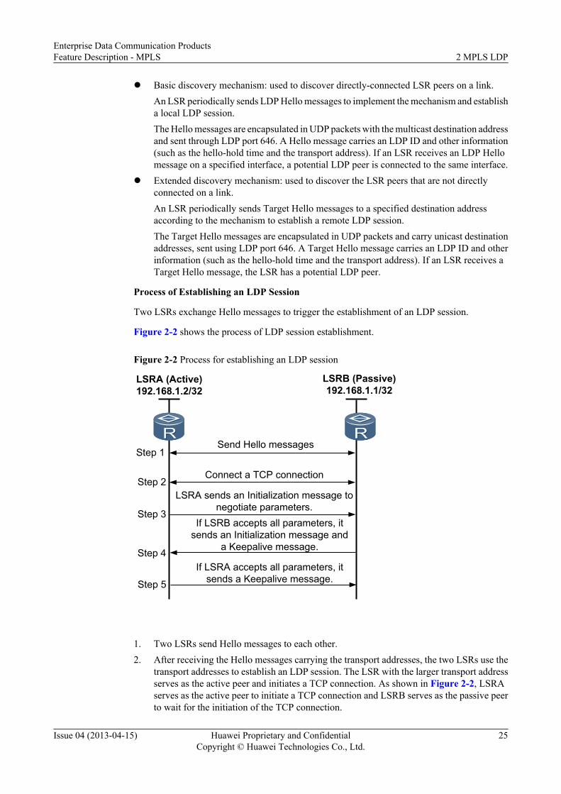
Process of Establishing an LDP Session
Two LSRs exchange Hello messages to trigger the establishment of an LDP session.
Figure 2-2 shows the process of LDP session establishment.
Figure 2-2 Process for establishing an LDP session
LSRB (Passive)192.168.1.1/32
LSRA (Active)192.168.1.2/32
Send Hello messages
LSRA sends an Initialization message to negotiate parameters.
If LSRB accepts all parameters, it sends an Initialization message and
a Keepalive message.
If LSRA accepts all parameters, it sends a Keepalive message.
Step 1
Step 2
Step 3
Step 4
Step 5
Connect a TCP connection
1. Two LSRs send Hello messages to each other.2. After receiving the Hello messages carrying the transport addresses, the two LSRs use the
transport addresses to establish an LDP session. The LSR with the larger transport addressserves as the active peer and initiates a TCP connection. As shown in Figure 2-2, LSRAserves as the active peer to initiate a TCP connection and LSRB serves as the passive peerto wait for the initiation of the TCP connection.
Enterprise Data Communication ProductsFeature Description - MPLS 2 MPLS LDP
Issue 04 (2013-04-15) Huawei Proprietary and ConfidentialCopyright © Huawei Technologies Co., Ltd.
25

3. After the TCP connection is successfully established, LSRA sends an Initialization messageto negotiate parameters used to establish an LDP session with LSRB. The main parametersinclude the LDP version, label advertisement mode, the Keepalive hold timer value,maximum PDU length, and label space.
4. If LSRB rejects some parameters, it sends a Notification message to terminate theestablishment of the LDP session. If LSRB accepts all parameters, it sends an Initializationmessage carrying the LDP version, label advertisement mode, the Keepalive hold timervalue, maximum PDU length, and label space, and sends a Keepalive message to LSRA.
5. If LSRA rejects certain parameters after receiving the Initialization message, it sends aNotification message to terminate LDP session establishment. If LSRA accepts allparameters, it sends a Keepalive message to LSRB.
After both LSRA and LSRB have accepted Keepalive messages from each other, the LDP sessionis successfully established.
Advertising and Managing LabelsLabel Advertisement Modes
An LSR on an MPLS network assigns a label to a specified FEC and notifies its upstream LSRsof the label. This means that the label is specified by a downstream LSR, and is distributed fromdownstream to upstream.
As described in Table 2-1, two label advertisement modes are available.
Table 2-1 Label advertisement modes
Label AdvertisementModes
Definition Description
Downstream Unsolicited(DU) mode
An LSR distributes labels toa specified FEC withouthaving to receive LabelRequest messages from itsupstream LSR.
As shown in Figure 2-3, thedownstream egress triggersthe establishment of an LSPdestined for the FEC192.168.1.1/32 using a hostroute and sends a LabelMapping message to theupstream transit node toadvertise the label of the hostroute to 192.168.1.1/32.
Downstream on Demand(DoD) mode
An LSR distributes labels toa specified FEC only afterreceiving Label Requestmessages from its upstreamLSR.
As shown in Figure 2-3, thedownstream egress triggersthe establishment of an LSPdestined for the FEC192.168.1.1/32 in host mode.The upstream ingress sends aLabel Request message to thedownstream egress. Afterreceiving the message, thedownstream egress sends aLabel Mapping message tothe upstream LSR.
Enterprise Data Communication ProductsFeature Description - MPLS 2 MPLS LDP
Issue 04 (2013-04-15) Huawei Proprietary and ConfidentialCopyright © Huawei Technologies Co., Ltd.
26

The label advertisement modes on upstream and downstream LSRs must be the same.
NOTE
When DU is used, LDP supports label distribution for all peers by default. Each node can send LabelMapping messages to all peers without distinguishing upstream and downstream nodes. If an LSRdistributes labels only for upstream peers when it sends Label Mapping messages, the LSR checks theupstream/downstream relationship of the session in routing information. An upstream node cannot sendLabel Mapping messages to its downstream node along a route. If the route changes and the upstream/downstream relationship is switched, the new downstream node resends Label Mapping messages. In thisprocess, the convergence is slow.
Figure 2-3 DU and DoD
Ingress Transit Egress
192.168.1.1/32
Allocate labels to the upstream node
Allocate labels to the upstream node
Request a label from the downstream node
Request a label from the downstream node
Send a label upon receiving the request
DU
DODSend a label upon
receiving the request
Label Distribution Control Modes
The label distribution control mode refers to a method of label distribution on the LSR duringLSP establishment.
As described in Table 2-2, two label distribution control modes are available.
Enterprise Data Communication ProductsFeature Description - MPLS 2 MPLS LDP
Issue 04 (2013-04-15) Huawei Proprietary and ConfidentialCopyright © Huawei Technologies Co., Ltd.
27
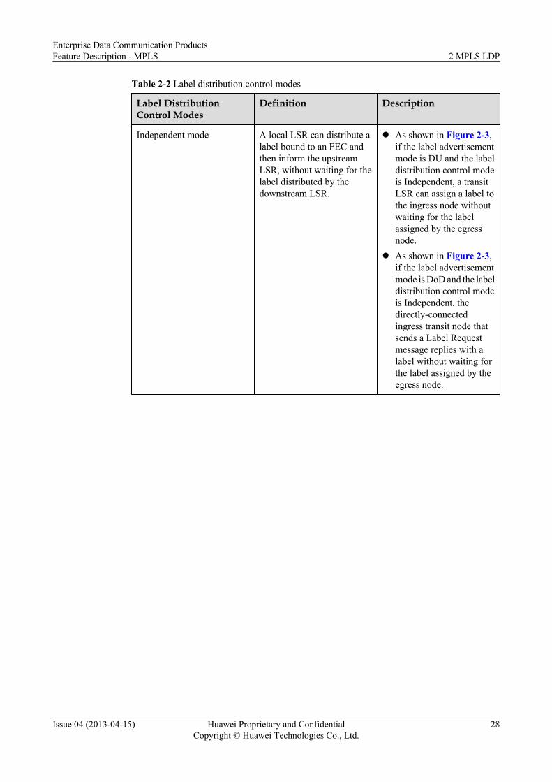
Table 2-2 Label distribution control modes
Label DistributionControl Modes
Definition Description
Independent mode A local LSR can distribute alabel bound to an FEC andthen inform the upstreamLSR, without waiting for thelabel distributed by thedownstream LSR.
l As shown in Figure 2-3,if the label advertisementmode is DU and the labeldistribution control modeis Independent, a transitLSR can assign a label tothe ingress node withoutwaiting for the labelassigned by the egressnode.
l As shown in Figure 2-3,if the label advertisementmode is DoD and the labeldistribution control modeis Independent, thedirectly-connectedingress transit node thatsends a Label Requestmessage replies with alabel without waiting forthe label assigned by theegress node.
Enterprise Data Communication ProductsFeature Description - MPLS 2 MPLS LDP
Issue 04 (2013-04-15) Huawei Proprietary and ConfidentialCopyright © Huawei Technologies Co., Ltd.
28

Label DistributionControl Modes
Definition Description
Ordered mode An LSR advertises themapping between a label andan FEC to its upstream LSRonly when this LSR is theoutgoing node of the FEC orreceives the Label Mappingmessage of the next hop forthe FEC.
l As shown in Figure 2-3,the label distributionmode is DU and the labeldistribution control modeis ordered. Consequently,the LSR (the transit LSRin the diagram) mustreceive a Label Mappingmessage from thedownstream LSR (theegress node in thediagram). Then, it candistribute a label to theingress node in thediagram.
l As shown in Figure 2-3,if the label distributionmode is DoD and the labeldistribution control modeis Ordered, the directly-connected transit of theingress node that sendsthe Label Requestmessage must receive aLabel Mapping messagefrom the downstream (theegress node in thediagram). Then, it candistribute a label to theingress node in thediagram.
Label Retention Modes
The label retention mode refers to the way an LSR processes the label mapping that it receivesbut does not immediately use.
The label mapping that an LSR receives may or may not originate at the next hop.
As described in Table 2-3, two label retention modes are available.
Enterprise Data Communication ProductsFeature Description - MPLS 2 MPLS LDP
Issue 04 (2013-04-15) Huawei Proprietary and ConfidentialCopyright © Huawei Technologies Co., Ltd.
29
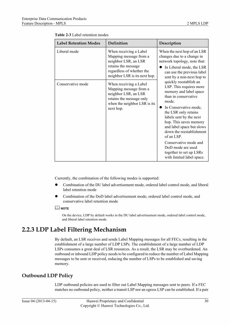
Table 2-3 Label retention modes
Label Retention Modes Definition Description
Liberal mode When receiving a LabelMapping message from aneighbor LSR, an LSRretains the messageregardless of whether theneighbor LSR is its next hop.
When the next hop of an LSRchanges due to a change innetwork topology, note that:l In Liberal mode, the LSR
can use the previous labelsent by a non-next hop toquickly reestablish anLSP. This requires morememory and label spacethan in conservativemode.
l In Conservative mode,the LSR only retainslabels sent by the nexthop. This saves memoryand label space but slowsdown the reestablishmentof an LSP.Conservative mode andDoD mode are usedtogether to set up LSRswith limited label space.
Conservative mode When receiving a LabelMapping message from aneighbor LSR, an LSRretains the message onlywhen the neighbor LSR is itsnext hop.
Currently, the combination of the following modes is supported:
l Combination of the DU label advertisement mode, ordered label control mode, and liberallabel retention mode
l Combination of the DoD label advertisement mode, ordered label control mode, andconservative label retention mode
NOTE
On the device, LDP by default works in the DU label advertisement mode, ordered label control mode,and liberal label retention mode.
2.2.3 LDP Label Filtering MechanismBy default, an LSR receives and sends Label Mapping messages for all FECs, resulting in theestablishment of a large number of LDP LSPs. The establishment of a large number of LDPLSPs consumes a great deal of LSR resources. As a result, the LSR may be overburdened. Anoutbound or inbound LDP policy needs to be configured to reduce the number of Label Mappingmessages to be sent or received, reducing the number of LSPs to be established and savingmemory.
Outbound LDP Policy
LDP outbound policies are used to filter out Label Mapping messages sent to peers. If a FECmatches no outbound policy, neither a transit LSP nor an egress LSP can be established. If a pair
Enterprise Data Communication ProductsFeature Description - MPLS 2 MPLS LDP
Issue 04 (2013-04-15) Huawei Proprietary and ConfidentialCopyright © Huawei Technologies Co., Ltd.
30

of or all peers have the same restriction on the FEC range when sending Label Mappingmessages, the same outbound policy can be configured for the pair of or all peers.
An LDP outbound policy filters out Label Mapping messages only for the FEC, but not thosefor L2VPN. Meanwhile, the LDP outbound policy specifies the FEC range.
In addition, the outbound LDP policy supports split horizon. After split horizon is configured,an LSR distributes labels only to its upstream LDP peers.
Before sending Label Mapping messages only for the FEC to a peer, an LSR checks whether anoutbound policy is configured.l If no outbound policy is configured, the LSR sends the Label Mapping message.l If an outbound policy is configured, the LSR checks whether the FEC in the Label Mapping
message is within the range defined in the outbound policy. If the FEC is within the FECrange, the LSR sends a Label Mapping message for the FEC; if the FEC is not within theFEC range, the LSR does not send a Label Mapping message.
Inbound LDP PolicyLDP inbound policies are used to filter out Label Mapping messages received from peers. If aFEC matches no inbound policy, Label Mapping messages are not accepted. If a pair of or allpeers have the same restriction on the FEC range when receiving Label Mapping messages, thesame inbound policy can be configured for the pair of or all peers.
An LDP inbound policy filters out Label Mapping messages only for the FEC, but not those forL2VPN. Meanwhile, the LDP inbound policy specifies the FEC range for non-BGP routes.
An LSR checks whether an inbound policy mapped to a FEC is configured before receiving aLabel Mapping message for the FEC.l If no inbound policy is configured, the LSR receives the Label Mapping message.l If an inbound policy is configured, the LSR checks whether the FEC in the Label Mapping
message is within the range defined in the inbound policy. If the FEC is within the FECrange, the LSR receives the Label Mapping message for the FEC; if the FEC is not in theFEC range, the LSR does not receive the Label Mapping message.
If the FEC fails to pass an outbound policy on an LSR, the LSR receives no Label Mappingmessage for the FEC.
One of the following results may occur:l If a DU LDP session is established between an LSR and its peer, a liberal LSP is established.
This liberal LSP cannot function as a backup LSP after LDP FRR is enabled.l If a DoD LDP session is established between an LSR and its peer, the LSR sends a Release
message to tear down label-based bindings.
NOTE
An LSP that is distributed with a label but is not successfully established called a liberal LSP.
2.2.4 Synchronization Between LDP and Static RoutesSynchronization between LDP and static routes applies to MPLS networks where primary andbackup LSPs exist. LSPs are established between LSRs based on static routes. When the LDPsession on the primary LSP fails (not due to a link failure) or the primary LSP is restored, MPLStraffic is interrupted for a short time.
Enterprise Data Communication ProductsFeature Description - MPLS 2 MPLS LDP
Issue 04 (2013-04-15) Huawei Proprietary and ConfidentialCopyright © Huawei Technologies Co., Ltd.
31
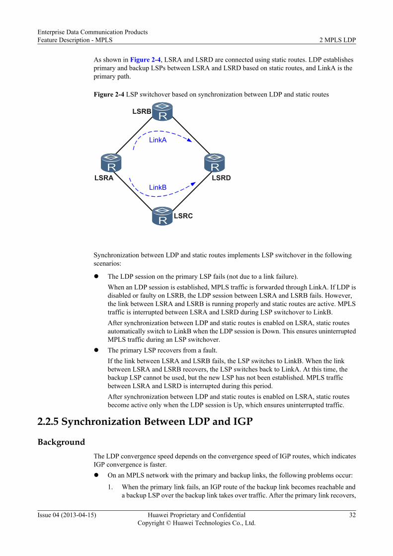
As shown in Figure 2-4, LSRA and LSRD are connected using static routes. LDP establishesprimary and backup LSPs between LSRA and LSRD based on static routes, and LinkA is theprimary path.
Figure 2-4 LSP switchover based on synchronization between LDP and static routes
LSRA LSRD
LSRC
LSRB
LinkA
LinkB
Synchronization between LDP and static routes implements LSP switchover in the followingscenarios:
l The LDP session on the primary LSP fails (not due to a link failure).When an LDP session is established, MPLS traffic is forwarded through LinkA. If LDP isdisabled or faulty on LSRB, the LDP session between LSRA and LSRB fails. However,the link between LSRA and LSRB is running properly and static routes are active. MPLStraffic is interrupted between LSRA and LSRD during LSP switchover to LinkB.After synchronization between LDP and static routes is enabled on LSRA, static routesautomatically switch to LinkB when the LDP session is Down. This ensures uninterruptedMPLS traffic during an LSP switchover.
l The primary LSP recovers from a fault.If the link between LSRA and LSRB fails, the LSP switches to LinkB. When the linkbetween LSRA and LSRB recovers, the LSP switches back to LinkA. At this time, thebackup LSP cannot be used, but the new LSP has not been established. MPLS trafficbetween LSRA and LSRD is interrupted during this period.After synchronization between LDP and static routes is enabled on LSRA, static routesbecome active only when the LDP session is Up, which ensures uninterrupted traffic.
2.2.5 Synchronization Between LDP and IGP
BackgroundThe LDP convergence speed depends on the convergence speed of IGP routes, which indicatesIGP convergence is faster.l On an MPLS network with the primary and backup links, the following problems occur:
1. When the primary link fails, an IGP route of the backup link becomes reachable anda backup LSP over the backup link takes over traffic. After the primary link recovers,
Enterprise Data Communication ProductsFeature Description - MPLS 2 MPLS LDP
Issue 04 (2013-04-15) Huawei Proprietary and ConfidentialCopyright © Huawei Technologies Co., Ltd.
32

the IGP route of the primary link becomes reachable before an LDP session isestablished over the primary link. As a result, traffic is dropped when being transmittedusing the reachable IGP route along the unreachable LSP.
2. When the IGP route of the primary link is reachable and an LDP session betweennodes on the primary link fails, traffic is directed using the IGP route of the primarylink, whereas the LSP over the primary link is torn down. Because a preferred IGProute of the backup link is unavailable, an LSP over the backup link cannot beestablished, causing traffic loss.
l When the active/standby switchover occurs on a node, the LDP session establishment islater than the IGP GR completion. IGP advertises the maximum cost of the link, causingroute flapping.
Related ConceptsSynchronization between LDP and IGP is implemented by suppressing IGP from advertisingnormal routes to ensure convergence performed by synchronization between LDP and IGP.
Synchronization between LDP and IGP involves three timers:l Hold-down timer: used to control the period for establishing the IGP neighbor relationship.l Hold-max-cost timer: used to control the period for advertising the maximum cost of the
link.l Delay timer: used to control the period for waiting for the LSP establishment.
Implementation
Figure 2-5 Synchronization between LDP and IGP for revertive switchover
LSR1 LSR2
LSR3
LSR4
LSR5 LSR6
1
2
The primary LSP recovers from a physical fault.
The IGP status of the primary LSP is normal and the LDP session is faulty.
Primary LSPBackup LSP
l During active/standby link switchover, synchronization between LDP and IGP takes effect.
As shown in Figure 2-5, the processes of synchronization between LDP and IGP differ inthe following scenarios:
1. The primary link recovers from a physical fault.
a. The faulty link recovers.
Enterprise Data Communication ProductsFeature Description - MPLS 2 MPLS LDP
Issue 04 (2013-04-15) Huawei Proprietary and ConfidentialCopyright © Huawei Technologies Co., Ltd.
33

b. An LDP session is set up between LSR2 and LSR3. IGP suppresses theestablishment of the neighbor relationship and starts the Hold-down timer asrequired.
c. Traffic keeps traveling through the LSP over the backup link.d. After the LDP session is set up, Label Mapping messages are exchanged and
then synchronization between IGP and LDP starts.e. The IGP establishes a neighbor relationship and switches traffic back to the
primary link, and the LSP is reestablished and its route converges on the primarylink (in milliseconds).
2. IGP on the primary link is normal and the LDP session is faulty.
a. An LDP session between nodes along the primary link becomes defective.b. LDP notifies the IGP primary link of the session fault. IGP starts the Hold-max-
cost timer and advertises the maximum cost on the primary link.c. The IGP route of the backup link becomes reachable.d. An LSP is established over the backup link and the LDP module on LSR2 delivers
forwarding entries.
The Hold-max-cost timer can be configured to always advertise the maximum cost ofthe primary link. This setting allows traffic to keep traveling through the backup linkbefore the LDP session over the primary link is reestablished.
l During active/standby system switchover, the procedure for synchronization between LDPand IGP is as follows:
1. An IGP on the Restarter advertises a normal cost value and starts a Delay timer, waitingfor an LDP session to be set up. Then IGP ends the GR process.
2. If the Delay timer expires before the LDP session is set up, IGP starts a Hold-max-cost timer, and advertises the maximum cost value of the link.
3. After the LDP session is established or the Hold-max-cost timer expires, IGPadvertises the actual link cost and updates the IGP route.
4. The helper retains the IGP route and LSP. After the LDP session on the helper goesDown, the LDP module does not notify the IGP module of the session status change.This indicates that IGP keeps advertising the actual link cost, preventing traffic or LSPswitchover.
2.2.6 BFD for LSPA Bidirectional Forwarding Detection (BFD) session is established on an LSP. BFD is used toquickly detect faults on the LSP, providing end-to-end protection.
BFD is used to detect faults on the data plane of the MPLS LSP, and the format of BFD packetsis fixed. When a BFD session is associated with a unidirectional LSP, the reverse link can be anIP link, an LSP, or a TE tunnel.
ImplementationBFD detects LSPs in asynchronous mode. The ingress and the egress nodes send BFD controlpackets to each other periodically.
l If any of the ingress and the egress nodes does not receive BFD control packets sent by thepeer within a detection period, LSP status is considered to be Down and a message that theLSP is Down is sent to the LSP Management (LSPM) module.
Enterprise Data Communication ProductsFeature Description - MPLS 2 MPLS LDP
Issue 04 (2013-04-15) Huawei Proprietary and ConfidentialCopyright © Huawei Technologies Co., Ltd.
34

l If the LSP status changes between Up and Down frequently, BFD sends two messages ofLSP changes successively. Therefore, the detection can be performed flexibly.
l If the reverse link of the BFD control packets sent by the egress node to the ingress nodefails, the BFD session is Down.
NOTE
BFD is a bidirectional detection mechanism, but BFD for LSP is unidirectional. BFD for LSP sends BFDcontrol packets through LSPs on the ingress node and through IP links on the egress node. As a result,when the ingress node does not receive BFD control packets sent through the reverse path from the egressnode, the system considers that the LSP fails no matter the fault occurs on LSP or on the reverse link.
BFD Session SetupTo check MPLS LSP connectivity, negotiation on a BFD session can be performed in thefollowing modes:l Static: The negotiation on a BFD session is performed using the local discriminator (LD)
and remote discriminator (RD) that are manually configured.l Dynamic: The negotiation on a BFD session is performed using the BFD discriminator
TLV in an LSP ping packet.
BFD detects the following types of LSPs:l Static BFD for static LSPl Static BFD for LDP LSPl Dynamic BFD for LDP LSP
Figure 2-6 shows the establishment of dynamic BFD sessions that detect LDP LSPs.
1. The ingress node sends an MPLS echo request packet that carries the type-length-value(TLV) with the type as 15 along an LSP. The packet contains an LD that the ingress nodeallocates to the BFD session.
2. The egress node receives the MPLS echo request packet sent from the ingress node andtakes the contained LD as its own RD.
3. The egress node sends an MPLS echo reply packet to the ingress node. The packet containsan LD that the egress node allocates to the BFD session.
4. The ingress node receives the MPLS echo reply packet sent by the egress node and takesthe contained LD as its own RD.The dynamic BFD session that detects the LDP LSP is created successfully.
Enterprise Data Communication ProductsFeature Description - MPLS 2 MPLS LDP
Issue 04 (2013-04-15) Huawei Proprietary and ConfidentialCopyright © Huawei Technologies Co., Ltd.
35

Figure 2-6 Establishing a session of dynamic BFD for LDP LSP
Ingress Egress
Echo request packetIngress LD = 1
Egress RD =Ingress LD = 1
Automatic allocationIngress LD = 1
Echo reply packetEgress LD = 2 Automatic allocation
Egress LD = 2
Ingress RD =Egress LD = 2
2.2.7 LDP FRRLDP Fast Reroute (FRR) provides the fast reroute function for MPLS networks by backing uplocal interfaces.
LDP FRR, in liberal label retention mode of LDP, obtains a liberal label, applies a forwardingentry for the label, and then forwards the forwarding entry to the forwarding plane as the backupforwarding entry for the primary LSP. When the interface is faulty (detected by the interfaceitself or according to BFD detection) or the primary LSP fails (according to BFD detection),LDP FRR fast switches traffic to the backup LSP to protect the primary LSP.
l Manually configured LDP FRR needs to be specified with the outbound interface and nexthop of the backup LSP by running a command. When the source of the liberal label matchesthe outbound interface and next hop, a backup LSP can be established and its forwardingentries can be delivered.
l LDP auto FRR depends on the implementation of IP FRR. When the source of the preservedliberal label matches the outbound interface and next hop of the backup route, therequirement for the policy for establishing the backup LSP is met, and no backup LSPmanually configured according to the backup route exists, a backup LSP can be establishedand its forwarding entries can be delivered. The default policy of LDP auto FRR is thatLDP can use the 32-bit backup routes to establish backup LSPs. When both the manuallyconfigured LDP FRR and LDP auto FRR meet the establishment conditions, the manuallyconfigured LDP FRR is established preferentially.
Enterprise Data Communication ProductsFeature Description - MPLS 2 MPLS LDP
Issue 04 (2013-04-15) Huawei Proprietary and ConfidentialCopyright © Huawei Technologies Co., Ltd.
36

Applicable Environment
Figure 2-7 A typical applicable environment of LDP FRR (triangle topology)
LSRC
LSRA LSRBPrimary LSP
Backup LSP
Figure 2-7 shows a typical applicable environment of LDP FRR. The optimal route from LSRAto LSRB is LSRA -> LSRB and the less optimal route is LSRA -> LSRC -> LSRB. A primaryLSP along the path LSRA -> LSRB is established on LSRA, and a backup LSP along the pathLSRA -> LSRC -> LSRB is established to protect the primary LSP. After receiving a label fromLSRC, LSRA compares the label with the route from LSRA to LSRB and finds that LSRC isnot the next hop of the route. LSRA preserves the label as a liberal label and applies for aforwarding entry as the backup forwarding entry of the primary LSP. LSRA forwards theforwarding entries of both the primary and backup LSPs to the forwarding plane. In this manner,the primary LSP is associated with the backup LSP.
When the interface detects faults by itself, BFD detects faults on the interface, or BFD detectsthat the primary LSP fails, LDP FRR is triggered. After LSP FRR is complete, traffic is switchedto the backup LSP according to the backup forwarding entry. In this manner, LSP FRR takeseffect. Then, the route is converged from LSRA-LSRB to LSRA-LSRC-LSRB. An LSP isestablished on the new LSP (the original backup LSP), and the original primary LSP is deleted,and then the traffic is forwarded along the new LSP LSRA -> LSRC -> LSRB.
Figure 2-8 A typical applicable environment of LDP FRR (rectangle topology)
N1 N2
DSPrimary LSP
Backup LSP
As shown in Figure 2-7, all nodes in the triangle topology supports LDP FRR, but only partsof nodes in the rectangle topology supports LDP FRR. As shown in Figure 2-8, if the optimalroute from N1 to D is N1 -> N2 -> D (load balancing is unavailable), S receives a liberal labelfrom N1 and is configured with LDP FRR. When the link between S and D is faulty, traffic isswitched to the route of S -> N1 -> N2 -> D without forming a loop.
Enterprise Data Communication ProductsFeature Description - MPLS 2 MPLS LDP
Issue 04 (2013-04-15) Huawei Proprietary and ConfidentialCopyright © Huawei Technologies Co., Ltd.
37

However, if the optimal route from N1 to D is load balanced between N1 -> N2 -> D and N1 -> S -> D, S as the downstream neighbor of N1 does not necessarily receive the liberal label fromN1. In addition, even though S receives the liberal label (LDP distributes labels for each peer)and is configured with LDP FRR, traffic may still go to S after traffic switches to N1, whichleads to a loop. This occurs till the route from N1 to D is converged to N1 -> N2 -> D.
2.2.8 LDP GRLDP graceful restart (GR) ensures uninterrupted traffic forwarding on the restarter with the helpof a neighbor (Helper) when an active main board/standby main board (AMB/SMB) switchoveror a protocol restart occurs on the restarter.
When the AMB/SMB switchover occurs on a device that is not capable of GR, the neighbordeletes the LSP because the LDP session becomes Down. As a result, traffic cannot be forwardedand services are interrupted for a short period. To prevent service interruption, LDP GR can beconfigured to keep labels consistent before and after the AMB/SMB switchover or the protocolrestart. LDP GR ensures uninterrupted MPLS forwarding. Figure 2-9 shows the detailedprocess.
1. Before the AMB/SMB switchover, LDP neighbors negotiate the GR capability during theLDP session establishment.
2. After the AMB/SMB switchover, the GR detects helper starts the LDP session failure andstarts the GR Reconnect timer. The GR helper retains the forwarding entries related to theGR restarter and marks the entries with the stale tag.
3. After performing the AMB/SMB switchover, the GR restarter starts the Forwarding StateHolding timer. Before the Forwarding State Holding timer times out, the GR restarterretains all MPLS forwarding entries before the restart and marks the entries with the staletag. The GR restarter then sends an LDP Initialization message to the GR helper. When theForwarding State Holding timer times out, the GR restarter performs step 6.
4. Before the GR Reconnect timer times out, the LDP session is reestablished. The GR helperdeletes the Forwarding State Holding timer, starts the GR Recovery timer, and retains theforwarding entries with the stale tag.
5. Before the GR Recovery timer times out, the neighbors exchange Label Mapping messageswith each other and restore the label binding before the AMB/SMB switchover. When theGR Recovery timer times out, the GR helper deletes all forwarding entries with the staletag.
6. The GR process ends. The GR restarter deletes all forwarding entries with the stale tag.
Enterprise Data Communication ProductsFeature Description - MPLS 2 MPLS LDP
Issue 04 (2013-04-15) Huawei Proprietary and ConfidentialCopyright © Huawei Technologies Co., Ltd.
38

Figure 2-9 LDP GR implementation
GR Restarter GR Helper
AMB/SMB switchover or
protocol restart
Negotiate the GR capability
Exchange the Label Mapping messages
Start the Forwarding State Holding Timer
Label all MPLS forwarding
entries as StaleSend an LDP Initialization message
Reserve forwarding entries labeled Stale
Detects that the LDP session with the GR restarter fails and label forwarding entries related to the GR restarter as Stale
Reconnect the LDP session
Restore the label binding
Disable GR
Restore the label binding
Disable GR
2.2.9 LDP NSRThe non-stop routing (NSR) technology is an innovation based on non-stop forwarding (NSF)technology. If a software or hardware fault occurs on the control plane, NSR ensuresuninterrupted forwarding and connection of the control plane. In addition, the control plane ofa neighbor will not detect any fault.
LDP NSR is implemented using the synchronization of the master and slave control boards.During the startup, the slave control board backs up data of the master control board in batchesto ensure data consistency on both boards. LDP NSR simultaneously notifies the master andslave control boards of receipt of packets and backs up these packets in real time. In this manner,the slave control board synchronizes data with the master control board. NSR ensures that afterswitchover, the slave control board can quickly take over services from the original mastercontrol board, while the neighbor will not detect the fault on the local router.
LDP NSR synchronizes the following key data between the master and slave control boards:l LSP forwarding entriesl Key resources such as labels and cross connectionsl LDP protocol control blocks
2.2.10 LDP Security Mechanisms
MD5 AuthenticationMessage-digest algorithm 5 (MD5) is a standard digest algorithm defined in RFC 1321. A typicalapplication of MD5 is to calculate a message digest to prevent message spoofing. The MD5
Enterprise Data Communication ProductsFeature Description - MPLS 2 MPLS LDP
Issue 04 (2013-04-15) Huawei Proprietary and ConfidentialCopyright © Huawei Technologies Co., Ltd.
39

message digest is a unique result calculated by an irreversible character string conversion. If amessage is modified during transmission, a different digest is generated. After the messagearrives at the receiver, the receiver can determine whether the packet is modified by comparingthe received digest with the pre-calculated digest.
LDP MD5 authentication prevents LDP packets from being modified by generating a uniquedigest for an information segment. This authentication is stricter than the common checksumverification of TCP connections.
Before an LDP message is sent over a TCP connection, LDP MD5 authentication is performedby padding the TCP header with a unique digest. This digest is a result calculated by MD5 basedon the TCP header, LDP session message, and password set by the user.
When receiving this TCP packet, the receiver obtains the TCP header, digest, and LDP sessionmessage, and then uses MD5 to calculate a digest based on the received TCP header, receivedLDP session message, and locally stored password. The receiver compares the calculated digestwith the received one to check whether the packet is modified.
A password can be set in either cipher text or plain text. The plain-text password is directlyrecorded in the configuration file. The cipher-text password is recorded in the configuration fileafter being encrypted using a special algorithm.
During the calculation of a digest, the manually entered character string is used regardless ofwhether the password is in plain text or cipher text. This indicates that a password calculatedusing an encryption algorithm does not participate in MD5 calculation, ensuring that LDP MD5authentication implemented on Huawei devices is transparent to non-Huawei devices.
Keychain AuthenticationKeychain, an enhanced encryption algorithm to MD5, calculates a message digest for the sameLDP message to prevent the message from being modified.
During keychain authentication, a group of passwords are defined to form a password string.Each password is specified with encryption and decryption algorithms such as MD5 algorithmand SHA-1, and is configured with the validity period. When sending or receiving a packet, thesystem selects a valid password based on the user's configuration. Within the valid period of thepassword, the system uses the encryption algorithm matching the password to encrypt the packetbefore sending it out, or uses the decryption algorithm matching the password to decrypt thepacket before accepting it. In addition, the system automatically uses a new password after theprevious password expires, preventing the password from being decrypted.
The keychain authentication password, the encryption and decryption algorithms, and thepassword validity period that construct a keychain configuration node are configured usingdifferent commands. A keychain configuration node requires at least one password andencryption and decryption algorithms.
LDP GTSMGeneralized TTL Security Mechanism (GTSM) is a mechanism that protects the service bychecking whether the TTL value in the IP header is within the pre-defined range. Theprerequisites for using GTSM are as follows:
l The TTL of normal packets between routers is determined.l The TTL value of packets can hardly be modified.
LDP GTSM refers to GTSM implementation over LDP.
Enterprise Data Communication ProductsFeature Description - MPLS 2 MPLS LDP
Issue 04 (2013-04-15) Huawei Proprietary and ConfidentialCopyright © Huawei Technologies Co., Ltd.
40

To protect the router against attacks, GTSM checks the TTL in a packet to verify it. GTSM forLDP is applied to LDP packets between neighbor or adjacent (based on a fixed number of hops)routers. The TTL range is preset on each router for packets from other routers and GTSM isenabled. If the TTL of an LDP packet received by a router configured with LDP is out of theTTL range, the packet is considered invalid and is discarded. This protects the upper-layerprotocols.
2.2.11 LDP Extension for Inter-Area LSPThis feature enables LDP to establish inter-area LDP LSPs to provide tunnels that traverse thepublic network.
Figure 2-10 Networking topology for LDP extension for inter-area LSP
IS-IS Area10
IS-IS Area20
LSRA
LSRB
LSRC
LSRD
Loopback01.1.0.1/32
Loopback01.3.0.1/32
Loopback01.3.0.2/32
Loopback01.2.0.1/32
As shown in Figure 2-10, there are two IGP areas: Area 10 and Area 20.
In the routing table of LSRD at the edge of Area 10, two host routes are reachable to LSRB andLSRC. You can use IS-IS to aggregate the two routes to one route to 1.3.0.0/24 and send thisroute to Area 20 to prevent a large number of routes from occupying too many resources on theLSRD. Consequently, there is only one aggregated route (1.3.0.0/24) but not 32-bit host routesin LSRA's routing table. By default, when establishing LSPs, LDP searches the routing table forthe route that exactly matches the FEC in the received Label Mapping message. Figure 2-10shows routing entry information of LSRA and routing information carried in the FEC, as shownin Table 2-4.
Enterprise Data Communication ProductsFeature Description - MPLS 2 MPLS LDP
Issue 04 (2013-04-15) Huawei Proprietary and ConfidentialCopyright © Huawei Technologies Co., Ltd.
41

Table 2-4 Routing entry information of LSRA and routing information carried in the FEC
Routing Entry Informationof LSRA
FEC
1.3.0.0/24 1.3.0.1/32
1.3.0.2/32
LDP establishes liberal LSPs, not inter-area LDP LSPs, for aggregated routes. In this situation,LDP cannot provide required backbone network tunnels for VPN services.
Therefore, in the situation shown in Figure 2-10, configure LDP to search for routes accordingto the longest match rule for establishing LSPs. There is already an aggregated route to 1.3.0.0/24in the routing table of LSRA. When LSRA receives a Label Mapping message (such as thecarried FEC is 1.3.0.1/32) from Area 10, LSRA searches for a route according to the longestmatch rule defined in RFC 5283. Then, LSRA finds information about the aggregated route to1.3.0.0/24, and uses the outbound interface and next hop of this route as those of the route to1.3.0.1/32. In this manner, LDP can establish inter-area LDP LSPs.
2.2.12 LDP over GRE/mGREGRE provides a mechanism to encapsulate packets of a protocol into packets of another protocol.This allows packets to be transmitted over heterogeneous networks. A channel for transmittingheterogeneous packets is called a tunnel.
A GRE tunnel can be established using the following tunnel interfaces:l GRE tunnel interface
A GRE tunnel interface is a point-to-point virtual interface used to encapsulate packets,and has the source address, destination address, tunnel interface IP address, andencapsulation type.
l mGRE tunnel interfaceAn mGRE tunnel interface is a point-to-multipoint virtual interface used in DSVPNapplications, and has the source address, destination address, and tunnel interface IPaddress.The destination IP address of a GRE tunnel interface is manually configured, whereas thedestination IP address of an mGRE tunnel is resolved by the Next Hop Resolution Protocol(NHRP). An mGRE tunnel interface has multiple remote ends because there are multipleGRE tunnels on the interface.
If backbone network devices are not enabled with MPLS or do not support MPLS, LDP LSPscannot be established. As a result, L2VPN or L3VPN services cannot be deployed. LDP overGRE/mGRE addresses the preceding problem.
LDP over GRELDP over GRE technology establishes an LDP LSP on a GRE tunnel interface configured withMPLS LDP to transmit MPLS LDP packets.
As shown in Figure 2-11, L2VPN or L3VPN services are deployed between PE1 and PE2 ofan enterprise. Because backbone network devices may be not enabled with MPLS or do notsupport MPLS, an LDP LSP across a GRE tunnel needs to be set up between PE1 and PE2.
Enterprise Data Communication ProductsFeature Description - MPLS 2 MPLS LDP
Issue 04 (2013-04-15) Huawei Proprietary and ConfidentialCopyright © Huawei Technologies Co., Ltd.
42

Figure 2-11 Deploying LDP over GRE on L2VPN/L3VPN networking (all P devices do notsupport MPLS)
PE1 PE2
L2VPNSite1
L2VPNSite2
L3VPNSite1
L3VPNSite2
GRE Tunnel
P1 P2
IP/MPLS backbone
LDP LSP for L3VPNLDP LSP for L2VPN
CE1 CE2
CE4CE3
As shown in Figure 2-12, backbone network device P2 supports MPLS, whereas P1 does notsupport MPLS. A GRE tunnel can be established between PE1 and P2 so that an LDP LSP isset up across the GRE tunnel.
Figure 2-12 Deploying LDP over GRE on L2VPN/L3VPN networking (some P devices do notsupport MPLS)
PE1 PE2
L2VPNSite1
L2VPNSite2
L3VPNSite1
L3VPNSite2
P1 P2
IP/MPLSbackbone
LDP LSP for L3VPNLDP LSP for L2VPN
CE1 CE2
CE4CE3
GRE Tunnel
LDP over mGREAs shown in Figure 2-13, the IP/MPLS backbone network is established in the enterpriseheadquarters. Enterprise branches in other areas need to connect to the IP/MPLS backbone
Enterprise Data Communication ProductsFeature Description - MPLS 2 MPLS LDP
Issue 04 (2013-04-15) Huawei Proprietary and ConfidentialCopyright © Huawei Technologies Co., Ltd.
43

network through public network devices. If an L3VPN network needs to be established betweenthe enterprise headquarters and branches, LDP over GRE can be used. There are the followingproblems:l Public addresses of branch devices are not fixed.
The branch Spoke uses a dynamically allocated public address. When LDP over GRE isused, GRE cannot be used to establish a GRE tunnel because public addresses of devicesin multiple branches are not fixed. As a result, L3VPN services cannot be deployed.
l There are many branches.When there are many branches, a large number of Spokes exist. If GRE is used to establishGRE tunnels (assume that devices use fixed public addresses), many GRE interfaces needto be created on Hubs. The configuration is complex and maintenance is difficult.
Dynamic Smart Virtual Private Network (DSVPN) technology solves the preceding problem.NHRP solves problems caused by non-fixed public addresses of branch devices and dynamicallyestablishes a tunnel between the headquarters and a branch. mGRE allows multiple GRE tunnelsto be set up on a tunnel interface, simplifying the Hub configuration.Similar to LDP over GRE,LDP over mGRE technology establishes an LDP LSP on an mGRE tunnel interface configuredwith MPLS LDP to transmit MPLS LDP packets.
As shown in Figure 2-13, the enterprise establishes a backbone network. The headquarters Hub-P uses a static address to connect to the public network and branch Spoke-PE uses dynamicaddresses to connect to the public network. The enterprise requires that L3VPN services bedeployed between all PEs. Because branch devices connect to the enterprise IP/MPLS backbonenetwork through the public network and Spoke-PEs' public addresses are not fixed, LDP overmGRE is used to establish LDP LSPs between PEs across GRE tunnels.
Figure 2-13 Deploying LDP over mGRE in Hub-Spoke networking
Spoke-PE2 Spoke-PE3
Site2 Site3
GRE
Tun
nel
Internet
Hub-P1
Site1
PE1
GRE Tunnel
mGREtunnel interface
IP/MPLSbackbone
VPN1
VPN2 VPN1
VPN2
VPN1
VPN2
Enterprise Data Communication ProductsFeature Description - MPLS 2 MPLS LDP
Issue 04 (2013-04-15) Huawei Proprietary and ConfidentialCopyright © Huawei Technologies Co., Ltd.
44

When LDP over mGRE is used to construct an L3VPN network, traffic between branches isforwarded through Hubs.
There is a delay in transmitting traffic of voice services in this case because voice services requirepoint-to-point transmission. DSVPN can be used to dynamically establish a tunnel so thatbranches can directly communicate. In addition to the preceding advantages, DSVPN has thefollowing problems:l During establishment of a tunnel between Spokes, traffic between branches is forwarded
through the Hub. After the tunnel is set up, traffic is switched to the tunnel. In this process,packet mis-sequencing may occur on the receiver.
l A tunnel between branches needs to be dynamically maintained. If the Spoke performanceis low, maintaining a large amount of tunnel information will cause the Spoke to deteriorateand affect services.
In addition, MPLS requires that labels in MPLS packets be swapped on LSPs between ingressand egress nodes. After LDP over mGRE is used, all Spokes are equivalent to PEs on an MPLSnetwork. If Spokes directly communicate with each other (this scenario is not used), each twoSpokes need to establish an LDP and distribute labels. Consequently, label resources of Spokesare insufficient. You can use the Hub to forward traffic between branches (the Hub, similar tothe P on an MPLS network, maintains the LDP neighbor relationship and swaps packet labels).A Spoke only needs to establish one LSP with the Hub so that the Spoke can communicate withother Spokes. Because MPLS label swapping is used, only traffic on the Hub is increased. Hubperformance is less affected.
Although LDP over mGRE does not use DSVPN to establish tunnels between Spokes, it providesthe Spoke-Hub-Spoke path to better transmit traffic between Spokes. LDP over mGRE is oftenused when the MPLS network needs to be extended.
2.3 ReferencesThe following table lists the references.
Document No. Description
RFC3036 LDP Specification
RFC3215 LDP State Machine
RFC5443 LDP IGP Synchronization
RFC3478 Graceful Restart Mechanism for Label DistributionProtocol
RFC1321 The MD5 Message-Digest Algorithm
RFC3037 LDP Applicability
RFC3899 Maximum Transmission Unit Signalling Extensionsfor the Label Distribution Protocol
RFC3270 Multi-Protocol Label Switching (MPLS) Support ofDifferentiated Services
Enterprise Data Communication ProductsFeature Description - MPLS 2 MPLS LDP
Issue 04 (2013-04-15) Huawei Proprietary and ConfidentialCopyright © Huawei Technologies Co., Ltd.
45

3 MPLS TE
About This Chapter
3.1 Introduction to MPLS TE
3.2 Principles
3.3 Applications
3.4 References
Enterprise Data Communication ProductsFeature Description - MPLS 3 MPLS TE
Issue 04 (2013-04-15) Huawei Proprietary and ConfidentialCopyright © Huawei Technologies Co., Ltd.
46

3.1 Introduction to MPLS TE
Definition
Multiprotocol Label Switching (MPLS) traffic engineering (TE) establishes label switched paths(LSPs) satisfying specific constraints and transparently transmits traffic over the LSPs based onlabels.
Purpose
A node on a conventional IP network selects the shortest path as an optimal route, regardless ofother factors, such as bandwidth. The shortest path may be congested with traffic, but otheravailable paths are idle.
Figure 3-1 Conventional routing
R6
R7
R1
R2
R3
R4
R5
80M
40M
Path 1
Path 2
Each link on the network shown in Figure 3-1 has a bandwidth of 100 Mbit/s and the samemetric value. R1 sends R4 traffic at 80 Mbit/s, and R7 sends R4 traffic at 40 Mbit/s. InteriorGateway Protocol (IGP) calculates the shortest path for traffic, such as Path1 and Path2 in Figure3-1. Traffic on this network is forwarded along the path R2→R3→R4. As a result, the path R2→R3→R4 may be congested because of overload, while the path R2→R5→R6→R4 is idle.
Traffic engineering techniques can load balance traffic to the idle paths to prevent trafficcongestion caused by uneven resource allocation.
Conventional TE solutions are as follows:
l AP TE: AP TE controls network traffic by adjusting the metric of a path. This methodeliminates congestion only on some links. Adjusting a metric is difficult on a complexnetwork because a link change affects multiple routes.
l ATM TE: Because existing Interior Gateway Protocols (IGPs) are topology-driven andconsider only network connectivity, they cannot present some dynamic factors such asbandwidth and traffic characteristics. The IP over asynchronous transfer mode (ATM)overlay model can solve this problem. ATM TE directs some traffic to virtual connections(VCs) using the overlay model so that traffic can be properly scheduled and allocated andQoS guarantee is ensured. However, ATM TE has high costs and low extensibility.
Enterprise Data Communication ProductsFeature Description - MPLS 3 MPLS TE
Issue 04 (2013-04-15) Huawei Proprietary and ConfidentialCopyright © Huawei Technologies Co., Ltd.
47

A scalable and simple solution is required to implement TE on a large-scale network. MPLS,an overlay model, allows a virtual topology to be established over a physical topology and mapstraffic to the virtual topology. MPLS can be integrated with TE. MPLS TE is introduced.
MPLS TE can be used on the network shown in Figure 3-1 to address congestion. MPLS TEsets up two LSPs: Path1 with bandwidth of 80 Mbit/s and Path2 with bandwidth of 40 Mbit/s.MPLS TE directs traffic to the two LSPs, preventing congestion.
Figure 3-2 MPLS TE
R6
R7
R1
R2
R3
R4
R5
Path 1
Path 2
Benefits
MPLS TE effectively schedules, allocates, and uses existing network resources to providesufficient bandwidth and support for quality of service (QoS). MPLS TE helps enterprisesminimize expenditures without requiring hardware upgrades. TE is implemented based onMPLS techniques and is easy to deploy and maintain on live networks. MPLS TE supports arange of reliability techniques, which helps backbone networks achieve carrier- and device-classreliability.
3.2 Principles
3.2.1 Basic ConceptsThis section describes the following basic concepts:l LSP Tunnell MPLS TE Tunnell Link Attributesl Tunnel Attributes
LSP Tunnel
After a label is added to a packet on the ingress node of an LSP, the packet is forwarded basedon the label. Traffic forwarding is transparent to intermediate nodes, so an LSP can be consideredas an LSP tunnel.
Enterprise Data Communication ProductsFeature Description - MPLS 3 MPLS TE
Issue 04 (2013-04-15) Huawei Proprietary and ConfidentialCopyright © Huawei Technologies Co., Ltd.
48

MPLS TE Tunnel
Multiple LSPs are bound together to form an MPLS TE tunnel. The MPLS TE tunnel involvesthe following entities:
l Tunnel interface: a P2P virtual interface that encapsulates packets. Similar to a loopbackinterface, a tunnel interface is a logical interface.
l Tunnel ID: a decimal number that identifies an MPLS TE tunnel and facilitates tunnelplanning and management.
l LSP ID: a decimal number that identifies an LSP, which facilitates LSP planning andmanagement.
A primary LSP with an LSP ID 2 is established along the path LSRA -> LSRB -> LSRC ->LSRD -> LSRE on the network shown in Figure 3-3. A backup LSP with an LSP ID 1024 isestablished along the path LSRA -> LSRF -> LSRG -> LSRH -> LSRE. The two LSPs are in atunnel named Tunnel 0/0/0 with a tunnel ID 100.
Figure 3-3 MPLS TE Tunnel and LSPs
Primary LSP
LSRA
LSRB LSRC LSRD
LSRE
LSRF LSRG LSRHBackup LSP
MPLS TE Tunnel
MPLS TE Tunnel:Tunnel Interface = Tunnel 0/0/0Tunnel ID = 100Primary LSP ID = 2Backup LSP ID = 1024
Link Attributes
MPLS TE link attributes describe bandwidth resources, route costs, and link reliability. The linkattributes are as follows:
l Total link bandwidth: is physical link bandwidth.
l Maximum reservable bandwidth: is the maximum bandwidth that a link can reserve for anMPLS TE tunnel to be established. The maximum reservable bandwidth must be lowerthan or equal to the total link bandwidth.
l TE metric: is the TE cost of a link. To better control path calculation for an MPLS TEtunnel, MPLS TE provides the TE metric so that an IGP route can be selected independently.By default, a link uses the IGP metric as the TE metric.
Enterprise Data Communication ProductsFeature Description - MPLS 3 MPLS TE
Issue 04 (2013-04-15) Huawei Proprietary and ConfidentialCopyright © Huawei Technologies Co., Ltd.
49

l SRLG: is a set of links which are likely to fail concurrently when sharing a physical resource(for example, an optical fiber). Links in an SRLG share the same risk of faults. If one linkfails, other links in the SRLG also fail.An SRLG enhances CR-LSP reliability on an MPLS TE network enabled with CR-LSPhot standby or TE FRR. For more information about the SRLG, see SRLG.
l Link administrative group: is also called link color. A link administrative group is a 32-bitvector, with each bit set to a specified value that is associated with a desired meaning. Forexample, a link administrative group attribute can be configured to describe link bandwidth,a performance parameter or a management policy. The policy can be a traffic type (multicastfor example) or a flag indicating that an MPLS TE tunnel passes over the link. The linkadministrative group attribute is used together with affinities to control the paths fortunnels.
Tunnel AttributesLSPs in an MPLS TE tunnel are constraint-based routed LSPs (CR-LSPs). These constraints aretunnel attributes.
Unlike Label Distribution Protocol (LDP) LSPs that are established using routing information,CR-LSPs are established based on bandwidth and path constraints in addition to routinginformation:l Bandwidth constraint: is the tunnel bandwidth.l Path constraint: includes the explicit path, priority and preemption, route pinning, affinity
attribute, and hop limit.
The mechanism for establishing and managing these constraints is called Constraint-basedRouting (CR). The device supports the following CRs:
l Tunnel bandwidththe values are planned based on services that are to pass through a tunnel. The configuredbandwidth is reserved on each node through which a tunnel passes.
l Explicit pathAn explicit path is used to establish a CR-LSP. Nodes to be included or excluded arespecified on this path. Explicit paths are classified into the following types:– Strict explicit path
A strict explicit path includes specified nodes through which a CR-LSP must pass. Thenext hop must be directly connected to the previous hop. By specifying a strict explicitpath, the most accurate path is provided for a CR-LSP.
Figure 3-4 Strict explicit path
Strict explicit path
LSRB LSRD
LSRC LSRE
LSRFLSRA
Explicit path LSRB Strict LSRC Strict LSRE Strict LSRD Strict
Enterprise Data Communication ProductsFeature Description - MPLS 3 MPLS TE
Issue 04 (2013-04-15) Huawei Proprietary and ConfidentialCopyright © Huawei Technologies Co., Ltd.
50

For example, a CR-LSP is set up between LSRA and LSRF on the network shown inFigure 3-4. LSRA is the ingress, and LSRF is the egress. "X Strict" specifies the LSRthat the CR-LSP must travel through. For example, "LSRB Strict" indicates that theCR-LSP must travel through LSRB, and the previous hop of LSRB must be LSRA."LSRC Strict" indicates that the CR-LSP must travel through LSRC, and the previoushop of LSRC must be LSRB. The procedure repeats. A path with each node specifiedis provided for the CR-LSP.
– Loose explicit pathA loose explicit path contains specified nodes through which a CR-LSP must pass. Otherrouters that are not specified can also exist on the CR-LSP.
Figure 3-5 Loose explicit path
Loose explicit path
LSRB LSRD
LSRC LSRE
LSRFLSRA
Explicit path LSRD Loose
For example, a CR-LSP is set up over a loose explicit path between LSRA and LSRFon the network shown in Figure 3-5. LSRA is the ingress, and LSRF is the egress."LSRD Loose" indicates that the CR-LSP must pass through LSRD and LSRD andLSRA may not be directly connected. This means that other LSRs may exist betweenLSRD and LSRA.
l Priorities and preemptionThey are used to allow TE tunnels to be established preferentially to transmit importantservices, preventing random resource competition during tunnel establishment.CR-LSPs use setup and holding priorities to determine whether to preempt resources. Anew CR-LSP and an established CR-LSP compete for resources by comparing the priorities.The new path can succeed in preemption when its setup priority is higher than the holdingpriority of the established path. The priority value ranges from 0 to 7. A smaller valueallows for a higher priority. The setup priority must be lower than or equal to the holdingpriority for a tunnel.If there is no path meeting the bandwidth requirement of a desired CR-LSP, a device cantear down an established CR-LSP and use the bandwidth assigned to that CR-LSP toestablish a desired CR-LSP. This is called preemption. The following preemption modesare supported:– Hard preemption: A CR-LSP with a higher priority can directly preempt resources
assigned to a CR-LSP with a lower priority. Some traffic is dropped on the CR-LSPwith a lower priority during the hard preemption process.
– Soft preemption: The Make-Before-Break mechanism applies. A CR-LSP with ahigher priority has to wait until traffic over a lower-priority CR-LSP switches to another
Enterprise Data Communication ProductsFeature Description - MPLS 3 MPLS TE
Issue 04 (2013-04-15) Huawei Proprietary and ConfidentialCopyright © Huawei Technologies Co., Ltd.
51

CR-LSP before the higher-priority CR-LSP preempts bandwidth assigned to the lower-priority CR-LSP.
The priority and preemption attributes are used in conjunction to determine resourcepreemption among tunnels. If multiple CR-LSPs are to be established, CR-LSPs with highpriorities can be established by preempting resources. If resources (such as bandwidth) areinsufficient, a CR-LSP with a higher setup priority can preempt resources of an establishedCR-LSP with a lower holding priority.As shown in Figure 3-6, there are two TE tunnels on the network. The link bandwidthallocation is shown in Figure 3-6 and the links have the same metric value.– Tunnel 0/0/1: established over the path LSRA -> LSRB -> LSRE. Its bandwidth is 100
Mbit/s, and its setup and holding priority values are 0.– Tunnel 0/0/2: established over the path LSRC -> LSRB -> LSRF. Its bandwidth is 100
Mbit/s, and its setup and holding priority values are 7.
Figure 3-6 Before a link fault occurs
100M
LSRE
100M
100M 100M
1G
1G
LSRA
LSRB
LSRC LSRD
LSRF
Tunnel 0/0/1
Tunnel 0/0/2
1G
Path1
Path2
Path of Tunnel 0/0/2Path of Tunnel 0/0/1
If the link between LSRB and LSRE fails, LSRA recalculates a path LSRA -> LSRB ->LSRF -> LSRE for tunnel 0/0/1. The link between LSRB and LSRF is shared by tunnel0/0/1 and tunnel 0/0/2, but has insufficient bandwidth for these two tunnels. As a result,preemption is triggered, as shown in Figure 3-7.
Enterprise Data Communication ProductsFeature Description - MPLS 3 MPLS TE
Issue 04 (2013-04-15) Huawei Proprietary and ConfidentialCopyright © Huawei Technologies Co., Ltd.
52
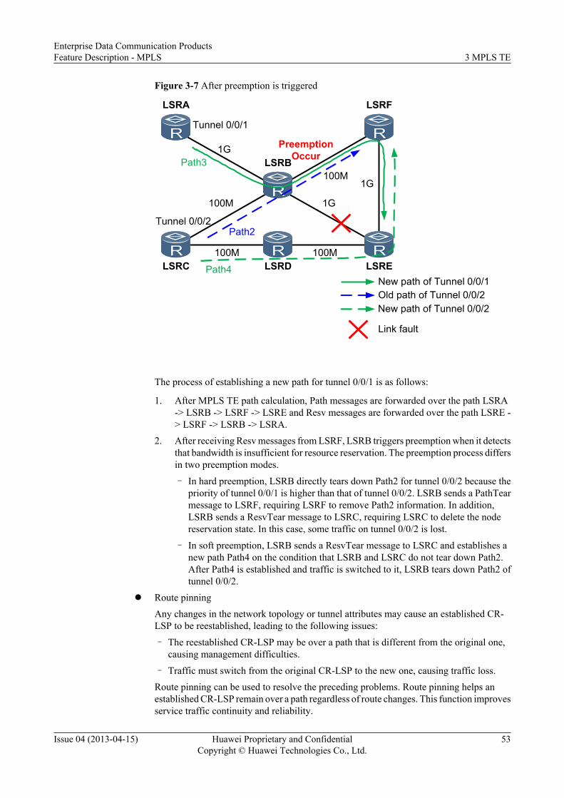
Figure 3-7 After preemption is triggered
100M
LSRE
100M
100M 100M
1G
1G
LSRA
LSRB
LSRC LSRD
LSRF
Tunnel 0/0/1
Tunnel 0/0/2
1G
Path3
Path2
Old path of Tunnel 0/0/2New path of Tunnel 0/0/1
Link fault
PreemptionOccur
Path4
New path of Tunnel 0/0/2
The process of establishing a new path for tunnel 0/0/1 is as follows:
1. After MPLS TE path calculation, Path messages are forwarded over the path LSRA-> LSRB -> LSRF -> LSRE and Resv messages are forwarded over the path LSRE -> LSRF -> LSRB -> LSRA.
2. After receiving Resv messages from LSRF, LSRB triggers preemption when it detectsthat bandwidth is insufficient for resource reservation. The preemption process differsin two preemption modes.
– In hard preemption, LSRB directly tears down Path2 for tunnel 0/0/2 because thepriority of tunnel 0/0/1 is higher than that of tunnel 0/0/2. LSRB sends a PathTearmessage to LSRF, requiring LSRF to remove Path2 information. In addition,LSRB sends a ResvTear message to LSRC, requiring LSRC to delete the nodereservation state. In this case, some traffic on tunnel 0/0/2 is lost.
– In soft preemption, LSRB sends a ResvTear message to LSRC and establishes anew path Path4 on the condition that LSRB and LSRC do not tear down Path2.After Path4 is established and traffic is switched to it, LSRB tears down Path2 oftunnel 0/0/2.
l Route pinningAny changes in the network topology or tunnel attributes may cause an established CR-LSP to be reestablished, leading to the following issues:
– The reestablished CR-LSP may be over a path that is different from the original one,causing management difficulties.
– Traffic must switch from the original CR-LSP to the new one, causing traffic loss.Route pinning can be used to resolve the preceding problems. Route pinning helps anestablished CR-LSP remain over a path regardless of route changes. This function improvesservice traffic continuity and reliability.
Enterprise Data Communication ProductsFeature Description - MPLS 3 MPLS TE
Issue 04 (2013-04-15) Huawei Proprietary and ConfidentialCopyright © Huawei Technologies Co., Ltd.
53

l Affinity attributeAn affinity is a 32-bit vector, configured on the ingress of a tunnel. It must be used togetherwith a link administrative group attribute.After a tunnel is configured with an affinity, a device compares the affinity with theadministrative group value during link selection to determine whether a link with specifiedattributes is selected or not. The device implements two AND operations, one between a32-bit mask and each affinity, and one between the 32-bit mask and the administrativegroup value. If the two AND operations yield the same results, the path is selected. If theresults are different, the path is not selected. The following rules apply:– If some bits in a mask are 1s, at least one bit in the administrative group is 1 and the
corresponding bit in the affinity must be 1. If some bits in the affinity are 0s, thecorresponding bits in the administrative group cannot be 1.For example, an affinity is 0x0000FFFF and its mask is 0xFFFFFFFF. The higher-order16 bits in the administrative group of available links are 0 and at least one of the lower-order 16 bits is 1. This means the administrative group attribute ranges from 0x00000001to 0x0000FFFF.
– If some bits in a mask are 0s, the corresponding bits in the administrative group are notcompared with the affinity bits.For example, an affinity is 0xFFFFFFFF and its mask is 0xFFFF0000. At least one ofthe higher-order 16 bits in an administrative group attribute is 1 and the lower-order 16bits can be 0s and 1s. This means that the administrative group attribute ranges from0x00010000 to 0xFFFFFFFF.
NOTE
Understand specific comparison rules before deploying devices of different vendors because thecomparison rules vary with the vendor.
A network administrator can use the link administrative group and affinities to control thepaths over which MPLS TE tunnels are established.
l Hop limitHop limit is a condition for path selection during CR-LSP establishment. Similar to theadministrative group and affinity attributes, a hop limit defines the number of hops that aCR-LSP allows.
3.2.2 ImplementationFigure 3-8 shows the MPLS TE implementation framework.
Enterprise Data Communication ProductsFeature Description - MPLS 3 MPLS TE
Issue 04 (2013-04-15) Huawei Proprietary and ConfidentialCopyright © Huawei Technologies Co., Ltd.
54

Figure 3-8 MPLS TE implementation framework
Traffic forwarding
Incoming packets
Outgoing packets
IS-IS/OSPF routing
Information advertisement
IGP route selection
LSDB
LSP route selection
TEDB Signaling protocol
Path establishment
Upstream nodes
Downstream nodesLocal nodes
Protocol packet exchanging
Data packet forwarding
Internal information processsing
Path establishment
Information advertisement
Information advertisement, path calculation, path establishment, and traffic forwarding are usedfor establishing an MPLS TE tunnel. The information advertisement function is used to collectTE related information using IGP. The path calculation function is used for calculating pathsbased on information collected. The path establishment function establishes paths by exchangingpackets between upstream and downstream nodes using signaling protocols. The trafficforwarding function imports data packets to the MPLS TE tunnel and forwards the packets.Table 3-1 details the functions.
Table 3-1 MPLS TE implementation process
No.
Function Description
1 InformationAdvertisement
Extends an IGP to advertise TE information, in addition to routinginformation. TE information includes the maximum link bandwidth,maximum reservable bandwidth, reserved bandwidth, and link colors.Every node collects TE information about all nodes in a local area andgenerates a traffic engineering database (TEDB).
2 PathCalculation
Runs Constraint Shortest Path First (CSPF) and uses TEDB data tocalculate a path that satisfies specific constraints. CSPF evolves from theShortest Path First (SPF) protocol. CSPF excludes nodes and links thatdo not satisfy specific constraints and uses the same algorithm that SPFsupports to calculate a path.
Enterprise Data Communication ProductsFeature Description - MPLS 3 MPLS TE
Issue 04 (2013-04-15) Huawei Proprietary and ConfidentialCopyright © Huawei Technologies Co., Ltd.
55

No.
Function Description
3 PathEstablishment
Establishes the following types of CR-LSPs:l Static CR-LSP: set up by manually configuring labels and bandwidth,
irrespective of signaling protocols or path calculation.Setting up a static CR-LSP consumes few resources because no MPLScontrol packets are exchanged between two ends of the CR-LSP. Thestatic CR-LSP cannot be adjusted dynamically in a changing networktopology; therefore, the static CR-LSP is not widely used.
l Dynamic CR-LSP: set up using RSVP-TE signaling. RSVP-TEcarries parameters, such as the tunnel bandwidth, explicit path, andaffinities.There is no need to manually configure each hop along a dynamicCR-LSP. Dynamic CR-LSPs apply to large-scale networks.You can use the RSVP authentication mechanism to improvesecurity and reliability during path establishment.
4 TrafficForwarding
Imports traffic to the MPLS TE tunnel and forwards traffic through thetunnel. The first three functions help establish an MPLS TE tunnel. Thisfunction forwards traffic after traffic is imported to the tunnel.
NOTE
l A static CR-LSP is manually established, and there is no need to use the information advertisement orthe path calculation.
l A dynamic CR-LSP is dynamically established by signaling. Therefore, all the preceding functions areused to establish a dynamic CR-LSP.
When deploying MPLS TE on a network, you need to configure link attributes and tunnelattributes to automatically establish an MPLS TE tunnel. After a tunnel is established, traffichas to be imported to it and forwarded through it.
3.2.3 Information AdvertisementMPLS TE uses routing protocols to advertise resource allocation information about each nodeon a network. Each node on an MPLS TE network especially the ingress node of a tunneldetermines the nodes through which a tunnel passes based on advertised information.
Contents to Be AdvertisedThe network resource information to be advertised includes the following items:l Link status information: interface IP addresses, link types, and link metric values, which
are collected by an Interior Gateway Protocol (IGP).l Bandwidth information, such as maximum link bandwidth and maximum reservable
bandwidth.l TE metric: TE link metric, which is the same as the IGP metric by default.l Link administrative group: link color.l Affinity Attributes: color of the link required by TE.
Enterprise Data Communication ProductsFeature Description - MPLS 3 MPLS TE
Issue 04 (2013-04-15) Huawei Proprietary and ConfidentialCopyright © Huawei Technologies Co., Ltd.
56

l SRLG: shared risk link group. It is a constraint for path calculation of a backup path. SRLGhelps prevent backup and primary paths from overlapping over links with the same risklevel.
Advertisement Methods
MPLS TE advertises information using extended link-state-based routing protocols, includingOSPF TE and IS-IS TE. Open Shortest Path First (OSPF) TE and Intermediate System toIntermediate System (IS-IS) TE automatically collect TE information and flood it to MPLS TEnodes.
OSPF TE
Open Shortest Path First (OSPF) is a link-state-based routing protocol and features strongscalability. OSPF defines label state advertisements (LSAs) of Type 1 to Type 5, and Type 7 tocarry the routing information of the intra-area, inter-area, and autonomous system external (AS-external) for route calculation. These LSAs have fixed formats and cannot meet MPLS TErequirements. Therefore, Opaque LSA and TE LSA are introduced.
l Opaque LSA
The Opaque LSA consists of three types of LSAs, that is, Type 9, Type 10, and Type 11.Type 9 Opaque LSA can be flooded only on an interface; Type 10 Opaque LSA can beflooded only within an area; Type 11 Opaque LSA that is similar to Type 5 LSA, can beflooded within the entire AS outside the stub area and the not-so-stubby area (NSSA).
The Opaque LSA has the similar header format as that of other types of LSAs. Thedifference is that the 4-byte Link State ID field is divided into Opaque Type and OpaqueID, as shown in Figure 3-9.
Figure 3-9 Format of the Opaque LSA
0 2315 31LS age Options LS type=9, 10, 11
Advertising RouterLS sequence number
LS checksum Length
Opaque Type Opaque ID
Opaque Information
7
The first byte is Opaque Type that is used to differentiate between application types of thisLSA; the other three bytes are Opaque ID that is used to differentiate LSAs of the sameapplication type. The Opaque LSA of the same type may have 255 types of applications,and each application can have 16777216 LSAs in a flooding scope.
For example, the LSA applied in the OSPF graceful restart (GR) is Type 9 LSA with theapplication type as 3; the LSA applied in TE extensions is Type 10 LSA with the applicationtype as 1.
The LSA carries information in the Opaque Information field. The information format isdefined by the application with different requirements. Usually, the extensible type-length-value (TLV) format is used.
Enterprise Data Communication ProductsFeature Description - MPLS 3 MPLS TE
Issue 04 (2013-04-15) Huawei Proprietary and ConfidentialCopyright © Huawei Technologies Co., Ltd.
57

Figure 3-10 TLV format
0 15 31Type
ValueLength
– Type: indicates the message type.– Length: defines the length of the Value field, in bytes.– Value: indicates the message carried in TLV. It can be a TLV format. The nested TLV
is called sub-TLV.l TE LSA Extensions
The LSA applied in TE extensions is called TE LSA. The TE LSA is Type 10 LSA, withthe application type as 1. Therefore, the TE LSA has the Link State ID in the format of1.x.x.x; however, the flooding scope is restricted to an area.Figure 3-11 shows the typical format of the TE LSA.
Enterprise Data Communication ProductsFeature Description - MPLS 3 MPLS TE
Issue 04 (2013-04-15) Huawei Proprietary and ConfidentialCopyright © Huawei Technologies Co., Ltd.
58

Figure 3-11 TE LSA format
0 2315 31LS age
Opaque IDOptions LS type=10
Advertising RouterLS sequence number
LS checksum length=132
Link IDExternal Route Tag
Local IP Address
Remote IP Address
TE Metric
Maximum Bandwidth
Maximum Reservable Bandwidth
TLV Type=1 TLV length=4Router Address
TLV Type=2 TLV length=100Sub-TLV Type=1 Sub-TLV length=1
Sub-TLV length=4NSub-TLV Type=3
Sub-TLV Type=4 Sub-TLV length=4N
Sub-TLV Type=5 Sub-TLV length=4
Sub-TLV Type=6 Sub-TLV length=4
Sub-TLV Type=7 Sub-TLV length=4
Opq Type=1
Sub-TLV Type=2 Sub-TLV length=4PaddingLink Type=1
Sub-TLV Type=8 Sub-TLV length=32Unreserved Bandwidth-Priority 0Unreserved Bandwidth-Priority 1
...Unreserved Bandwidth-Priority 7
Sub-TLV Type=9 Sub-TLV length=4Administrative Group
The TE LSA uses the TLV format to carry the needed information. At present, two typesof TLVs are defined as follows:
– TLV Type 1Router address TLV: uniquely identifies an MPLS node. In CSPF, this is known as therouter ID.
Enterprise Data Communication ProductsFeature Description - MPLS 3 MPLS TE
Issue 04 (2013-04-15) Huawei Proprietary and ConfidentialCopyright © Huawei Technologies Co., Ltd.
59

– TLV Type 2
Link TLV: carries the attributes of a link enabled with MPLS TE. Table 3-2 shows thesub-TLVs that can be carried in the Link TLV.
Table 3-2 Sub-TLVs that can be carried in the Link TLV
Sub-TLV Description
Type1: Link Type (the length ofthe Value field is 1 byte)
Indicates the link type.l 1: indicates point-to-point links.l 2: indicates multi-access links.There is padding of three bytes after the value fieldof the Type1 sub-TLV.
Type2: Link ID (the length of theValue field is 4 bytes)
Indicates the link ID. It is in the format of an IPaddress.l For a point-to-point link, this field indicates the
OSPF router ID of the neighbor.l For a multi-access link, this field indicates the
interface IP address of the designated router(DR).
Type3: Local IP Address (thelength of the Value field is 4Nbytes)
Indicates the IP address of the local interface. It canbe IP addresses of several local interfaces. Each IPaddress occupies 4 bytes.
Type4: Remote IP Address (thelength of the Value field is 4Nbytes)
Indicates the IP address of the remote interface. Itcan be IP addresses of several remote interfaces.Each IP address occupies 4 bytes.l For a point-to-point link, this field is set as the
remote IP address.l For a multi-access link, this field can be set as
0.0.0.0 or skipped.
Type5: Traffic EngineeringMetric (the length of the Valuefield is 4 bytes)
Indicates the TE metric configured on a TE link.The data format is ULONG.
Type6: Maximum Bandwidth (thelength of the Value field is 4 bytes)
Indicates the maximum bandwidth of a link. Thedata format is 4 bytes in floating point.
Type7: Maximum ReservableBandwidth (the length of theValue field is 4 bytes)
Indicates the maximum reservable bandwidth of alink. The data format is 4 bytes in floating point.
Type8: Unreserved Bandwidth(the length of the Value field is 32bytes)
Indicates reservable bandwidth of eight prioritiesof a link. Each priority is in the format of 4 bytes infloating point.
Type9: Administrative Group (thelength of the Value field is 4 bytes)
Indicates the administrative group attribute.
Enterprise Data Communication ProductsFeature Description - MPLS 3 MPLS TE
Issue 04 (2013-04-15) Huawei Proprietary and ConfidentialCopyright © Huawei Technologies Co., Ltd.
60

If a link is identified as an MPLS TE link, OSPF runs on the link, and OSPF neighbors areestablished; then the TE extensions to OSPF generates a corresponding TE LSA andadvertises it to the area according to this TE link. If other devices in the area also supportTE extensions, a network topology consisting of TE links is generated among these devices.Each device that advertises the TE LSA must have a unique Router Address.The Opaque LSA of Type 10 is advertised within the OSPF area. Therefore, CSPFcalculation is area-based. The inter-area LSPs need to be calculated in segments.
IS-IS TE
IS-IS is a routing protocol based on link status. It can be extended to advertise TE information.
In extended IS-IS, two TLVs are supported:
l Type 135: Wide MetricIS-IS has two metrics:– Narrow metric: 6 bits– Wide metric: 32 bits. This TLV is not used in route calculation. Instead, it is for TE
information transmission only.Narrow metric provides only 64 metric values. So, it cannot meet the requirements of large-scale traffic engineering. Wide metric is introduced to transfer TE information.During the transition from the narrow metric to the wide metric, IS-IS TE must support thefollowing metrics:– Compatible: capable of receiving and sending the packets with the metric types being
narrow or wide– Wide Compatible: capable of receiving the packets with the metric types being narrow
or wide and sending only the packets with the metric types being widel Type 22: IS reachability TLV
The IS reachability TLV is TLV type 22. Figure 3-12 shows the format of the ISreachability TLV.
Figure 3-12 Format of the IS reachability TLV
150 23 31
System ID and pseudonode number ( 7 octets )Link metric ( 3 octets )
Link metric ( continued ) sub-TLV length ( 1 octets )
sub-TLVs ( 0~244 octets)
The IS reachability TLV consisting of:– System ID and pseudo node ID– Default link metric– Length of sub-TLVs– Sub-TLVs with changeable length
Enterprise Data Communication ProductsFeature Description - MPLS 3 MPLS TE
Issue 04 (2013-04-15) Huawei Proprietary and ConfidentialCopyright © Huawei Technologies Co., Ltd.
61

Table 3-3 describes sub-TLVs of different types.
Table 3-3 Sub-TLVs in IS-IS TE
Sub-TLV Description
Type3: Administrative group (4bytes)
Indicates the administrative group attribute. It hasfour bytes in length. Each set bit corresponds to oneadministrative group assigned to the interface.
Type6: IPv4 interface address (4Nbytes)
Indicates the IP address of the local interface. It canbe IP addresses of several local interfaces. Each IPaddress occupies four bytes.
Type8: IPv4 neighbor address (4Nbytes)
Indicates the IP address of the remote interface. Itcan be IP addresses of several remote interfaces.Each IP address occupies four bytes.l For a point-to-point link, this field is set as the
remote IP address.l For a multi-access link, this field is set as
0.0.0.0.
Type9: Maximum link bandwidth(4 bytes)
Indicates the maximum bandwidth of a link.
Type10: Reservable linkbandwidth (4 bytes)
Indicates the maximum reservable bandwidth of alink.
Type11: Unreserved bandwidth(32 bytes)
Indicates reservable bandwidth of eight priorities ofa link.
Type18: TE Default metric (3bytes)
Indicates the TE metric configured on a TE link.
When to Advertise InformationOSPF TE or IS-IS TE floods link information so that each node can save area-wide linkinformation in a traffic engineering database (TEDB). Information flooding is triggered by theestablishment of an MPLS TE tunnel, or one of the following conditions:
l A specific IGP TE flooding interval elapses.l A link is activated or deactivated.l A CR-LSP in an MPLS TE tunnel fails to be established because of insufficient bandwidth.l Link attributes, such as the administrative group attribute or affinity attribute change.l The link bandwidth changes.
When the available bandwidth of an MPLS interface changes, the system automaticallyupdates information in the TEDB and floods it. When a lot of tunnels are to be establishedon a node, the node reserves bandwidth and frequently updates information in the TEDBand floods it. For example, the bandwidth of a link is 100 Mbit/s. If 100 TE tunnels, eachwith bandwidth of 1 Mbit/s, are established, the system floods link information 100 times.To help suppress the frequency at which TEDB information is updated and flooded, theflooding is triggered based on either of the following conditions:
Enterprise Data Communication ProductsFeature Description - MPLS 3 MPLS TE
Issue 04 (2013-04-15) Huawei Proprietary and ConfidentialCopyright © Huawei Technologies Co., Ltd.
62

– The proportion of the bandwidth reserved for an MPLS TE tunnel to the availablebandwidth in the TEDB is greater than or equal to a specific threshold.
– The proportion of the bandwidth released by an MPLS TE tunnel to the availablebandwidth in the TEDB is greater than or equal to a specific threshold.
If either of the preceding conditions is met, an IGP floods link bandwidth information, andthe device updates the TEDB.
For example, the available bandwidth of a link is 100 Mbit/s and 100 TE tunnels, each withbandwidth of 1 Mbit/s, are established over the link. The flooding threshold is 10%. TheFigure 3-13 shows the proportion of the bandwidth reserved for each MPLS TE tunnel tothe available bandwidth in the TEDB.
Bandwidth flooding is not performed when tunnels 1 to 9 are created. After tunnel 10 iscreated, the bandwidth information (10 Mbit/s in total) on tunnels 1 to 10 is flooded. Theavailable bandwidth is 90 Mbit/s. Similarly, no bandwidth information is flooded aftertunnels 11 to 18 are created. After tunnel 19 is created, bandwidth information on tunnels11 to 19 is flooded. The process repeats until tunnel 100 is established.
Figure 3-13 Proportion of the bandwidth reserved for each MPLS TE tunnel to the availablebandwidth in the TEDB
Second floodingAvailable bandwidth
80Mbit/s
First floodingAvailable bandiwdth
90Mbit/s
Original available bandwidth 100Mbit/s
2%3%
4%5%
6%7%
8%9%
10%
1.1%2.2%
3.3%4.4%
5.6%6.7%
7.8%8.9%
1.3%2.5%
3.8%
10%
1%
1 2 3 4 5 6 7 8 9 10 11 12 13 14 15 16 17 18 19 20 21 22......
Results Obtained After Information Advertisement
Every node creates a TEDB in an MPLS TE area after OSPF TE or IS-IS TE floods bandwidthinformation.
After MPLS TE is deployed on a network, related resource information needs to be advertisedto each node. Each node collects information about link constraints and bandwidth usage in thelocal area to form a database covering network link attributes and topology attributes. Thisdatabase is called TE Database (TEDB).
Enterprise Data Communication ProductsFeature Description - MPLS 3 MPLS TE
Issue 04 (2013-04-15) Huawei Proprietary and ConfidentialCopyright © Huawei Technologies Co., Ltd.
63

A node calculates the optimal path to another node in the MPLS TE area based on informationin the TEDB. MPLS TE then establishes a CR-LSP over this optimal path.
The TEDB and IGP link-state data base (LSDB) are independent of each other. Both TEDB andLSDB contain information flooded by IGP, but they have different content and functions. Inaddition to information contained in the LSDB, TEDB contains TE information. An IGP usesinformation in an LSDB to calculate the shortest path, while MPLS TE uses information in aTEDB to calculate the optimal path.
3.2.4 Path CalculationMPLS TE uses constrained shortest path first (CSPF) to calculate the optimal path to a specifiednode. CSPF, which is derived from SPF, is an algorithm that supports constraints.
CSPF FundamentalsCSPF works based on the following parameters:
l Bandwidth of an LSP tunnel to be established, explicit path, setup priority, hold priority,and affinity attribute, which are configured on the ingress node of a tunnel
l Traffic engineering database (TEDB)
NOTE
A TEDB can be generated only after Interior Gateway Protocol (IGP) TE is configured. On an IGP TE-incapable network, CR-LSPs are established based on IGP routes, but not CSPF calculation results.
CSPF Calculation ProcessCSPF checks the constraints for establishing an LSP to exclude the links that do not meet tunnelattribute requirements in the TEDB, and then calculates the shortest path to the destination ofthe tunnel by using SPF.
NOTE
When both OSPF TE and IS-IS TE are configured, CSPF attempts to use the OSPF TEDB to establish apath for a CR-LSP. If a path is successfully calculated using OSPF TEDB information, CSPF completescalculation and does not use the IS-IS TEDB to calculate a path. If path calculation fails, CSPF attemptsto use IS-IS TEDB information to calculate a path.
CSPF can be configured to use the IS-IS TEDB to calculate a CR-LSP path. If path calculation fails, CSPFuses the OSPF TEDB to calculate a path.
CSPF calculates the shortest path to a destination. If there are several shortest paths with thesame metric, CSPF uses a tie-breaking policy to select one of them. The following tie-breakingpolicies for selecting a path are available:
l Most-fill: selects a link with the highest proportion of used bandwidth to the maximumreservable bandwidth, efficiently using bandwidth resources.
l Least-fill: selects a link with the lowest proportion of used bandwidth to the maximumreservable bandwidth, evenly using bandwidth resources among links.
l Random: selects links randomly, allowing LSPs to be established evenly over links,regardless of bandwidth distribution.
When several links have the same proportion of used bandwidth to the maximum reservablebandwidth, the link discovered first is selected, irrespective of whether most-fill or least-fill isconfigured.
Enterprise Data Communication ProductsFeature Description - MPLS 3 MPLS TE
Issue 04 (2013-04-15) Huawei Proprietary and ConfidentialCopyright © Huawei Technologies Co., Ltd.
64
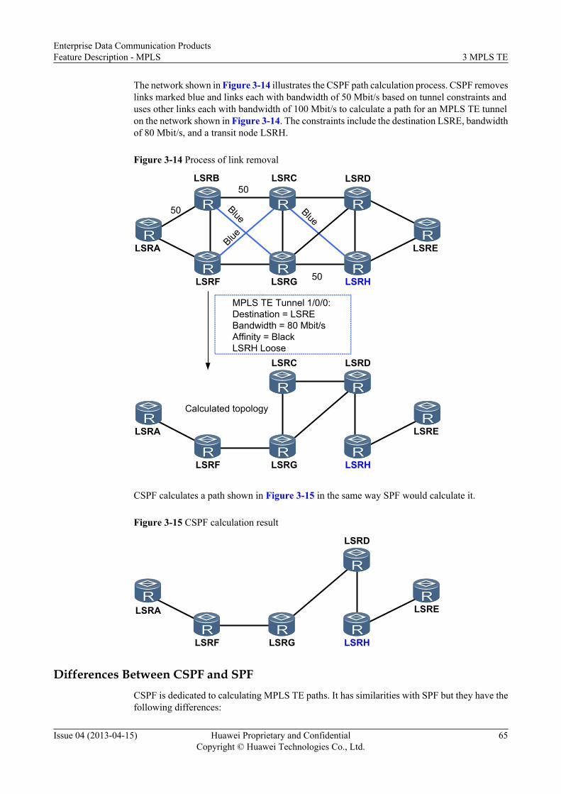
The network shown in Figure 3-14 illustrates the CSPF path calculation process. CSPF removeslinks marked blue and links each with bandwidth of 50 Mbit/s based on tunnel constraints anduses other links each with bandwidth of 100 Mbit/s to calculate a path for an MPLS TE tunnelon the network shown in Figure 3-14. The constraints include the destination LSRE, bandwidthof 80 Mbit/s, and a transit node LSRH.
Figure 3-14 Process of link removal
LSRA
LSRB LSRC LSRD
LSRE
LSRF LSRG LSRH
50
50
50
LSRA
LSRC LSRD
LSRF LSRG LSRH
LSRE
MPLS TE Tunnel 1/0/0:Destination = LSREBandwidth = 80 Mbit/sAffinity = BlackLSRH Loose
Calculated topology
BlueBlue
Blue
CSPF calculates a path shown in Figure 3-15 in the same way SPF would calculate it.
Figure 3-15 CSPF calculation result
LSRD
LSRF LSRG LSRH
LSRELSRA
Differences Between CSPF and SPFCSPF is dedicated to calculating MPLS TE paths. It has similarities with SPF but they have thefollowing differences:
Enterprise Data Communication ProductsFeature Description - MPLS 3 MPLS TE
Issue 04 (2013-04-15) Huawei Proprietary and ConfidentialCopyright © Huawei Technologies Co., Ltd.
65

l CSPF calculates the shortest path between the ingress and egress, and SPF calculates theshortest path between a node and each of other nodes on a network.
l CSPF uses tunnel constraints but not link costs between neighboring nodes as the metric.
l CSPF does not support load balancing and uses three tie-breaking policies to determine apath if multiple paths have the same metric.
3.2.5 Path Establishment
3.2.5.1 Path Establishment Modes
CR-LSP Establishment Modes
A CR-LSP can be established statically or dynamically.
Establishment of a static CR-LSP relies on manual configuration by a network administrator.This section describes how a dynamic CR-LSP is established using the RSVP-TE signalingprotocol.
RSVP-TE Overview
The Resource Reservation Protocol (RSVP) is designed for the integrated service model andused on each node along a path for resource reservation. The bandwidth reservation capabilitymakes it a suitable signaling protocol for establishing an MPLS TE tunnel.
RSVP-TE is an extension of RSVP to meet MPLS TE requirements. RSVP-TE extends RSVPin the following aspects:
l RSVP-TE appends Label Request objects to Path messages to request labels. Resvmessages carry Label objects that are used to allocate labels.
l The extended RSVP messages can carry information about path constraint parameters, inaddition to label binding information.
l RSVP-TE provides the resource reservation function by supporting MPLS TE bandwidthconstraints through the extended objects.
RSVP Messages
RSVP has the following message types:
l Path message: This message is sent from a sender to receivers to collect path informationof the passing nodes.
l Resv message: This message is sent upstream by the receiver hop-by-hop to respond to thePath message, require resource reservation.
l PathErr message: This message is sent upstream by an node to report errors in processingof the Path messages.
l ResvErr message: This message is sent downstream by an node if errors occur during theprocessing of the Resv messages.
l PathTear message: This message is sent to remove path state of the passing nodes.
l ResvTear message: This message is sent to remove resource reservation state on the node.
Enterprise Data Communication ProductsFeature Description - MPLS 3 MPLS TE
Issue 04 (2013-04-15) Huawei Proprietary and ConfidentialCopyright © Huawei Technologies Co., Ltd.
66

l ResvConf message: This message is sent downstream by the sender hop-by-hop to confirmthe resource reservation requests. It is sent only when the Resv message contains theRESV_CONFIRM object.
l Srefresh message: This message refreshes the states of RSVP neighbors.
RSVP-TE PrinciplesTable 3-4 lists RSVP-TE principles.
Table 3-4 RSVP-TE principles
Function Module Description
3.2.5.2Establishment ofDynamic CR-LSPs
A CR-LSP is established over a path calculated by CSPF or anexplicit path on the ingress.
3.2.5.3 Maintenanceof Dynamic CR-LSPs
l Path Status MaintenanceRSVP-TE sends messages to maintain path status on each node.
l Fault AdvertisementRSVP nodes send advertisements to notify upstream anddownstream nodes of faults that occur during path establishmentor maintenance.
l Path TeardownA CR-LSP is torn down and releases labels and bandwidths oneach node. The ingress initiates the request for a teardown.
3.2.5.2 Establishment of Dynamic CR-LSPsTo establish dynamic CR-LSPs, an ingress node sends Path messages to an egress node and theegress node sends Resv messages to the ingress node. Path messages are used to create RSVPsessions and maintain path states, so each node along the path that receives a Path messagecreates a path state block (PSB). Resv messages carry resource reservation information, so eachnode along the path that receives a Resv message creates a reserved state block (RSB) and theallocated label.
Figure 3-16 shows the process of establishing an RSVP-TE CR-LSP.
Figure 3-16 Process of establishing an RSVP-TE CR-LSP
Path Path Path
ResvResv
if1 if0 if1 if0 if1 if0
PE1 P1 P2 PE2Resv
1 2 3
456
1. PE1 uses CSPF to calculate a path between PE1 and PE2. The IP address of every hop onthis path has been specified. PE1 generates a Path message and creates a PSB. PE1 thenadds the explicit route object (ERO) field containing a list of IP addresses calculated by
Enterprise Data Communication ProductsFeature Description - MPLS 3 MPLS TE
Issue 04 (2013-04-15) Huawei Proprietary and ConfidentialCopyright © Huawei Technologies Co., Ltd.
67

CSPF, and sends the Path message to P1 along the path specified by the ERO. Table 3-5lists information carried in a Path message.
Table 3-5 Path message on PE1
Object Value
SESSION Source: PE1-if1; Destination: PE2-if0
RSVP_HOP PE1-if1
EXPLICIT_ROUTE P1-if0; P2-if0; PE2-if0
LABEL LABEL_REQUEST
2. After P1 receives the Path message, P1 parses the message and creates PSB based on the
Path message. P1 then generates a new Path message and sends it to P2 based on the ERO.Table 3-6 lists information carried in a Path message.
l In the previous step, PE1 updates the RSVP_HOP field in the Path message to the IPaddress of the outbound interface when the message is transmitted from PE1 to P1.Similarly, P1 updates the RSVP_HOP field in the Path message to the IP address of theoutbound interface when the message is transmitted from P1 to P2.
l P1 deletes the local LSR ID and IP addresses of the inbound and outbound interfacesfrom the ERO field in the Path message.
Table 3-6 Path message on P1
Object Value
SESSION Source: PE1-if1; Destination: PE2-if0
RSVP_HOP P1-if1
EXPLICIT_ROUTE P2-if0: PE2-if0
LABEL LABEL_REQUEST
3. P2 deals with the received Path message in the same process as that on P1. P2 creates a
PSB based on the Path message, updates the new Path message, and sends it to PE2. Table3-7 lists information carried in a Path message.
Table 3-7 Path message on P2
Object Value
SESSION Source: PE1-if1; Destination: PE2-if0
RSVP_HOP P2-if1
EXPLICIT_ROUTE PE2-if0
LABEL LABEL_REQUEST
Enterprise Data Communication ProductsFeature Description - MPLS 3 MPLS TE
Issue 04 (2013-04-15) Huawei Proprietary and ConfidentialCopyright © Huawei Technologies Co., Ltd.
68

4. After PE2 receives a Path message, PE2 knows that itself is the egress of the CR-LSP tobe set up based on the Tunnel Address field in the Session object. PE2 then allocates a labeland bandwidth resources, and generates an RSB based on the Resv message. The Resvmessage is sent to P2 and carries the label which is allocated by PE2.PE2 extracts an IP address from the RSVP_HOP field of the received Path message anduses it as the destination IP address of the Resv message. The Resv message is forwardedalong the reverse path. Therefore, the Resv message does not carry the ERO field. Table3-8 lists information carried in a Resv message.
NOTE
If the Resv message contains the RESV_CONFIRM object, nodes receiving the Resv message mustsend a ResvConf message to the generator of the Resv message to confirm the request for resourcereservation.
Table 3-8 Resv message on PE2
Object Value
SESSION Source: PE2-if0; Destination: PE1-if1
RSVP_HOP PE2-if0
LABEL 3
RECORD_ROUTE PE2-if0
5. When P2 receives the Resv message, P2 create an RSB based on the Resv message, allocates
a new label, updates the Resv message, and sends the message to P1. Table 3-9 listsinformation carried in a Resv message.
Table 3-9 Resv message on P2
Object Value
SESSION Source: PE2-if0; Destination: PE1-if1
RSVP_HOP P2-if0
LABEL 17
RECORD_ROUTE P2-if0; PE2-if0
6. P1 deals with the received Resv message in the same process as that on P2. P1 updates the
Resv message and sends the message to PE1. Table 3-10 lists information carried in a Resvmessage.PE1 obtains the label allocated by P1 based on the received Resv message. Resourcereservation succeeds and a CR-LSP is set up.
Table 3-10 Resv message on P1
Object Value
SESSION Source: PE2-if0; Destination: PE1-if1
Enterprise Data Communication ProductsFeature Description - MPLS 3 MPLS TE
Issue 04 (2013-04-15) Huawei Proprietary and ConfidentialCopyright © Huawei Technologies Co., Ltd.
69

Object Value
RSVP_HOP P1-if0
LABEL 18
RECORD_ROUTE P1-if0; P2-if0; PE2-if0
3.2.5.3 Maintenance of Dynamic CR-LSPs
Path Status MaintenanceSoft State
Software state indicates that RSVP-TE periodically refreshes RSVP messages to maintain theresource reservation state.
The resource reservation state can be classified into two types: path state and reservation state.Path and Resv messages are created and refreshed periodically to maintain the two statesrespectively. These messages are called RSVP Refresh messages. RSVP Refresh messagescontain PSB and RSB and are used for state synchronization on neighboring RSVP nodes. If anode does not receive any Refresh message about PSB or RSB within a specified time period,the node deletes the path or reservation state.
RSVP Refresh
RSVP messages are transmitted as IP datagrams; therefore the transmission is unreliable. Aftera CR-LSP is established, each node along the established CR-LSP periodically sends RSVPRefresh messages to its upstream and downstream nodes to synchronize states (including PSBand RSB) of neighboring RSVP nodes.
NOTE
A Refresh message is not a new type of message. Refresh messages are the messages that have alreadybeen advertised.
The refreshing interval is specified in the Time Value field.
If the PSB or RSB does not receive any Refresh message about a certain state block after thekeep-multiplier refreshing intervals elapses, it deletes the state. keep-multiplier specifies thenumber of dropped successive RSVP Refresh message on a node. The default keep-multiplieris 3.
Sending of Path and Resv messages between neighboring RSVP nodes is independent to eachother.
RSVP Srefresh
RSVP Refresh messages are used to synchronize path state block (PSB) and reservation stateblock (RSB) information between nodes. They can also be used to monitor the reachabilitybetween RSVP neighbors and maintain RSVP neighbor relationships. As the sizes of Path andResv messages are larger, sending many messages to establish many CR-LSPs causes increasedconsumption of network resources. RSVP Srefresh can be used to address this problem.
RSVP Srefresh defines new objects based on the existing RSVP protocol:l Message_ID extension and retransmission extension
Enterprise Data Communication ProductsFeature Description - MPLS 3 MPLS TE
Issue 04 (2013-04-15) Huawei Proprietary and ConfidentialCopyright © Huawei Technologies Co., Ltd.
70

According to the Message_ID extension mechanism defined in RFC 2961, RSVP messagescarry extended objects, including Message_ID and Message_ID_ACK objects. The twoobjects are used to confirm RSVP messages and support reliable RSVP message delivery.
The Message_ID object can also be used to provide the RSVP retransmission mechanism.For example, a node initializes a retransmission interval as Rf seconds after it sends anRSVP message carrying the Message_ID object. If the node receives no ACK messagewithin Rf seconds, the node retransmits an RSVP message after (1 + Delta) x Rf seconds.The Delta determines the increased rate of the transmission interval set by the sender. Thenode keeps retransmitting the message until it receives an ACK message or theretransmission times reach the threshold (called a retransmission increment value). Bydefault, Rf is set to 500 milliseconds, Delta is set to 1, and the retransmission times is setto 3.
l Summary Refresh extension
The Summary Refresh extension supports Srefresh messages to update the RSVP status,without the transmission of standard Path or Resv messages. The Srefresh extension buildson the Message_ID extension.
Each Srefresh message carries a Message_ID object. Each object contains multiplemessages IDs, each of which identifies a Path or Resv state to be refreshed. If a CR-LSPchanges, its message ID value increases.
Only the state that was previously advertised by Path and Resv messages containingMessage_ID objects can be refreshed using the Srefresh extension.
After a node receives an Srefresh message, the node compares the Message_ID with thatsaved in a local state block. If they match, the node does not change the state. If theMessage_ID is greater than that saved in the local state block, the node sends a NACKmessage to the sender, refreshes the PSB or RSB based on the Path or Resv message, andupdates the Message_ID.
Fault Advertisement
RSVP-TE uses the following messages to advertise LSP errors.
l PathErr message: sent upstream by an RSVP node if an error occurs while this node isprocessing a Path message. A PathErr message is forwarded by consecutive transit nodesand arrives at the ingress.
l ResvErr message: sent downstream by an RSVP node if an error occurs while this node isprocessing a Resv message. A ResvErr message is forwarded by consecutive transit nodesand arrives at the egress.
Path Teardown
After a user instructs an ingress to delete a CR-LSP or the ingress receives a ResvErr message,the ingress sends a PathTear message to a downstream node. The downstream node receives thismessage, tears down the CR-LSP, and replies to the ingress with a ResvTear message.
The functions of PathTear and ResvTear messages are as follows:
l A PathTear message instructs a node to remove saved path information. The PathTearmessage functions in the opposite way to a Path message.
l A ResvTear message instructs a node to remove resource reservation status. The ResvTearmessage functions in the opposite way to a Resv message.
Enterprise Data Communication ProductsFeature Description - MPLS 3 MPLS TE
Issue 04 (2013-04-15) Huawei Proprietary and ConfidentialCopyright © Huawei Technologies Co., Ltd.
71

3.2.5.4 RSVP-TE Message
RSVP-TE messages exchange information between nodes during the MPLS TE implementationprocess.
RSVP Message Format
Each type of RSVP messages contains a common header. The length and types of other fieldsare not fixed. Figure 3-17 shows the format of RSVP messages.
Figure 3-17 RSVP message format
Objects ( Variable )
Length Class_Number C-Type
Object Content (Variable)
Version Flags RSVP ChecksumSend_TTL RSVP Length
Message TypeReserved
0 4 8 16 31
0 16 3124
Format of RSVP messages
Format of Objects
Table 3-11 describes each field in the format.
Table 3-11 Description of fields in RSVP messages
Field Length Description
Version 4 bits Indicates the RSVP version number. Currently, the versionis 1.
Flags 4 bits Indicates the flag bit. Commonly, the value is 0. In RFC2961, it is extended to identify whether Summary RefreshExtension (Srefresh) is supported. If Srefresh is supported,the value of the flag field is 0x01.
MessageType
8 bits Indicates an RSVP message type. For example, 1 representsthe Path message and 2 represents the Resv message.
RSVPChecksum
16 bits Indicates the RSVP checksum. The value 0 indicates that nochecksum was transmitted.
Send_TTL 8 bits Indicates the TTL of the message. When a node receives anRSVP message, it compares the Send_TTL and the TTL inthe IP header to calculate the hops that the message passesin a non-RSVP area.
Reserved 8 bits Indicates that the field is reserved.
Enterprise Data Communication ProductsFeature Description - MPLS 3 MPLS TE
Issue 04 (2013-04-15) Huawei Proprietary and ConfidentialCopyright © Huawei Technologies Co., Ltd.
72

Field Length Description
RSVP Length 16 bits Indicates the total length of the RSVP message, in bytes.
Objects Variable Indicates the object of the RSVP message. Each RSVPmessage contains kinds of objects. The carried objects varywith types of messages.
Length 16 bits Indicates the total length of the object, in bytes. Its value mustbe a multiple of 4, and at least 4.
Class_Number
8 bits Identifies an object class. Each object class has a name, suchas SESSION, SENDER_TEMPLATE, and TIME_VALUE.
C-Type 8 bits Indicates the object type, unique within the Class_Number.The Class-Number and C-Type is used together to define aunique type for each object.
ObjectContent
Variable Indicates contents of objects. The length of this field ischangeable.
NOTE
For details of each type of RSVP messages, refer to RFC 3209 and RFC 2205.
Path Message
In RSVP-TE, a Path message is used to create an RSVP session and maintain a path state. ThePath message is sent from the ingress node to the egress node in the direction of data flows. Oneach node, the path state block (PSB) is created.
NOTE
The source IP address of a Path message is the LSR ID of the ingress node and the destination IP addressis the LSR ID of the egress node.
Table 3-12 lists some objects carried in the Path message.
Table 3-12 Path message objects
MessageObject
Class_Number
C-Type Object Content
SESSION 1 1 Carries RSVP session information,including the destination address, tunnelID, and extend tunnel ID.
RSVP_HOP 3 1 Identifies the IP address and the handle ofthe outgoing interface of the previous hopthat sends the Path message.
TIME_VALUE
5 1 Carries the refreshing interval.
Enterprise Data Communication ProductsFeature Description - MPLS 3 MPLS TE
Issue 04 (2013-04-15) Huawei Proprietary and ConfidentialCopyright © Huawei Technologies Co., Ltd.
73

MessageObject
Class_Number
C-Type Object Content
SENDER_TEMPLATE
11 1 Specifies the sender IP address and LSPID.
SENDER_TSPEC
12 2 Defines traffic characteristics of the dataflow.
LABEL_REQUEST
19 1 Indicates LABEL_REQUEST object,which is carried only in Path messages.
ADSPEC 13 2 Collects actual QoS parameters about thepath, such as estimation of bandwidth ofthe path, minimal path delay, and pathMTU.
EXPLICIT_ROUTE
20 1 ERO, describes information about thepath through which the LSP passes. Theexplicit paths can be strict or loose. Pathmessages are then forwarded along thespecified ERO, without being restrictedby IGP shortest path.
RECORD_ROUTE
21 1 RRO, lists the LSRs that the Path messagepasses when being transmitted. RRO canbe used to collect path information anddiscover route loops. It can also be copiedto the next Path message for implementingRoute Pinning.
SESSION_ATTRIBUTE
207 l 1:LSP_TUNNEL_RA
l 7: LSPTunnel
Specifies the setup priority, hold priority,reservation style, affinity, and otherinformation.
Resv messageAfter receiving a Path message, the egress node reply with Resv messages. The Resv message,carrying resource reservation information, is sent to the previous node hop-by-hop. Each passingnode creates and maintains a reserved state block (RSB) and allocates a label. When the Resvmessage reaches the ingress node, an LSP is set up successfully.
Table 3-13 describes objects carried in the Resv message.
Enterprise Data Communication ProductsFeature Description - MPLS 3 MPLS TE
Issue 04 (2013-04-15) Huawei Proprietary and ConfidentialCopyright © Huawei Technologies Co., Ltd.
74

Table 3-13 Resv message object
MessageObject
Class_Number
C-Type Object Content
INTEGRITY 4 1 Carries cryptographic data to authenticatethe originating node and to verify thecontents of this RSVP message.
SESSION 1 1 Carries RSVP session information,including the destination address, tunnelID, and extend tunnel ID.
RSVP_HOP 3 1 Identifies the IP address and the index ofthe outgoing interface that sends the Resvmessage.
TIME_VALUE
5 1 Carries the refreshing interval. By default,the value is 30 seconds.
STYLE 8 1 Indicates the resource reservation style. Itis specified on the ingress node.
FLOW_SPEC 9 l 1:Reserved(obsolete)flowspecobject
l 2: Inv-servflowspecobject
Specifies the QoS characteristics of thedata flow.
FILTER_SPEC
10 1 Specifies the sender IP address and LSPID of the node that sends the message.
RECORD_ROUTE
21 1 RRO, collects the IP address of theincoming interface, LSR-ID, and the IPaddress of the outgoing interface of thenode along the path.
LABEL 16 1 Indicates the assigned label.
RESV_CONFIRM
15 1 Indicates a confirmation of the resourcereservation is requested when this objectis received. This object carries the IPaddress of the node that requests aconfirmation of the resource reservation.
Reservation Styles
The treatment style of reserving resources for different senders within the same session is calleda reservation style. The following reservation styles are supported:
Enterprise Data Communication ProductsFeature Description - MPLS 3 MPLS TE
Issue 04 (2013-04-15) Huawei Proprietary and ConfidentialCopyright © Huawei Technologies Co., Ltd.
75

l Fixed Filter (FF) style: creates a separate reservation for a tunnel from a particular sender.This sender does not share its resource reservation with other senders. A resourcereservation on the same link is used by a specific CR-LSP.
l Shared Explicit (SE) style: creates a single reservation shared by a set of selected upstreamsenders. The same resource reservation on the same link is shared by different CR-LSPs.
3.2.6 Traffic Forwarding
Importing Traffic to an MPLS TE Tunnel
The traffic forwarding function imports traffic to a tunnel and forwards traffic over the tunnel.Although the information advertisement, path calculation, and path establishment are used toestablish a CR-LSP in an MPLS TE tunnel, a CR-LSP (unlike an LDP LSP) cannot automaticallyimport traffic. The traffic forwarding component must be used to import traffic to the CR-LSPbefore it forwards traffic.
l Static Routes: applies to scenarios with simple network topology or stable networkenvironment.
l Policy-based Routing: applies to scenarios that require load balancing and securitymonitoring.
l Tunnel Policies: applies to scenarios in which TE tunnels need to be established to transmitVPN services.
l Auto Routes: applies to scenarios with complex network topology or unstable networkenvironment.
Static Routes
Using static routes is the simplest method to import traffic to an MPLS TE tunnel. A TE staticroute works in the same way as a common static route and has a TE tunnel interface as anoutbound interface.
Policy-based Routing
The policy-based routing (PBR) allows the system to select routes based on user-definedpolicies, improving security and load balancing traffic. If PBR is enabled on an MPLS network,IP packets are forwarded over specific CR-LSPs based on PBR rules.
MPLS TE PBR is implemented based on a set of matching rules and behaviors. The rules andbehaviors are defined using an apply clause, in which the outbound interface is a specific tunnelinterface. If packets do not match PBR rules, they are properly forwarded using IP; if they matchPBR rules, they are forwarded over specific CR-LSPs.
Tunnel Policies
Generally, VPN traffic is forwarded through an LSP but not an MPLS TE tunnel. To importVPN traffic to the MPLS TE tunnel, you need to configure a tunnel policy. Two tunnel policiesare available.
l Tunnel type prioritizing policy: Such a policy specifies the sequence in which differenttypes of tunnels are selected by the VPN. You can specify the VPN to select the TE tunnelfirst.
Enterprise Data Communication ProductsFeature Description - MPLS 3 MPLS TE
Issue 04 (2013-04-15) Huawei Proprietary and ConfidentialCopyright © Huawei Technologies Co., Ltd.
76

l Tunnel binding policy: This policy binds a TE tunnel to a s specified VPN by binding aspecified destination address to the TE tunnel to provide QoS guarantee.
Auto RoutesAn Interior Gateway Protocol (IGP) uses an auto route related to a CR-LSP in a TE tunnel thatfunctions as a logical link to calculate a path. The tunnel interface is used as an outbound interfacein the auto route. The TE tunnel is considered a P2P link with a specified metric value. Thefollowing auto routes are supported:
l IGP shortcut: A route related to a CR-LSP is not advertised to neighbor nodes, preventingother nodes from using the CR-LSP.
l Forwarding adjacency: A route related to a CR-LSP is advertised to neighbor nodes,allowing these nodes to use the CR-LSP.The forwarding adjacency advertises CR-LSP routes with neighbor IP addresses by sendinglink-state advertisements (LSAs) or IS-IS link state packets (LSPs). Type 10 Opaque LSAscarry the neighbor IP addresses in the Remote IP Address sub-type-length-value (sub-TLV), and LSPs carry the neighbor IP addresses in intermediate system (IS) reachabilityTLV's Remote IP Address sub-TLV.If the forwarding adjacency is used, nodes on both ends of a CR-LSP must be in the samearea.
The following example demonstrates the IGP shortcut and forwarding adjacency.
Figure 3-18 Schematic diagram for IGP shortcut and forwarding adjacency
R7
R8
R1
R2
R3 R4
R5
R6
510
10
10
1010
10
10
Destination Nexthop CostNode Mode
R2 R7 20
Forwarding Adjacency
R5R7R1 30
R2 Tunnel0/0/1 10R7
Tunnel0/0/1R1 20
R2 R4 25
IGP Shortcut
R5R4R1 35
R2 Tunnel0/0/1 10R7
Tunnel0/0/1R1 20
TE Metric=10MPLS TE Tunnel0/0/1
Enterprise Data Communication ProductsFeature Description - MPLS 3 MPLS TE
Issue 04 (2013-04-15) Huawei Proprietary and ConfidentialCopyright © Huawei Technologies Co., Ltd.
77

A CR-LSP over the path R7 → R6 → R2 is established on the network shown in Figure 3-18,and the TE metric values are specified. When finding a route from R5 and R7 to R2 and R1respectively, the result depends on whether the auto route is used.
l The auto route is not used. R5 uses R4 as the next hop in a route to R1 and a route to R2;R7 uses R6 as the next hop in a route to R1 and a route to R2.
l The auto route is used. Either IGP shortcut or forwarding adjacency can be configured:
– The IGP shortcut is used to advertise the route of Tunnel0/0/1. R5 uses R4 as the nexthop in the route to R1 and the route to R2; R7 uses Tunnel0/0/1 as the next hop in theroute to R1 and the route to R2. R7, unlike R5, uses Tunnel0/0/1 in IGP path calculation.
– The forwarding adjacency is used to advertise the route of Tunnel0/0/1. R5 uses R7 asthe next hop in the route to R1 and the route to R2; R7 uses Tunnel0/0/1 as the next hopin the route to R1 and the route to R2. Both R5 and R7 use Tunnel0/0/1 in IGP pathcalculation.
3.2.7 Tunnel Re-optimizationAn MPLS TE tunnel can be automatically reestablished over a new optimal path (if one exists)if topology information is updated.
Background
MPLS TE tunnels are used to optimize traffic distribution over a network. An MPLS TE tunnelis configured using static information, such as a bandwidth setting and a calculated path. Withoutthe optimization function, an MPLS TE tunnel cannot be automatically updated after the servicebandwidth or a tunnel management policy changes. This wastes network resources. MPLS TEtunnels need to be optimized after being established.
Implementation
A specific event that occurs on the ingress can trigger optimization for a CR-LSP bound to anMPLS TE tunnel. The optimization enables the CR-LSP to be reestablished over the optimalpath with the smallest metric.
NOTE
l Re-optimization is disabled by default. If enabled, re-optimization is performed every 3600 secondsby default.
l The fixed filter (FF) reservation style and CR-LSP re-optimization cannot be configured together.
l Re-optimization cannot be performed for a CR-LSP that is established over an explicit path.
Re-optimization is classified into the following modes:
l Automatic re-optimization
When the interval at which a CR-LSP is optimized elapses, Constraint Shortest Path First(CSPF) attempts to calculate a new path. If the calculated path has a metric smaller thanthat of the existing CR-LSP, a new CR-LSP is set up over the new path. After the CR-LSPis successfully set up, the ingress instructs the forwarding plane to switch traffic to the newCR-LSP and tear down the original CR-LSP. Re-optimization is then complete. If the CR-LSP fails to be set up, traffic is still forwarded along the existing CR-LSP.
l Manual re-optimization
A re-optimization command is run in the user view to trigger re-optimization.
Enterprise Data Communication ProductsFeature Description - MPLS 3 MPLS TE
Issue 04 (2013-04-15) Huawei Proprietary and ConfidentialCopyright © Huawei Technologies Co., Ltd.
78

The Make-Before-Break mechanism is used to ensure uninterrupted service transmissionduring the re-optimization process. Traffic must switch to a new CR-LSP before the originalCR-LSP is torn down.
3.2.8 MPLS TE SecurityRSVP authentication verifies digest messages carried in RSVP messages to prevent attacksinitiated by modified or forged messages. Authentication enhancements can also be used toprevent replay attacks and packet mis-sequence. RSVP authentication and its enhancementsimprove MPLS TE security.
Background
RSVP uses raw IP to transmit packets. Raw IP has no security mechanism and is prone to attacks.RSVP authentication can be used to verify packets based on keys to prevent attacks.
Original RSVP authentication, however, cannot prevent replay attacks or the problem ofneighbor relationship termination resulted from RSVP message mis-sequence. The RSVPauthentication enhancements are used to address this problem. The authentication lifetime,handshake, and message window are added as enhanced functions. The authenticationenhancements improve security and RSVP neighborhood authentication in a harsh networkenvironment, such as network congestion.
Related Concepts
l Raw IP: similar to UDP but unreliable. No control is provided for raw IP. Whether raw IPdatagrams reach their destinations is uncertain.
l Spoofing attack: An unauthorized router establishes a neighbor relationship with a localrouter or attacks the local router by generating pseudo RSVP messages to establish an RSVPneighbor relationship. The pseudo RSVP messages can reserve lots of bandwidths.
l Replay attack: A remote router repeatedly sends a large number of packets with a sequencenumber less than the maximum sequence number on a local router. After the local routerreceives such RSVP packets, the local router terminates the RSVP neighbor relationshipwith the remote router and tears down the CR-LSP.
Implementationl Key authentication
RSVP authentication uses keys carried in packets exchanged between RSVP neighboringnodes to verify those packets, preventing spoofing attacks. The same key must beconfigured on two RSVP neighboring nodes before they perform RSVP authentication. Alocal node uses Keyed-Hashing for Message Authentication Message Digest 5 (HMAC-MD5) to calculate a digest for a key, adds this digest as an integrity object into an RSVPmessage, and sends that message to the remote node. After the remote node receives themessage, the node uses the same key and algorithm to calculate a digest and checks whetherthe local digest is the same as the received one. If they match, the remote node accepts themessage. If they do not match, the remote node discards the message.
l Authentication lifetime
Authentication lifetime specifies how long the RSVP neighbor relationship can last. Itprovides the following functions:
Enterprise Data Communication ProductsFeature Description - MPLS 3 MPLS TE
Issue 04 (2013-04-15) Huawei Proprietary and ConfidentialCopyright © Huawei Technologies Co., Ltd.
79

– When no CR-LSP exists between RSVP neighbors, the RSVP adjacency remains untilthe RSVP authentication lifetime expires. The configuration of the RSVP authenticationtime does not affect the status of existing CR-LSPs.
– This function can avoid continuous RSVP authentication. For example, when RSVPauthentication is enabled between RTA and RTB, but the key is damaged because theRSVP messages sent from RTA to RTB are incorrect, RTB receives and discards themessages. This can cause RTA to continuously send RTB the faulty RSVP messagesand RTB to continuously discard these RSVP messages. The authentication relationshipbetween the neighbors, however, cannot be torn down. In this case, the authenticationlifetime needs to be configured. When a neighbor is able to receive a valid RSVPmessage within the lifetime, the RSVP authentication lifetime resets. Otherwise, theauthentication relationship between RSVP neighbors is deleted after the authenticationlifetime expires.
l Handshake mechanism
The handshake mechanism maintains the RSVP authentication status. After RSVPneighboring nodes authenticate each other, they exchanged handshake packets. If theyaccept the packets, they record a successful handshake. If a local node receives a packetwith the sequence number less than the local maximum sequence number, the local nodeprocesses the packet as follows:
– Discards the packet if the packet shows that the handshake mechanism is not enabledon the remote node.
– Discards the packet if the packet shows that the handshake mechanism is enabled onthe remote node and the local node has a record about a successful handshake. If thelocal node does not have a record about a successful handshake, this packet is the firstone arrives at the local node and the local node starts a handshake process.
l Message window
A message window saves sequence numbers of received RSVP messages. The number ofsequence numbers that can be saved ranges from 1 to 64. When the window size is 1, onlythe largest sequence number of RSVP messages from neighbors can be saved. When thewindow size is not 1, multiple sequence numbers of RSVP messages from neighbors canbe saved. For example, a window size is set to 10, and the largest sequence number of areceived RSVP message is 80. The sequence numbers between 71 and 80 can be saved ifthere is no packet mis-sequence. If a packet mis-sequence problem occurs, the local nodearranges the messages and records the 10 largest sequence numbers.
NOTE
By default, the window size is 1. Packet processing in the handshake mechanism is based on theprerequisite that the the window size is 1. A non-1 window-size affects packet processing in thehandshake mechanism.
RSVP Key Management Modes
RSVP keys can be managed in either of the following modes:
l MD5 key
An MD5 key is entered in either ciphertext or plaintext on an RSVP interface or node. AnMD5 key has the following characteristics:
– A key cannot be shared. Each protocol is configured with a separate key.
– An interface or a node is assigned only one key. The key can be reconfigured but cannotbe changed.
Enterprise Data Communication ProductsFeature Description - MPLS 3 MPLS TE
Issue 04 (2013-04-15) Huawei Proprietary and ConfidentialCopyright © Huawei Technologies Co., Ltd.
80

l Keychain key
Keychain is an enhanced encryption algorithm. A group of passwords are defined in theformat of a password string during keychain authentication, and each password is assigneda specified encryption and decryption algorithm and configured with a validity period.When the system sends or receives a packet, the system selects a valid password. Withinthe validity period of the password, the system uses the encryption algorithm matching thepassword to encrypt the packet before sending it out, or uses the decryption algorithmmatching the password to decrypt the packet before accepting it. In addition, the systemautomatically uses a new password after the previous password expires, minimizingpassword decryption risks.
Keychain management has the following characteristics:
– A keychain authentication password and the encryption and decryption algorithms mustbe configured. A password validity period can also be configured.
– Keychain settings can be shared by separate protocols and features and can be manageduniformly.
Keychain can be used on an RSVP interface and node and support HMAC-MD5.
Leveled RSVP Authentication
Leveled RSVP authentication is supported
l Neighbor-oriented authentication
You can configure authentication information, such as authentication keys, based ondifferent neighbor addresses. RSVP then authenticates each neighbor separately.
The following configuration options available:
– The IP address of an interface on an RSVP neighboring node as an RSVP neighboraddress.
– The LSR ID of an RSVP neighboring node is used as an RSVP neighbor address.
l Interface-oriented authentication
Authentication is configured on interfaces, and RSVP authenticates messages based oninbound interfaces.
Neighbor-oriented authentication has a higher priority than interface-oriented authentication. Anode discards messages if neighbor-oriented authentication fails and performs interface-orientedauthentication only if neighbor-oriented authentication is not enabled.
3.2.9 MPLS TE Reliability
3.2.9.1 Reliability Overview
MPLS TE reliability techniques need to prevent or minimize packet loss that occurs in one ofthe following situations:
l If attributes, such as bandwidth, are modified when an MPLS TE tunnel is transmittingservices, the tunnel is reestablished using new attributes, and services switch to the newpath.
l If a node or link fails while an MPLS TE tunnel is transmitting services, a backup CR-LSPis established and takes over traffic.
Enterprise Data Communication ProductsFeature Description - MPLS 3 MPLS TE
Issue 04 (2013-04-15) Huawei Proprietary and ConfidentialCopyright © Huawei Technologies Co., Ltd.
81
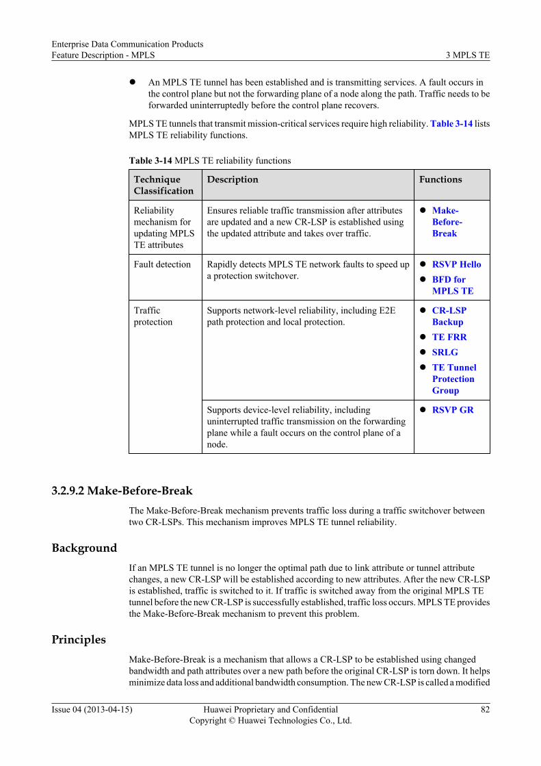
l An MPLS TE tunnel has been established and is transmitting services. A fault occurs inthe control plane but not the forwarding plane of a node along the path. Traffic needs to beforwarded uninterruptedly before the control plane recovers.
MPLS TE tunnels that transmit mission-critical services require high reliability. Table 3-14 listsMPLS TE reliability functions.
Table 3-14 MPLS TE reliability functions
TechniqueClassification
Description Functions
Reliabilitymechanism forupdating MPLSTE attributes
Ensures reliable traffic transmission after attributesare updated and a new CR-LSP is established usingthe updated attribute and takes over traffic.
l Make-Before-Break
Fault detection Rapidly detects MPLS TE network faults to speed upa protection switchover.
l RSVP Hellol BFD for
MPLS TE
Trafficprotection
Supports network-level reliability, including E2Epath protection and local protection.
l CR-LSPBackup
l TE FRRl SRLGl TE Tunnel
ProtectionGroup
Supports device-level reliability, includinguninterrupted traffic transmission on the forwardingplane while a fault occurs on the control plane of anode.
l RSVP GR
3.2.9.2 Make-Before-BreakThe Make-Before-Break mechanism prevents traffic loss during a traffic switchover betweentwo CR-LSPs. This mechanism improves MPLS TE tunnel reliability.
BackgroundIf an MPLS TE tunnel is no longer the optimal path due to link attribute or tunnel attributechanges, a new CR-LSP will be established according to new attributes. After the new CR-LSPis established, traffic is switched to it. If traffic is switched away from the original MPLS TEtunnel before the new CR-LSP is successfully established, traffic loss occurs. MPLS TE providesthe Make-Before-Break mechanism to prevent this problem.
PrinciplesMake-Before-Break is a mechanism that allows a CR-LSP to be established using changedbandwidth and path attributes over a new path before the original CR-LSP is torn down. It helpsminimize data loss and additional bandwidth consumption. The new CR-LSP is called a modified
Enterprise Data Communication ProductsFeature Description - MPLS 3 MPLS TE
Issue 04 (2013-04-15) Huawei Proprietary and ConfidentialCopyright © Huawei Technologies Co., Ltd.
82

CR-LSP. Make-Before-Break is implemented using the shared explicit (SE) resourcereservation style.
The new CR-LSP competes with the original CR-LSP on some shared links for bandwidth. Thenew CR-LSP cannot be established if it fails the competition. The Make-Before-Breakmechanism allows the system to reserve bandwidth used by the original CR-LSP for the newCR-LSP, without calculating the bandwidth to be reserved. Additional bandwidth is used if linkson the new path do not overlap the links on the original path.
Figure 3-19 Schematic diagram for Make-Before-Break
R1 R2 R3 R4
R5
60M 60M 60M
60M
60M
Path1
Path2
In this example, the maximum reservable bandwidth on each link is 60 Mbit/s on the networkshown in Figure 3-19. A CR-LSP along the path Path1 is established, with the bandwidth of 40Mbit/s.
The path is expected to change to Path2 to forward data because R5 has a light load. Thereservable bandwidth of the link between R3 and R4 is just 20 Mbit/s. The total availablebandwidth for the new path is less than 40 Mbit/s. The Make-Before-Break mechanism can beused in this situation. The Make-Before-Break mechanism allows the newly established CR-LSP over the path Path2 to use the bandwidth of the original CR-LSP's link between R3 and R4.After the new CR-LSP is established over the path, traffic switches to the new CR-LSP, and theoriginal CR-LSP is torn down.
In addition to the preceding method, another method of increasing the tunnel bandwidth can beused. If the reservable bandwidth of a shared link increases to a certain extent, a new CR-LSPcan be established.
In the example shown in Figure 3-19, the maximum reservable bandwidth on each link is 60Mbit/s. A CR-LSP along the path Path1 is established, with the bandwidth of 30 Mbit/s.
The path is expected to change to Path2 to forward data because R5 has a light load, and thebandwidth is expected to increase to 40 Mbit/s. The reservable bandwidth of the link betweenR3 and R4 is just 30 Mbit/s. The total available bandwidth for the new path is less than 40 Mbit/s. The Make-Before-Break mechanism can be used in this situation. The Make-Before-Breakmechanism allows the newly established CR-LSP over the path Path2 to use the bandwidth ofthe original CR-LSP's link between R3 and R4. The bandwidth of the new CR-LSP is 40 Mbit/s, out of which 30 Mbit/s is released by the link between R3 and R4. After the new CR-LSP isestablished, traffic switches to the new CR-LSP and the original CR-LSP is torn down.
Delayed Switchover and DeletionIf an upstream node on an MPLS network is busy but its downstream node is idle or an upstreamnode is idle but its downstream node is busy, a CR-LSP may be torn down before the new CR-LSP is established, causing a temporary traffic interruption.
Enterprise Data Communication ProductsFeature Description - MPLS 3 MPLS TE
Issue 04 (2013-04-15) Huawei Proprietary and ConfidentialCopyright © Huawei Technologies Co., Ltd.
83

To prevent this temporary traffic interruption, the switching and deletion delays are used togetherwith the Make-Before-Break mechanism. In this case, traffic switches to a new CR-LSP aspecified delay time later after a new CR-LSP is established. The original CR-LSP is torn downa specified delay later after a new CR-LSP is established. The switching delay and deletion delaycan be manually configured.
3.2.9.3 RSVP Hello
The RSVP Hello extension can rapidly monitor the reachability of RSVP nodes. If an RSVPnode becomes unreachable, TE FRR protection is triggered. The RSVP Hello extension can alsomonitor whether an RSVP GR neighboring node is in the restart process.
Background
RSVP Refresh messages are used to synchronize path state block (PSB) and reservation stateblock (RSB) information between nodes. They can also be used to monitor the reachabilitybetween RSVP neighbors and maintain RSVP neighbor relationships.
Using Path and Resv messages to monitor neighbor reachability delays a traffic switchover if alink fault occurs and therefore is slow. The RSVP Hello extension can address this problem.
Implementation
The principles of the RSVP Hello extension are as follows:
1. Hello handshake mechanism
Figure 3-20 Hello handshake mechanism
LSRA LSRB
Hello Repuest
Hello ACK
LSRA and LSRB are directly connected on the network shown in Figure 3-20.
l If RSVP Hello is enabled on LSRA, LSRA sends a Hello Request message to LSRB.
l After LSRB receives the Hello Request message and is also enabled with RSVP Hello,LSRB sends a Hello ACK message to LSRA.
l After receiving the Hello ACK message, LSRA considers LSRB reachable.
2. Detecting neighbor loss
After a successful Hello handshake is implemented, LSRA and LSRB exchange Hellomessages. If LSRB does not respond to three consecutive Hello Request messages sent byLSRA, LSRA considers router B lost and re-initializes the RSVP Hello process.
3. Detecting neighbor restart
If LSRA and LSRB are enabled with RSVP GR, and the Hello extension detects that LSRBis lost, LSRA waits for LSRB to send a Hello Request message carrying a GR extension.After receiving such a message, LSRA helps LSRB to restore the RSVP state and sends aHello ACK message to LSRB. After receiving the Hello ACK message, LSRB performsthe GR process and restores the RSVP soft state. LSRA and LSRB exchange Hellomessages to maintain the restored RSVP soft state.
Enterprise Data Communication ProductsFeature Description - MPLS 3 MPLS TE
Issue 04 (2013-04-15) Huawei Proprietary and ConfidentialCopyright © Huawei Technologies Co., Ltd.
84

NOTE
On conditions when LSRA and LSRB are on the same CR-LSP:l If GR is disabled and TE FRR is enabled, TE FRR switches traffic to a bypass CR-LSP after the
Hello extension detects that the RSVP neighbor relationship is lost to ensure proper traffictransmission.
l If GR is enabled, the GR process is performed.
Deployment Scenarios
The RSVP Hello extension applies to networks enabled with both RSVP GR and TE FRR.
3.2.9.4 CR-LSP BackupCR-LSP backup techniques protect E2E MPLS TE tunnels. If the ingress detects that the primaryCR-LSP is unavailable, the ingress switches traffic to a backup CR-LSP. After the primary CR-LSP recovers, traffic switches back.
Related ConceptsCR-LSP backup functions include hot standby, ordinary backup, and the best-effort pathfunction.
l Hot-standby: The backup CR-LSP is set up immediately after the primary CR-LSP is setup. If the primary CR-LSP fails, the backup CR-LSP takes over traffic from the primaryCR-LSP.
l Ordinary backup: When the primary CR-LSP fails, the backup CR-LSP is set up and takesover traffic from the primary CR-LSP.
l Best-effort path: The failures of both primary and backup CR-LSPs can trigger the setupof a temporary CR-LSP, which is called the best-effort path. Traffic is then switched to thebest-effort path.For example, the primary CR-LSP is established over the path PE1 → P1 → P2 → PE2,and the backup CR-LSP is established over the path PE1 → P3 → PE2 shown in Figure3-21. If both CR-LSPs fail, PE1 establishes a best-effort path PE1 → P4 → PE2 to takeover traffic.
Figure 3-21 Best-effort path
Primary CR-LSP
Backup CR-LSP
Best-effort path
PE1 PE2
P3
P1 P2
P4
Enterprise Data Communication ProductsFeature Description - MPLS 3 MPLS TE
Issue 04 (2013-04-15) Huawei Proprietary and ConfidentialCopyright © Huawei Technologies Co., Ltd.
85

NOTE
A best-effort path has no bandwidth reserved for traffic, but has an affinity and a hop limit configuredas needed.
ImplementationThe procedure of CR-LSP backup is as follows:
1. Planning is implemented.Plan the paths, bandwidth values, and deployment modes. Table 3-15 lists CR-LSP backupdeployment items.
Table 3-15 CR-LSP backup deployment
Item
Hot Standby Ordinary Backup Best-EffortPath
Path
Determine whether the primaryand hot-standby CR-LSPspartially overlap. A hot-standbyCR-LSP can be established over anexplicit path.
The hot-standby CR-LSP supportsthe following constraints:
l Explicit path
l Affinity
l Hop limit
l Overlapping Path for a Hot-standby CR-LSP
The path of the backupCR-LSP partiallyoverlaps the path of theprimary CR-LSPregardless of whether thebackup CR-LSP is set upalong an explicit path.The ordinary backup CR-LSP supports thefollowing constraints:l Explicit pathl Affinityl Hop limit
Automaticallycalculated bythe ingress.The best-effortpath supportsthe followingconstraints:l Affinityl Hop limit
Bandwidth
A hot-standby CR-LSP and aprimary CR-LSP have the samebandwidth by default. DynamicBandwidth Protection for Hot-standby CR-LSPs is supportedand ensures that a hot-standby CR-LSP does not use additionalbandwidth when transmittingtraffic.
An ordinary backup CR-LSP and a primary CR-LSP have the samebandwidth.
A best-effortpath is only aprotection paththat does nothave reservedbandwidth.
Deploymentmode
Can be established withoutattribute templates.
Can be establishedwithout attributetemplates.
Can beestablishedwithoutattributetemplates.
Enterprise Data Communication ProductsFeature Description - MPLS 3 MPLS TE
Issue 04 (2013-04-15) Huawei Proprietary and ConfidentialCopyright © Huawei Technologies Co., Ltd.
86

Item
Hot Standby Ordinary Backup Best-EffortPath
Can be established using attributetemplates.
Can be established usingattribute templates.
Automaticallyestablished anddoes not supportattributetemplates.
Configurationcombination
l If established without anattribute template, a hot-standby CR-LSP can be usedtogether with a best-effort path.
l If established using an attributetemplate, a hot-standby CR-LSP can be used together withboth an ordinary backup CR-LSP and a best-effort path.
l If established withoutan attribute template,an ordinary CR-LSPcan only be used alone.
l If established using anattribute template, anordinary backup CR-LSP can be usedtogether with a hot-standby backup CR-LSP and a best-effortpath.
-
2. CR-LSPs are established in sequence.
You can establish backup CR-LSPs using different modes on the same tunnel. To quicklyestablish a CR-LSP for service transmission, the system attempts to establish a backup CR-LSP using different modes in sequence until the backup CR-LSP is successfully established.The rules for establishing a CR-LSP are as follows:
a. If new tunnel configuration is committed or a tunnel goes Down, the ingress firstattempts to establish a primary CR-LSP. If the attempt fails, the ingress attempts toestablish a hot-standby CR-LSP. If establishing the hot-standby CR-LSP fails, theingress then attempts to establish an ordinary backup CR-LSP. If this attempt alsofails, the ingress establishes a best-effort path.
b. A maximum of three CR-LSP attribute templates can be configured for hot-standbyCR-LSPs and three for ordinary backup CR-LSPs. These templates are prioritized.The ingress uses each in descending order by priority until a CR-LSP is successfullyestablished.
c. If a CR-LSP has been established using a lower-priority attribute template and theCR-LSP status changes, the ingress will attempt to establish a CR-LSP using a higher-priority attribute template. The Make-Before-Break mechanism ensures that traffic isuninterrupted when a new CR-LSP is being established.
d. If a stable CR-LSP has been established using any of the attribute templates, you canlock the used backup CR-LSP attribute template. After the attribute template is locked,the ingress will not attempt to use a higher-priority attribute template to establish aCR-LSP. This locking function prevents unnecessary traffic switchovers and lowerssystem costs.
3. Backup CR-LSP attributes are modified.When the constraints for backup CR-LSPs are modified, the ingress triggers re-establishment of a backup CR-LSP. The system uses the Make-Before-Break mechanismto re-establish a backup CR-LSP. After that backup CR-LSP has been successfully
Enterprise Data Communication ProductsFeature Description - MPLS 3 MPLS TE
Issue 04 (2013-04-15) Huawei Proprietary and ConfidentialCopyright © Huawei Technologies Co., Ltd.
87

reestablished, traffic on the original backup CR-LSP (if it is transmitting traffic) switchesto this new backup CR-LSP, and the original backup CR-LSP is torn down.
4. Fault detection is implemented.
CR-LSP backup supports the following fault detection functions:
l The RSVP-TE fault advertisement mechanism sends signaling packets to detect faultsat a low speed.
l Bidirectional forwarding detection (BFD) for CR-LSP rapidly detects faults. This is arecommended function.
5. A traffic switchover is implemented.
If a primary CR-LSP fails, the ingress attempts to switch traffic from the primary CR-LSPto a hot-standby CR-LSP. If the hot-standby CR-LSP is unavailable, the ingress attemptsto switch traffic to an ordinary backup CR-LSP. If the ordinary backup CR-LSP isunavailable, the ingress attempts to switch traffic to a best-effort path.
6. A traffic switchback is implemented.
Traffic switches back to a path based on the available CR-LSPs. Traffic will switch first tothe primary CR-LSP, which has the highest priority. If the primary CR-LSP is unavailable,traffic will switch to the hot-standby CR-LSP. The ordinary CR-LSP has the lowest priority.
Dynamic Bandwidth Protection for Hot-standby CR-LSPs
Hot-standby CR-LSPs support dynamic bandwidth protection. The dynamic bandwidthprotection function allows a hot-standby CR-LSP to obtain bandwidth resources only after thehot-standby CR-LSP takes over traffic from a faulty primary CR-LSP. This function usesnetwork resources efficiently and reduces network costs.
Dynamic bandwidth protection ensures that the hot-standby CR-LSP does not use bandwidth,while the primary CR-LSP is transmitting traffic. The dynamic bandwidth protection process isas follows:
1. If the primary CR-LSP fails, traffic immediately switches to the hot-standby CR-LSP with0 bit/s bandwidth. The ingress uses the Make-Before-Break mechanism to establish a hot-standby CR-LSP.
2. After the new hot-standby CR-LSP has been successfully established, the ingress switchestraffic to this CR-LSP and tears down the hot-standby CR-LSP with 0 bit/s bandwidth.
3. After the primary CR-LSP recovers, traffic switches back to the primary CR-LSP. The hot-standby CR-LSP then releases the bandwidth it uses and the ingress establishes anotherhot-standby CR-LSP with no bandwidth.
Overlapping Path for a Hot-standby CR-LSP
The path overlapping function can be configured for hot-standby CR-LSPs. This function allowsthe path of a hot-standby CR-LSP partially overlaps the path of the primary CR-LSP. After thehot-standby CR-LSP is established, it can protect traffic on the primary CR-LSP.
3.2.9.5 TE FRR
TE FRR protects links and nodes on CR-LSPs bound to an MPLS TE tunnel. If a link or nodefails, TE FRR rapidly switches traffic to a backup path, minimizing traffic loss.
Enterprise Data Communication ProductsFeature Description - MPLS 3 MPLS TE
Issue 04 (2013-04-15) Huawei Proprietary and ConfidentialCopyright © Huawei Technologies Co., Ltd.
88

BackgroundA link or node failure triggers a primary/backup CR-LSP switchover. IGP routes of the backuppath need to converge, and CSPF recalculates a path over which a CR-LSP is established. Trafficis dropped during this process.
TE FRR can be used to prevent traffic loss. After a link or node fails, TE FRR establishes abypass CR-LSP, which excludes the faulty link or node. The bypass CR-LSP can rapidly takeover traffic, minimizing traffic loss. The ingress can reestablish a primary CR-LSP.
Related Concepts
Figure 3-22 Local protection
PLR Primary CR-LSP
Bypass CR-LSP
LSRA LSRB LSRC LSRD
LSRE
MP
Table 3-16 describes TE FRR concepts.
Table 3-16 TE FRR concepts
Concept Description
Primary CR-LSP A CR-LSP that is protected.
Bypass CR-LSP A CR-LSP that protects the primary CR-LSP. The bypass CR-LSPis usually in the idle state and transmits few data. If the bypass CR-LSP needs to forward service data when it protects the primary CR-LSP, sufficient bandwidth must be allocated to the bypass CR-LSP.
Point of Local Repair(PLR)
The ingress of the bypass CR-LSP. It must be on the path of theprimary CR-LSP. The PLR can be the ingress, not the egress of theprimary CR-LSP.
Merge point (MP) The egress of the bypass CR-LSP. It must be on the path of theprimary CR-LSP. The MP cannot be the ingress of the primary CR-LSP.
Table 3-16 describes TE FRR protection functions.
Enterprise Data Communication ProductsFeature Description - MPLS 3 MPLS TE
Issue 04 (2013-04-15) Huawei Proprietary and ConfidentialCopyright © Huawei Technologies Co., Ltd.
89

Table 3-17 TE FRR protection functions
ClassifiedBy
Type Description
Objecttobeprotected
Linkprotection
As shown in Figure 3-23, the PLR (LSRB) and MP (LSRC) are directlyconnected, and the primary CR-LSP passes through the direct link. BypassCR-LSP 1 protects the direct link.
Nodeprotection
As shown in Figure 3-23, a primary CR-LSP between the PLR (LSRB)and MP (LSRD) passes through LSRC. Bypass CR-LSP 2 protects LSRCon the primary CR-LSP.
Bandwidth
Bandwidthprotection
The bandwidth of a bypass CR-LSP is higher than or equal to that of theprimary CR-LSP. The bypass CR-LSP protects the primary CR-LSP andits bandwidth.
Non-bandwidthprotection
No bandwidth is assigned to a bypass CR-LSP. The bypass CR-LSPprotects only the path of the primary CR-LSP.
Implementation
Manualprotection
A manually configured bypass CR-LSP is established and bound to a CR-LSP that is to be protected. If a link or node on the protected CR-LSP fails,traffic automatically switches to the bypass CR-LSP.
AutoFRRprotection
An Auto FRR-enabled node automatically establishes a bypass CR-LSP.The node binds the bypass CR-LSP to a primary CR-LSP if the nodereceives an FRR protection request and the FRR topology requirementsare met.
Figure 3-23 TE FRR link and node protection
MP
Primary CR-LSP
LSRA
LSRB LSRC LSRD
LSRE
LSRF LSRG LSRH
PLR
Bypass CR-LSP 1Link protection
Bypass CR-LSP 2 Node protection
Link Fault
MP
Node Fault
Enterprise Data Communication ProductsFeature Description - MPLS 3 MPLS TE
Issue 04 (2013-04-15) Huawei Proprietary and ConfidentialCopyright © Huawei Technologies Co., Ltd.
90

NOTE
A bypass CR-LSP supports the combination of protection types. For example, manual protection, nodeprotection, and bandwidth protection can be implemented together on a bypass CR-LSP.
ImplementationThe PLR implements TE FRR as follows:
1. Establishes a primary CR-LSP.The establishment of a primary CR-LSP is the same as that of a common CR-LSP. Theonly difference is that the tunnel ingress adds SESSION_ATTRIBUTE related flags to thePath message when establishing a primary CR-LSP. For example, a local protection flagindicates a bypass CR-LSP that needs to be bound to the primary CR-LSP. A bandwidthprotection flag indicates that bandwidth protection is required.
2. Binds a bypass CR-LSP to the primary CR-LSP.Searching for a suitable bypass CR-LSP is also called bypass CR-LSP binding. This processis completed before a CR-LSP switchover is performed. A bypass CR-LSP can be boundto a primary CR-LSP only with the local protection flag.Before binding two CR-LSPs, a node must obtain the following information according tothe RRO field in the Resv message. Some of them are listed as follow:l Outbound interfacel Next Hop Label Forwarding Entry (NHLFE)l Label switching router (LSR) ID of the MPl Label allocated by the MPl Protection typeThe PLR node on a primary CR-LSP already obtains information about the next hop(NHOP) or next NHOP (NNHOP). If the egress LSR ID of the bypass CR-LSP is equal tothe LSR ID of the NHOP, link protection is provided. If the egress LSR ID of the bypassCR-LSP is equal to the LSR ID of the NNHOP, node protection is provided. As shown inFigure 3-24, bypass CR-LSP 1 provides link protection and bypass CR-LSP 2 providesnode protection.
Enterprise Data Communication ProductsFeature Description - MPLS 3 MPLS TE
Issue 04 (2013-04-15) Huawei Proprietary and ConfidentialCopyright © Huawei Technologies Co., Ltd.
91
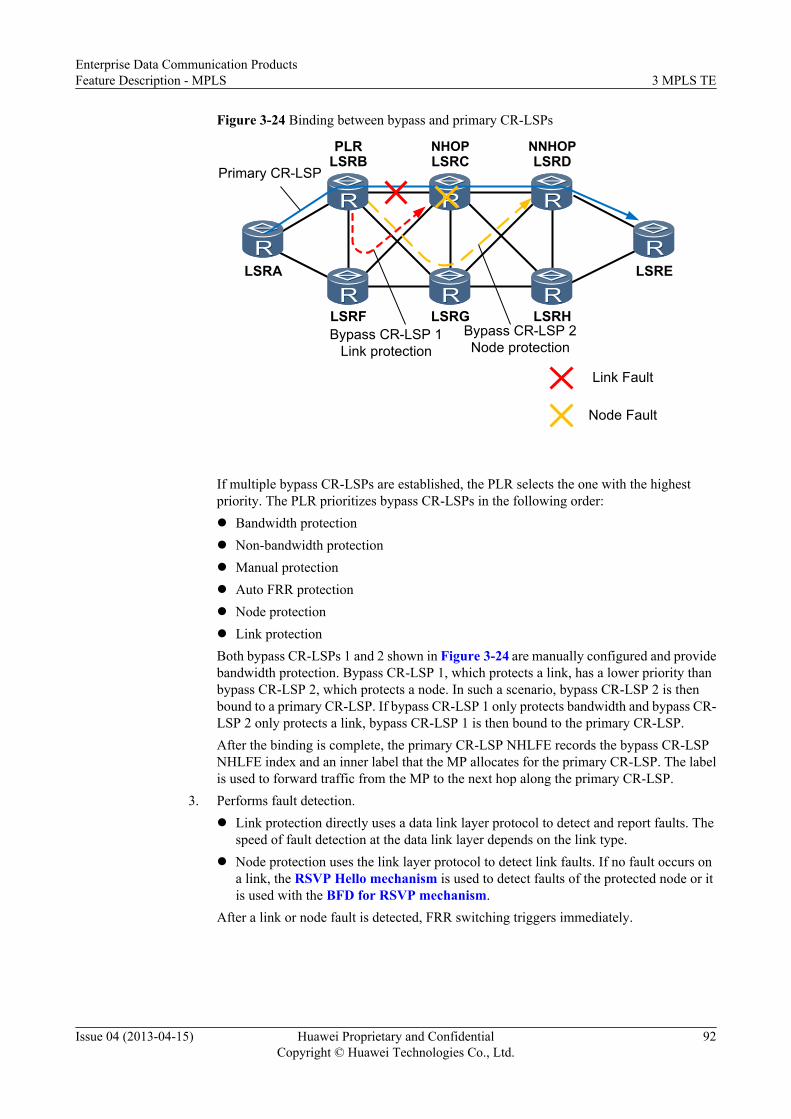
Figure 3-24 Binding between bypass and primary CR-LSPs
Primary CR-LSP
LSRA
LSRB LSRC LSRD
LSRE
LSRF LSRG LSRH
PLR
Bypass CR-LSP 1Link protection
Bypass CR-LSP 2 Node protection
NHOP NNHOP
Link Fault
Node Fault
If multiple bypass CR-LSPs are established, the PLR selects the one with the highestpriority. The PLR prioritizes bypass CR-LSPs in the following order:l Bandwidth protectionl Non-bandwidth protectionl Manual protectionl Auto FRR protectionl Node protectionl Link protectionBoth bypass CR-LSPs 1 and 2 shown in Figure 3-24 are manually configured and providebandwidth protection. Bypass CR-LSP 1, which protects a link, has a lower priority thanbypass CR-LSP 2, which protects a node. In such a scenario, bypass CR-LSP 2 is thenbound to a primary CR-LSP. If bypass CR-LSP 1 only protects bandwidth and bypass CR-LSP 2 only protects a link, bypass CR-LSP 1 is then bound to the primary CR-LSP.After the binding is complete, the primary CR-LSP NHLFE records the bypass CR-LSPNHLFE index and an inner label that the MP allocates for the primary CR-LSP. The labelis used to forward traffic from the MP to the next hop along the primary CR-LSP.
3. Performs fault detection.l Link protection directly uses a data link layer protocol to detect and report faults. The
speed of fault detection at the data link layer depends on the link type.l Node protection uses the link layer protocol to detect link faults. If no fault occurs on
a link, the RSVP Hello mechanism is used to detect faults of the protected node or itis used with the BFD for RSVP mechanism.
After a link or node fault is detected, FRR switching triggers immediately.
Enterprise Data Communication ProductsFeature Description - MPLS 3 MPLS TE
Issue 04 (2013-04-15) Huawei Proprietary and ConfidentialCopyright © Huawei Technologies Co., Ltd.
92

NOTE
l If node protection is enabled, only the link between the protected node and PLR is protected. ThePLR cannot detect faults in the link between the protected node and MP.
l Link fault detection, BFD detection, and RSVP Hello detection detect faults at a speed indescending order.
4. Performs a traffic switchover.If the primary CR-LSP fails, both data traffic and RSVP messages switch to the bypassCR-LSP, and the switchover event is reported upstream. The PLR pushes both an innerlabel that the MP assigns for the primary CR-LSP and an outer label assigned for the bypassCR-LSP into a packet. The outer label is removed at the penultimate hop of the bypass CR-LSP, and the packet, only with the inner label, arrives at the MP. The MP forwards thepacket to the next hop along the primary CR-LSP.Figure 3-25 shows nodes on the primary and bypass CR-LSPs and their allocated labelsand forwarding behaviors. The bypass CR-LSP provides node protection. If the linkbetween LSRB and LSRC fails or LSRC fails, LSRB (PLR) swaps an inner label 1024 foran inner label 1022, pushes an outer label 34 into the packet, and forwards the packet overthe bypass CR-LSP. After the packet arrives at LSRD, the LSRD forward the packet to thenext hop LSRE. Packet forwarding after TE FRR switching in Figure 3-25 shows thedetailed forwarding process.
Enterprise Data Communication ProductsFeature Description - MPLS 3 MPLS TE
Issue 04 (2013-04-15) Huawei Proprietary and ConfidentialCopyright © Huawei Technologies Co., Ltd.
93

Figure 3-25 Schematic diagram of packet forwarding before and after TE FRR
Swap Pop 36
PLR MP
LSRA LSRB LSRC LSRD LSREIP
1022IP
34
1022IP
351022
IP
36
1022IP
Swap 1024→1022Push 34
1024IP
label assigned for the Primary CR-LSPlabel assigned for the Bypass CR-LSP
Swap
Link Fault
Node Fault
PLR MP
LSRA LSRB LSRC LSRD LSRE1025
IP1024
IP1022
IP
Primary CR-LSPBypass CR-LSP
Swap Swap PopIP
Packet forwarding before TE FRR switching
Packet forwarding after TE FRR switching
5. Performs a traffic switchback.
After TE FRR switching is complete, the PLR (ingress) attempts to reestablish the primaryCR-LSP using the Make-Before-Break mechanism. Service traffic and RSVP messagesswitch from the bypass CR-LSP back to the primary CR-LSP after the primary CR-LSP issuccessfully reestablished. The reestablished CR-LSP is called a modified CR-LSP. TheMake-Before-Break mechanism allows the original primary CR-LSP to be torn down onlyafter the modified CR-LSP is set up successfully.
Enterprise Data Communication ProductsFeature Description - MPLS 3 MPLS TE
Issue 04 (2013-04-15) Huawei Proprietary and ConfidentialCopyright © Huawei Technologies Co., Ltd.
94

NOTE
FRR does not take effect if multiple nodes fail simultaneously. This means that after FRR switches datafrom the primary CR-LSP to the bypass CR-LSP, all nodes on the bypass CR-LSP must be working properlywhen transmitting data. If the bypass CR-LSP fails, the protected data cannot be forwarded, and the FRRfunction fails. Even if the bypass CR-LSP is reestablished, it cannot forward data. Data will be restoredonly after the primary CR-LSP is restored or reestablished.
Other Usagel Board hot removal protection
Board hot removal protection protects traffic on the primary CR-LSP's outbound interfaceon a PLR. If an interface board on which a protected outbound interface of a primary CR-LSP resides is removed from a PLR, the PLR rapidly switches traffic to a bypass CR-LSP.After the interface board is re-installed and the outbound interface of the primary CR-LSPbecomes available, traffic switches back to the primary CR-LSP.Hot removal protection does not apply to an interface board, on which tunnel interfaces areconfigured. If an interface board configured with a tunnel interface is removed, CR-LSPinformation is lost and traffic is interrupted. The bypass CR-LSPs' tunnel interfaces andthe bypass CR-LSP's outbound interface must be configured on boards different from theboard configured with the bypass CR-LSP's outbound interface on the PLR.Configuring tunnel interfaces on the main control board of the PLR is recommended. If aninterface board on which the primary CR-LSP's outbound interface is removed or fails, theprimary CR-LSP's tunnel interface enters the Stale state, and resources allocated to thetunnel interface remain. After the interface board is re-installed, the tunnel interfacerecovers and a primary CR-LSP is reestablished.
l N:1 protectionA single bypass CR-LSP can protect traffic over multiple primary CR-LSPs.
Coexistence of CR-LSP Backup and TE FRR1. CR-LSP backup functions can be used together with TE FRR.
l Ordinary backup and TE FRR: If TE FRR detects a link fault, traffic switches to a TEFRR bypass CR-LSP. If both the primary and TE FRR bypass CR-LSPs fail, an ordinarybackup CR-LSP is established and takes over traffic.
l Hot standby and TE FRR: If TE FRR detects a link fault, traffic switches to a TE FRRbypass CR-LSP and then to a hot-standby CR-LSP.
2. CR-LSP backup can be associated with TE FRR.The association improves tunnel security. The association provides the following functionsbased on backup modes:l Association between an ordinary backup CR-LSP and a TE FRR bypass CR-LSP
provides the following functions:If a protected link or node fails, traffic switches to a bypass CR-LSP. The ingressattempts to reestablish the primary CR-LSP, while attempting to establish an ordinarybackup CR-LSP.If the ordinary backup CR-LSP is established successfully before the primary CR-LSPis restored, traffic switches to the ordinary backup CR-LSP.After the primary CR-LSP recovers, traffic switches back to the primary CR-LSP.If the ordinary backup CR-LSP fails to be established and the primary CR-LSP doesnot recover, traffic passes still through the bypass CR-LSP.
Enterprise Data Communication ProductsFeature Description - MPLS 3 MPLS TE
Issue 04 (2013-04-15) Huawei Proprietary and ConfidentialCopyright © Huawei Technologies Co., Ltd.
95

l Association between a hot-standby CR-LSP and a TE FRR bypass CR-LSP providesthe following functions:If a hot-standby CR-LSP is Up and a protected link or node fails, traffic switches to aTE FRR bypass CR-LSP and then immediately switches to the hot-standby CR-LSP.At the same time, the ingress attempts to restore the primary CR-LSP.If the hot-standby CR-LSP is Down, the traffic switching procedure is the same as thatwhen the ordinary backup is used.
Association between ordinary backup CR-LSPs and TE FRR is recommended. An ordinarybackup CR-LSP without additional bandwidth needed is established only after the primaryCR-LSP enters the FRR-in-use state. Although the primary CR-LSP is Up, the systemattempts to establish a hot-standby CR-LSP with additional bandwidth needed.
3.2.9.6 SRLG
The shared risk link group (SRLG) functions as a constraint that is used to calculate a backuppath in the scenario where CR-LSP hot standby or TE FRR is used. This constraint helps preventbackup and primary paths from overlapping over links with the same risk level, improving MPLSTE tunnel reliability as a consequence.
Background
Network administrators use CR-LSP hot standby or TE FRR to improve MPLS TE tunnelreliability. However, in real-world situations protection failures can occur, requiring the SRLGtechnique to be configured as a preventative measure, as the following example demonstrates.
Figure 3-26 Networking diagram for an SRLG
PE1 PE2P1 P2
P3
Path1
Path2
SRLGPE1 PE2P1 P2
P3
NE1
Logical topology
Physical topology Optical transport device
Shared link
Enterprise Data Communication ProductsFeature Description - MPLS 3 MPLS TE
Issue 04 (2013-04-15) Huawei Proprietary and ConfidentialCopyright © Huawei Technologies Co., Ltd.
96

The primary CR-LSP is established over the path Path1 on the network shown in Figure 3-26.The link between P1 and P2 is protected by a TE FRR bypass CR-LSP established over the pathPath2.
In the lower part of Figure 3-26, core nodes P1, P2, and P3 are connected using a transportnetwork device. They share some transport network links marked in yellow. If a fault occurs ona shared link, both the primary and bypass CR-LSPs are affected, causing an FRR protectionfailure. An SRLG can be configured to prevent the bypass CR-LSP from sharing a link with theprimary CR-LSP, ensuring that FRR properly protects the primary CR-LSP.
An SRLG is a set of links at the same risk of faults. If a link in an SRLG fails, other links alsofail. If a link in this group is used by a hot-standby CR-LSP or bypass CR-LSP, the hot-standbyCR-LSP or bypass CR-LSP cannot provide protection.
Implementation
An SRLG link attribute is a number and links with the same SRLG number are in a single SRLG.
Interior Gateway Protocol (IGP) TE advertises SRLG information to all nodes in a single MPLSTE domain. The constraint shortest path first (CSPF) algorithm uses the SRLG attribute togetherwith other constrains, such as bandwidth, to calculate a path.
The MPLS TE SRLG works in either of the following modes:
l Strict mode: The SRLG attribute is a necessary constraint used by CSPF to calculate a pathfor a hot-standby CR-LSP or an bypass CR-LSP.
l Preferred mode: The SRLG attribute is an optional constraint used by CSPF to calculate apath for a hot-standby CR-LSP or bypass CR-LSP. For example, if CSPF fails to calculatea path for a hot-standby CR-LSP based on the SRLG attribute, CSPF recalculates the path,regardless of the SRLG attribute.
Usage Scenario
The SRLG attribute is used in either the TE FRR or CR-LSP hot-standby scenario.
Benefits
The SRLG attribute limits the selection of a path for a hot-standby CR-LSP or bypass CR-LSP,which prevents the primary and bypass CR-LSPs from sharing links with the same risk level.
3.2.9.7 TE Tunnel Protection Group
A tunnel protection group protects E2E MPLS TE tunnels. If a working tunnel in a protectiongroup fails, traffic switches to a protection tunnel, minimizing traffic interruptions.
Related Concepts
Concepts related to a tunnel protection group are as follows:
l Working tunnel: a tunnel to be protected.
l Protection tunnel: a tunnel that protects a working tunnel.
Enterprise Data Communication ProductsFeature Description - MPLS 3 MPLS TE
Issue 04 (2013-04-15) Huawei Proprietary and ConfidentialCopyright © Huawei Technologies Co., Ltd.
97

l Protection switchover: switches traffic from a faulty working tunnel to a protection tunnelin a tunnel protection group, which improves network reliability.
Figure 3-27 shows a tunnel protection group.
Figure 3-27 Tunnel protection group
Data flow when primarytunnel is normalData flow when primarytunnel is failed
LSRA LSRB
Working tunnel-1
Protection tunnel-3
Working tunnel-1 is failed
Primary tunnels tunnel-1, and the bypass tunnel tunnel-3 are established on the ingress LSRAshown in Figure 3-27. Tunnel-3 is specified as a protection tunnel for primary CR-LSPs tunnel-1on LSRA. If the configured fault detection mechanism on the ingress detects a fault in tunnel-1,traffic switches to tunnel-3. LSRA attempts to reestablish tunnel-1. If tunnel-1 is successfullyestablished, traffic switches back to the primary CR-LSP.
ImplementationA TE tunnel protection group uses a configured protection tunnel to protect traffic on the workingtunnel to improve tunnel reliability. To ensure the improved performance of the protectiontunnel, the protection tunnel must exclude links and nodes through which the working tunnelpasses during network planning.
Table 3-18 describes the implementation procedure of a tunnel protection group.
Table 3-18 Implementation procedure of a tunnel protection group
Process Description
Establishment
The working and protection tunnels must have the same ingress and egress. Theprotection tunnel is established in the same procedure as a regular tunnel. Theprotection tunnel can use attributes that differ from those for the working tunnel.Ensure that the working and protection tunnels are established over differentpaths as much as possible.NOTEl A protection tunnel cannot be protected or enabled with TE FRR.
l Attributes for a protection tunnel can be configured independently of those for theworking tunnel, which facilitates the network planning.
Enterprise Data Communication ProductsFeature Description - MPLS 3 MPLS TE
Issue 04 (2013-04-15) Huawei Proprietary and ConfidentialCopyright © Huawei Technologies Co., Ltd.
98

Process Description
Bindingbetweentheworkingandprotectiontunnels
The protection tunnel is bound to the tunnel ID of the working tunnel so that thetwo tunnels form a tunnel protection group.
Faultdetection
In addition to MPLS TE's own detection mechanism, MPLS OAM and BFDfor CR-LSP are used to detect faults in a tunnel protection group to speed upprotection switching.
Protectionswitching
The tunnel protection group supports either of the following protectionswitching modes:l Manual switching: Traffic is forcibly switched to the protection tunnel.l Automatic switching: Traffic automatically switches to the protection tunnel
if the working tunnel fails.A time interval can be set for automatic switching.
Switchback
After a traffic switchover is implemented, the ingress attempts to reestablish theworking tunnel. If the working tunnel is reestablished, the ingress can switchtraffic back to the working tunnel or still forward traffic over the protectiontunnel.
Other UsageA tunnel protection group works in either 1:1 or N:1 mode. The 1:1 mode enables a protectiontunnel to protect only a single working tunnel. The N:1 mode enables a protection tunnel toprotect more than one working tunnel.
Figure 3-28 N:1 protection mode
LSRA LSRBWorking tunnel-1
Working tunnel-2
Protection tunnel-3
Data flow when primarytunnel is normalData flow when primarytunnel is failed
Differences Between CR-LSP Backup and a Tunnel Protection GroupCR-LSP backup and a tunnel protection group are both E2E protection mechanisms for MPLSTE. Table 3-19 shows the comparison between these two mechanisms.
Enterprise Data Communication ProductsFeature Description - MPLS 3 MPLS TE
Issue 04 (2013-04-15) Huawei Proprietary and ConfidentialCopyright © Huawei Technologies Co., Ltd.
99

Table 3-19 Comparison between CR-LSP backup and a tunnel protection group
Item CR-LSP Backup Tunnel Protection Group
Object to beprotected
Primary and backup CR-LSPsare established on the sametunnel interface. A backup CR-LSP protects traffic on a primaryCR-LSP.
One tunnel protects traffic overanother tunnel in a tunnel protectiongroup.
TE FRR A primary CR-LSP supports TEFRR. A backup CR-LSP does notsupport TE FRR.
A working tunnel supports TE FRR. Aprotection tunnel does not support TEFRR.
LSP attributes Primary and backup CR-LSPshave the same attributes, exceptfor the TE FRR attribute. Inaddition, the bandwidth for thebackup CR-LSP can be setseparately.
The attributes of one tunnel in a tunnelprotection group are independent ofthe attributes of the other tunnel. Forexample, a protection tunnel with nobandwidth can protect traffic on aworking tunnel that has a bandwidth.
Protection mode The 1:1 protection mode issupported. Each primary CR-LSP is protected by a backup CR-LSP.
Apart from the 1:1 protection mode,the N:1 protection mode is supported.Multiple working tunnels share oneprotection tunnel. When any oneworking tunnel fails, data is switchedto the protection tunnel.
3.2.9.8 BFD for MPLS TE
Bidirectional forwarding detection (BFD) can monitor MPLS TE tunnels, CR-LSPs bound tothe MPLS TE tunnels, and RSVP neighbor relationships. If BFD detects a fault, the BFD moduleinstructs the MPLS module to perform a traffic switchover, improving network reliability.
Background
TE FRR, CR-LSP backup, and tunnel protection groups can be used to improve the reliabilityof MPLS TE networks. A fault, however, occurs if no message arrives after the refresh periodof RSVP Hello or RSVP messages, which leads to a slow detection speed. When a Layer 2device (such as a switch or hub) exists on the faulty link, slow detection delays a trafficswitchover and causes some traffic to be dropped. BFD can send packets to quickly detect faultsin MPLS TE tunnels and trigger a rapid traffic switchover to minimize traffic loss.
Related Concepts
BFD sessions are classified into the following types:
l Static BFD session: Local and remote discriminators are configured manually.
l Dynamic BFD session: Local and remote discriminators are allocated automatically.
NOTE
For details about BFD, see the chapter "BFD" in the Feature Description - Reliability.
Enterprise Data Communication ProductsFeature Description - MPLS 3 MPLS TE
Issue 04 (2013-04-15) Huawei Proprietary and ConfidentialCopyright © Huawei Technologies Co., Ltd.
100

ImplementationThe following BFD functions are supported for MPLS TE:l BFD for RSVP
BFD monitors RSVP. BFD can detect faults in links between RSVP neighboring nodes inmilliseconds. BFD for RSVP applies to a TE FRR network, on which Layer 2 devices existbetween the PLR and its RSVP neighboring nodes over the primary CR-LSP.
l BFD for CR-LSPBFD monitors CR-LSPs. After BFD detects a fault in a CR-LSP, the BFD moduleimmediately instructs the forwarding plane to trigger a rapid traffic switchover. BFD forCR-LSP is used together with a hot-standby CR-LSP or a tunnel protection group.
l BFD for TE tunnelBFD can monitor MPLS TE tunnels that are used as public network tunnels to transmitVPN traffic. BFD monitors a whole TE tunnel. If BFD detects a fault in a tunnel thattransmits private network traffic, the BFD module instructs the VPN or virtual leased line(VLL) FRR module to perform a traffic switchover.
BFD for RSVPWhen a Layer 2 device exists between RSVP neighboring nodes, the two nodes can detect a linkfault only using the Hello mechanism in seconds. This process results in the loss of lots of data.
BFD monitors RSVP neighbor relationships. BFD for RSVP rapidly detects faults in a linkbetween RSVP neighboring nodes within milliseconds. BFD for RSVP applies to TE FRRnetworks, on which Layer 2 devices exist on a primary CR-LSP between the PLR and its RSVPneighboring node, as shown in Figure 3-29.
Figure 3-29 BFD for RSVP
BFD Session
BFD Session
BFD Session
BFD Session
BFD for RSVP can share BFD sessions with BFD for Open Shortest Path First (OSPF), BFDfor Intermediate System to Intermediate System (IS-IS), or BFD for Border Gateway Protocol(BGP). The local node selects the smallest values of parameters between the two ends of theshared BFD session as local BFD parameters. The parameters include the interval at which BFDpackets are sent, interval at which BFD packets are received, and local detection multiplier.
BFD for CR-LSPBFD monitors CR-LSPs. After BFD detects a fault in a CR-LSP, the BFD module immediatelyinstructs the forwarding plane to trigger a rapid traffic switchover. BFD for CR-LSP is usedtogether with a hot-standby CR-LSP or a tunnel protection group.
A BFD session is bound to a CR-LSP. This means that a BFD session is set up between theingress and egress. A BFD packet is sent by the ingress to the egress along a CR-LSP. After the
Enterprise Data Communication ProductsFeature Description - MPLS 3 MPLS TE
Issue 04 (2013-04-15) Huawei Proprietary and ConfidentialCopyright © Huawei Technologies Co., Ltd.
101

egress receives the packet, the egress responds to the BFD packet. The ingress can rapidly detectthe status of links through which the CR-LSP passes based on whether a reply packet is received.
If a link fault is detected, the BFD module notifies the forwarding plane of the fault. Theforwarding plane searches for a backup CR-LSP and switches traffic to the backup CR-LSP. Inaddition, the forwarding plane reports the fault to the control plane. If dynamic BFD for CR-LSP is used, the control plane proactively creates a BFD session to monitor the backup CR-LSP.A static BFD session can also be used to monitor the backup CR-LSP.
Figure 3-30 Traffic forwarding of a BFD session before and after a traffic switchover
Primary CR-LSPBackup CR-LSP
BFD session
LSRA LSRB LSRC
LSRD
LSRA LSRB LSRC
LSRD
Link fault
Before a link fault occurs
After a link fault occurs
BFD for TE Tunnel
BFD for TE tunnel uses BFD sessions to detect the entire TE tunnel to trigger traffic switchoverof the applications such as VPN FRR.
BFD for TE tunnel and BFD for CR-LSP send fault information to different objects. BFD forTE tunnel notifies applications (VPN for example) of faults and triggers a traffic switchoverbetween different TE tunnel interfaces. BFD for CR-LSPs notifies a TE tunnel of faults andtriggers a traffic switchover between different CR-LSPs in the same TE tunnel.
Differences
Table 3-20 lists differences between BFD for RSVP, BFD for CR-LSP, and BFD for TE tunnel.
Enterprise Data Communication ProductsFeature Description - MPLS 3 MPLS TE
Issue 04 (2013-04-15) Huawei Proprietary and ConfidentialCopyright © Huawei Technologies Co., Ltd.
102

Table 3-20 Differences between BFD for CR-LSP, BFD for RSVP, and BFD for TE tunnel
DetectionTechnique
DetectionObject
Node UsageScenario
BFD SessionSupport
BFD for RSVP RSVP neighborrelationships
Two ends of anRSVP session
Can be usedwith TE FRR
Dynamic
BFD for CR-LSP
CR-LSPs Ingress andegress
Can be usedwith a hot-backup CR-LSP
l Dynamicl Static
BFD for TEtunnel
MPLS TEtunnels
Ingress andegress
Can be usedwith VPN FRR
Static
3.2.9.9 RSVP GRRSVP graceful restart (GR) ensures uninterrupted transmission on the forwarding plane whilean active main board (AMB)/standby main board (SMB) switchover is performed on the controlplane.
BackgroundGR applies to provider edge (PE) routers on the provider network shown in Figure 3-31. Usernodes access the provider network through only a single PE. MPLS TE tunnels are establishedbetween PEs on the network to implement TE or transmit VPN traffic. If a PE fails or amaintenance measure (such as a software upgrade) is taken, an AMB/SMB switchover isperformed on the PE. To prevent traffic loss during a traffic switchover, RSVP GR can beimplemented to ensure the uninterrupted transmission of critical services.
Figure 3-31 RSVP GR application scenario
PE1 PE2
PE3 PE4
CE1 CE2
CE3 CE4
VPNA
VPNB
VPNA
VPNB
Enterprise Data Communication ProductsFeature Description - MPLS 3 MPLS TE
Issue 04 (2013-04-15) Huawei Proprietary and ConfidentialCopyright © Huawei Technologies Co., Ltd.
103

Related ConceptsRSVP GR is a rapid status restoration mechanism for RSVP-TE that is implemented based onnon-stop forwarding (NSF).
In the RSVP GR process, two roles are defined based on their functions. GR restarter performsa graceful restart; while GR helper assists the GR restarter in implementing a graceful restart.
RSVP GR supports the following messages:l Hello message carrying a GR extension: This message is used to detect the GR status of a
neighboring node.l GR Path message: This message is sent by an upstream node and carries the contents of
the latest refreshed Path message.l Recovery Path message: This message is sent by a downstream node and carries the contents
of the last Path message that is received by the downstream node.
ImplementationRSVP GR uses the Hello extension to monitor the GR status of neighboring nodes.
The principles of RSVP GR are as follows:
When the GR restarter performs GR on the network shown in Figure 3-32, it stops sending Hellomessages to its neighboring nodes. If a GR-enabled neighboring node (GR-Helper) fails toreceive consecutive three Hello messages, the neighbor node considers that the GR restarter isperforming GR and retains all forwarding information. In addition, an interface board on theneighboring node continues transmitting services and waits for the GR restarter to restore theGR status.
After the GR restarter is restarted and receives a Hello message from its neighboring node, itreplies with a Hello message. The processing modes of Hello messages are different on anupstream node and a downstream node.
l If an upstream GR helper receives a Hello message, it sends a GR Path message to the GRrestarter.
l If a downstream GR helper receives a Hello message, it sends a Recovery Path message tothe GR restarter.
Figure 3-32 Schematic diagram of RSVP GR
GR-Helper GR-Restarter
Upstream DownstreamHello Hello
GR Path Recovery Path GR-Helper
When the restarter receives GR Path and Recovery Path messages, the path state block (PSB)on the GR restarter restores CR-LSP status information on the local control plane is restored.
If a downstream GR helper cannot send a Recovery Path message, the local PSB can restoreCR-LSP status information using only a GR Path message.
Enterprise Data Communication ProductsFeature Description - MPLS 3 MPLS TE
Issue 04 (2013-04-15) Huawei Proprietary and ConfidentialCopyright © Huawei Technologies Co., Ltd.
104

Deployment ScenariosRSVP GR can be used on nodes that runs RSVP-TE to establish MPLS TE tunnels to improvedevice reliability.
BenefitsRSVP GR ensures uninterrupted data service transmission when the control plane performs anAMB/SMB switchover and supports device-level reliability for MPLS TE nodes.
3.2.10 DS-TE
3.2.10.1 BackgroundTraditional MPLS TE reserves resources for each node along the MPLS TE tunnel to ensureQoS, but cannot use one TE tunnel to provide differentiated services. When a tunnel transmitsvoice and data services, data services may be transmitted repeatedly. Therefore, data servicesmust have higher drop priority than voice services. However, MPLS TE allocates the same droppriority to data and voice flows and cannot provide differentiated services.
The Diff-Serv model controls and forwards traffic according to specific service classes, meetingdifferent QoS requirements. The Diff-Serv model can reserve resources for a single node, butcannot guarantee the QoS over an entire path.
In certain scenarios, Diff-Serv and MPLS TE must be used together to meet service requirements.For example, a path may trasnmit both voice and data services. The total delay time of voiceflows needs to be reduced to ensure QoS guarantee of voice services.
Assume that the Diff-Serv model is used to classify service types and a single MPLS TE tunnelis used to transmit a type of service. If the link or node becomes faulty, network topology changes,or LSP preemption occurs, voice traffic on a link may exceed the bandwidth and voice servicesare delayed.
For example, in Figure 3-33, the bandwidth of each link is 100 Mbit/s and the link cost is thesame. Voice flows pass through the links R1 -> R4 and R2 -> R4, and bandwidths of the linksare 60 Mbit/s and 40 Mbit/s respectively. When voice flows on the link R1 -> R4 are transmittedthrough the TE tunnel of Path1, voice flows occupy 60% bandwidth on the link R3 -> R4. Whenvoice flows on the link R2 -> R4 are transmitted through the TE tunnel of Path2, voice flowsoccupy 40% bandwidth on the link R7 -> R4.
Enterprise Data Communication ProductsFeature Description - MPLS 3 MPLS TE
Issue 04 (2013-04-15) Huawei Proprietary and ConfidentialCopyright © Huawei Technologies Co., Ltd.
105

Figure 3-33 Networking where MPLS TE and DiffServ are used
R1
R2
R6
R4
R7
R5
R3
HSI:20M
HSI:20M
VoIP:40M
VoIP:60M
Voice service trafficData service traffic
Voice service traffic path
Path2
Path1
As shown in Figure 3-34, when the link between R3 and R4 becomes faulty, the CR-LSPbetween R1 and R4 is changed to Path3. The reason is that Path3 is the shortest path withsufficient bandwidth. In this case, voice flows on the link R7 -> R4 occupy 100% bandwidth,causing a long delay in transmitting voice flows.
Figure 3-34 Link failure
R1
R2
R6
R4
R7
R5
R3
Path2
Path3HSI:20M
HSI:20M
VoIP:40M
VoIP:60M
100%
Link fault
Voice service traffic
Data service traffic
Voice service traffic path
Enterprise Data Communication ProductsFeature Description - MPLS 3 MPLS TE
Issue 04 (2013-04-15) Huawei Proprietary and ConfidentialCopyright © Huawei Technologies Co., Ltd.
106
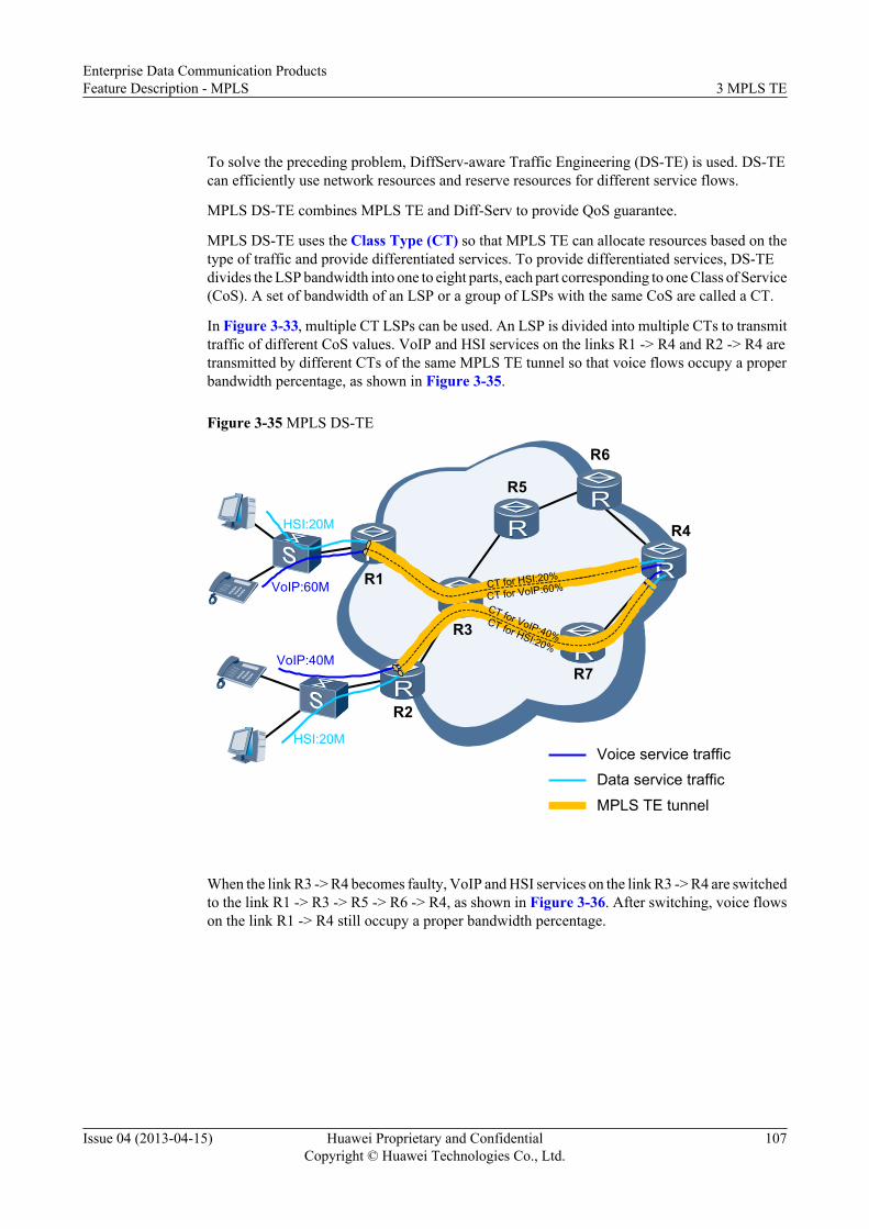
To solve the preceding problem, DiffServ-aware Traffic Engineering (DS-TE) is used. DS-TEcan efficiently use network resources and reserve resources for different service flows.
MPLS DS-TE combines MPLS TE and Diff-Serv to provide QoS guarantee.
MPLS DS-TE uses the Class Type (CT) so that MPLS TE can allocate resources based on thetype of traffic and provide differentiated services. To provide differentiated services, DS-TEdivides the LSP bandwidth into one to eight parts, each part corresponding to one Class of Service(CoS). A set of bandwidth of an LSP or a group of LSPs with the same CoS are called a CT.
In Figure 3-33, multiple CT LSPs can be used. An LSP is divided into multiple CTs to transmittraffic of different CoS values. VoIP and HSI services on the links R1 -> R4 and R2 -> R4 aretransmitted by different CTs of the same MPLS TE tunnel so that voice flows occupy a properbandwidth percentage, as shown in Figure 3-35.
Figure 3-35 MPLS DS-TE
R1
R2
R6
R4
R7
R5
R3
HSI:20M
HSI:20M
VoIP:40M
VoIP:60M CT for HSI:20%
CT for VoIP:60%
CT for VoIP:40%CT for HSI:20%
Voice service trafficData service traffic
MPLS TE tunnel
When the link R3 -> R4 becomes faulty, VoIP and HSI services on the link R3 -> R4 are switchedto the link R1 -> R3 -> R5 -> R6 -> R4, as shown in Figure 3-36. After switching, voice flowson the link R1 -> R4 still occupy a proper bandwidth percentage.
Enterprise Data Communication ProductsFeature Description - MPLS 3 MPLS TE
Issue 04 (2013-04-15) Huawei Proprietary and ConfidentialCopyright © Huawei Technologies Co., Ltd.
107

Figure 3-36 Traffic switching after a link failure
R1
R2
R6
R4
R7
R5
R3
HSI:20M
HSI:20M
VoIP:40M
VoIP:60M
CT for HSI:20%
CT for VoIP:40%CT for HSI:20%
CT for VoIP:60%
Voice service trafficData service traffic
MPLS TE tunnel
Link fault
3.2.10.2 Basic Concepts
DS Field
To carry out the Diff-Serv model, RFC 2474 redefines the ToS field in the IPv4 packet headeras the Differentiated Services (DS) field. The high-order 2 bits in the DS field are reserved, andthe low-order 6 bits specify the DS CodePoint (DSCP).
Per Hop Behavior
Per Hop Behavior (PHB) describes how the packets with the same DSCP value are forwardedto the next hop.
The IETF defines three standardized PHBs: expedited forwarding (EF), assured forwarding(AF), and best-effort (BE). BE is the default PHB.
CT
To carry out differentiated services, the DS-TE model divides the bandwidth of an LSP into oneto eight parts. Each part of bandwidth is allocated with a different service class. The set ofbandwidth of one LSP or a group of LSPs with the same service class is called a class type (CT).One CT can transmit the traffic of a single service type.
As defined in the IETF, the DS-TE supports a maximum of eight CTs. CTs can be representedas CTi. The value of "i" ranges from 0 to 7.
Enterprise Data Communication ProductsFeature Description - MPLS 3 MPLS TE
Issue 04 (2013-04-15) Huawei Proprietary and ConfidentialCopyright © Huawei Technologies Co., Ltd.
108

IGP Extension
To support DS-TE. RFC 4124 uses a Bandwidth Constraints Sub-TLV into the Interior GatewayProtocol (IGP) and redefines the Unreserved Bandwidth Sub-TLV. These Sub-TLVs are usedto collect and advertise information about the reservable bandwidth for each CT along a link.For details, see RFC 4124.
Single-CT LSP and Multi-CT LSP
A single-CT LSP transmits traffic of only one CT.
A multi-CT LSP transmits traffic of multiple CTs.
For the multi-CT, the resource reservation, LSP establishment, or bandwidth preemption can besuccessfully performed only when the bandwidth of all the CTs is sufficient.
LSP Preemption and TE-Class Mapping
If no path meets the bandwidth requirement of a desired CR-LSP, a device can tear down anestablished CR-LSP and use the bandwidth assigned to that CR-LSP to establish a desired CR-LSP. This process is called preemption. DS-TE uses setup and holding priorities to determinewhether to preempt resources.
DS-TE specifies a preemption priority for each CT. A TE-class is a combination of a CT and apriority, which is described as follows:
TE-Class[n] = <CTi, priority>
i and the priority value range from 0 to 7, and n identifies a TE class.
The priority indicates the priority of CR-LSP preemption, and is not the value of the EXP fieldin the MPLS packet header. The value of preemption priority ranges from 0 to 7. A smaller valueindicates a higher priority. A CR-LSP can be set up only when both the combination of its CTand setup priority (<CT, setup-priority>) and the combination of its CT and holding priority(<CT, hold-priority>) exist in the TE-class mapping table. For example, the TE-class mappingtable of a certain node contains only TE-class[0] = <CT0, 6> and TE-class[1] = <CT0, 7>.
Only the following types of CR-LSPs can be set up successfully:
l Class-Type = CT0, setup-priority = 6, hold-priority = 6
l Class-Type = CT0, setup-priority = 7, hold-priority = 6
l Class-Type = CT0, setup-priority = 7, hold-priority = 7
NOTE
The CR-LSPs of "Class-Type = CT0, setup-priority = 6, hold-priority = 7" cannot be configured. This isbecause the setup priority of the CR-LSP cannot be higher than its holding priority.
Each of eight CTs can be combined with any of eight priorities, so there are 64 TE-classes. Onthe device, eight TE-classes can be configured manually.
A TE-class mapping table consists of a set of TE-classes. You are advised to configure all theLSRs with the same TE-class mapping table over an MPLS network. The device has the defaultTE-class mapping table.
Enterprise Data Communication ProductsFeature Description - MPLS 3 MPLS TE
Issue 04 (2013-04-15) Huawei Proprietary and ConfidentialCopyright © Huawei Technologies Co., Ltd.
109

Table 3-21 Default TE-class mapping table
TE-Class CT Priority
TE-Class[0] 0 0
TE-Class[1] 1 0
TE-Class[2] 2 0
TE-Class[3] 3 0
TE-Class[4] 0 7
TE-Class[5] 1 7
TE-Class[6] 2 7
TE-Class[7] 3 7
BandwidthMPLS DS-TE involves the following types of bandwidth:l Total link bandwidth: is physical link bandwidth.l Maximum reservable bandwidth: is the maximum bandwidth that a link can reserve for an
MPLS TE tunnel to be established. The maximum reservable bandwidth must be lowerthan or equal to the total link bandwidth.
l CT bandwidth: is the bandwidth of service traffic of each type on each DS-TE tunnel.l BC bandwidth: is the bandwidth reserved for all CTs along a link.
Figure 3-37 Relationship between bandwidths
CT0
CT0
CT1
CT1
Bandwidth of BC0
Bandwidth of BC1
Total link bandwidth
Maximum Reservable Bandwidth
Link through which a tunnel
passes Tunnel B
Tunnel A
Enterprise Data Communication ProductsFeature Description - MPLS 3 MPLS TE
Issue 04 (2013-04-15) Huawei Proprietary and ConfidentialCopyright © Huawei Technologies Co., Ltd.
110

Bandwidth Constraints ModelBandwidth constraint model defines the maximum number of bandwidth constraints and whichCTs each bandwidth constraint applies to and how to use BC bandwidth.
The IETF defines the following bandwidth constraints models:
l Russian Dolls Model (RDM): CTs can share bandwidth. The BC model ID of the RDM is0.The bandwidth of BC0 is less than or equal to the maximum reservable bandwidth of a link.In Figure 3-38:– Total bandwidth of all LSPs from CT0, CT1, ... CT7 ≤ Bandwidth of BC0 ≤ Maximum
reservable bandwidth– Total bandwidth of all LSPs from CT1, CT2, and CT7 ≤ Bandwidth of BC1– ...– Total bandwidth of all LSPs from CT7 ≤ Bandwidth of BC7
Figure 3-38 RDM
……BC0 for
CT0+CT1+…+CT7
BC1 for CT1+CT2+…+CT7 BC7 for
CT7
Maximum Reservable Bandwidth
For example, the bandwidth of a link is 100 Mbit/s, RDM is used, and three CTs aresupported, that is, CT0, CT1, and CT2. CT0, CT1, and CT2 transmit BE, AF, and EF trafficrespectively. The bandwidths of BC0, BC1, and BC2 are 100 Mbit/s, 50 Mbit/s, and 20Mbit/s respectively. The total bandwidth of all LSPs transmitting EF traffic cannot be largerthan 20 Mbit/s; the total bandwidth of all LSPs transmitting AF and EF traffic cannot belarger than 50 Mbit/s; the total bandwidth of all LSPs cannot be larger than 100 Mbit/s.The RDM allows bandwidth preemption between CTs. If 0 ≤ m < n ≤ 7 and 0 ≤ i < j≤ 7, the CTi of priority m can preempt the bandwidth of CTi of priority n and the bandwidthof CTj of priority n. For example, CT0 with priority 3 can preempt the bandwidth of CT0with priority 5 and the bandwidth of CT1 with priority 0. The total bandwidth of CTi of allLSPs cannot exceed the bandwidth of BCi.
l Maximum Allocation Model (MAM): One BC is mapped to one CT, and CTs cannot sharebandwidth. The BC mode ID of the MAM is 1.
Enterprise Data Communication ProductsFeature Description - MPLS 3 MPLS TE
Issue 04 (2013-04-15) Huawei Proprietary and ConfidentialCopyright © Huawei Technologies Co., Ltd.
111

Figure 3-39 MAM
……
BC0 for CT0
BC1 for CT1
BC7 for CT7
Maximum Reservable Bandwidth
In the MAM, the total bandwidth of CTi along an LSP cannot be larger than that of BCi (0≤ i ≤ 7). The total bandwidth of BCs cannot be larger than the maximum reservablebandwidth.For example, the bandwidth of a link is 100 Mbit/s, MAM is used, and three CTs aresupported, that is, CT0, CT1, and CT2. BC0 is 20 Mbit/s and transmits CT0 traffic (forexample, BE traffic); BC1 is 50 Mbit/s and transmits CT1 traffic (for example, AF traffic);BC2 is 30 Mbit/s and transmits CT2 traffic (for example, EF traffic). The total bandwidthof all LSPs transmitting BE traffic cannot be larger than 20 Mbit/s; the total bandwidth ofall LSPs transmitting AF traffic cannot be larger than 50 Mbit/s; the total bandwidth of allLSPs transmitting EF traffic cannot be larger than 30 Mbit/s.
l Extended-MAM: Similar to the MAM, extended-MAM maps one BC to one CT and CTScannot share the bandwidth. The BC mode ID of the extended-MAM is 254.The extended-MAM supports eight more implicit CTs (the combination of CT0 and eightpriorities). This is different from the MAM.Extended-MAM redefines Unreserved Bandwidth Sub-TLV and Bandwidth ConstraintSub-TLV advertised by an IGP. Unreserved Bandwidth Sub-TLV carries unreservedbandwidth for eight TE-classes. Bandwidth Constraint Sub-TLV carries information aboutthe BC model and unreserved bandwidth for eight TE-classes so that the device supportsa maximum of 16 TE-classes.When device A that has Extended-MAM configured functions as the transit or egress node,device B configured with DS-TE in non-IETF mode functions as the ingress node andcreates a dynamic CR-LSP, and the TE-class (<CT0, priority>, 0 ≤ priority ≤ 7) of theCR-LSP is not defined in the TE-class mapping table specified on device A, the CR-LSPcreation request is valid.
Table 3-22 lists the comparisons between the three bandwidth constraints models.
Table 3-22 Comparisons between the three bandwidth constraints models
Item RDM MAM/Extended-MAM
BC-CT mapping Maps one BC to one or moreCTs.
Maps one BC to one CT,which is easy for bandwidthmanagement.
Enterprise Data Communication ProductsFeature Description - MPLS 3 MPLS TE
Issue 04 (2013-04-15) Huawei Proprietary and ConfidentialCopyright © Huawei Technologies Co., Ltd.
112

Item RDM MAM/Extended-MAM
Bandwidth preemption Is unable to divide CTbandwidth and requirespreemption to providesufficient bandwidth for CTs.
Divides CT bandwidth andprovides sufficientbandwidth for CTs.
Bandwidth use efficiency Efficiently uses bandwidth. Wastes bandwidth.
3.2.10.3 Implementation
Basic ImplementationEdge nodes in the Diff-Serv model divide the traffic into several classes, and add classinformation into the DSCP field in packets. The internal node selects a proper PHB for a packetaccording to the DSCP field.
The EXP field in the MPLS packet header contains information relavant to the Diff-Serv model.The key to implement DS-TE is how to map the DSCP field (with a maximum of 64 values) tothe EXP field (with a maximum of eight values). RFC 3270 defines the following solutions:
l Label-Only-Inferred-PSC LSP (L-LSP): The drop priority is specified in the EXP field andthe PHB is determined by the label value. During packet forwarding, the label determinesthe packet forwarding path and allocates a PHB for the path.
l EXP-Inferred-PSC LSP (E-LSP): The PHB and the drop priority are specified in the EXPfield of the MPLS label. During packet forwarding, the label value determines the packetforwarding path and the EXP value determines a PHB. The E-LSP is applicable to networksthat supports a maximum of eight PHBs.
The device implements the E-LSP. The device maps DSCP or EXP priorities to local priorities.Table 3-23 lists the default mapping. DS-TE map local priorities to CTs and separately allocatesresources to each CT. Therefore, DS-TE LSPs are set up according to the CT. That is, the DS-TE calculates the path and reserves resources based on the CT and its bandwidth.
Table 3-23 Default mapping between DSCP priorities, local priorities, and EXP priorities
DSCP Priority Local Priority EXP Priority
0-7 0 0
8-15 1 1
16-23 2 2
24-31 3 3
32-39 4 4
40-47 5 5
48-55 6 6
56-63 7 7
Enterprise Data Communication ProductsFeature Description - MPLS 3 MPLS TE
Issue 04 (2013-04-15) Huawei Proprietary and ConfidentialCopyright © Huawei Technologies Co., Ltd.
113

RSVP ExtensionsIETF extends RSVP to implement DS-TE in IETF mode. RFC 4124 defines a CLASSTYPEobject for Path messages. The IETF draft (draft-minei-diffserv-te-multi-class-02) defines theextended-classtype object that carries CT information about the E-LSP. For details, see RFC4124 and draft-minei-diffserv-te-multi-class-02.
DS-TE LSP SetupThe DS-TE LSP setup process is similar to MPLS-TE LSP Setup. The difference is as follows:l The RSVP Path message contains CT information.l When receiving the RSVP Path message carrying CT information, the LSR check whether
<CT, priority> exists in the local TE-class mapping table and whether CT bandwidth issufficient. If <CT, priority> exists in the local TE-class mapping table and CT bandwidthis sufficient, a new LSP can be set up.
l After the LSP is successfully set up, the LSR recalculates the reservable bandwidth for eachCT. Information about the reservable bandwidth is then sent to an IGP, and the IGPadvertises the information to other nodes over the network.
Figure 3-40 DS-TE LSP setup process
Path1 Path2 Path3
Resv5Resv6Ingress Transit EgressResv4
Transit
Check whether <CT, priority> exists in the local TE-Class table and whether CT bandwidth is sufficient
DS-TE ModesThe device provides the IETF mode and non-IETF mode:
l IETF mode: indicates the mode defined by the IETF. Eight CTs are combined with eightpriorities and the combinations specify 64 TE-classes. A maximum of eight TE-classes canbe configured on the device.
l Non-IETF mode: indicates the mode not defined by the IETF. Each of the two CTs iscombined with each of eight priorities, so 16 TE-classes are available.
Table 3-24 describes their differences.
Enterprise Data Communication ProductsFeature Description - MPLS 3 MPLS TE
Issue 04 (2013-04-15) Huawei Proprietary and ConfidentialCopyright © Huawei Technologies Co., Ltd.
114

Table 3-24 Differences between the IETF mode and non-IETF mode
Item Non-IETF Mode IETF Mode
Bandwidthconstraintsmodel
Supports the MAM andRDM.
Supports the RDM, MAM, and extended-MAM.
CT Supports CT0 and CT1. Supports CT0 to CT7.
BC type Supports BC0 and BC1. Supports BC0 to BC7.
TE-classmapping table
A TE-class mapping table canbe configured but cannot takeeffect.
Supports the configuration and applicationof the TE-class mapping table.
IGP message l The Unreservedbandwidth Sub-TLVcarries the unreservedbandwidth for eight TE-classes corresponding toCT0, in byte/s.
l The sub-TLV(Unreserved Bandwidthfor Class-Type 1, type0x8001) carries theunreserved bandwidth foreight TE-classescorresponding to CT1, inbyte/s.
The CT information is carried in the sub-TLVs.The sub-TLVs are as follows:l Unreserved Bandwidth Sub-TLV
– For RDM and MAM, it carries theunreserved bandwidth for eight TE-classes, in byte/s.
– For extended-MAM, it carries theunreserved bandwidth for eight TE-classes corresponding to CT0, inbyte/s.
l Bandwidth Constraints Sub-TLV– For RDM and MAM, it carries
information about the BC model andthe BC bandwidth, in byte/s.
– For extended-MAM, it carriesinformation about the BC model andunreserved bandwidth for eight TE-classes, in byte/s.
RSVPmessages
The ADSPEC object carriesCT information.
Different objects carry CT information asfollows:l Single CT: The CLASSTYPE object
carries CT information.l Multi-CT: The EXTENDED_CLASS-
TYPE object carries CT information.
DS-TE Mode SwitchingOn the device, the non-IETF mode and the IETF mode can be switched to each other. DS-TEmode switching is described in Table 3-25.
Enterprise Data Communication ProductsFeature Description - MPLS 3 MPLS TE
Issue 04 (2013-04-15) Huawei Proprietary and ConfidentialCopyright © Huawei Technologies Co., Ltd.
115

Table 3-25 DS-TE mode switching
Item Non-IETF Mode → IETF Mode IETF Mode → Non-IETF Mode
Change intheBandwidthConstraints model
The bandwidth model isunchanged.
The bandwidth models are changed asfollows:l The extended-MAN is changed to
MAM.l The RDM is unchanged.l The MAM is unchanged.
Change inthebandwidth
The bandwidth values of BC0 andBC1 are unchanged.
Other BC values are reset to zero exceptvalues of BC0 and BC1.
Change inthe TE-Classmappingtable
If the TE-class mapping table isconfigured, it is applied.Otherwise, the default one isapplied.For information about the defaultTE-class mapping table, see Table3-21.
The TE-class mapping table is not applied.l If a TE-class mapping table is
configured, it is not deleted.l If no TE-class mapping table is
configured, the default one is deleted.
LSPdeletion
LSPs whose <CT, set-priority> or<CT, hold-priority> is not in theTE-class mapping table are deletedon the ingress node and the transitnode.
The following LSPs are deleted on theingress node and the transit node:l Multi-CT LSPsl LSPs of single CT from CT2 to CT7
DS-TE SchedulingAn ingress node marks local priorities of packets on the inbound interface based on prioritymapping or complex traffic classification. Each local priority is mapped to a CT. Packets arriveat the outbound interface with local priorities. On the outbound interface, HQoS is used toallocate bandwidth for DS-TE traffic, as shown in Figure 3-41.
Enterprise Data Communication ProductsFeature Description - MPLS 3 MPLS TE
Issue 04 (2013-04-15) Huawei Proprietary and ConfidentialCopyright © Huawei Technologies Co., Ltd.
116

Figure 3-41 HQoS scheduling
CT0CT1CT2
CT0CT1CT2
BC0-CTs
BC1-CTs
BC2-CTs
BC7-CTs
LSP1
LSP2
Queue0
Queue1
Queue2……
Queue7
Reserved bandwidth for TE
Other traffic
Physical interface
TE-Class CT0 0
TE-Class CT1 0
TE-Class CT2 0
DSCP0~7-LP0EXP0-LP0
DSCP8~15-LP1EXP1-LP1
DSCP16~23-LP2EXP2-LP2
Traffic mapping
Bandwidth Constraint
l Reserved bandwidth for TE tunnelsCertain bandwidth is reserved for all TE tunnels on a physical interface by a separate levelof queuing. This prevents other types of traffic from occupying the reserved bandwidth.
l Bandwidth guarantee for CTs on TE tunnelsA TE tunnel supports multiple CTs to transmit services of different types. End-to-endbandwidth is reserved for each CT when a CR-LSP is set up. The device allocate bandwidthto each CT from the bandwidth reserved for TE tunnels when they set up a CR-LSP. Theallocated bandwidth conforms to the bandwidth constraints in the RDM or MAM model.The guaranteed bandwidth for a CT is specified by the committed information rate (CIR).
l Traffic scheduling between CTs (total traffic of the same CT on different LSPs)Each CT maps a service type. High-priority services (such as voice services) can bescheduled using priority queuing (PQ). Services requiring bandwidth guarantee (such asprotocol and data services) can be scheduled using weighted fair queuing (WFQ). CTs aremapped to local priorities in a one-to-one mode. You can associate CTs with queue profilesand configure different scheduling modes in the queue profiles to provide differentiatedservices for CTs.
The AR provides 32 queue profiles globally configure scheduling modes for CTs. The followingtable lists the default mappings between CTs and fair queues (FQs), as shown in Table 3-26.
Table 3-26 CT scheduling
Local Priority CT FQ ConfigurableScheduling Mode
7 (CS7) CT7 7 WFQ
6 (CS6) CT6 6 WFQ
5 (EF) CT5 5 WFQ
4 (AF4) CT4 4 WFQ
3 (AF3) CT3 3 WFQ
Enterprise Data Communication ProductsFeature Description - MPLS 3 MPLS TE
Issue 04 (2013-04-15) Huawei Proprietary and ConfidentialCopyright © Huawei Technologies Co., Ltd.
117
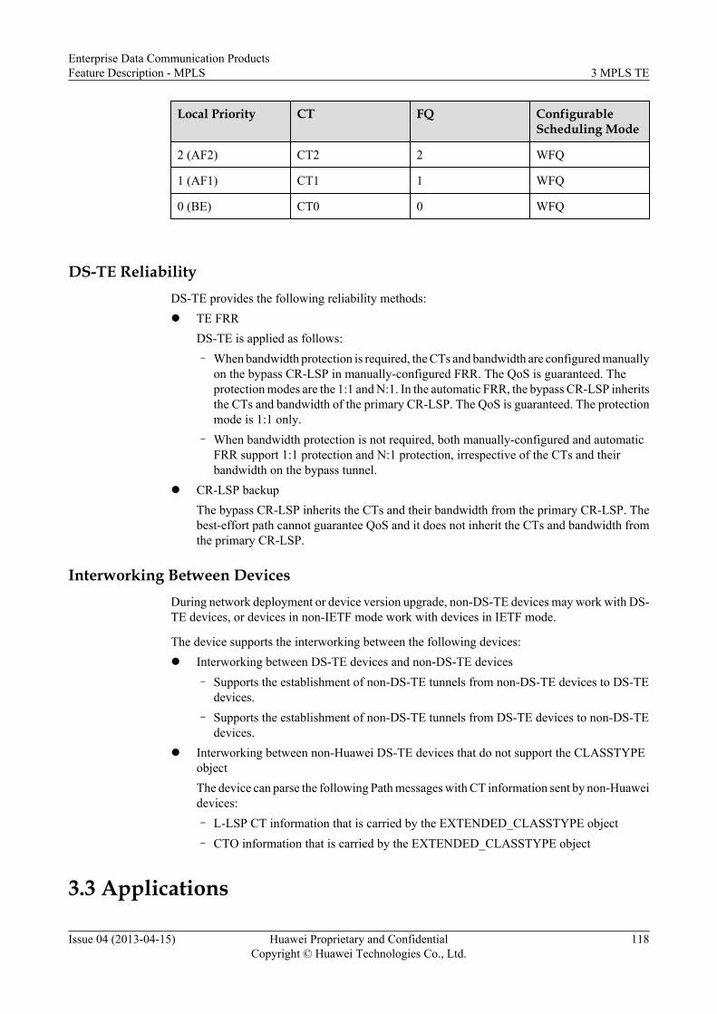
Local Priority CT FQ ConfigurableScheduling Mode
2 (AF2) CT2 2 WFQ
1 (AF1) CT1 1 WFQ
0 (BE) CT0 0 WFQ
DS-TE ReliabilityDS-TE provides the following reliability methods:l TE FRR
DS-TE is applied as follows:– When bandwidth protection is required, the CTs and bandwidth are configured manually
on the bypass CR-LSP in manually-configured FRR. The QoS is guaranteed. Theprotection modes are the 1:1 and N:1. In the automatic FRR, the bypass CR-LSP inheritsthe CTs and bandwidth of the primary CR-LSP. The QoS is guaranteed. The protectionmode is 1:1 only.
– When bandwidth protection is not required, both manually-configured and automaticFRR support 1:1 protection and N:1 protection, irrespective of the CTs and theirbandwidth on the bypass tunnel.
l CR-LSP backupThe bypass CR-LSP inherits the CTs and their bandwidth from the primary CR-LSP. Thebest-effort path cannot guarantee QoS and it does not inherit the CTs and bandwidth fromthe primary CR-LSP.
Interworking Between DevicesDuring network deployment or device version upgrade, non-DS-TE devices may work with DS-TE devices, or devices in non-IETF mode work with devices in IETF mode.
The device supports the interworking between the following devices:l Interworking between DS-TE devices and non-DS-TE devices
– Supports the establishment of non-DS-TE tunnels from non-DS-TE devices to DS-TEdevices.
– Supports the establishment of non-DS-TE tunnels from DS-TE devices to non-DS-TEdevices.
l Interworking between non-Huawei DS-TE devices that do not support the CLASSTYPEobjectThe device can parse the following Path messages with CT information sent by non-Huaweidevices:– L-LSP CT information that is carried by the EXTENDED_CLASSTYPE object– CTO information that is carried by the EXTENDED_CLASSTYPE object
3.3 Applications
Enterprise Data Communication ProductsFeature Description - MPLS 3 MPLS TE
Issue 04 (2013-04-15) Huawei Proprietary and ConfidentialCopyright © Huawei Technologies Co., Ltd.
118

3.3.1 MPLS TE Applications on an IP MAN
Service OverviewAs technology advances, service bearing networks of carriers are becoming integrated and IP/MPLS technology is of great importance after network integration. Voice, video, leased line,and data services can be uniformly transmitted over the integrated IP/MPLS network. Servicestransmitted over MANs are classified into the following two types based on user types:l Residential services: include high speed Internet (HSI), video on demand (VoD), and voice
over IP (VoIP) services.l Enterprise services: include VPN services for the headquarters and branches of large
enterprises. L3VPN services include Business VPNs and L2VPN services include data,real-time video, and real-time voice services.
Table 3-27 lists services, their quality of service (QoS), reliability, and security requirements.
Table 3-27 IP MAN services
Service QoSRequirements
Reliability Requirements Security Requirements
HSI l Bandwidth doesnot needto bereserved.
l Low QoSrequirements
l A standby link is establishedfor end-to-end (E2E)services. If an active linkfails, the services can switchto the standby link.
l Voice services must betransmitted in real time andbe rapidly switched to astandby link if an active linkfails.
l Different types of servicesare separately transmitted.
l The IP bearer networkinfrastructure can defendagainst attacks and virusesto ensure proper networkoperation.
VoD l Bandwidth needsto bereserved.
l MediumQoSrequirements
VoIP l Bandwidth needsto bereserved.
l HighQoSrequirements
Enterprise Data Communication ProductsFeature Description - MPLS 3 MPLS TE
Issue 04 (2013-04-15) Huawei Proprietary and ConfidentialCopyright © Huawei Technologies Co., Ltd.
119

Service QoSRequirements
Reliability Requirements Security Requirements
Business VPN
l Bandwidth needsto bereserved.
l MediumQoSrequirements
Networking DescriptionThe IP MAN consists of backbone and access subnetworks. The IP MAN sends services to users.Figure 3-42 shows E2E residential service networking. Figure 3-43 shows E2E enterpriseservice networking.
Figure 3-42 Residential service networking
HSI
VOD
VOIP
IP/MPLS BackBoneMAN
SR
BRAS
UPE
SoftX
HSI
VOD/VOIP
MPLS TE+VLL/VPLS
PE-AGG
PE-AGG
MPLS TE+VLL/VPLS
DSLAM
Enterprise Data Communication ProductsFeature Description - MPLS 3 MPLS TE
Issue 04 (2013-04-15) Huawei Proprietary and ConfidentialCopyright © Huawei Technologies Co., Ltd.
120

Figure 3-43 Enterprise service networking
IP/MPLS BackBone
Enterprise service
MAN
SR
BRAS
UPE
L3VPN or L2VPNMPLS TE
MPLS TE Hotstanby BFD for CR-LSP
Feature DeploymentServices shown in Figure 3-42 and Figure 3-43 are core services of carriers. These serviceshave specific bandwidth, QoS, and reliability requirements. To meet these requirements, MPLSTE tunnels can be used over virtual private networks (VPNs). Table 3-28 lists deploymentsolutions.
Table 3-28 MPLS TE over an IP MAN
Item L3VPN L2VPN
Service Business VPN l HSIl VoDl VoIP
Publicnetworktunnels forVPN services
MPLS TE tunnels MPLS TE tunnels
Enterprise Data Communication ProductsFeature Description - MPLS 3 MPLS TE
Issue 04 (2013-04-15) Huawei Proprietary and ConfidentialCopyright © Huawei Technologies Co., Ltd.
121

Item L3VPN L2VPN
Reliability l Network reliability:– Link protection: provided
using TE Hot-standby andbidirectional forwardingdetection (BFD) forconstraints-routed labelswitched path (CR-LSP).
– Node protection: providedusing VPN fast reroute (FRR)and BFD for TE tunnel.
l Device reliability: provided usingRSVP graceful restart (GR) ornon-stop routing (NSR).
l Network reliability:– Link protection: provided
using TE Hot-standby andBFD for CR-LSP.
– Node protection: providedusing virtual leased line(VLL) FRR and BFD for TEtunnel.
l Device reliability: provided usingRSVP GR or NSR.
QoS E2E QoS functions need to be deployed on a link between a user-end provideredge device (UPE) and a broadband remote access server (BRAS) or a linkbetween a UPE and a service router (SR).
Security Message digest 5 (MD5) or keychain is used to authenticate RSVP messages.
Key deployment points are as follows:l Explicit paths are configured to separately establish primary and backup CR-LSPs. The
two paths do not overlap in important areas.
3.3.2 DS-TE Applications
Application Scenario: Access of Different Services to One VPNOn VPNs with MPLS-TE tunnels, one VPN may transmit EF, AF, and BE servicessimultaneously. One MPLS TE tunnel may transmit different types of services with differentQoS requirements.
To prevent services on one MPLS TE tunnel from affecting each other, set up specific VPNsand TE tunnels to transmit specific services. This is because resources may be wasted whenmultiple VPNs and tunnels are set up for transmitting difference types of services over a networksimultaneously.
Alternatively, you can deploy DS-TE and use a multi-CT LSP to transmit services over oneVPN. A multi-CT LSP can reserve up to eight CTs. Each CT can transmit one type of servicesof one VPN. Services among different CTs does not affect each other.
As shown in Figure 3-44, VPN1 transmits EF, AF, and BE services. One DS-TE tunnel needsto be set up and configured with CT0 (100 Mbit/s), CT2 (50 Mbit/s), and CT5 (10 Mbit/s). Thetunnel is bound to VPN1 on the ingress. After traffic of VPN1 is classified, the traffic enterscorresponding CT queues.
Enterprise Data Communication ProductsFeature Description - MPLS 3 MPLS TE
Issue 04 (2013-04-15) Huawei Proprietary and ConfidentialCopyright © Huawei Technologies Co., Ltd.
122

Figure 3-44 One MPLS TE tunnel transmitting different services on one VPN
PE PE
CE CEVPN1Site 1
VPN1Site 2
CT0 for BE: 100Mbit/s CT2 for AF: 50Mbit/sCT5 for EF: 10Mbit/s
MPLS TE tunnel
Application Scenario: Access of Different Services to Different VPNsOn a VPN with MPLS-TE tunnels, multiple VPNs may share one TE tunnel. These VPNs requirespecific QoS. They compete with each other for resources, and QoS requirements of servicesover VPNs cannot be met.
The solutions to the preceding scenario are as follows:
l Multiple VPNs transmit different types of services.One TE tunnel can be used to transmit a maximum of eight types of services.For example, VPN1 and VPN2 can access the TE tunnel simultaneously. VPN1 transmitsEF and BE services and VPN2 transmits AF services. One TE tunnel needs to be set upand each type of services on each VPN is configured with a specific CT. The number ofCTs is equal to the sum of service types on VPN1 and the number of service types on VPN2.Three CTs are supported.
l Multiple VPNs transmit the same type of services.The number of TE tunnels to be set up is equal to the number of VPNs. The number of CTson each tunnel is equal to the number of corresponding service types on VPNs.For example, VPN1 and VPN2 can access the TE tunnel simultaneousl. VPN1 bears EFand BE services and VPN2 also transmits EF and BE services. Two TE tunnels can be setup for VPN1 and VPN2. Each type of services on each tunnel is configured with a specificCT.
l Multiple VPNs transmit services (some services are the same).Each VPN needs a tunnel. The number of CTs on each tunnel is equal to the number ofcorresponding service types on VPNs.
Application Scenario: Access of Traffic to VPNs and Non-VPNsQoS requirements vary with VPN traffic and non-VPN traffic. If one TE tunnel transmits all thetraffic, the VPN traffic and non-VPN traffic may compete with each other for resources, andQoS requirements of services cannot be met.
The solutions to the preceding scenario are as follows:
l The VPN and non-VPN transmit different types of services.
Enterprise Data Communication ProductsFeature Description - MPLS 3 MPLS TE
Issue 04 (2013-04-15) Huawei Proprietary and ConfidentialCopyright © Huawei Technologies Co., Ltd.
123

One TE tunnel needs to be set up. Services on the VPN and non-VPN are configured withdifferent CTs. The number of CTs is equal to the sum of the number of service types onthe VPN and the number of service types on the non-VPN.
l The VPN and non-VPN transmit the same type of services.Two TE tunnels need to be set up for the VPN and non-VPN services. Specific types ofservices on each tunnel are configured with specific CTs.
l The VPN and non-VPN transmit services (some services are the same).Two TE tunnels need to be set up for the VPN and non-VPN services. Specific types ofservices on each tunnel are configured with specific CTs.
3.4 ReferencesThe following table lists the references of this document.
Document Description Remarks
RFC 2205 Resource Reservation Protocol -
RFC 2209 Resource Reservation Protocol (RSVP) - Version 1 MessageProcessing Rules
-
RFC 2370 The OSPF Opaque LSA Option -
RFC 2547 BGP/MPLS VPNs -
RFC 2702 Requirements for Traffic Engineering Over MPLS -
RFC 2747 RSVP Cryptographic Authentication -
RFC 2961 RSVP Refresh Overhead Reduction Extensions -
RFC 3031 Multiprotocol Label Switching Architecture -
RFC 3032 MPLS Label Stack Encoding -
RFC 3034 Use of Label Switching on Frame Relay Networks Specification -
RFC 3209 RSVP-TE: Extensions to RSVP for LSP Tunnels -
RFC 3210 Applicability Statement for Extensions to RSVP for LSP-Tunnels -
RFC 3473 Generalized Multi-Protocol Label Switching (GMPLS) SignalingResource Reservation Protocol-Traffic Engineering (RSVP-TE)Extensions
-
RFC 3630 Traffic Engineering (TE) Extensions to OSPF Version 2 -
RFC 3784 Intermediate System to Intermediate System (IS-IS) Extensions forTraffic Engineering (TE)
-
RFC 4124 Protocol Extensions for Support of Diffserv-aware MPLS TrafficEngineering
-
Enterprise Data Communication ProductsFeature Description - MPLS 3 MPLS TE
Issue 04 (2013-04-15) Huawei Proprietary and ConfidentialCopyright © Huawei Technologies Co., Ltd.
124

Document Description Remarks
RFC 4127 Russian Dolls Bandwidth Constraints Model for Diffserv-awareMPLS Traffic Engineering
-
RFC 4128 Bandwidth Constraints Models for Differentiated Services(Diffserv)-aware MPLS Traffic Engineering: PerformanceEvaluation
-
RFC 4139 Requirements for Generalized MPLS (GMPLS) Signaling Usageand Extensions for Automatically Switched Optical Network(ASON)
-
RFC 4090 Fast Reroute Extensions to RSVP-TE for LSP Tunnels -
draft-ietf-mpls-nodeid-subobject-01
Definition of an RRO node-id subobject -
draft-ietf-tewg-diff-te-proto-02
Protocol extensions for support of Diff-Serv-aware MPLS TrafficEngineering
-
draft-ietf-mpls-diff-te-reqts-00
Requirements for support of Diff-Serv-aware MPLS TrafficEngineering
-
draft-ietf-mpls-diff-ext-07
MPLS Support of Differentiated Services -
Enterprise Data Communication ProductsFeature Description - MPLS 3 MPLS TE
Issue 04 (2013-04-15) Huawei Proprietary and ConfidentialCopyright © Huawei Technologies Co., Ltd.
125

4 MPLS OAM
About This Chapter
4.1 Introduction to MPLS OAM
4.2 Principles
4.3 References
Enterprise Data Communication ProductsFeature Description - MPLS 4 MPLS OAM
Issue 04 (2013-04-15) Huawei Proprietary and ConfidentialCopyright © Huawei Technologies Co., Ltd.
126

4.1 Introduction to MPLS OAM
Definition
Operation, Administration and Maintenance (OAM) is an important means to cut costs innetwork maintenance. The MPLS OAM mechanism manages operation and maintenance ofMultiprotocol Label Switching (MPLS) networks.
MPLS supports different Layer 2 and Layer 3 protocols such as IP, Frame Relay (FR), andAsynchronous Transfer Mode (ATM). In an MPLS network, the OAM mechanism is providedtotally independent of any upper or lower layer, which implements the following features on theMPLS user plane:
l Detects connectivity of label switched paths (LSPs).l Assesses utilization and performance of an MPLS network.l Performs protection switching when a defect or fault occurs on a link to provide services
in compliance with the signed service level agreements (SLAs) signed.
Purpose
As an extensible key technology of the next generation network, MPLS provides multipleservices guaranteed by quality of service (QoS). MPLS introduces a unique network layer thatmay cause faults. Therefore, MPLS networks need to support OAM.
The protocols (such as Synchronous Optical Network (SONET)/Synchronous Digital Hierarchy(SDH)) at the server layer below the MPLS network layer and the protocols (such as IP, FR, andATM) at the client layer above the MPLS network layer have their respective OAM mechanisms.Failures of the MPLS network cannot be rectified thoroughly through the OAM mechanism ofother layers. In addition, the network technology hierarchy also requires MPLS to have itsindependent OAM mechanism to decrease dependency between layers on each other.
The MPLS OAM mechanism can detect, identify, and locate a defect at the MPLS layereffectively. Then, the MPLS OAM mechanism the reports and handles the defect. In addition,when a failure occurs, the MPLS OAM mechanism can trigger protection switching.
4.2 Principles
4.2.1 MPLS OAM DetectionMPLS OAM packets can be classified into the following types:
l Connectivity detection packets
– Fast Failure Detection (FFD) packets
– Connectivity Verification (CV) packetsl Forward Defect Indication (FDI) packetsl Backward Defect Indication (BDI) packets
MPLS OAM monitors:
Enterprise Data Communication ProductsFeature Description - MPLS 4 MPLS OAM
Issue 04 (2013-04-15) Huawei Proprietary and ConfidentialCopyright © Huawei Technologies Co., Ltd.
127

l TE LSP ConnectivityMPLS OAM periodically sends CV or FFD packets along a TE LSP.
MPLS OAM for a TE LSP
Figure 4-1 MPLS OAM for a TE LSP
CV/FFD
CV/FFD
BDIBDI
IngresslSR
EngresslSR
As shown in Figure 4-1, MPLS OAM works as follows:
1. The ingress sends a CV packet or an FFD packet along an LSP to be detected. The packetpasses through the LSP and arrives at the egress.
2. The egress compares the packet type, interval, and Trail Termination Source Identifier(TTSI) in the received packet with the local values to check the correctness of the packet.In addition, the egress counts the number of received correct and incorrect packets withina detection cycle. In this manner, MPLS OAM detects connectivity of the LSP.
3. The detection interval of CV packet is a fixed value, and the detection cycle of FFD packetis three times the detection interval.
4. When the egress detects an LSP defect, the egress analyzes the defect type and sends a BDIpacket carrying the defect information to the ingress through a reverse tunnel. In thismanner, the ingress is notified of the defect of a specific type in time. If the protection groupis configured correctly, protection switching is triggered.The detected defect is of one of the following types:l Non-MPLS layer defects
– dServer: indicates a server-layer defect. A dServer defect is the server-layer defectthat occurs below an MPLS network. The defects of this type are reported by theserver layer to MPLS OAM for handling.The lower layer network that bears MPLS services may have its own protection anddefect detection mechanism. When a lower-layer defect occurs on an LSP, adownstream label switch router (LSR) that is closest to the defect can notify theegress of the defect. The lower-layer defect should not trigger the switchover but beonly notified to the network management device. In addition, the lower-layer defectcan be notified to the ingress through a proper method (of sending BDI packets).
Enterprise Data Communication ProductsFeature Description - MPLS 4 MPLS OAM
Issue 04 (2013-04-15) Huawei Proprietary and ConfidentialCopyright © Huawei Technologies Co., Ltd.
128

– dPeerME: indicates a peer maintenance entity defect. A dPeerME defect is theserver-layer defect that occurs on a peer maintenance entity outside the MPLSsubnet. The defects of this type are reported by other network layers connected tothe MPLS subnet to MPLS OAM for handling.
l MPLS layer defects– dLOCV: indicates the defect of connectivity verification loss.
A dLOCV defect occurs when no CV or FFD packet is received within threeconsecutive intervals for sending CV or FFD packets.
– dTTSI_Mismatch: indicates the defect of TTSI mismatching.A dTTSI_Mismatch defect occurs when no CV or FFD packet with a correct TTSIis received within three consecutive intervals for sending CV or FFD packets.
– dTTSI_Mismerge: indicates the defect of TTSI mismerging.A dTTSI_Mismerge defect occurs when CV or FFD packets with both correct andincorrect TTSIs are received within three consecutive intervals for sending CV orFFD packets.
– dExcess: indicates the defect of the excessive rate of receiving connectivity detectionpackets.A dExcess defect occurs when five or more correct CV or FFD packets are receivedwithin three consecutive intervals for sending CV or FFD packets.
l Other defectsdUnknown: indicates an unknown defect in an MPLS network.A defect can be defined as dUnknown. For example, if the egress detects a defect thatboth CV packets and FFD packets are sent along the same LSP, this special defect thatis not defined in the protocol can be identified as a dUnknown defect.
4.2.2 Reverse TunnelWhen the basic OAM function is configured, the LSP to be detected needs to be bound to areverse tunnel for transmitting BDI packets.
BDI packets are transmitted through the reverse tunnel. A reverse tunnel can be an LSP with theingress and egress being opposite to those on the detected LSP. The reverse tunnel can also bea non-MPLS path that connects the ingress and the egress of the detected LSP.
The reverse tunnel transmitting BDI packets can be one of the following types:
l Private reverse LSPl Shared reverse LSPl Non-MPLS reverse path
NOTE
Currently, Huawei only supports a TE tunnel as the reverse tunnel.
4.2.3 MPLS OAM Auto ProtocolMPLS OAM defined in ITU-T Recommendation Y.1710 and Y.1711 has the followingdrawbacks:
l On an LSP, if the ingress is enabled with the OAM function later than the egress, or OAMis enabled on the egress and disabled on the ingress, a dLOCV defect occurs.
Enterprise Data Communication ProductsFeature Description - MPLS 4 MPLS OAM
Issue 04 (2013-04-15) Huawei Proprietary and ConfidentialCopyright © Huawei Technologies Co., Ltd.
129

l The dLOCV defect also occurs when OAM is disabled. You must disable OAM on theingress and egress before changing the type or updating the interval for sending detectionpackets.
l The OAM parameters need to be set on the ingress and egress respectively. This, however,may cause the detection packet type and the interval for sending detection packets on theingress to be different from those on the egress.
On the Huawei devices, the OAM auto protocol can address the preceding problems.
If the OAM auto protocol is enabled on the egress, the functions of first packet triggering OAMand the dynamic enabling or disabling OAM are provided.
The MPLS OAM auto protocol is the patent of Huawei.
4.2.4 Protection SwitchingProtection switching refers to that a protection tunnel (namely, the bypass tunnel) is pre-set forthe primary tunnel and assigned with bandwidth. The primary tunnel and the bypass tunnel forma protection group. When the primary tunnel is faulty, data traffic can be quickly switched tothe bypass tunnel. This decreases the packet loss ratio or shortens the delay due to the LSPfailure, and enhances reliability of networks. Protection switching refers to the end-to-endprotection.
With MPLS OAM for fast fault detection, the protection switching can be performed inmilliseconds.
On the Huawei devices, protection switching can be performed in 1:1 mode or N:1 mode.
l In 1:1 mode, a primary tunnel and a bypass tunnel are set up between the ingress and egress.– Normally, data is transmitted through the primary tunnel.– When the ingress detects a fault on the primary tunnel through MPLS OAM, protection
switching is performed and the ingress switches data to the bypass tunnel fortransmission.
l In N:1 mode, a tunnel functions as the bypass tunnel for multiple primary tunnels. Whenany primary tunnel fails, data is switched to the shared bypass tunnel. The N:1 mode isused to save bandwidth in a network with the mesh topology.
Figure 4-2 Schematic diagram of the MPLS OAM tunnel protection
SwitchA SwitchB
Primary tunnel
Primary tunnel
Protection tunnel
Backward tunnel
Data flow when primarytunnel is normal
Data flow when primarytunnel is falled
Enterprise Data Communication ProductsFeature Description - MPLS 4 MPLS OAM
Issue 04 (2013-04-15) Huawei Proprietary and ConfidentialCopyright © Huawei Technologies Co., Ltd.
130
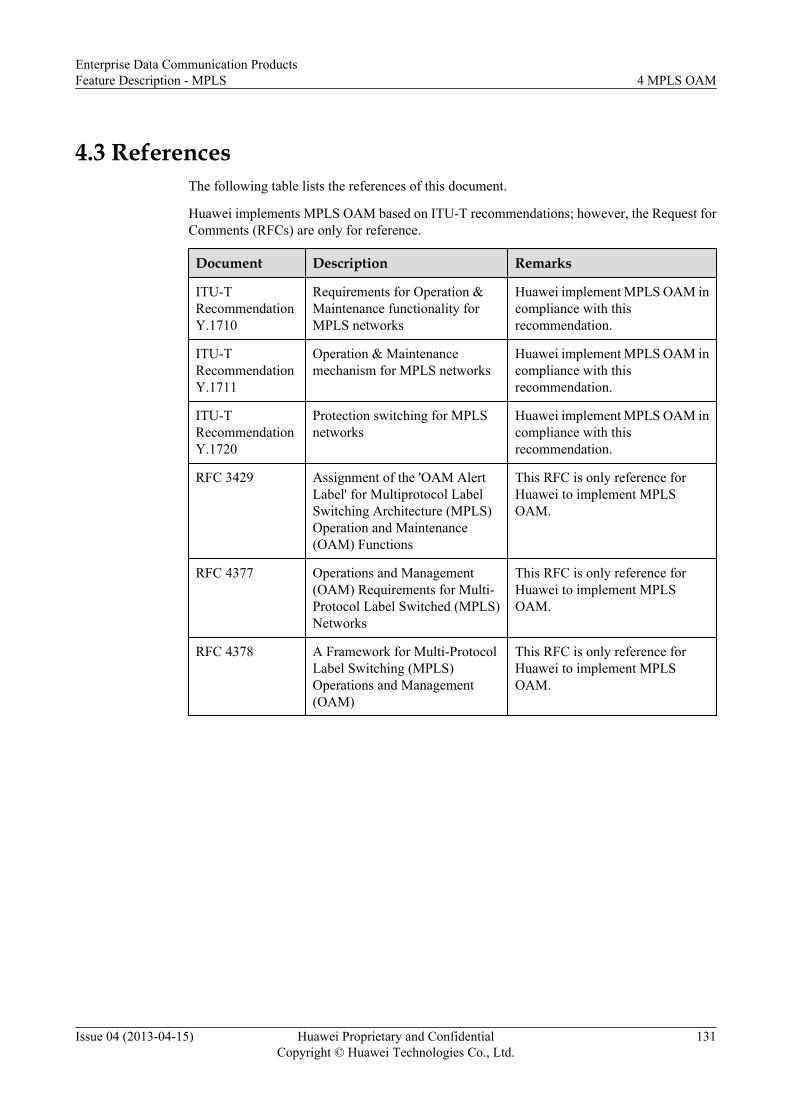
4.3 ReferencesThe following table lists the references of this document.
Huawei implements MPLS OAM based on ITU-T recommendations; however, the Request forComments (RFCs) are only for reference.
Document Description Remarks
ITU-TRecommendationY.1710
Requirements for Operation &Maintenance functionality forMPLS networks
Huawei implement MPLS OAM incompliance with thisrecommendation.
ITU-TRecommendationY.1711
Operation & Maintenancemechanism for MPLS networks
Huawei implement MPLS OAM incompliance with thisrecommendation.
ITU-TRecommendationY.1720
Protection switching for MPLSnetworks
Huawei implement MPLS OAM incompliance with thisrecommendation.
RFC 3429 Assignment of the 'OAM AlertLabel' for Multiprotocol LabelSwitching Architecture (MPLS)Operation and Maintenance(OAM) Functions
This RFC is only reference forHuawei to implement MPLSOAM.
RFC 4377 Operations and Management(OAM) Requirements for Multi-Protocol Label Switched (MPLS)Networks
This RFC is only reference forHuawei to implement MPLSOAM.
RFC 4378 A Framework for Multi-ProtocolLabel Switching (MPLS)Operations and Management(OAM)
This RFC is only reference forHuawei to implement MPLSOAM.
Enterprise Data Communication ProductsFeature Description - MPLS 4 MPLS OAM
Issue 04 (2013-04-15) Huawei Proprietary and ConfidentialCopyright © Huawei Technologies Co., Ltd.
131