Feature Analysis of Coupling Technologies for Earth System Models · exportA importB exportB 20...
51
Feature Analysis of Coupling Technologies for Earth System Models Rocky Dunlap Dr. Spencer Rugaber Dr. Leo Mark College of Computing Georgia Tech Workshop on Coupling Technologies for Earth System Modelling : Today and Tomorrow CERFACS Toulouse, France December 15-17, 2010
-
Upload
nguyentram -
Category
Documents
-
view
213 -
download
0
Transcript of Feature Analysis of Coupling Technologies for Earth System Models · exportA importB exportB 20...
Feature Analysis of Coupling Technologies for
Earth System ModelsRocky Dunlap
Dr. Spencer RugaberDr. Leo Mark
College of ComputingGeorgia Tech
Workshop on Coupling Technologies for Earth System Modelling : Today and
TomorrowCERFACS
Toulouse, FranceDecember 15-17, 2010

Background
http://www.earthsystemcurator.org
“The descriptors used for comprehensively specifying a model configuration are also needed for a scientifically useful description of the model output data.”Data curation ensures that future scientists can understand and use the data products generated today.Work continues today in partnership with the Metaforproject: http://www.metaforclimate.eu/
2

Earth System Curator Partners
• Geophysical Fluid Dynamics Laboratory, NOAA
• Earth System Modeling Framework, NOAA/ESRL
• Earth System Grid, NCAR, NESII/CIRES/NOAA
• Department of Earth, Atmospheric and Planetary Science, MIT
• Department of Earth and Atmospheric Sciences, Georgia Tech
Background
• Who are we? – Computer scientists (software engineering,
databases)• Why are we interested in coupled models?
– Large, complex software systems– Represent a synthesis of deep knowledge areas:
high performance computing & parallel programming, component development, numerical methods, earth & atmospheric sciences
– Scientific software is different than other kinds of software. Climate models are an “experimental environment” and a “research tool” that are “constantly under development.” 4

Background
• What kinds of things are we interested in?– Not just high performance couplers, improved
interpolation schemes, and planning for new hardware (although these are important!)
– Writing good code– Intentional code—that is, code that clearly shows the
intention of the developer and reflects domain-level concepts
– Abstraction, modularity, separation of concerns– Ways of reducing complexity for model developers– Not just scientific validation, but code verification
• Generative programming as a potential solution
5

Coupler Generation
• One of the primary goals identified by the Earth System Curator project is the ability to generate Earth System Model (ESM) couplers automatically based on high-level descriptions of the software modules (models) to be coupled.
• The Cupid prototype code generator was an early success. Simple drivers and couplers based on the Earth System Modeling Framework (ESMF) could be generated from descriptions of component interfaces.
6

Cupid : Domain Specific Language + Code Generator
7
Generated code

Moving Forward
• While the Cupid prototype showed that automatic generation of couplers between components with simple interfaces is feasible:– Did not leverage a large portion of the ESMF API– Did not consider the features of other coupling
technologies– Did not consider the actual coupling requirements
of production ESMs
• Observation: Coupling is not just a technicalprocess—it is essentially scientific in nature
8

9Found online at http://www.geo.uni-bremen.de/geomod/staff/gerrit/irvine/art/bretherton_color.gif
Bretherton Diagram

10
Atmosphere
Physics
Dynamics
Straightforward architecture, but…
…lots of complexity at implementation level
cam_compatm_comp_mctccsm_driver physpkg stepon tphysbc tphysacdyn_comp dp_coupl ing
This section is iterative.
Calls a series of parameterizations
Surface process coupling here
atm_ini t_mct()
cam_init()
phys_init()
stepon_init()
atm_ini t_mct()
cam_run1()
stepon_run1()
dyn_run()
d_p_coupling()
phys_run1()
tphysbc()
atm_run_mct()
cam_run2()
phys_run2()
tphysac()
stepon_run2()
p_d_coupling()
cam_run3()
stepon_run3()
cam_run4()
cam_run1()
stepon_run1()
phys_run1()

Backing up…
• What are the requirements for building an Earth System Model coupler?– Taking into account the complexities that
inevitably emerge at the implementation level
• What kinds of features must be supported?
11
Feature Analysis of Coupling Technologies
• A key step in generative programming is feature analysis, which is an attempt to understand a set of related technologies by organizing their features along orthogonal dimensions– Coupling technologies represent a family of related software
products
• A feature is an unit of user-visible functionality• The output of feature analysis is a feature model that
identifies common and variable properties of the technologies
• Once a feature model has been produced, elements can be selected from it to produce a configuration, which describes a particular family member
12

Feature Diagrams
• A feature model is expressed as a feature diagram—an annotated tree in which nodes represent features in the domain
• A feature is an element of user-visible functionality
• Nodes are connected with directed edges and edges have decorations that define the relationship between parent and child nodes
13

Notation
• The root node the diagram is called the concept node• All nodes below the concept node represent features
and subfeatures• Mandatory features are denoted by a simple edge
ending with a filled circle• Optional features are denoted by a simple edge ending
with an open circle• Subsets of features may be alternatives denoted by
connecting the edges pointing to alternatives with an arc• If an arc connecting edge is filled in, it indicates that any
subset of the alternatives may be chosen; otherwise the alternatives are mutually exclusive
14
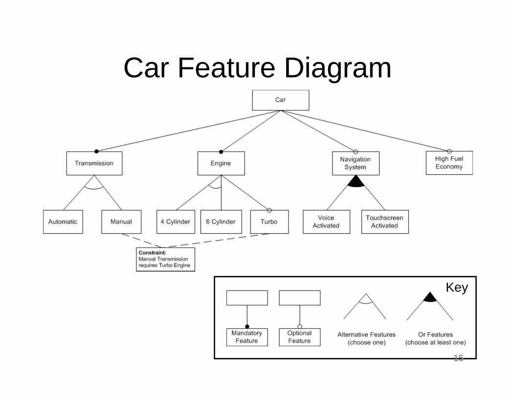
Car Feature Diagram
Key
15

Constraints
• Feature diagrams may also contain constraints that enforce dependencies among features– Mutual-exclusion constraints are used to describe
illegal combinations of features– Requires constraints indicate that the presence of one
feature requires the presence of another
16

How do feature models compare to…
• …existing taxonomies of coupling technologies?– Both introduce a vocabulary of terms that
describe essential concepts related to coupling– Feature models break down a set of related
software products into a multi-dimensional space
• …other kinds of software diagrams?– Features models do not describe how features
are structured or implemented, only what features are available and which sets of features make a valid configuration
17

Existing Taxonomies of Coupling Technologies
• Tom Bulatewicz PhD Thesis1. Four part taxonomy of coupling methodologies:– Monolithic : brute force, manual code
merging– Scheduled : model execute independently;
output of one model becomes input of another– Communication-based : send/receive calls
embedded at coupling points– Component-based : model code modularized
into components with standard interfaces1T. Bulatewicz, “Support for model coupling: An interface-based approach.” PhD Dissertation. University of Oregon, Eugene, OR, 2006. 18

Bulatewicz Taxonomyof Coupling Methodologies
for i=1,nxfor j=1,nycall dyn()call
update()end for
end for
Monolithic
for k=1,zcall
phys1(k)call
phys2(k)end for
for i=1,nxfor j=1,nyfor k=1,zcall dyn()call phys1(k)call phys2(k)call update()
end forend for
end for
Scheduled
Model AModel B
Model C
Model D
19

Bulatewicz Taxonomyof Coupling Methodologies
Communication-based
Component-based
for i=1,nxfor j=1,ny
call dyn()
send(X)call update()
end forend for
for k=1,zcall phys1(k)
receive(X)
call phys2(k)end for
Atmosphereimport
export
Ocean
import
export CouplerimportA
exportA importB
exportB
20

Jagers Comparison of Coupling Technologies
• Broad scope includes several classes of technologies:– High performance coupling (MCT, OASIS, ESMF,
CCA, HLA)– Loose coupling / Interoperability (FRAMES,
OpenMI)– Object-oriented frameworks (OMS)– GUI / Visualization (TIME)– Scientific workflow engine (Kepler)– Architectural standards (CCA, HLA)– Community development initiatives (CHyMP)
H. R. A. Jagers, "Linking Data, Models and Tools: An Overview," in International Congress on Environmental Modelling and Software Modelling for Environment's Sake, Ottawa, Canada, 2010.
21

Jagers Comparison of Coupling Technologies
• Wide range of technologies requires more a more abstract inter-comparison
• Comparison includes ten dimensions such as: – defines framework– defines interfaces– provides reference implementation– code invasiveness– plug & play / graphical– HPC support
22

Feature Diagrams versusOther Kinds of Software Diagrams
• Class diagrams show the static structure of a program in terms of classes, their attributes and operations, and how the classes are related.
• Classes are implementation-level structures.• Features, on the other hand, do not have
any structural semantics– Features do not necessarily map directly to
classes– Edges should not be interpreted to have
structural semantics such as “part-of” or “consists-of.” We want to avoid importing structural characteristics into the feature model.
23

UML Class Diagrams
Component
+ finalize() : void+ init() : void+ run() : void
GriddedComponent CouplerComponent
State
Field
Array
import
export
*
*
AttrVect
+ iList+ rList+ iAttr: int(:,:)+ rAttr: real(:,:)
GlobalSegMap
+ compid: int+ start: int(:)+ lenth: int(:)+ pe_loc: int(:)
Transfer
+ isend(AttrVect, Router, int) : void+ send(AttrVect, Router, int) : void+ irecv(AttrVect, Router, int, boolean) : void+ recv(AttrVect, Router, int, boolean) : void
Router
24

Feature Diagrams versus Other Kinds of Software Diagrams
• Software architecture diagrams show the main components in a software system and how they are inter-connected.
• Feature diagrams do not imply a certain architecture. Typically, an architecture is designed such that it can support all possible configurations of features.
• However, because features represent variation points, architectural choices can be represented as features.
25
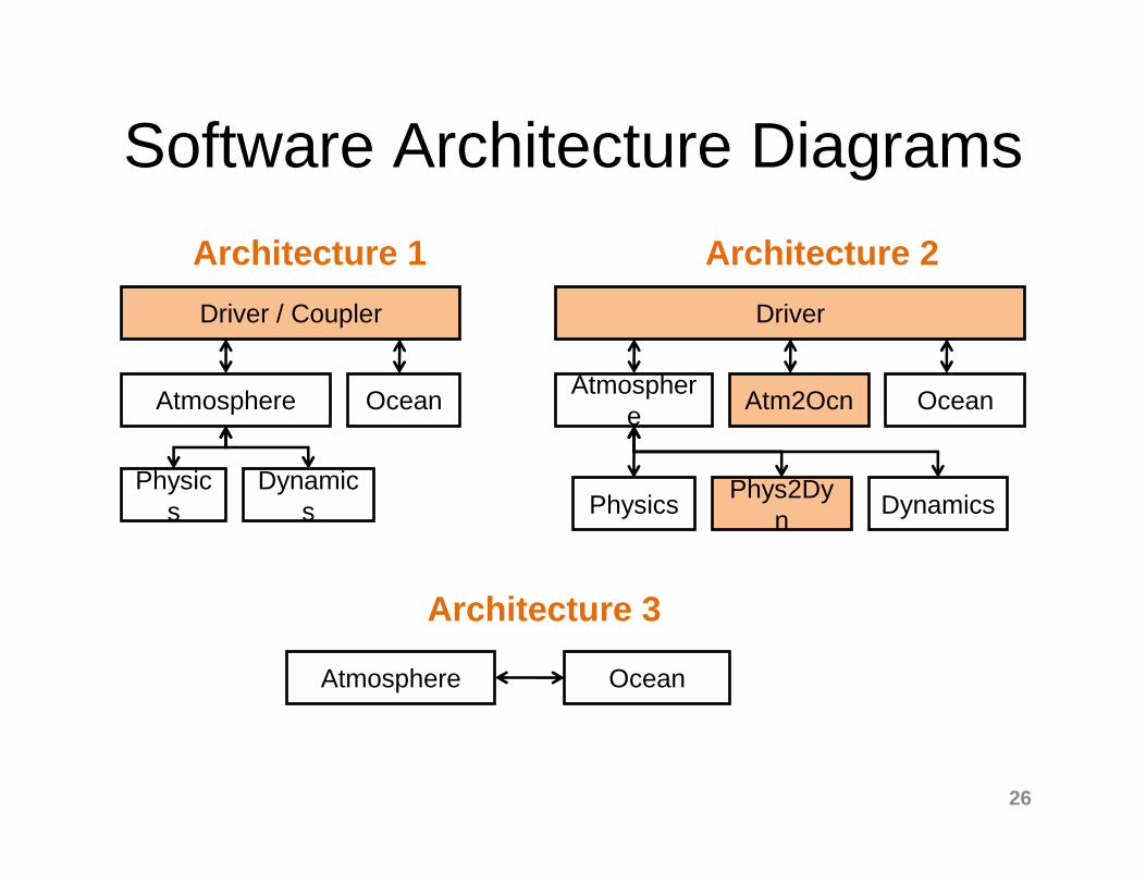
Software Architecture Diagrams
Driver / Coupler
Atmosphere Ocean
Physics
Dynamics
Driver
Atmosphere
OceanAtm2Ocn
Physics DynamicsPhys2Dy
n
Architecture 1 Architecture 2
Architecture 3
Atmosphere Ocean
26

Feature Diagrams versusOther Kinds of Software Diagrams
• Software process diagrams, such as a UML Activity Diagrams and Sequence Diagrams show behavioral aspects of a software system
• Feature diagrams are not behavior diagrams, but supported behaviors can be represented as features.– e.g., interpolation, domain decomposition
27

Technologies Reviewed
28

Approach• The feature analysis we conducted is based on
information found in technical documentation that accompanies the coupling technologies (e.g., programming guides, user manuals) as well as published scientific literature
• The initial feature analysis was conducted bottom-up by collecting a list of over 100 features used by at least one of the technologies
• We dealt with complexity by abstracting related sub-features into common higher-level features, producing a hierarchy six levels deep
• We have undergone several refactoring phases—reorganizing the feature diagram to achieve clearer levels of abstraction
29

Difficulties• We are not domain experts
• We want feature terms to be precise, while avoiding jargon and appealing to the whole community
• We sometimes had to chose among several terms describing the same concept
• When features from different base technologies overlapped, we had to distill out what the essential capability was– While maintaining orthogonality
30
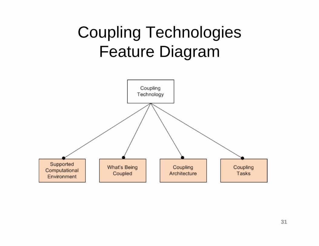
Coupling Technologies Feature Diagram
31
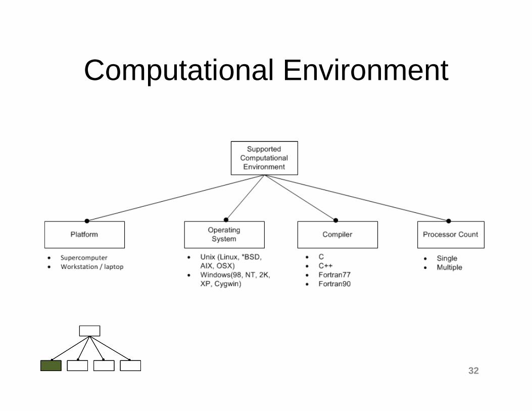
Computational Environment
32

What’s Being Coupled
33

Control and Data Interfaces to Models
34

Coupling Architecture
35

Execution Model
36

Driving
37

Coupler
38
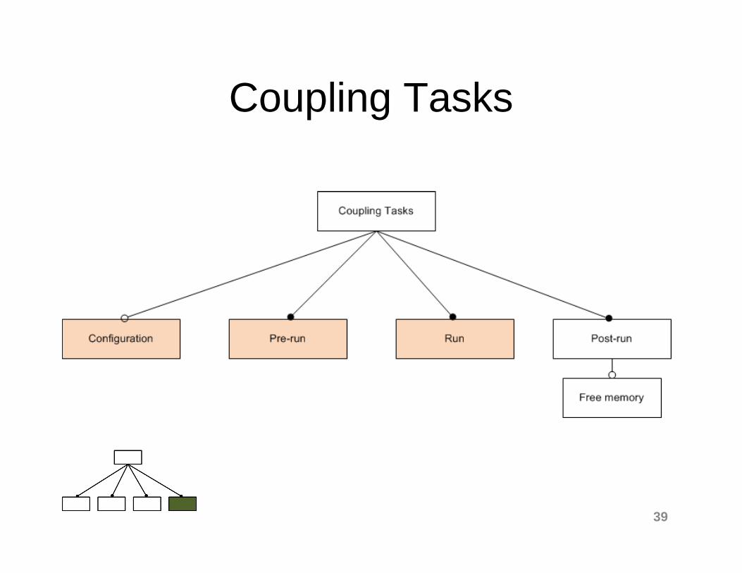
Coupling Tasks
39
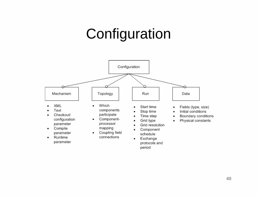
Configuration
40
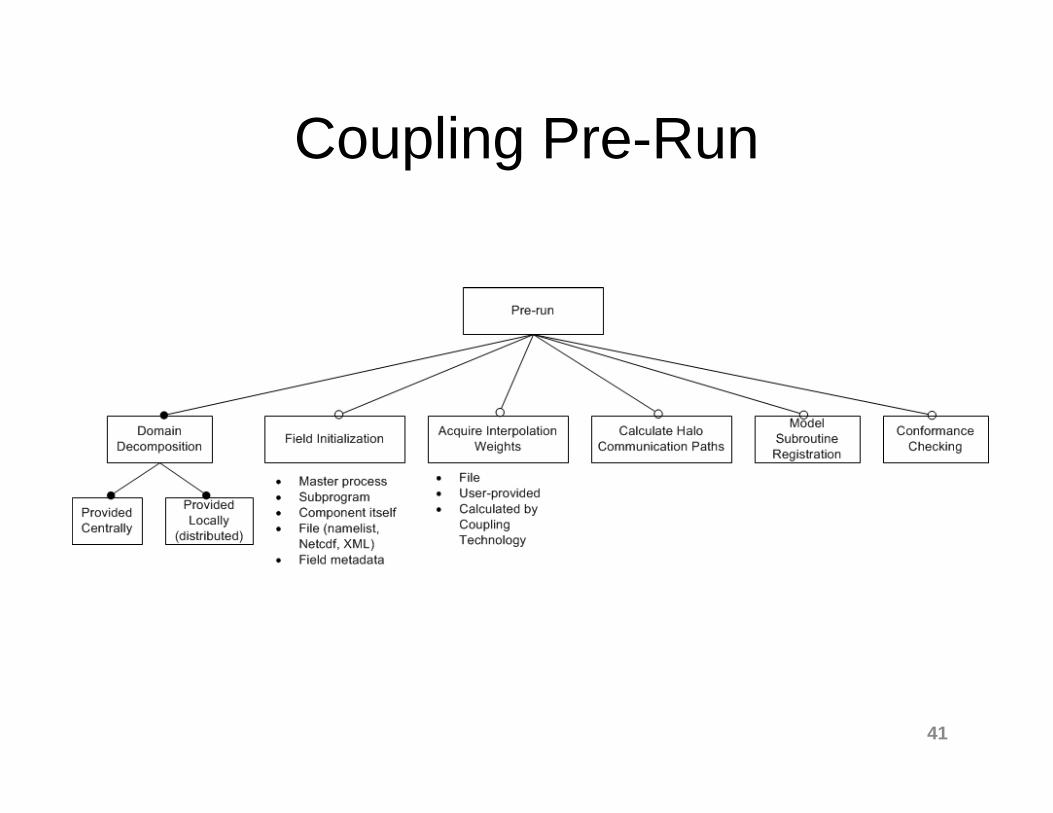
Coupling Pre-Run
41

Coupling Run
42
What’s Next?
• Validation of the feature model– Tie features back to the technology from
which they came– Compare to an alternative feature diagram
which describes production model couplers– Discussions with model developers/scientists
• Next phase of Cupid– Improve domain specific language and code
generator to handle more complex coupling requirements
43

Want to know more?• Rocky Dunlap, Spencer Rugaber, Leo Mark.
"A Feature Model of Coupling Technologies for Earth System Models.” Technical Report GT-CS-10-18, College of Computing, Georgia Institute of Technology, October 5, 2010, http://www.cc.gatech.edu/~rocky/papers/GT-CS-10-18.pdf.
• R. Dunlap, et al., "Earth System Curator: Metadata Infrastructure for Climate Modeling," Earth Science Informatics, 1(131-149), 2008.
• http://rockydunlap.wordpress.com 44

Thanks!
45

Extra Slides
46

Verification and Validation
• Verification and validation are two ways to evaluate software products:– Verification asks “Are we building the system
right?”– Validation asks “Are we building the right
system?”
• Both are related to software specifications:– Verification: Determine if the software actually
implements the specification– Validation: Determine if the specification (through
the software) meets the need for which it is intended
47
How do you do verification?
• Code inspection– Manual comparison with specification
• Static analysis• Unit testing• Integration testing• Generate provably correct code from the
specification– Domain specific language + code generator
48

Evaluation Techniques for Coupled Climate Models
• Climate models undergo rigorous evaluations1:– Model Inter-comparisons (e.g., AMIPs, IPCC)– Ensemble runs (multi-model, perturbed physics,
multiple versions of same model)– Testing against past and present climate
• Simplified tests2:– Change 3D equations of motion to 2D shallow-
water equations with analytical or reference solutions
– Isolate physical parameterizations on a single column
– Isolate dynamical core with idealized physics– “Aquaplanet” with idealized sea surface
49
1See chapter 8 of the latest IPCC Assessment Report2See Pope and Davies. “Testing and Evaluating Atmospheric Climate Models.”(2002)

Observation
• Current climate model evaluations are heavy in validation techniques, but verification techniques are largely absent
• Those verification techniques that are in use are primarily black-box techniques.– Given a certain input, ensure that the model produces the
expected output• Why is this?
– Hard to give a complete answer– I argue it is directly related to the sheer size and
complexity of climate model source code. – Model complexity is the number one enemy of
verification.• Is this a problem?
– Yes! Without verification, you cannot say with confidence exactly what you are validating. 50

Coupling should help reduce complexity and enable verification
• The good news is that most General Circulation Models (GCMs) and Earth System Models (ESMs) are built in a modular fashion.
• In general, modularity provides:– Separation of concerns– Ease of understanding– Ease of maintenance and evolution– Forces you to think about module interfaces
• But…– Even if the code is modular, the couplers
themselves become highly complex!
51