FEASIBILITY STUDY, WHABOUCHI MINE Nemaska, … · S:\1-LAB\2-Projects\1450\1452 - BBA - NEMASKA -...
53
S:\1-LAB\2-Projects\1450\1452 - BBA - NEMASKA - Whabouchi Lithium Feasibility\1. ITEM 1\Drainage - Stability\Drainage Report\1. June 2012\Report 1452-1.doc - 1 – SITE DRAINAGE, WATER BALANCE, MATERIAL QUANTITIES REQUIRED FOR CONSTRUCTION OF DRAINAGE STRUCTURES, STABILITY OF THE REJECT PILE AND SEDIMENTATION BASINS DIKES FEASIBILITY STUDY, WHABOUCHI MINE Nemaska, Québec Report no L1114521 June 2012
-
Upload
nguyenkhanh -
Category
Documents
-
view
213 -
download
1
Transcript of FEASIBILITY STUDY, WHABOUCHI MINE Nemaska, … · S:\1-LAB\2-Projects\1450\1452 - BBA - NEMASKA -...

S:\1-LAB\2-Projects\1450\1452 - BBA - NEMASKA - Whabouchi Lithium Feasibility\1. ITEM 1\Drainage - Stability\Drainage Report\1. June 2012\Report 1452-1.doc - 1 –
SITE DRAINAGE, WATER BALANCE, MATERIAL QUANTITIES REQUIRED FOR CONSTRUCTION OF
DRAINAGE STRUCTURES, STABILITY OF THE REJECT PILE AND SEDIMENTATION BASINS DIKES
FEASIBILITY STUDY, WHABOUCHI MINE Nemaska, Québec
Report no L1114521 June 2012

S:\1-LAB\2-Projects\1450\1452 - BBA - NEMASKA - Whabouchi Lithium Feasibility\1. ITEM 1\Drainage - Stability\Drainage Report\1. June 2012\Report 1452-1.doc - 2 –
TABLE OF CONTENTS
1 GENERAL .............................................................................................................................. 3 2 OBJECTIVES OF THE PRESENT STUDY .......................................................................... 3 3 QUEBEC DIRECTIVE 019 FOR THE MINING INDUSTRY FOR WATER RETENTION
STRUCTURES ....................................................................................................................... 4 4 METHODOLOGY: AVAILABLE PRECIPITATION DATA BASES AND PROPOSED
DESIGN APPROACH FOR WATER DRAINAGE AND RETENTION STRUCTURES .. 5 4.1 Historical precipitation data bases .................................................................................... 5 4.2 Data base selected for “normal” precipitation condition analyses ................................... 7 4.3 Data base selected for “extreme” precipitation condition analyses ................................. 8 4.4 Drainage structures general design concepts ................................................................. 10 4.5 Water Balance general design concepts ......................................................................... 11
5 CHARACTERISTICS OF DRAINAGE ZONES ................................................................. 12 5.1 Drainage zones ............................................................................................................... 12 5.2 Surface areas of drainage zones ..................................................................................... 14
6 ESTIMATES OF DRAINAGE WATER FLOWS AND DESIGN CAPACITY OF BASINS FOR EXTREME CONDITIONS .......................................................................................... 16
7 ESTIMATES OF DRAINAGE WATER FLOWS, CAPACITY OF BASINS, RETENTION TIME AND WATER BALANCE FOR NORMAL CONDITIONS .................................... 17
7.1 Administration and Mine Maintenance Facility (Garage) drainage flow for Normal condition. .................................................................................................................................. 17 7.2 Plant facilities drainage flow for Normal condition. ...................................................... 18 7.3 Reject Pile drainage flow for Normal condition – phase 1. ........................................... 19 7.4 Reject Pile drainage flow for Normal condition – phase 2. ........................................... 20 7.5 Open Pit drainage flow for Normal condition. ............................................................... 21
8 ESTIMATED MATERIAL QUANTITIES REQUIRED FOR CONSTRUCTION OF THE DRAINAGE STRUCTURES ................................................................................................ 22
9 REJECT PILE STABILITY ANALYSIS ............................................................................. 23 9.1 Materials and parameters used in the analyses ............................................................... 23 9.2 Results and conclusions ................................................................................................. 24
10 SEDIMENTATION BASINS DIKE STABILITY ANALYSIS .......................................... 25 10.1 Materials and parameters used in the analyses ........................................................... 25 10.2 Results and conclusions .............................................................................................. 26
11 SEEPAGE CONSIDERATIONS .......................................................................................... 27 12 REFERENCES ...................................................................................................................... 27
APPENDICES
Appendix A Climate Data Bases
Appendix B Drawings

S:\1-LAB\2-Projects\1450\1452 - BBA - NEMASKA - Whabouchi Lithium Feasibility\1. ITEM 1\Drainage - Stability\Drainage Report\1. June 2012\Report 1452-1.doc - 3 –
1 GENERAL
Nemaska Lithium proposes the construction and operation of lithium rich mines located in the James Bay area, at the northeastern zone of lake “Des Montagnes”, on Nemiscau River and the Rupert River watershed, about 40 km east of the Cree community of Nemaska. The coordinates of the center of the property are 441,000 E and 5,725,750 N (UTM Zone 18, NAD 83) (Appendix B). The deposit is located within a claim area of approximately 1,716 hectares (Appendix B), between Spodumene lake and lake “Des Montagnes”, bordering the Nemiscau River. The territory covered by this study, however, includes several water plans and rivers whose catchment areas extend beyond the mining area of the deposit and claim boundaries. The project involves:
Construction of a process plant and associated infrastructures for processing a spodumene deposit with the ultimate objective to extract lithium concentrate;
Exploitation and operation of an open pit (drilling and blasting operations) for extracting the rock;
Construction of Reject Piles in two phases where the rejected rock and “dewatered” tailings will be mixed and stored (with an outer protective layer of rejected rock) - drainage;
Construction of drainage structures (collector ditches, sedimentation basins, exit channels and culverts in the three zones described above.
Hydrology and hydrogeology studies of the site have been recently completed by WESA Envir-Eau (Ref. 1 and Ref. 2), identifying and providing the characteristics of water streams and associated watersheds, hydrological and meteorological characteristics of the site, permeability of the soils and rock, as well as estimates for dewatering the open pit during its operation life. Site Specific Meteorological data were also analyzed and presented in a memorandum of SENES Consultants Limited (Ref. 3). The present study uses the same data bases as well as estimates and conclusions of the WESA Envir-Eau hydrology and hydrogeology studies.
2 OBJECTIVES OF THE PRESENT STUDY Journeaux Assoc. was mandated by Nemaska Lithium to study and layout a drainage and water balance plan of the site including the required drainage structures, their stability, as well as geometry, methods, material types and quantities required for construction. The specific objects of the study are:

S:\1-LAB\2-Projects\1450\1452 - BBA - NEMASKA - Whabouchi Lithium Feasibility\1. ITEM 1\Drainage - Stability\Drainage Report\1. June 2012\Report 1452-1.doc - 4 –
Estimation of drainage water from run-off and dewatering (dewatering of the open pit only) for normal precipitation conditions and water balance estimate (including estimate of water volume release to neighboring natural water bodies).
Estimation of drainage water from run-off and dewatering (dewatering of the open pit only) for extreme precipitation conditions and water balance estimate (including estimate of water volume release to neighboring natural water bodies) applied to the design of the drainage structures according to Quebec Directive 019 for the Mining Industry.
Layout, design and stability of the drainage structures.
Long term stability of the Reject Piles and sedimentation dikes.
3 QUEBEC DIRECTIVE 019 FOR THE MINING INDUSTRY FOR WATER RETENTION STRUCTURES
For compliance with Quebec Directive 019 for the Mining Industry (section 2.9.3):
- Water retention structures with mining residues must be designed for a 100-year return period, if they are not acid generating. Otherwise a 1000-year return period must be used in dimensioning the structures;
- The most critical of a 6 or 24-hour duration rain must be considered in the estimation of water volumes (i.e. the one resulting in maximum water volume);
- The volume of water considered in the design flood is estimated by the sum of the critical rainfall and a 100-year return snow melt over a thirty-day period. Since the mining residues are not rendered acid generating in the case of Whabouchi mine, the most severe situation will be represented by a 1:100 precipitation and snow melt event (snow melt on a thirty-day period corresponding to the maximum expected for a 100-year return).
S:\1-LAB\2-Projects\1450\1452 - BBA - NEMASKA - Whabouchi Lithium Feasibility\1. ITEM 1\Drainage - Stability\Drainage Report\1. June 2012\Report 1452-1.doc - 5 –
4 METHODOLOGY: AVAILABLE PRECIPITATION DATA BASES AND PROPOSED DESIGN APPROACH FOR WATER DRAINAGE AND RETENTION STRUCTURES
4.1 Historical precipitation data bases
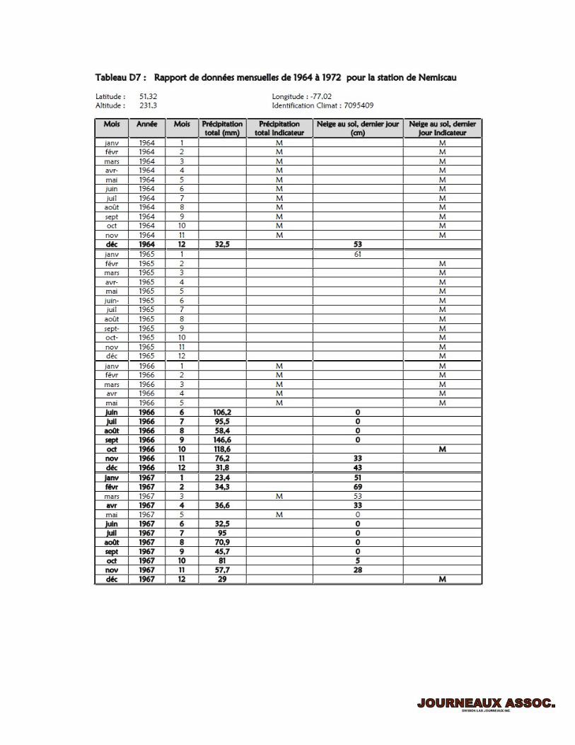
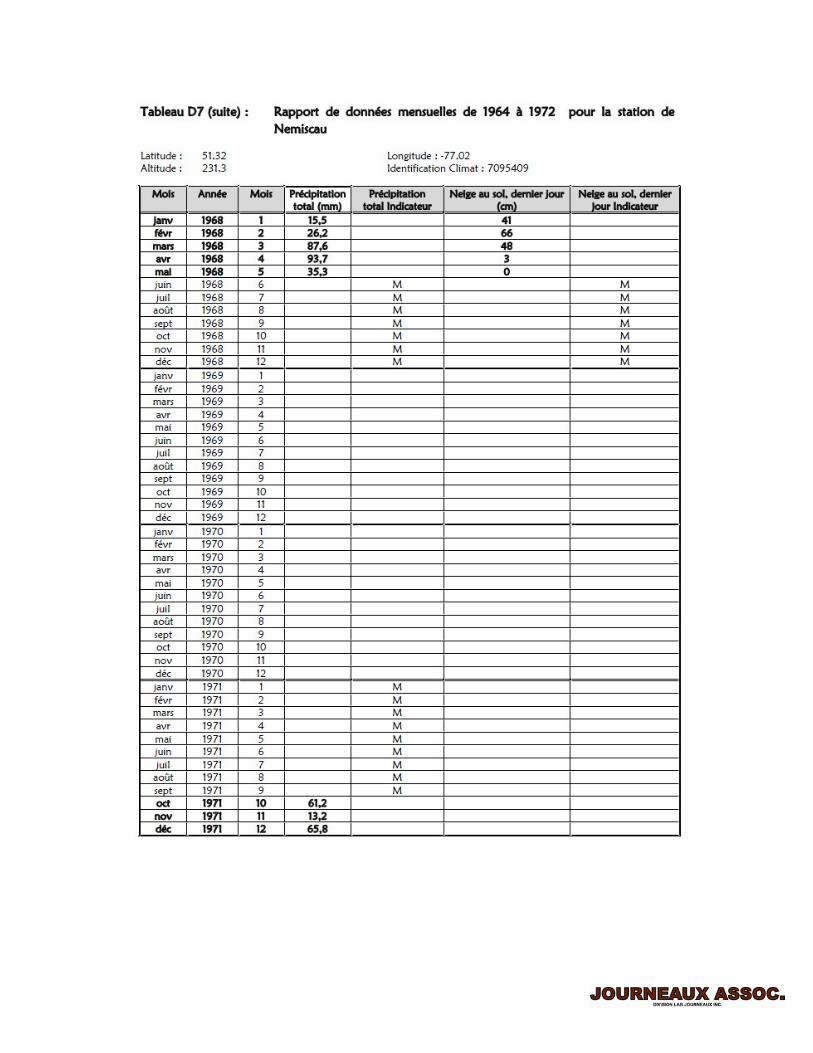
The following historical precipitation data bases, obtained from the National Climate Data and Information Archives of Environment Canada (www.climate.weatheroffice.gc.ca), were presented and analyzed by WESA Envir-Eau and SENES Consultants (Appendix A), namely:
1. Nemiscau airport, 1964-1972 data base: at a distance of approx. 20 km west from the proposed site but with limited data. No IDF (Short-duration rainfall intensity-duration-frequency statistics) data are available for this site from Environment Canada.
2. Grande Riviere A, at a distance of approx. 260 km north-west from the proposed site
with IDF data available. 3. Chapais 2, at a distance of approx. 218 km south-east from the proposed site with IDF
data available. 4. Matagami A, at a distance of approx. 253 km south-west from the proposed site with
IDF data available based. 5. Atlas of Canada - Hydrology, Climatic Atlas of Canada, The Ecological Framework of
Canada.

S:\1-LAB\2-Projects\1450\1452 - BBA - NEMASKA - Whabouchi Lithium Feasibility\1. ITEM 1\Drainage - Stability\Drainage Report\1. June 2012\Report 1452-1.doc - 6 –
S:\1-LAB\2-Projects\1450\1452 - BBA - NEMASKA - Whabouchi Lithium Feasibility\1. ITEM 1\Drainage - Stability\Drainage Report\1. June 2012\Report 1452-1.doc - 7 –
4.2 Data base selected for “normal” precipitation condition analyses
Using spatial analysis, WESA Envir-Eau estimated an average annual precipitation of 772 mm/year for the Whabouchi mine site which is 2% higher than the average annual precipitation estimated from the limited data (1964-1972) of Nemiscau airport of 756.6 mm/year. It can then be considered that the Nemiscau airport data are sufficiently representative of the Whabouchi mine site and may be used for “normal conditions” drainage and water balance analysis. Based on the Atlas of Canada, in the absence of evaporation data collected at the considered climate stations, WESA Envire-Eau suggested a value of the order of 335 mm for the Whabouchi mine site, and as noted in their report, the same source indicates an annual evapotranspiration value of 304 mm which is in the order of 40% of the total “normal” annual precipitation. Hence, it may be assumed that the “normal” run-off is generated by 60% of the sum of the recorded “normal” rain precipitation and “snow melt”. Snow melt is considered the difference between two consecutive months of the “snow on ground” recorded values at the Nemiscau airport. Table 4.1 summarizes the Nemiscau airport monthly precipitation and snow on ground data recorded, as well as the estimated monthly evapotraspiration and resulting precipitation (to produce run-off) based on the previous discussion. The annual evapotranspiration of 304 mm has been proportionally distributed to the months with rain precipitation on the assumption that there is no evapotranspiration during the winter months (although winds may produce some evaporation/drying of the snow pack) or that any evapotranspiration is reflected in the month-end snow on ground measurements. This approach is on the conservative side since some of the winter months evapotranspiration is probably included in the annual evapotranspiration measurements.

S:\1-LAB\2-Projects\1450\1452 - BBA - NEMASKA - Whabouchi Lithium Feasibility\1. ITEM 1\Drainage - Stability\Drainage Report\1. June 2012\Report 1452-1.doc - 8 –
Table 4.1 Nemiscau airport monthly precipitation, snow on ground and estimated evapotransiration data base employed in the estimation of water flows for “normal” precipitation conditions.
Month Rain mm
Snow cm
Snow on ground at month end
cm
Total available water at month end (in form of snow* or
water) mm
Evaporation Infiltration,
mm
Average daily runoff
from precipitation
and snow melt, mm
1 0.0 36.4 51.0 33.4 0.0 0.0 2 0.1 30.7 67.5 14.3 0.1 0.0 3 55.9 31.8 50.5 104.7 40.6 0.0 4 56.1 9.0 18.0 97.6 40.7 1.9 5 35.1 4.8 0.0 57.9 25.5 1.1 6 69.4 0.0 0.0 69.4 50.4 0.6 7 95.3 0.0 0.0 95.3 69.2 0.9 8 64.7 0.0 0.0 64.7 47.0 0.6 9 95.2 1.0 0.0 96.2 69.1 0.9 10 73.2 13.8 0.0 87.0 53.1 1.1 11 2.6 46.4 30.5 18.5 1.9 0.6 12 6.8 34.7 48.0 24.0 4.9 0.0
* When snow, there is no runoff
4.3 Data base selected for “extreme” precipitation condition analyses For compliance with Quebec Directive 019 for the Mining Industry (section 2.9.3):
- Water retention structures with mining residues must be dimensioned for a 100 years return period, if the mining residues are not acid generating, otherwise a 1000 years return period must be used in dimensioning the structures;
- The most critical of a 6 or 24-hour duration rain must be considered in the estimation of water volumes plus the daily average snow melt spanned over a thirty day period corresponding to a 100-year return.
Since the mining residues are not acid generating in the case of Whabouchi mine, the most severe situation is represented by a 1:100 precipitation event plus an average snow melt on a thirty-day period corresponding to a 100-year return. In the absence of IDF data and extreme snow melt for the Nemiscau airport (the data base is not sufficient to produce IDF curves and snow melt modeling), the following data were derived and used in the analyses:

S:\1-LAB\2-Projects\1450\1452 - BBA - NEMASKA - Whabouchi Lithium Feasibility\1. ITEM 1\Drainage - Stability\Drainage Report\1. June 2012\Report 1452-1.doc - 9 –
Spatial analysis of the 6 and 24-hour “extreme” rainfall (100-year return period) of the most recent bases of Chapais, Grande-Rivière and Matagami stations;
Atlas de Hauteur, Fréquence et Durée des Pluies au Québec Méridional, Québec Government, 1974.
Analysis of 1:100-year rain including snow melt extreme value analysis for Wabush lake, Labrador, Newfoundland (by the Atmospheric Environment Service), data base 1961-1997.
The spatial analysis of the IDF curves for a 6-hour and 24-hour 1:100 rainfall yielded the results shown in Table 4.2. The IDF precipitation data indicate that the 24 hour rain yields the larger water volume when compared to a 6 hours rain for any return period. Extreme snowmelt for a return period of 100 years for Wabush was estimated at 35.755 cm or 357.55 mm water equivalent in 30 days or an average of 11.9 mm per day (24 hours). Comparing the available average snowfalls at Nemiscau airport (average yearly snowfall = 20.86 cm/year, water equivalent = 208.6 mm/year, average yearly total precipitation = 756.6 mm/year) and Wabush lake A stations (average yearly snowfall = 44.57 cm/year, water equivalent = 445.7 mm/year, average yearly total precipitation = 851.6 mm/year), it is evident that Wabush receives twice as much snow. By direct proportion, a value of 47% of 11.9 mm per day (24 hours) is applied in the present study, i.e. 5.5 mm per day (24 hours). It should be noted here, that the water volume attributed to snow melt is less than 5.5 % of the total “extreme” 24-hour rainfall and hence the “error” in proportioning extreme rain including snow melt data from the Wabush lake area is very small. In addition, the “extreme” snow melt analysis contains an extreme 24 hours rainfall spaced over 30 days. Four models were used by the Canadian Climate Centre (Atmospheric Environment Service, Hydrometeorology division) for analyzing extreme snow melt in Wabush, namely: Model 1 – Eastern Canada Forested Basin Model 2 – Western North America Mountain Basin Model 3 – Western Canada Mountain Basin Model 4 – Southern Ontario Model 5 – Modified model 4 The Results of Model 1 were selected to represent the proposed Whabouchi mine site as being the most representative.

S:\1-LAB\2-Projects\1450\1452 - BBA - NEMASKA - Whabouchi Lithium Feasibility\1. ITEM 1\Drainage - Stability\Drainage Report\1. June 2012\Report 1452-1.doc - 10 –
Table 4.2 Spatial analysis for a 6 and 24 hour rain, obtained from analysis of the Chapais 2, Grande-Rivière and Matagami A IDF precipitation curves for a 100 years return period
Station Chapais 2 Grande-Rivière Matagami A
47% of Wabush
Lake, model 1
6-hr precipitation, mm 63.6 69.9 73.4 --- Average 6-hr precipitation from
spatial analysis, mm 68.4 ---
24-hr precipitation, mm 94.3 82.5 86.4 --- Average 24-hr precipitation from spatial analysis, mm 88.5 ---
Extreme 30-day snow melt, averaged as water equivalent
per 24 hours, mm --- --- --- 5.5
WORST CASE SCENARIO, 1:100-yr 24 hr precipitation,
mm 88.5 ---
WORST CASE SCENARIO, 1:100-yr 24-hr rain including
snow melt, mm 94.0 mm in 24 hours
The IDF precipitation data for Chapais 2, Grande-Rivière and Matagami A (rainfall intensity vs. duration for various return periods) and 1:100 years rain which also includes snow melt extreme value analysis for Wabush lake are displayed in Appendix A.
4.4 Drainage structures general design concepts The drainage structures for the proposed Whabouchi mine consist of:
Drainage ditches to collect water from the Administration-Garage and Plant sites. These ditches will transport the water to two or three local sedimentation basins. The water will be pumped to the Plant for use in the process.
Drainage ditches around the reject materials (waste rock mixed with dewatered tailings) that will transport the water to a sedimentation basin on the south side of the Reject Pile. The water will then be discharged to an adjacent stream through a culvert and a lined (geotextile and rip-rap) channel and will eventually reach lake “Des Montagnes”.
A drainage ditch that will transfer water (precipitation and dewatering) from the open pit to a second sedimentation basin located on the south side of the pit and near lake “Des Montagnes”. The water will then be discharged to the lake “Des Montagnes” through a culvert and a lined (geotextile and rip-rap) channel.
S:\1-LAB\2-Projects\1450\1452 - BBA - NEMASKA - Whabouchi Lithium Feasibility\1. ITEM 1\Drainage - Stability\Drainage Report\1. June 2012\Report 1452-1.doc - 11 –
The general design concepts for the drainage structures for the proposed Whabouchi mine are summarized as:
A berm is placed on the ditch bank opposite to the zone to be drained such that drainage
water from the natural watershed will not be collected in the drainage ditches. Their capacity will be sufficient to contain the extreme condition of 100-year return of precipitation and snow melt without flooding (at least 1 meter freeboard).
Peripheral berms around the sedimentation basins (excavated basins) of the Administration and Plant sites will prevent water from the surrounding watershed to enter these basins and, as a result, increase the recirculated water volume.
The peripheral berms will prevent run-off water to enter the various drainage structures and mix, dilute or segregate with mine effluents (compliance with Quebec Directive 019 for the Mining Industry, article 2.1.5).
The Reject Pile and Open pit sedimentation basins are designed with low impermeable
dikes and will be sufficient to contain the 100-year return of precipitation and snow melt flood (at least 1 meter freeboard). Under “normal” flow conditions, the water will be given sufficient time to sediment in the basin before exiting through a culvert positioned in the dike above a predetermined elevation determined for the water residence time required for sedimentation. In case of an “extreme” precipitation event, the water will surpass the elevation of the culvert to a maximum of 1 meter below the crest of the dike. This water will subsequently exit the basin through the culvert which is designed with a gate to control the output flow rate.
Progressive vegetation of the reject pile will reduce the release of fine materials. Further sedimentation control will be provided along the length of the drainage ditches by introducing various types of small catchment basins (by enlarging and/or deepening the ditches) and silt traps (rip-rap mounts, hay balls, etc.).
4.5 Water balance general design concepts The general design concepts for drainage water balance and discharge are:
Water will be collected only from the three zones of operation, namely Administration-Garage-Plant, Reject Pile and Open Pit. All other natural run-off will follow the natural watersheds around these three operation zones and will not be allowed to enter the drainage structures by protecting them with berms as described in the previous section.
The water collected in the drainage ditches and sedimentation basins from the Administration-Garage and Plant sites (pads) will be recirculated for processing. Thus no water from these zones will be released to nature.

S:\1-LAB\2-Projects\1450\1452 - BBA - NEMASKA - Whabouchi Lithium Feasibility\1. ITEM 1\Drainage - Stability\Drainage Report\1. June 2012\Report 1452-1.doc - 12 –
The water collected from the reject pile and open pit will eventually run-off into the lake “Des Montagnes” in two distinct locations: on the south side of the reject pile (south-west limit of the proposed mine site through the existing water creek) and south of the open pit (south-east limit of the proposed mine site). Lined channels are designed to carry the water exiting from the sedimentation basins towards the creek and the lake. These channels become wider at their exit such that the flow rate and corresponding water velocity is further minimized.
“Normal” operation conditions water balance estimates were based on the mean Canadian Normals discussed in section 4.2. It is assumed that there are no flows in the period of December to March as almost all precipitation is snow and the air temperature is below zero. However, during spring, the snow melt is incorporated as the difference between snow melt of two consecutive months (snow on ground at month end) until there is no more snow on the ground.
For “extreme” operation conditions, the 100-year return 24-hour rain plus a 30 day
1:1000-year snow melt (see section 4.3) is employed in the estimation of water flows.
5 CHARACTERISTICS OF DRAINAGE ZONES
5.1 Drainage zones
The Whabouchi Lithium mine project includes the following main zones which are also zones of water drainage and collection:
1. Administration and Mine Maintenance Facility (garage): The drainage water will be collected in peripheral ditches, it will be allowed to sediment into a treatment basin and then it will be pumped back for use as process water.
2. Plant: The drainage water will be collected in peripheral ditches, it will be allowed to sediment into a treatment basin and then it will be pumped back for use as process water.
3. Open Pit: The precipitation water and any water seepage from the rock pit slopes will be collected, pumped to ground surface and then flow to a sedimentation basin by means of a ditch and subsequently be released to the lake “Des Montagnes.
4. Reject Pile: The precipitation water will be collected in drainage ditches, flow to a sedimentation basin, released to the nearby creek which will subsequently carry the water to lake “Des Montagnes. Due to topography, the water will be collected by two drainage ditches, one running along the west side of the pile, the other running along the east side of the pile. Both ditches will run from north to south. The reject pile will be built in two phases. The sections of the east and west drainage ditches constructed on the north side of the Reject Pile during phase 1 will be filled as phase 1 is completed and the ditches will be extended to the north side of the Reject pile of phase 2.
The layout of the proposed mine site is shown in, Appendix B.

S:\1-LAB\2-Projects\1450\1452 - BBA - NEMASKA - Whabouchi Lithium Feasibility\1. ITEM 1\Drainage - Stability\Drainage Report\1. June 2012\Report 1452-1.doc - 13 –
The sedimentation basins that will receive the drainage water from the open Pit and Reject Pile, will be located near the lake “Des Montagnes” on the south side of the Reject Pile and Open Pit, respectively. Impermeable dikes will ensure controlled flow of water through a culvert to a lined (rip-rap and geotextile) channel to the lake. The impermeable core of the dikes will be constructed with low permeability silty till, if available, or an impermeable membrane, if till is not available. Lining the “exit” channel will prevent erosion and contamination with fines of the previously “polished” water. The drainage ditches will not be lined. A berm on the side of the ditches opposite to the Reject Pile, made with the excavated material will prevent other surface run-off water to enter the ditches and mix with the drainage water collected from the pile. Similarly, a berm will be placed at the “outside” crest of the drainage peripheral ditches of the Administration, Mine Maintenance facility and Plant. Finally, both sides of the drainage ditch from the Open Pit to the sedimentation basin will be bermed. The minimum height of all berms shall be 1 meter. All berms will be built with the material excavated during construction of the ditches and sedimentation basins. Since no acid generation is expected, construction of impermeable drainage structures (except the dikes of the sedimentation basins) is not necessary. The native soil is generally fine silts and sands of relatively low permeability, of thickness ranging from 0.5 to 4 meters and sitting on rock. Infiltration of water from the ditches and sedimentation basins towards nearby water bodies will be slow (order of 4 meters/year, Ref. 2) and any fines in the drainage water will be captured by the native soil. In the long term, the permeability of the bottom materials of the ditches and basins will reduce as fines are sedimented from the drainage water. A minimum freeboard of 1 meter has been allowed in the design of all drainage structures. Outflow water from the sedimentation basins 1 and 2 (Reject pile and Open Pit) will be regularly sampled and tested for compliance with Quebec Directive 019 for the Mining Industry (article 2.1.1.2). Table 5.1 summarizes the various drainage structures and corresponding locations.

S:\1-LAB\2-Projects\1450\1452 - BBA - NEMASKA - Whabouchi Lithium Feasibility\1. ITEM 1\Drainage - Stability\Drainage Report\1. June 2012\Report 1452-1.doc - 14 –
Table 5.1 Drainage structures and locations
Structure type Zone Location
Ditch towards Administration- Mine Maintenance Facility sedimentation basin Administration, Mine
Maintenance Facility (Garage)
Surrounding the Administration, Mine
Maintenance Facility (Garage) zone
Sedimentation Basin and pump to processing.
West side of Administration, Mine Maintenance Facility
(Garage)
Ditch towards Plant sedimentation basin Plant
Surrounding the Plant zone
Sedimentation Basin and pump to processing. East side of Plant
West side ditch towards Reject Pile sedimentation basin (Basin 1).
Reject materials Pile
West side of Reject materials Pile
East side ditch towards Reject Pile sedimentation basin (Basin 1). Culvert under the mine road to the reject pile.
East side of Reject materials Pile
Sedimentation basin discharging through a culvert into lined exit channel to the adjacent creek ending in lake “Des Montagnes”. Culvert flow is regulated with a gate.
South of Reject materials Pile
Ditch from Open Pit towards Open Pit sedimentation basin (Basin 2).
Open Pit
West to south of open Pit
Sedimentation Basin discharging through a culvert into lined exit channel ending in lake “Des Montagnes”. Culvert flow is regulated with a gate.
South of open Pit
Run off diversion ditch North side of sedimentation basin
5.2 Surface areas of drainage zones

S:\1-LAB\2-Projects\1450\1452 - BBA - NEMASKA - Whabouchi Lithium Feasibility\1. ITEM 1\Drainage - Stability\Drainage Report\1. June 2012\Report 1452-1.doc - 15 –
Table 5.2 summarizes the surface areas of the various drainage zones (except the open Pit) or, in other words, the “watershed” of each drainage zone. The Reject pile (phases 1 and 2) drainage area has been subdivided into two parts, representing the top flat surface and the sloped surface, respectively.
Table 5.2. Surface areas of the various drainage zones Zone Drainage area, m2
1 Administration and Mine Maintenance facility (garage) 25,000 2 Plant 75,000 4 Reject Pile flat surface – Phase 1 107,000 4 Reject Pile flat sloped surface – Phase 1 488,000 4 Reject Pile flat surface – Phase 2 278,000 4 Reject Pile flat sloped surface – Phase 2 831,000
Table 5.3 shows the advance of the open pit excavation and surface development with time as it appears in the proposed mine plan. The maximum surface area of the Open Pit has been employed in the estimation of precipitation water to be pumped out of the pit. Dewatering estimates for the Open Pit were provide by WESA Envir-Eau in their Hydrogeology report (Ref. 2) and are also summarized in Table 5.3. The maximum dewatering volume was used in dimensioning the associated drainage structures. Table 5.3. Zone 2 – Open Pit: Surface Areas, Depth and dewatering volume (Extracted
from the proposed Mine Plan) Period (year) Bottom Elevation (m) Surface area (m2) Estimated dewatering
volume, m3/year 0 (PP) 297.5 102,000.00 0
1 287.5 122,000.00 0 2 267.5 162,000.00 227 3 237.5 162,000.00 348 4 237.5 162,000.00 477 5 237.5 162,000.00 5,475 6 217.5 223,000.00 14,161 7 207.5 310,000.00 22,886 8 187.5 310,000.00 31,365 9 177.5 310,000.00 40,395 10 167.5 310,000.00 49,152 11 167.5 310,000.00 57,893 12 167.5 310,000.00 66,603 13 167.5 310,000.00 75,268 14 167.5 310,000.00 83,873 15 167.5 310,000.00 92,478 * 16 167.5 310,000.00 101,083 * 17 157.5 310,000.00 109,688 * 18 117.5 310,000.00 109,688 *
Maximum daily dewatering volume 300 m3/day * projected

S:\1-LAB\2-Projects\1450\1452 - BBA - NEMASKA - Whabouchi Lithium Feasibility\1. ITEM 1\Drainage - Stability\Drainage Report\1. June 2012\Report 1452-1.doc - 16 –
6 ESTIMATES OF DRAINAGE WATER FLOWS AND DESIGN CAPACITY OF BASINS FOR EXTREME CONDITIONS
Dimensioning of the drainage structures was based on a 100-year return of rain precipitation and 1:100 years return of snow melt over 30 days. The 24-hour precipitation including snow melt, resulting in 94 mm of water in 24 hours, was considered as the worst case. Table 6.1 presents the water volumes accumulation that shall be stored in the various sedimentation basins and either pumped (Administration and Plant zones) or discharged towards lake “Des Montagnes” (Reject Pile and Open pit).
Table 6.1 Design capacities and maximum outflows for the sedimentation basins for the extreme condition
Drainage structure
Drainage area m2
24-hrs precipitation
and snow melt mm
Water volume
accumulatedin 24 hrs
m3
Notes
Administration and MMF
basin 25,000 94 2,350 Water recycled
Plant basin 75,000 94 7,050 Water recycled
Reject Pile* basin.
Capacity for phases 1 and 2
(Basin 1)
1,144,000 94 107,536
Water released to nature – rate of 0.05 m3/sec or 3,000 liters per minute. Time to discharge the extreme condition water volume = 30 days
Open pit* basin.
Capacity at full pit
development (Basin 2)
335,000 94 31,790 **
Water released to nature – rate of 0.05 m3/sec or 3,000 liters per minute. Time to discharge the extreme condition water volume = 9 days
* Including the surface area of the sedimentation basin ** Including dewatering It should be noted that the rate of release to nature through the 300 mm dia. culvert installed at the downstream of the dikes of the Reject pile and open pit basins quoted in table 6.1 is the maximum theoretical assuming the basin full to capacity. In reality, the water will be flowing into the basin during 24 hours while the exit culverts flow will increase gradually discharging some of the inflowing water. Thus the maximum rate quoted above will be of duration of less than 24 hours.

S:\1-LAB\2-Projects\1450\1452 - BBA - NEMASKA - Whabouchi Lithium Feasibility\1. ITEM 1\Drainage - Stability\Drainage Report\1. June 2012\Report 1452-1.doc - 17 –
7 ESTIMATES OF DRAINAGE WATER FLOWS, CAPACITY OF BASINS, RETENTION TIME AND WATER BALANCE FOR NORMAL CONDITIONS
For normal flow conditions, the Nemiscau airport monthly data base (Table 4.1) is employed in the estimations of water flows and balance in each zone. The estimated water flows are summarized on a monthly and daily basis where the daily basis is simply derived from the monthly basis divided by the number of days of each month. The estimates for the Reject Pile are done for two distinct times: completion of phase 1 and completion of phase 2 (end of mining). Hence, at any instance between the beginning of mining operations and completion of phase 1 or completion of phase 1 and completion of phase 2 the actual flows will be in between (may be assumed as proportional to the total area of the reject pile at that instance). For the open pit, the flows vary from year to year as a function of dewatering while for the Administration-Mine maintenance and Plant, the flows remain constant throughout the mine life as the drainage areas remain constant. For mineral particles, Table 7.1 indicates the theoretical time necessary for mineral particles of different sizes to settle 1 meter at 25⁰ C. This provides a reasonable indication for evaluating the retention time required for sedimentation of the runoff water in the various basins. The retention time may be estimated as number of days = flow into the basin (m3/day)/capacity of basin (m3).
Table 7.1 Theoretical time necessary for mineral particles of different sizes to settle at 25⁰ C.
Size (μm) 1 meter
settlement 2 meters
settlement Days Days
41 0.008 0.016 30 0.014 0.028 20 0.03 0.06 10 0.13 0.26 8 2.0 4 5 5.0 10
7.1 Administration and Mine Maintenance Facility (Garage) drainage flow for Normal condition.
Table 7.2 presents the estimated water volumes that will flow and be collected in the Administration and Mine Maintenance Facility (Garage) sedimentation basin under “normal” conditions.

S:\1-LAB\2-Projects\1450\1452 - BBA - NEMASKA - Whabouchi Lithium Feasibility\1. ITEM 1\Drainage - Stability\Drainage Report\1. June 2012\Report 1452-1.doc - 18 –
Table 7.2 Average flow for “normal” condition Administration and Mine Maintenance Facility
(Garage)
Month Water volume
per day m3
Water volume per month
m3 1 0 0 2 0 0 3 0 0 4 47 1,422 5 27 837 6 16 475 7 22 674 8 15 458 9 23 677 10 28 874 11 14 415 12 0 0
YEAR TOTAL 5,833 The design of the basin, based on the extreme condition (1:100-year return), calls for a 2-meter deep basin of a total volume of 2,500 m3 for a minimum 5 days retention time. Hence for the “normal” condition, the retention time is at least 53 days (April flow data). Based on these estimates, the minimum pumping capacity should be equal or greater to 50 m3 per day.
7.2 Plant facilities drainage flow for Normal condition. Table 7.3 presents the estimated water volumes that will flow and be collected in the Plant zone sedimentation basin under “normal” conditions.

S:\1-LAB\2-Projects\1450\1452 - BBA - NEMASKA - Whabouchi Lithium Feasibility\1. ITEM 1\Drainage - Stability\Drainage Report\1. June 2012\Report 1452-1.doc - 19 –
Table 7.3 Average flow for “normal” condition Plant facilities
Month Water volume
per day m3
Water volume per month
m3 1 0 0 2 0 0 3 0 0 4 142 4,265 5 81 2,512 6 48 1,426 7 65 2,023 8 44 1,373 9 68 2,031 10 85 2,623 11 42 1,246 12 0 0
YEAR TOTAL 17,500 The design of the basin, based on the extreme condition (1:100-year return), calls for a 2-meter deep basin of a minimum total volume of 7,800 m3 for a minimum retention time of 5 days. Hence for the “normal” condition, the retention time is at least 54 days (April flow data). Increasing the volume to 7,800 m3 permits Based on these estimates, the minimum pumping capacity should be equal or greater to 150 m3 per day.
7.3 Reject Pile drainage flow for Normal condition – phase 1. Table 7.4 presents the estimated water volumes that will flow and be collected in the Reject Pile sedimentation basin (Basin 1) during Phase 1 under “normal” conditions.

S:\1-LAB\2-Projects\1450\1452 - BBA - NEMASKA - Whabouchi Lithium Feasibility\1. ITEM 1\Drainage - Stability\Drainage Report\1. June 2012\Report 1452-1.doc - 20 –
Table 7.4 Average flow for “normal” condition Reject Pile - Phase 1
Month Water volume
per day m3
Water volume per month
m3 1 0 0 2 0 0 3 0 0 4 1,194 35,826 5 681 21,102 6 399 11,976 7 548 16,994 8 372 11,537 9 569 17,059 10 711 22,037 11 349 10,466 12 0 0
YEAR TOTAL 146,997 The design, based on the extreme condition (1:100-year return) calls for a basin excavated 1 meter below ground level (to the bottom elevation of the discharging ditches) with the water exiting the basin at ground level through a culvert. A 4 m high dike above ground level encloses the basin for holding the extreme condition water volume. The volume of the basin below ground level 3,500 m3 resulted in a retention time of at least 29 days for the “normal” condition (April flow data). Based on these estimates, the rate of water released to nature will vary between 349 m3 and 1,194 m3 per day or 242 – 829 litres per minute under “normal” precipitation conditions. The corresponding estimated water velocity in the 15-meter wide exit channel will be well below 0.7 m/sec.
7.4 Reject Pile drainage flow for Normal condition – phase 2. Table 7.5 presents the estimated water volumes that will flow and be collected in the Reject Pile sedimentation basin (Basin 1) during Phase 2 under “normal” conditions. \

S:\1-LAB\2-Projects\1450\1452 - BBA - NEMASKA - Whabouchi Lithium Feasibility\1. ITEM 1\Drainage - Stability\Drainage Report\1. June 2012\Report 1452-1.doc - 21 –
Table 7.5 Average flow for “normal” condition Reject Pile - Phase 2
Month Water volume
per day m3
Water volume per month
m3 1 0 0 2 0 0 3 0 0 4 1,642 49,247 5 936 29,007 6 549 16,463 7 995 30,859 8 512 15,859 9 782 23,449 10 977 30,292 11 480 14,386 12 0 0
YEAR TOTAL 209,561 In phase 2, the retention time of water in the Reject Pile basin (basin 2) will be least 21 days for the “normal” condition (April flow data). Based on these estimates, the rate of water released to nature will vary between 480 m3 and 1,642 m3 per day or 333 to 1,140 litres per minute under “normal” precipitation conditions. The corresponding estimated water velocity in the 15-meter wide exit channel will be well below 0.9 m/sec.
7.5 Open Pit drainage flow for Normal condition. Table 7.6 presents the estimated water volumes that will flow and be collected in the Open Pit sedimentation basin (Basin 2) - water from precipitation and pit dewatering under “normal” conditions. Note that an average, the dewatering rate of 300 m3/day, corresponding to full development of the pit, is included in the water flow estimates.

S:\1-LAB\2-Projects\1450\1452 - BBA - NEMASKA - Whabouchi Lithium Feasibility\1. ITEM 1\Drainage - Stability\Drainage Report\1. June 2012\Report 1452-1.doc - 22 –
Table 7.6 Average flow for “normal” condition Open Pit
Month Water volume
per day m3
Water volume per month
m3 1 0 0 2 0 0 3 0 0 4 954 28,619 5 673 20,856 6 519 15,558 7 600 18,606 8 504 15,618 9 611 18,342 10 689 21,368 11 491 14,731 12 0 0
YEAR TOTAL 153,698 The design of the basin, based on the extreme condition (1:100-year return) calls for a 4-meter high basin with the water exiting at one meter above ground level through a culvert. The volume of the basin to the culvert invert is estimated at 22,354 m3 resulting into a retention time of at least 23 days for the “normal” condition (April flow data). Based on these estimates, the rate of water released to nature will vary between 491 m3 and 954 m3 per day or 341 to 663 litres per minute under “normal” precipitation conditions. The corresponding estimated water velocity in the 15-meter wide exit channel will be less than 0.7 m/sec.
8 ESTIMATED MATERIAL QUANTITIES REQUIRED FOR CONSTRUCTION OF THE DRAINAGE STRUCTURES
Table 8.1 presents an estimate of material quantities required for construction of the drainage structures based on the topographic survey supplied by NEMASKA LITHIUM and BBA.

S:\1-LAB\2-Projects\1450\1452 - BBA - NEMASKA - Whabouchi Lithium Feasibility\1. ITEM 1\Drainage - Stability\Drainage Report\1. June 2012\Report 1452-1.doc - 23 –
ZONE AND DRAINAGE
STRUCTURE
EXCAVATION (m³)
BERM (FILL)
(m³)
FINE ROCK FILL (m³)
ROCK FILL (m³)
RIP RAP (m³)
COARSE ROCK
FILL (m³)
SAND AND GRAVEL
(m³)
BENTOFIX (m²)
GEOTEXTILE (m²)
ADMINISTRATION Ditches 3350 3350 --- --- --- --- --- --- --- Basin 2450 2450 --- --- --- --- --- --- ---
PLANT Ditches 6900 6900 --- --- --- --- --- --- --- Basin 8000 8000 --- --- --- --- --- --- ---
OPEN PIT Ditch to Basin 2 6100 6100 --- --- --- --- --- --- --- Basin 2 126250 * --- 2100 4200 13200 4200 6300 12600 Exit channel 1900 1900 700 2700 Water cut-off ditch 1500 1500 --- --- --- --- --- --- ---
REJECT PILE Ditches - 50% of phase 1 5900 20300 --- --- --- --- --- --- --- - phase 1 11800 31000* --- --- --- --- --- --- --- - phases 1 & 2 28000 59000* --- --- --- --- --- --- --- Basin 1 --- 1600 3150 8400 3150 5100 10150 Exit channel 1100 1100 --- --- 400 --- --- --- 1550
* Use excavation material from Basin 2 to construct berms
9 REJECT PILE STABILITY ANALYSIS Waste rock and dewatered tailings will be mixed during deposition into a Reject Pile on the west limit of the mine property. The Reject Pile will be constructed in two phases; Phase 1 being the south half of the pile and phase 2 being the north half of the pile. The final height of the Reject Pile will be 70 meters with benched sides of an equivalent overall slope of 2H:1V. An outer layer of 5 meters of waste rock will enclose the pile to increase stability and for long term erosion protection.
9.1 Materials and parameters used in the analyses Preliminary stability analyses defined the optimum stable slopes of the Reject Pile. The material parameters were based on grain size distribution of each material, the mix ratio assumed and the literature. The ground soil parameters selected were based on the geotechnical investigation report of Journeaux and Assoc. (Ref. 4).

S:\1-LAB\2-Projects\1450\1452 - BBA - NEMASKA - Whabouchi Lithium Feasibility\1. ITEM 1\Drainage - Stability\Drainage Report\1. June 2012\Report 1452-1.doc - 24 –
REJECT PILE, HEIGHT=70 meters Minimum side slopes: 2H:1V
MATERIAL γ φ c Reject material (mix of waste rock and dewatered tailings)
23 36 ---
Waste rock perimeter 25 40 --- Foundation soil, silty sand 19 30 ---
9.2 Results and conclusions Stability analysis simulated the Reject pile as designed for the full construction height which also represents the post closure situation. The safety factor equaled 1.5 for the static case and 1.35 when earthquake was introduced. Hence, the geometry of the pile was concluded satisfactory for the in-situ soil conditions.

S:\1-LAB\2-Projects\1450\1452 - BBA - NEMASKA - Whabouchi Lithium Feasibility\1. ITEM 1\Drainage - Stability\Drainage Report\1. June 2012\Report 1452-1.doc - 25 –
10 SEDIMENTATION BASINS DIKE STABILITY ANALYSIS The dikes of sedimentation basins 1 and 2 (Reject Pile and Open Pit, respectively) were designed as impermeable dikes with an impermeable membrane or a till core (Appendix B).
10.1 Materials and parameters used in the analyses The material parameters were based on grain size distribution of each material as well as literature. The ground soil parameters selected were based on the geotechnical investigation report of Journeaux and Assoc. (Ref. 4).
SEDIMENTATION BASIN DIKES, HEIGHT=4 meters, UPSTREAM SLOPE 2H:1V, DOWNSTREAM SLOPE 1.5H:1V
MATERIAL γ φ c Coarse rock fill 22 42 --- Rock fill 20 38 --- Fine rock fill 20 37 --- Crushed stone 20 36 --- Foundation soil, silty sand (till) 19 32 ---

S:\1-LAB\2-Projects\1450\1452 - BBA - NEMASKA - Whabouchi Lithium Feasibility\1. ITEM 1\Drainage - Stability\Drainage Report\1. June 2012\Report 1452-1.doc - 26 –
10.2 Results and conclusions Stability analysis simulated the sedimentation basins typical maximum height dike section for maximum water operating conditions and dry post closure conditions. The safety factor is greater than 1.5 for both static and seismic conditions (pga for Nemaska=0.036, Nationsl Building code of Canada 2010). Hence, the geometry of the dikes was concluded satisfactory for the in-situ soil conditions.
S:\1-LAB\2-Projects\1450\1452 - BBA - NEMASKA - Whabouchi Lithium Feasibility\1. ITEM 1\Drainage - Stability\Drainage Report\1. June 2012\Report 1452-1.doc - 27 –
11 SEEPAGE CONSIDERATIONS Silty Sand, Sand and Silt (Till) Grain size analysis of the silty sand – sand and silt samples recovered in 21 test pits and analysed by Journeaux Assoc. (Ref. 4.) and in-situ permeability tests by WESA Envir-Eau (Ref. 2) indicate low hydraulic conductivity soils (fines ranging from 30% to 50+%), of permeability k=10-6 to10-7 cm/sec. Rock The hydraulic conductivity of the rock reported by WESA Envir-Eau (Ref. 2) indicated rock deposits of low permeability of the order of 10-6 to 10-7 cm/sec. Generally, the rock permeability decreases with depth. Conclusion Both the in situ soil and rock exhibit a low permeability and no major seepage is expected during the life of the project.
12 REFERENCES 1. ÉTUDE HYDROLOGIQUE, PROJET WHABOUCHI, NEMASKA LITHIUM by WESA
Envir-Eau, Report no. HB10015-00-03, 24 April, 2012. 2. ÉTUDE HYDROGÉOLOGIQUE, PROJET WHABOUCHI, NEMASKA LITHIUM by WESA
Envir-Eau, Report no. HB10015-00-01, 16 May, 2012. 3. Development of Site Specific Meteorological Data for the Nemaska Exploration Whabouchi
Mine, Memorandum (350466) to Eric Muller – Ann Lemontagne, Frank Sirieix by SENES Consultants Limited, 5 April, 2012.
4. GEOTECHNICAL INVESTIGATION, WHABOUCHI MINE FEASABILITY STUDY,
NEMASKA, QUEBEC, Report L-11-1452, Journeaux Assoc.December, 2011. 5. DIRECTIVE 019 SUR L’INDUSTRIE MINIÈRE, AVRIL 2005, Gouvernement du Québec,
Ministère du Développement durable, de l’Environnement et des Parcs, Direction des politiques de l’eau, Service des eaux industrielles, Envirodoq : ENV/2005/0120.

S:\1-LAB\2-Projects\1450\1452 - BBA - NEMASKA - Whabouchi Lithium Feasibility\1. ITEM 1\Drainage - Stability\Drainage Report\1. June 2012\Report 1452-1.doc - 28 –
SITE DRAINAGE, WATER BALANCE, MATERIAL QUANTITIES REQUIRED FOR CONSTRUCTION OF DRAINAGE STRUCTURES, STABILITY OF THE REJECT PILE AND SEDIMENTATION BASINS DIKES
FEASIBILITY STUDY, WHABOUCHI MINE Nemaska, Québec
Prepared by :
Nicolas Skiadas, Eng.

APPENDIX A

Climate Data Bases


Snowmelt Extreme Value Analysis, Wabush, Newfoundland.

Hydrogeology data


APPENDIX B
Drawings


DRAINAGE DITCH
ADMINISTRATION AND MINE
MAINTENANCE FACILITIES
DRAINAGE DITCH
PLANT
DRAINAGE
DITCH
DRAINAGE
DITCH
DRAINAGE DITCH
DRAINAGE DITCH
DRAINAGE
DITCH
DRAINAGE DITCH
D
- - - -
L1452-D-03-1
N.S.
N.S.
A.B.
1:4000
L-11-145206-06-2012
PLAN VIEW
ADMINISTRATION, MINE MAINTENANCE
FACILITIES AND PLANT DRAINAGE
WABOUCHI LITHIUM MINE FEASIBILITY,
NEMASKA EXPLORATION, NEMASKA, QC
NOTE: BASE SUR PLAN 3073002-001000-41-D20-0002 - REV. AE DE BBA
SAUF INDICATION CONTRAIRE, TOUTES LES DIMENSIONS SONT EN
M.

277
282
287
292
297
302
307
0 200 400 600 800 1000 1200 1400 1600 1800 2000 2200 2400 2600 2800 3000 3200
WASTE PILE WEST DRAINAGE DITCH - 50% OF PHASE 1
272
DISTANCE, m
ELE
VATI
ON
, m
GROUND SURFACE
BOTTOM OF DRAINAGEDITCH EXCAVATION
3W
NORTH SOUTH
2.5W
SEDIMENTATIONBASIN 1
DITCH BERM ELEVATION 282m
281
286
291
296
301
306
0 200 400 600 800 1000 1200 1400 1600 1800 2000 2200 2400 2600 2800
WASTE PILE EAST DRAINAGE DITCH - 50% OF PHASE 1
276
271
DISTANCE, m
ELE
VATI
ON
, m
BOTTOM OF DRAINAGEDITCH EXCAVATION
GROUND SURFACE
3E
SOUTHNORTH
2.5E
SEDIMENTATIONBASIN 1DITCH BERM
ELEVATION 282m
21
0.50
TYPICAL DITCH CROSS SECTIONSCALE 1:100
1.50
1.0 MIN
BERM WITH EXCAVATED MATERIAL REJECT PILE
3E
B
- - - -
L1452-D-09
N.S.
N.S.
S.E.
HOR. 1:10000 - VERT. 1:1000
L-11-145211-06-2012
PROJECT :
APPROVED BY :DATE : PROJECT No. : FIGURE No. : REV. :DRAWING No. :
PROJECTED BY :
DRAWN BY :
SCALE :CLIENT :
50% OF PHASE 1 - LONGITUDINAL AND
TYPICAL CROSS SECTIONS
WASTE PILE DRAINAGE DITCHES
MINE DRAINAGE
WABOUCHI LITHIUM MINE FEASIBILITY,
NEMASKA EXPLORATION, NEMASKA, QC
NOT FOR CONSTRUCTION
DRAWING IN PROGRESS
800m600m 1000m400m200m0
Échelle/Scale 1:10000
NOTES: ALL DIMENSIONS ARE IN METERS, EXCEPT IF INDICATED OTHERWISE
800m600m 1000m400m200m0
Échelle/Scale 1:10000
NOTES: ALL DIMENSIONS ARE IN METERS, EXCEPT IF INDICATED OTHERWISE

277
282
287
292
297
302
307
0 200 400 600 800 1000 1200 1400 1600 1800 2000 2200 2400 2600 2800 3000 3200
WASTE PILE WEST DRAINAGE DITCH - PHASE 1
272
DISTANCE, m
ELE
VATI
ON
, m
GROUND SURFACE
BOTTOM OF DRAINAGEDITCH EXCAVATION
1 2W 3W
NORTH SOUTH
SEDIMENTATIONBASIN 1
DITCH BERM ELEVATION 282m
281
286
291
296
301
306
0 200 400 600 800 1000 1200 1400 1600 1800 2000 2200 2400 2600 2800
WASTE PILE EAST DRAINAGE DITCH - PHASE 1
276
271
DISTANCE, m
ELE
VATI
ON
, m
BOTTOM OF DRAINAGEDITCH EXCAVATION
GROUND SURFACE
1 2E 3E
SOUTHNORTHCULVERT UNDER MINE ROADCSP Ø1000mmL=35
SEDIMENTATIONBASIN 1DITCH BERM
ELEVATION 282m
21
0.50
TYPICAL DITCH CROSS SECTIONSCALE 1:100
1.50
1.0 MIN.
BERM WITH EXCAVATED MATERIALREJECT PILE
3E
1
D
- - - -
L1452-D-02
N.S.
N.S.
S.E.
HOR. 1:10000 - VERT. 1:1000
L-11-145211-06-2012
PROJECT :
APPROVED BY :DATE : PROJECT No. : FIGURE No. : REV. :DRAWING No. :
PROJECTED BY :
DRAWN BY :
SCALE :CLIENT :
800m600m 1000m400m200m0
Échelle/Scale 1:10000
PHASE 1 - LONGITUDINAL AND TYPICAL
CROSS SECTIONS
WASTE PILE DRAINAGE DITCHES
MINE DRAINAGE
WABOUCHI LITHIUM MINE FEASIBILITY,
NEMASKA EXPLORATION, NEMASKA, QC
NOTES: ALL DIMENSIONS ARE IN METERS, EXCEPT IF INDICATED OTHERWISE
NOT FOR CONSTRUCTION
DRAWING IN PROGRESS

277
282
287
292
297
302
307
0 200 400 600 800 1000 1200 1400 1600 1800 2000 2200 2400 2600 2800 3000 3200272
DISTANCE, m
ELE
VATI
ON
, m
1 2W 3W
NORTH SOUTH
WASTE PILE WEST DRAINAGE DITCH - PHASE 2
GROUND SURFACE
BOTTOM OF DRAINAGEDITCH EXCAVATION
SEDIMENTATIONBASIN 1
DITCH BERM ELEVATION 282m
281
286
291
296
301
306
0 200 400 600 800 1000 1200 1400 1600 1800 2000 2200 2400 2600 2800
276
DISTANCE, m
ELE
VATI
ON
, m
271
1 2E 3E
SOUTHNORTH
WASTE PILE EAST DRAINAGE DITCH - PHASE 2
BOTTOM OF DRAINAGEDITCH EXCAVATION
GROUND SURFACE
CULVERT UNDER MINE ROADCSP Ø1000mmL=35
SEDIMENTATIONBASIN 1DITCH BERM
ELEVATION 282m
21
0.50
TYPICAL DITCH CROSS SECTIONSCALE 1:100
1.50
1.0 MIN
BERM WITH EXCAVATED MATERIAL
REJECT PILE
D
- - - -
L1452-D-04
N.S.
N.S.
S.E.
HOR. 1:10000 - VERT. 1:1000
L-11-145211-06-2012
PROJECT :
APPROVED BY :
DATE : PROJECT No. : FIGURE No. : REV. :DRAWING No. :
PROJECTED BY :
DRAWN BY :
SCALE :
CLIENT :
PHASE 2 - LONGITUDINAL AND TYPICAL
CROSS SECTIONS
WASTE PILE DRAINAGE DITCHES
MINE DRAINAGE
WABOUCHI LITHIUM MINE FEASIBILITY,
NEMASKA EXPLORATION, NEMASKA, QC
NOT FOR CONSTRUCTION
DRAWING IN PROGRESS
800m600m 1000m400m200m0
Échelle/Scale 1:10000
NOTES: ALL DIMENSIONS ARE IN METERS, EXCEPT IF INDICATED OTHERWISE

APPROVED BY :
DATE : PROJECT No. : FIGURE No. : REV. :DRAWING No. :
PROJECTED BY :
DRAWN BY :
SCALE :
CLIENT :
A
- - - -
L1452-D-11
N.S.
N.S.
S.E.
1:100
L-11-145211-06-2012
FOR INFORMATION ONLY
NOT TO BE USED FOR CONSTRUCTION
REJECT PILE
SEDIMENTATION POND AND EXIT CHANNEL
TYPICAL SECTIONS
MINE DRAINAGE
WABOUCHI LITHIUM MINE FEASIBILITY,
NEMASKA EXPLORATION, NEMASKA, QC
CRUSHED STONE 0-20mm
FINE ROCK FILL 0-300mm
ROCK FILL 300-600mm
COARSE ROCK FILL >600mm
TILL >30% FINES CONTENT

290
295
300
305
310
315
0 200 400 600 800 1000 1200 1400 1600 1800 2000 2200 2400 2600 2800
DRAINAGE DITCH - FROM PIT TO SEDIMENTATION BASIN
285
280
DISTANCE, m
ELE
VATI
ON
, mBOTTOM OF DRAINAGEDITCH EXCAVATION
SOUTHNORTH
GROUND SURFACE
SEDIMENTATION BASINBA PIT
DITCH BERMELEVATION 282m
21
0.50
TYPICAL DITCH CROSS SECTIONSCALE 1:100
1.50
1.0 MIN
BERM WITH EXCAVATED MATERIAL
1.0 MIN
515
B
A
A
- - - -
L1452-D-10
N.S.
N.S.
A.B.
HOR. 1:10000 - VERT. 1:1000
L-11-145211-06-2012
PROJECT :
APPROVED BY :DATE : PROJECT No. : FIGURE No. : REV. :DRAWING No. :
PROJECTED BY :
DRAWN BY :
SCALE :CLIENT :
800m600m 1000m400m200m0
Échelle/Scale 1:10000
LONGITUDINAL AND
TYPICAL CROSS SECTIONS
OPEN PIT DRAINAGE DITCH
MINE DRAINAGE
WABOUCHI LITHIUM MINE FEASIBILITY,
NEMASKA EXPLORATION, NEMASKA, QC
NOTES: ALL DIMENSIONS ARE IN METERS, EXCEPT IF INDICATED OTHERWISE
NOT FOR CONSTRUCTION
DRAWING IN PROGRESS

APPROVED BY :
DATE : PROJECT No. : FIGURE No. : REV. :DRAWING No. :
PROJECTED BY :
DRAWN BY :
SCALE :
CLIENT :
C
- - - -
L1452-D-06
N.S.
N.S.
S.E.
1:100
L-11-145211-06-2012
FOR INFORMATION ONLY
NOT TO BE USED FOR CONSTRUCTION
OPEN PIT
SEDIMENTATION POND AND EXIT CHANNEL
TYPICAL SECTIONS
MINE DRAINAGE
WABOUCHI LITHIUM MINE FEASIBILITY,
NEMASKA EXPLORATION, NEMASKA, QC
CRUSHED STONE 0-20mm
FINE ROCK FILL 0-300mm
ROCK FILL 300-600mm
COARSE ROCK FILL >600mm
TILL >30% FINES CONTENT

APPROVED BY :
DATE : PROJECT No. : FIGURE No. : REV. :DRAWING No. :
PROJECTED BY :
DRAWN BY :
SCALE :
CLIENT :
A
- - - -
L1452-D-13
N.S.
N.S.
S.E.
1:100
L-11-145214-06-2012
FOR INFORMATION ONLY
NOT TO BE USED FOR CONSTRUCTION
TYPICAL SPILLWAY
MINE DRAINAGE
WABOUCHI LITHIUM MINE FEASIBILITY,
NEMASKA EXPLORATION, NEMASKA, QC
TYPICAL SPILLWAY
SECTION A-A
TYPICAL CONCRETE BLOCK
SCALE 1:40

APPROVED BY :
DATE : PROJECT No. : FIGURE No. : REV. :DRAWING No. :
PROJECTED BY :
DRAWN BY :
SCALE :
CLIENT :
A
- - - -
L1452-D-12
N.S.
N.S.
S.E.
1:100
L-11-145211-06-2012
FOR INFORMATION ONLY
NOT TO BE USED FOR CONSTRUCTION
ADMINISTRATION AND PLANT
BASIN AND DITCH TYPICAL SECTIONS
MINE DRAINAGE
WABOUCHI LITHIUM MINE FEASIBILITY,
NEMASKA EXPLORATION, NEMASKA, QC