Feasibility Reportenvironmentclearance.nic.in/writereaddata/Online/...The method of design followed...
21
Detailed Project Report Preparation of Detailed Project Report Under CPWD Feasibility Report Project Package – III: Jammu & Kashmir Hanle - Chumar L. N. Malviya Infra Projects Pvt. Ltd. 49 Feasibility Report
Transcript of Feasibility Reportenvironmentclearance.nic.in/writereaddata/Online/...The method of design followed...

Detailed Project Report Preparation of Detailed Project Report Under CPWD Feasibility Report
Project Package – III: Jammu & Kashmir Hanle - Chumar
L. N. Malviya Infra Projects Pvt. Ltd. 49
`
Feasibility Report

Detailed Project Report Preparation of Detailed Project Report Under CPWD Feasibility Report
Project Package – III: Jammu & Kashmir Hanle - Chumar
L. N. Malviya Infra Projects Pvt. Ltd. 50
PROJECT ALIGNMENT DESCRIPTION
The Project Road Hanle - Chumar starts from Hanle & terminates at Chumar in the state of Jammu & Kashmir.
The actual design length of the proposed alignment is 96.570 km.
The consultancy services for the same have included design of best possible alignment and pavement
composition, culverts and other structures in addition to analysis of costs, determining project feasibility.
Design Philosophy
The proposed alignment is mostly fall under the snow bound area as the proposed level are above the Snow line.
For the homogeneity of carriageway practically it is not feasible to design a part of road as per non snow bound
criteria and rest of the part for snow bound criteria. Eventually we are adopting the design criteria as per snow
bound region. The temperature also plays a major role for the construction of road & structure, as it is above the
snow line the required consideration has been followed. The proposed road is falls under Seismic Zone – V.
The below table shows the rainfall record of 5 years as per metrological department of India.
YEAR
JAN FEB MAR APR MAY JUN JUL AUG SEPT OCT NOV DEC
R/F
%DEP
R/F
%DEP
R/F
%DEP
R/F
%DEP
R/F
%DEP
R/F
%DEP
R/F
%DEP
R/F
%DEP
R/F
%DEP
R/F
%DEP
R/F
%DEP
R/F
%DEP
2010
0.9
-88
6.3
-16
0.9
-91
9.7
28
16.4
148
4.2
50
3.4
-73
9.6
-22
1
-88
0.4
-91
0
-100
7.1
37
2011
2.9
-64
31
325
5.7
-35
0.4
-95
0
-100
0.3
-92
0
-100
9.5
-33
5.3
-38
1.7
-76
0.7
-81
0
-100
2012
3
-63
0.4
-95
1.2
-86
2.7
-66
0.1
-99
3.9
3
1.4
-89
2.6
-82
4.7
-45
0
-100
0.5
-86
1.8
-55
2013
2.8
-65
7.4
1
0.8
-91
0.9
-89
9.7
21
6.5
71
4.5
-66
6.5
-54
2.1
-76
6.2
-14
0
-100
0.2
-95
2014
3.1
-62
2.8
-62
0.4
-95
0.2
-98
1
-88
0.2
-95
5.7
-56
1
-93
20.2
135
0
-100
0
-100
0.1
-98
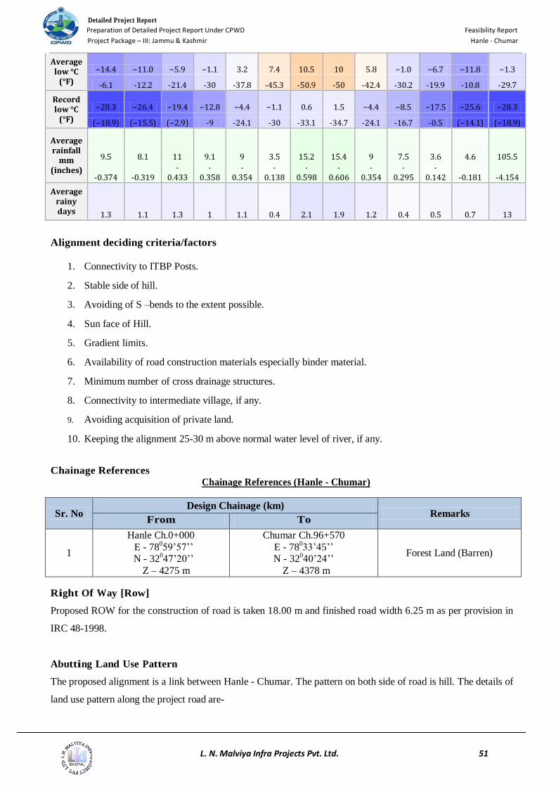
The below table shows the temperature record since 2007 as per climatological department of India.
Climate data for Leh (1951–1980)
Month Jan Feb Mar Apr May Jun Jul Aug Sep Oct Nov Dec Year
Record high °C
(°F)
8.3 12.8 19.4 23.9 28.9 34.8 34 34.2 30.6 25.6 20 12.8 34.8
-46.9 -55 -66.9 -75 -84 -94.6 -93.2 -93.6 -87.1 -78.1 -68 -55 -94.6
Average high °C
(°F)
−2.0 1.5 6.5 12.3 16.2 21.8 25 25.3 21.7 14.6 7.9 2.3 12.8
-28.4 -34.7 -43.7 -54.1 -61.2 -71.2 -77 -77.5 -71.1 -58.3 -46.2 -36.1 -55
Detailed Project Report Preparation of Detailed Project Report Under CPWD Feasibility Report
Project Package – III: Jammu & Kashmir Hanle - Chumar
L. N. Malviya Infra Projects Pvt. Ltd. 51
Average low °C
(°F)
−14.4 −11.0 −5.9 −1.1 3.2 7.4 10.5 10 5.8 −1.0 −6.7 −11.8 −1.3
-6.1 -12.2 -21.4 -30 -37.8 -45.3 -50.9 -50 -42.4 -30.2 -19.9 -10.8 -29.7
Record low °C
(°F)
−28.3 −26.4 −19.4 −12.8 −4.4 −1.1 0.6 1.5 −4.4 −8.5 −17.5 −25.6 −28.3
(−18.9) (−15.5) (−2.9) -9 -24.1 -30 -33.1 -34.7 -24.1 -16.7 -0.5 (−14.1) (−18.9)
Average rainfall
mm (inches)
9.5 8.1 11 9.1 9 3.5 15.2 15.4 9 7.5 3.6 4.6 105.5
-0.374 -0.319 -
0.433 -
0.358 -
0.354 -
0.138 -
0.598 -
0.606 -
0.354 -
0.295 -
0.142 -0.181 -4.154
Average rainy days 1.3 1.1 1.3 1 1.1 0.4 2.1 1.9 1.2 0.4 0.5 0.7 13
Alignment deciding criteria/factors
1. Connectivity to ITBP Posts.
2. Stable side of hill.
3. Avoiding of S –bends to the extent possible.
4. Sun face of Hill.
5. Gradient limits.
6. Availability of road construction materials especially binder material.
7. Minimum number of cross drainage structures.
8. Connectivity to intermediate village, if any.
9. Avoiding acquisition of private land.
10. Keeping the alignment 25-30 m above normal water level of river, if any.
Chainage References
Chainage References (Hanle - Chumar)
Sr. No Design Chainage (km)
Remarks From To
1
Hanle Ch.0+000
E - 78059’57’’
N - 32047’20’’
Z – 4275 m
Chumar Ch.96+570
E - 78033’45’’
N - 32040’24’’
Z – 4378 m
Forest Land (Barren)
Right Of Way [Row]
Proposed ROW for the construction of road is taken 18.00 m and finished road width 6.25 m as per provision in
IRC 48-1998.
Abutting Land Use Pattern
The proposed alignment is a link between Hanle - Chumar. The pattern on both side of road is hill. The details of
land use pattern along the project road are-

Detailed Project Report Preparation of Detailed Project Report Under CPWD Feasibility Report
Project Package – III: Jammu & Kashmir Hanle - Chumar
L. N. Malviya Infra Projects Pvt. Ltd. 52
Table: Existing Land Use Pattern ( Hanle - Chumar )
Terrain
The terrain is mountainous throughout the proposed alignment.
Important Settlements
There is no settlement/village/habitation along the alignment.
Traffic
The proposed road is entirely new proposal that has to be constructed and hence there is no traffic.
Pavement Compositions
As per clause no 10.22.3.1 of IRC: SP: 48- 1998, Hill road manual, In high altitude area which are subjected to
heavy snowfall, sub zero temperature, frost action, snow drifts and avalanche activities, design and construction of
pavement require special consideration.
The method of design followed is a modification of the CBR method incorporating mechanistic approach. The
empirical pavement design presented in IRC: 37-2012. "GUIDELINES FOR THE DESIGN OF FLEXIBLE
PAVEMENTS" (Second Revision) has been extended to cater design traffic up to 5 MSA using analytical design
method and has been followed for this project.
The traffic used in design is in terms of the cumulative number of standard axles to be carried during the design
life of the road.
As per clause no 10.22.3.5 of IRC: SP: 48- 1998, Hill road manual, depth of construction (pavement) should not be
less than depth of frost-penetration and should compose of non –frost suitable materials, In no case the thickness
should not be less than 450 mm.
Classification of terrain
Built up
Agriculture
Forest land (Barren)

Detailed Project Report Preparation of Detailed Project Report Under CPWD Feasibility Report
Project Package – III: Jammu & Kashmir Hanle - Chumar
L. N. Malviya Infra Projects Pvt. Ltd. 53
Accordingly, the field CBR evaluated from the samples collected from site during field survey at every 1.00 km
interval and traffic intensity has been considered as 5 MSA. However, as the alignment is intended to be used by
armed forces, and in case of emergencies, it is always better to have a crust with base layer sufficient to cater for
heavier loads. Accordingly, we have considered a crust thickness of 500 mm (200 mm GSB, 200 mm CRM, 60
mm DBM and 40 mm BC). This is as per ongoing Phase - I road works, which are on the same terrain, altitude
and geographic locations, where the recommendations of CRRI have been followed.
Further, as per clause no 1.5 and 2.1 of IRC: 37-2012, there is clearly mentioned that the local environment
and past pavement performance in the respective region must be considered, while selecting a pavement
thickness. Hence, as the proposed road mostly falls under snow prone area, the wearing course should be of
higher thickness. Further, due to unavailability of binder material, WMM or WBM can’t be feasible. So
based on the surrounding circumstances and availability of required construction material following
thickness of crust has been adopted.
Design of Pavement through IITPAVE
The design of the pavement has been checked with IITPAVE software as per IRC 37 - 2012 - Section 9 and the
results are as follows:
INPUTs:
SN Section Adopted MSA
Adopted CBR
(%)
Pavement Composition (mm)
BC
DBM
CRM
GSB
1 Hanle - Chumar 5 10% 40 60 200 200

Detailed Project Report Preparation of Detailed Project Report Under CPWD Feasibility Report
Project Package – III: Jammu & Kashmir Hanle - Chumar
L. N. Malviya Infra Projects Pvt. Ltd. 54
OUTPUT:
Further, the same has been done manually and the results are as follows:
Description Values Reference
Design Period 15 Years
Design Traffic for Bituminous layers (MSA) 5
Design Traffic for Base and Sub-base layers(MSA) 5
Effective CBR of Subgrade 10
Grade of Bitumen VG - 10
Pavement Crust (mm)
Granualar Subbase (GSB) 200 As per Crust
composition
considered
Crusher Run Macadam (CRM) 200
Dense Bituminous Macadam (DBM) 60
Bituminous Concete (BC) 40
Resilient Modulus in Mpa of
Subgrade 76.83 As per Eq. 5.2
Base course (CRM+GSB) 227.76 As per Eq. 7.1
Bituminous Layers (DBM & BC) 2000.00 As per Table 7.1
Poisson Ratio (μ) of
Subgrade 0.35 As per Table VIII -

Detailed Project Report Preparation of Detailed Project Report Under CPWD Feasibility Report
Project Package – III: Jammu & Kashmir Hanle - Chumar
L. N. Malviya Infra Projects Pvt. Ltd. 55
Description Values Reference
Base course (WMM+GSB) 0.35 I (Annexure - VIII)
Bituminous Layers (DBM & BC) 0.35
Allowable Strains
Horizontal tensile strain at the bottom of DBM layer (εt) 410.63E-06 As per Eq. 6.1
Vertical strain at top of subgrade (εv) 784.38E-06 As per Eq. 6.4
Computed strains from IITPAVE software
Horizontal tensile strain at the bottom of DBM layer (εt) 311.4 x 10⁻⁶
Vertical strain at top of subgrade (εv) 442.6 x 10⁻⁶
As the strains computed through IITPAVE are less than calculated strains as per IRC 37, the design is
SAFE.
Cross Drainage Works
Bridges/ Hume Pipe Culvert
There are total 183 no’s of Hume Pipe Culvert of following length that are being proposed in this alignment for
cross drainage works.
Bridges (1 x 40 m) - 3 No’s
Culverts - 380 No’s

Detailed Project Report Preparation of Detailed Project Report Under CPWD Feasibility Report
Project Package – III: Jammu & Kashmir Hanle - Chumar
L. N. Malviya Infra Projects Pvt. Ltd. 56
Design Parameters
Following design standards have been adopted as per Indian Roads Congress (IRC)
Guidelines, contained in IRC: 73, IRC: 86, IRC: 38 and IRC: SP: 23 and are given in Table
below:
Table- Design Parameters
Sl. No.
Item
Mountainous/Steep Terrain
1 Design speed (kmph) 30 Kmph, As per IRC:SP:48-1998, sub
clause 6.3.1
2 Right of Way 18.00 m
3 Width of carriageway (m) 3.75 m
4 Paved shoulders Nil
5 shoulders 2 x 1.25 m
6 Camber/cross fall
(i) Carriageway & paved shoulders 2.5%
(ii) Earthen shoulders 3.0%
7 Maximum super elevation 7%
8 Minimum Radii of horizontal curves (m) 30m Ruling /20m Absolute min.
9 Minimum length of vertical curves (m) 15 m
11 Drains As per Design
12 Sight Distance As per IRC:SP:23
13 Gradient
(i) Ruling Gradient 5%
(ii) Limiting Gradient 6%
(iii) Exceptional Gradient 7%

Detailed Project Report Preparation of Detailed Project Report Under CPWD Feasibility Report
Project Package – III: Jammu & Kashmir Hanle - Chumar
L. N. Malviya Infra Projects Pvt. Ltd. 57
Cost Estimate
The project cost derived is based on MoRT&H standard Date Book (2001 revision) duly
enhanced with 5% per annum and considering the effect of less labour output and reduced
efficiency of machinery and labour as per the altitudes of origin and destination points of road.
The Project road has been separated in item-wise sections and the bill wise total project cost is
tabulated in Table below
G E N E R A L S U M M A R Y O F C O S T
Sr.
No. Description of Sub-Head
Amount of items based on
Standard Data Book
published by MoRT&H (Rs.)
1 Earthworks 618,976,137
2 Sub Base & Base Course 1,320,998,772
3 Base and Surface Course (Bituminous) 481,484,377
4 Road appurtenances 29,516,143
5 Pipe culverts 56,353,917
6 Foundation of structures 173,246,693
7 Sub-structure 688,755,495
8 Bridge Works 59,313,551
9 Protection Works 498,455,349
Sub - Total A (Construction Works) 3,927,100,434
Civil Cost is Rs. 4.067 Crore Per km
10 Time required for Construction (years) after receipt of
statutory clearances and diversion of forest land 6
11 Amount of escalation after two (02) years @ 6.5% per
annum 1,021,046,113
Cost including escalation 4,948,146,547
12
Factor for managing cost elements, i.e. due to geological
surprises, hostile and unpredictable weather condition,
contingency plan for evacuation of labour, difficult terrain,
snow clearance and land slide clearance (Expedients) etc @
10% of A
392,710,043
13 Provision for Physical contingencies @ 3% of A 148,444,396
Grand Total 5,489,300,987
Construction Cost is Rs. 5.685 Crore Per km
14
Cost of maintenance yet to be finalized by MHA, hence no
provision has been kept in this estimate. Provision shall be
made after finalization of maintenance norms.
-
15 Cost of Land acquisition 166,251,130
Total cost including land acquisition 5,655,552,117

Detailed Project Report Preparation of Detailed Project Report Under CPWD Feasibility Report
Project Package – III: Jammu & Kashmir Hanle - Chumar
L. N. Malviya Infra Projects Pvt. Ltd. 58
SALIENT FEATURE
Description Proposed
Terrain : Mountainous
Length provided by ITBP : 75.00 Km
Designed Length 96.570 Km
Alignment : New Alignment
Design Speed : 30 kmph
Cross – Section : Flexible Pavement
Single-lane (Class 9 road)
0.6 m Drain + 1.25 m Shoulder + 3.75 m C/W + 1.25 m Shoulder + 0.6
m Extra Widening (On Curve Portion Only)
SN From To Length (km)
1 0 96.570 96.570
Total 96.570
CBR considered : 10%
Traffic : NIL
Pavement Design Life : 15 Years, As per IRC:SP:48-1998, Clause 10.6, Sub Clause 10.6.1
Design MSA : MSA – 5
Protection & Drainage Works
S.No. Description
1) Longitudinal Drains 96.37
2) Retaining wall 10520
3) Breast wall 7500
4) Max Fill depth 2.908
5) Max cutting depth 32.581
Pavement Crust Thickness for New construction
:
Flexible Pavement
Bituminous Concrete
Dense Bituminous Concrete
Crusher Run Macadam
Granular Sub Base
40 mm
60 mm
200 mm
200 mm
Total 500 mm
Hume Pipe Culvert : Total No’s of Hume Pipe Culvert: 185 No’s
1 x 1000 mm: 185 No’s
Bridges : Total No’s of Bridges : 3 No’s
1 x 40.000m : 3 No’s
ROW : Design has been done by considering ROW width of 18.00 m
Land to be acquired : 1,738,080Sqm
Total cost (Rs) Project : Rs. 5,489,300,987
Total Cost Including Land Acquisition : Rs. 5,655,552,117

Detailed Project Report Preparation of Detailed Project Report Under CPWD Feasibility Report
Project Package – III: Jammu & Kashmir Hanle - Chumar
L. N. Malviya Infra Projects Pvt. Ltd. 59
INTRODUCTION
General
Route Plan
From To Distance Approx Time for
Journey
Mode of Vehicle
Delhi Leh 1265 Km 24 Hrs By Road
Leh Hanle 261 Km 8 Hrs By Road
Total 1526 Km
Road Network of Jammu & Kashmir
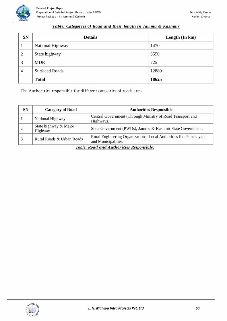
The following table shows the categories of road in Jammu &Kashmir and their length. It has a road network of
18625 km including un-surfaced village road to surfaced national highways, Jammu & Kashmir has 1470 km of
National Highway, 3550 km of State Highways, 725 km of Major District Roads and 12880 of Surfaced Roads.
Detailed Project Report Preparation of Detailed Project Report Under CPWD Feasibility Report
Project Package – III: Jammu & Kashmir Hanle - Chumar
L. N. Malviya Infra Projects Pvt. Ltd. 60
Table: Categories of Road and their length in Jammu & Kashmir
The Authorities responsible for different categories of roads are:-
Table: Road and Authorities Responsible.
SN Details Length (In km)
1 National Highway 1470
2 State highway 3550
3 MDR 725
4 Surfaced Roads 12880
Total 18625
SN Category of Road Authorities Responsible
1 National Highway Central Government (Through Ministry of Road Transport and
Highways.)
2 State highway & Major Highway
State Government (PWDs), Jammu & Kashmir State Government.
3 Rural Roads & Urban Roads Rural Engineering Organizations, Local Authorities like Panchayats and Municipalities.

Detailed Project Report Preparation of Detailed Project Report Under CPWD Feasibility Report
Project Package – III: Jammu & Kashmir Hanle - Chumar
L. N. Malviya Infra Projects Pvt. Ltd. 61
DESIGN STANDARDS
Design Criteria
The design criteria for the Project Road have been adopted with the objective of construction of new road. The
following guiding principles have been kept in view during evolving the highway designs:
Design Standards (Roads)
Terrain Classification
The project road under cover of this report lies wholly in mountainous terrain and the geometric standards relevant
to mountainous terrain as per IRC: SP: 48-1998 and IRC: 86-1983 have been adopted.
Guiding Standards for Highways
The design of various elements of highways is governed by the provisions of the following IRC Codes /
Guidelines / Manual.
IRC: SP: 48-1998 - Guidelines for Hill Road Manual
IRC: 56 -2012 – Recommended Practices for Treatment of Embankment and Roadside slopes for
Erosion control.
IRC: 38-1998 - Guidelines for Design of Horizontal Curves for Highways and Design Tables
IRC:66-1976 - Recommended Practice for Sight Distance in Rural Highways
IRC:67-2012 - Code of Practice for Road Signs (I Revision)
IRC: 73-1980 - Geometric Design Standards for Rural (Non-Urban) Highways.
IRC: 86-1983 - Geometric Design Standards for Urban Roads in Plains.
IRC:SP:23-1983 - Vertical curves for Highways
IRC:SP:44-1996 - Highways Safety Code
IRC:SP:19-2001- Manual for Survey, Investigation and Preparation of Road Projects
IS: 14458 (Part – I) – Retaining wall for Hill Area – Guidelines.
Manual for Safety in Road Design
Design Speed
Design speed depends on the function of the road as also the terrain conditions. It is the basic parameter which
determines all other geometric design features. Considering the practical problems associated with Land
acquisition and resettlement, the ruling and minimum design speed have been adopted at a lower value as shown
below. This has been done in line with the stipulations in IRC: SP: 48-1998.
The design speed shall be as under depending on site condition and other considerations:
Ruling Minimum

Detailed Project Report Preparation of Detailed Project Report Under CPWD Feasibility Report
Project Package – III: Jammu & Kashmir Hanle - Chumar
L. N. Malviya Infra Projects Pvt. Ltd. 62
Mountainous Terrain 30 km/hr 25 km/hr
Steep Terrain 25 km/hr 20 km/hr
If changes in the design speed appear unavoidable, gradual changes has been introduced by providing successive
sections of increasing / decreasing design speeds so that road users become progressively conditioned to such
changes.
Cross Sectional Elements
The guidelines based on IRC: SP: 48-1998 relevant to mountainous/steep terrain have been followed to finalize
various elements of roadway as detailed hereinafter.
Embankment side slope (Hill side) should normally be 1 (H): 1(V) and varying up to 1/8 (H): 1 (V) depending
upon the class of rock and stability of side slope. However, in case of Hard Rock cut may vary from 800-90
0 to
horizontal. Carriageway shall have cross-slope of 2.50%
The shoulders shall have a slope of 3.0% in super elevated sections the shoulders will have same cross fall as that
of the Pavement- The shoulders on high side of the super elevated portion shall be provided with reverse slope
from the super elevated carriageway portion.
Horizontal Alignment
Uniformity of design standards is one of the essential requirements of any road alignment. In a given section, there
must be consistent application of design criteria to avoid creation of unexpected situations for the drivers. As a
general rule, the horizontal alignment should be fluent and blend well with the surrounding topography.
Horizontal Curves
The horizontal curves for this project road have designed in accordance with the requirements as
stipulated in IRC: 38-1988. Horizontal curves will normally consist of a circular curve flanked by spiral
transition curves at both ends.
The transition curves have been facilitate gradual application of super-elevation and ensure smooth entry
of vehicles from straight to the circular curve without causing any discomfort to the driver.
Super elevation
Super elevation provided on horizontal curves based on the following formula:
e = V2/ 225R
Where, e = super elevation
V = speed (km/hr.)
R = radius (meter)
Super elevation as per IRC: SP: 48-1998, Clause 6.8.2 and Sub clause 6.8.2.2 and as obtained from the

Detailed Project Report Preparation of Detailed Project Report Under CPWD Feasibility Report
Project Package – III: Jammu & Kashmir Hanle - Chumar
L. N. Malviya Infra Projects Pvt. Ltd. 63
above expression is limited to the following values.
a. In snow bound areas 7%
b. In hilly areas not bound by snow 10%
Radius of Horizontal Curves
The radii of horizontal curves are calculated from the following formula:
R = V2/ 127(e + f)
Where, V = vehicle speed (km/hr.)
e = super elevation ratio (meter / meter)
f = coefficient of side friction between vehicle tyres and the pavement (taken as
0.15)
R = radius (meters).
Transition Curves
Transition curves are necessary for vehicles to progress smoothly from a straight alignment into a circular
curve or between curves of different radius. The transition curve also facilitates a gradual application of
the super elevation and any widening of the carriageway which may be required for the horizontal curves.
Spiral curves are used for this purpose.
The length of the transition curve is determined from the following two considerations, i.e. i) rate of
change of centrifugal acceleration, ii) rate of change of super elevation- The larger of the two values is
adopted for design:
0.0215 V3
Ls = CR
Where, Ls = length of transition in meters
V = speed in km/hr
R = radius of circular curve in meters
C = 7V-(maximum of 0.8 & minimum of 0.5)
Widening of Carriageway on Curves

Detailed Project Report Preparation of Detailed Project Report Under CPWD Feasibility Report
Project Package – III: Jammu & Kashmir Hanle - Chumar
L. N. Malviya Infra Projects Pvt. Ltd. 64
At sharp horizontal curves, it is necessary to widen the carriageway to Provide for safe Passage of
vehicles. The extra width of 0.6 m has been provided at horizontal curves.
Setback Distance at Horizontal Curves
Requisite sight distance is to be available across the inside of horizontal curves- The set-back distance
will be calculated from the following equation:
m = R- (R-n) Cos ø
Where, ø= S/ 2(r-n) radians
m = minimum set-back distance to sight obstruction in meters
R = radius at center line of road in meters
n = distance between the center line of the road and the center line of the inside lane in meters.
S = Sight distance in meters.
Where horizontal and summit vertical curves overlap, the design is Provide for required sight distance
both in vertical direction along the road and in the horizontal direction on the inside of the curve.
Vertical Alignment
Gradient
The vertical alignment is provided with a smooth longitudinal profile consistent with the terrain through
which the road passes. Gradients up to the "ruling gradient is used as far as Possible in the design. Grade
steeper than the "ruling gradient" is used for a length "as short as Possible".
Vertical Curve
Vertical curves are introduced for smooth transition at grade changes. For satisfactory appearance, the
minimum length of vertical curves is provided based on design speed as mentioned in IRC: 73 & IRC:
SP: 23.
Summit curves
The length of summit curve is governed by the choice of sight distance. The length of summit curve is
calculated for Intermediate sight distance unless there are site constraints when a safe stopping sight
distance is provided
For safe stopping sight distance
Case (I) when L>S
L = NS2/ 4.4
Where, N = Deviation angle Le. Algebraic difference between two grades.

Detailed Project Report Preparation of Detailed Project Report Under CPWD Feasibility Report
Project Package – III: Jammu & Kashmir Hanle - Chumar
L. N. Malviya Infra Projects Pvt. Ltd. 65
L = Length of parabolic vertical curve in meters
S= Sight distance in meters
Case (ii) when L<S
L = 2S – 4.4/N
For Intermediate sight distance
Case (i) when L>S
L = NS2 / 9.6
Case (ii) when L<S
L = 2S – 9.6/N
Valley Curves
Valley curves are designed for headlight sight distance.
Case (I) when L>S
I = NS2
1.50+0.035 S
Case (ii) when L<S
L = 2S – 1.50 + 0.035S
N
Sight Distance
On consideration of driver’s perception time & braking time required to control their vehicles to avoid
unwarranted accidents before meeting a stationary object in his path, proper sight distance will be required.
The various curves are designed corresponding to minimum Safe Stopping Sight Distance according to adopted
Design Speed as detailed below:
Stopping Slight Distance
Speed in Km/Hr. Safe Stopping Slight Distance
(meters)
Intermediate Sight Distance
(meters)
20 20 40
25 25 50
30 30 60
35 40 80
40 45 90
50 60 120
Pavement Design
General

Detailed Project Report Preparation of Detailed Project Report Under CPWD Feasibility Report
Project Package – III: Jammu & Kashmir Hanle - Chumar
L. N. Malviya Infra Projects Pvt. Ltd. 66
The pavement design activities include construction of single lane carriageway.
Design of Flexible Type Pavement Overlay
Not Applicable because no existing track available.
Design of Pavement for New Construction
Design of Flexible Pavement
Homogeneous Sections
Homogeneous sections for new construction have been adopted based on the type of founding
strata for embankment, sub-grade, height of embankment and traffic.
CBR of sub-grade / Module of Resilience of road bed soil.
Design Life
The design life for flexible pavement is 15 years according to IRC: SP: 48-1998. Clause 10.6.
Design Traffic
As this alignment is entirely new alignment and there is only a foot track is available, we have
adopted a MSA value of 5 in accordance with the bare minimum requirements stipulated in the
specification for new alignment published by Ministry of Road Transport & Highways.
Thickness of pavement layer
As there is no alignment existing, the traffic study cannot be conducted. As the alignment is
intended to be used by armed forces, and in case of emergencies, it is always better to have a
crust with base layer sufficient to cater for heavier loads. Accordingly, we have considered a
crust thickness of 500 mm (200 mm GSB, 200 mm CRM, 60 mm DBM and 40 mm BC). This is
as per ongoing Phase - I road works, which are on the same terrain, altitude and geographic
locations, where the recommendations of CRRI have been followed.
Miscellaneous Items
Traffic Signs
To ensure safe and efficient flow of traffic in the high speed project corridor, traffic must be regulated through a
system guidance and control systems. Accordingly traffic signs, of retro- reflective types, as per IRC: 67:2012 is
provided as follows:-
Mandatory/Regulating signs (violation of which is legal offence) e.g. stop signs, speed limits etc.
Warning / Cautionary signs to warn the road users of existence of certain restrictions / hazardous
conditions.
Informatory signs e.g. distance information boards directions signs, route number etc.

Detailed Project Report Preparation of Detailed Project Report Under CPWD Feasibility Report
Project Package – III: Jammu & Kashmir Hanle - Chumar
L. N. Malviya Infra Projects Pvt. Ltd. 67
Kilometer Stones
Kilometer stones are provided along the road on the left side as follows:-
i. 5th kilometer stones as per IRC: 8-1980.
ii. Kilometer stone as per IRC: 8-1980.
iii. Hectometer stone as per IRC: 26-1967.
Delineator
Road delineators are provided as visual aids for safety at night as per IRC 79-1981 for the horizontal curves.
Traffic Safety Measures
RCC Retaining walls are provided along the edges of formation on unstable slopes on hill side and valley side and
sharp horizontal curves to prevent vehicles accidentally leaving the highway as per relevant IRC specification.
Cost Estimate and Specification
The detailed estimated cost for the road section has been prepared on estimation of quantities from the detailed
design and drawings. The rates for the individual items have been adopted based on the prevailing market rates.
Detailed Project Report Preparation of Detailed Project Report Under CPWD Feasibility Report
Project Package – III: Jammu & Kashmir Hanle - Chumar
L. N. Malviya Infra Projects Pvt. Ltd. 68
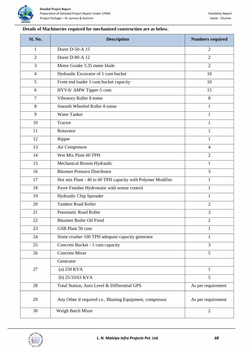
Details of Machineries required for mechanized construction are as below.
Sl. No. Description Numbers required
1 Dozer D-50-A 15 2
2 Dozer D-80-A 12 2
3 Motor Grader 3.35 meter blade 2
4 Hydraulic Excavator of 1 cum bucket 10
5 Front end loader 1 cum bucket capacity 10
6 HYVA/ AMW Tipper-5 cum 15
7 Vibratory Roller 8 tonne 8
8 Smooth Wheeled Roller 8 tonne 1
9 Water Tanker 1
10 Tractor 1
11 Rotavator 1
12 Ripper 1
13 Air Compressor 4
14 Wet Mix Plant 60 TPH 2
15 Mechanical Broom Hydraulic 1
16 Bitumen Pressure Distributor 3
17 Hot mix Plant - 40 to 60 TPH capacity with Polymer Modifier 1
18 Paver Finisher Hydrostatic with sensor control 1
19 Hydraulic Chip Spreader 1
20 Tandem Road Roller 2
21 Pneumatic Road Roller 3
22 Bitumen Boiler Oil Fired 2
23 GSB Plant 50 cum 1
24 Stone crusher 100 TPH adequate capacity generator 1
25 Concrete Bucket - 1 cum capacity 3
26 Concrete Mixer 5
27
Generator
(a) 250 KVA 1
(b) 25/33/63 KVA 5
28 Total Station, Auto Level & Differential GPS As per requirement
29 Any Other if required i.e., Blasting Equipment, compressor As per requirement
30 Weigh Batch Mixer 2

Detailed Project Report Preparation of Detailed Project Report Under CPWD Feasibility Report
Project Package – III: Jammu & Kashmir Hanle - Chumar
L. N. Malviya Infra Projects Pvt. Ltd. 69
CONCLUSIONS AND RECOMMENDATIONS
Conclusions
The project road Hanle - Chumar falls in the state of Jammu & Kashmir.
The terrain is mountainous and has steep gradients.
The proposed Length of Project road is 96.570 km.
The total cost of the project is Rs. 5,655,552,117.
The project has been proposed for implementation in single construction package.
It is proposed that duration for completion of whole project shall be 6 years including non working
period.
The proposed road is a new construction, environmental impacts are anticipated during the
construction therefore environmental clearance should be obtained before the construction of the
project.
Recommendations
The design Length of Project road is 96.570 km.
The Project road is proposed as Single lane with shoulder, drain, extra widening (3.75m + 2 x 1.25m
+ 0.6 m + 0.6m).
Proposed ROW is taken 18.00 m areas as per provision in IRC: SP: 48-1998.
The Pavement of Project road is proposed only as flexible pavement.
The Crust is designed on basis of 5 MSA and as per ongoing phase – I work.
Crust is -
BC 40 mm
DBM 60 mm
CRM 200 mm
GSB 200 mm
The horizontal & vertical improvements are proposed as per site requirements.
EIA study should be done and EMP for mitigation measures should be implemented during
construction.
The alignment protection measures including Breast walls, crash barriers etc and cross drainage works
have been considered as per present site condition. After formation cutting, some technical improvements
may be required. These shall be incorporated at that stage.