Feasibility of a magnetic suspension for second generation Gravitational Wave · PDF...
21
arXiv:physics/0401163v1 [physics.ins-det] 29 Jan 2004 Feasibility of a magnetic suspension for second generation Gravitational Wave interferometers Monica Varvella a,* , Enrico Calloni a , Luciano Di Fiore a , Leopoldo Milano a , Nicolas Arnaud b a Istituto Nazionale di Fisica Nucleare, Sez. di Napoli, Universit´a degli Studi di Napoli ”Federico II”(Na), Italy. b Laboratoire de l’Acc´ el´ erateur Lin´ eaire, CNRS-IN2P3 and Universit´ e Paris Sud, B.P. 34, Bˆatiment 200, Campus d’Orsay, 91898 Orsay Cedex (France). Abstract This paper deals with the use of a magnetic levitation system as a part of a multi-stage seismic attenuator for gravitational wave interferometric antennas. The proposed configuration uses permanent magnets in attraction to balance the sus- pended weight, plus a closed loop position control to obtain a stable levitation. The system is analyzed using a MATLAB simulation code to compute the forces exerted by extended magnets. The validity of this model has been tested by a comparison with the experimental data from a levitated suspension prototype. Key words: gravitational waves, magnetic levitation, suspended interferometer, Virgo superattenuator, control systems PACS: 04.80.Nn, 07.05.Dz, 07.60.Ly 1 Introduction Magnetic levitation systems find several applications [1,2,3,4] in physics and engineering, ranging from small force measurements to transportation systems. In this paper, we analyze the possibility of using magnetic levitation as a future * Corresponding author. Email address: [email protected] (Monica Varvella). Preprint submitted to Astroparticle Physics 9 April 2018
Transcript of Feasibility of a magnetic suspension for second generation Gravitational Wave · PDF...
arX
iv:p
hysi
cs/0
4011
63v1
[ph
ysic
s.in
s-de
t] 2
9 Ja
n 20
04
Feasibility of a magnetic suspension for second
generation Gravitational Wave
interferometers
Monica Varvella a,∗, Enrico Calloni a, Luciano Di Fiore a,Leopoldo Milano a, Nicolas Arnaud b
aIstituto Nazionale di Fisica Nucleare, Sez. di Napoli, Universita degli Studi diNapoli ”Federico II”(Na), Italy.
bLaboratoire de l’Accelerateur Lineaire, CNRS-IN2P3 and Universite Paris Sud,B.P. 34, Batiment 200, Campus d’Orsay, 91898 Orsay Cedex (France).
Abstract
This paper deals with the use of a magnetic levitation system as a part of amulti-stage seismic attenuator for gravitational wave interferometric antennas. Theproposed configuration uses permanent magnets in attraction to balance the sus-pended weight, plus a closed loop position control to obtain a stable levitation. Thesystem is analyzed using a MATLAB simulation code to compute the forces exertedby extended magnets. The validity of this model has been tested by a comparisonwith the experimental data from a levitated suspension prototype.
Key words: gravitational waves, magnetic levitation, suspended interferometer,Virgo superattenuator, control systemsPACS: 04.80.Nn, 07.05.Dz, 07.60.Ly
1 Introduction
Magnetic levitation systems find several applications [1,2,3,4] in physics andengineering, ranging from small force measurements to transportation systems.In this paper, we analyze the possibility of using magnetic levitation as a future
∗ Corresponding author.Email address: [email protected] (Monica Varvella).
Preprint submitted to Astroparticle Physics 9 April 2018
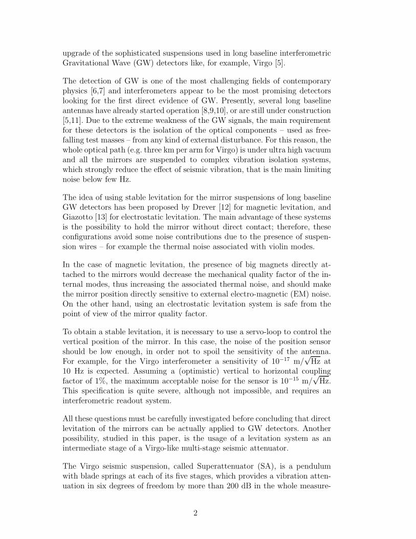
upgrade of the sophisticated suspensions used in long baseline interferometricGravitational Wave (GW) detectors like, for example, Virgo [5].
The detection of GW is one of the most challenging fields of contemporaryphysics [6,7] and interferometers appear to be the most promising detectorslooking for the first direct evidence of GW. Presently, several long baselineantennas have already started operation [8,9,10], or are still under construction[5,11]. Due to the extreme weakness of the GW signals, the main requirementfor these detectors is the isolation of the optical components – used as free-falling test masses – from any kind of external disturbance. For this reason, thewhole optical path (e.g. three km per arm for Virgo) is under ultra high vacuumand all the mirrors are suspended to complex vibration isolation systems,which strongly reduce the effect of seismic vibration, that is the main limitingnoise below few Hz.
The idea of using stable levitation for the mirror suspensions of long baselineGW detectors has been proposed by Drever [12] for magnetic levitation, andGiazotto [13] for electrostatic levitation. The main advantage of these systemsis the possibility to hold the mirror without direct contact; therefore, theseconfigurations avoid some noise contributions due to the presence of suspen-sion wires – for example the thermal noise associated with violin modes.
In the case of magnetic levitation, the presence of big magnets directly at-tached to the mirrors would decrease the mechanical quality factor of the in-ternal modes, thus increasing the associated thermal noise, and should makethe mirror position directly sensitive to external electro-magnetic (EM) noise.On the other hand, using an electrostatic levitation system is safe from thepoint of view of the mirror quality factor.
To obtain a stable levitation, it is necessary to use a servo-loop to control thevertical position of the mirror. In this case, the noise of the position sensorshould be low enough, in order not to spoil the sensitivity of the antenna.For example, for the Virgo interferometer a sensitivity of 10−17 m/
√Hz at
10 Hz is expected. Assuming a (optimistic) vertical to horizontal couplingfactor of 1%, the maximum acceptable noise for the sensor is 10−15 m/
√Hz.
This specification is quite severe, although not impossible, and requires aninterferometric readout system.
All these questions must be carefully investigated before concluding that directlevitation of the mirrors can be actually applied to GW detectors. Anotherpossibility, studied in this paper, is the usage of a levitation system as anintermediate stage of a Virgo-like multi-stage seismic attenuator.
The Virgo seismic suspension, called Superattenuator (SA), is a pendulumwith blade springs at each of its five stages, which provides a vibration atten-uation in six degrees of freedom by more than 200 dB in the whole measure-
2
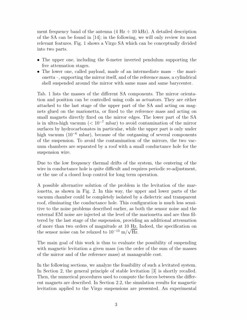
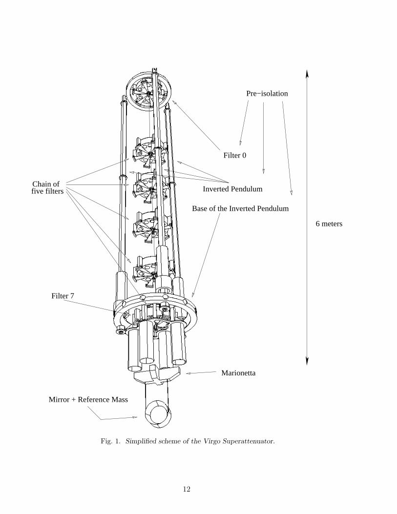
ment frequency band of the antenna (4 Hz ÷ 10 kHz). A detailed descriptionof the SA can be found in [14]; in the following, we will only review its mostrelevant features. Fig. 1 shows a Virgo SA which can be conceptually dividedinto two parts.
• The upper one, including the 6-meter inverted pendulum supporting thefive attenuation stages.
• The lower one, called payload, made of an intermediate mass – the mari-
onetta –, supporting the mirror itself, and of the reference mass, a cylindricalshell suspended around the mirror with same mass and same barycenter.
Tab. 1 lists the masses of the different SA components. The mirror orienta-tion and position can be controlled using coils as actuators. They are eitherattached to the last stage of the upper part of the SA and acting on mag-nets glued on the marionetta, or fixed to the reference mass and acting onsmall magnets directly fixed on the mirror edges. The lower part of the SAis in ultra-high vacuum (< 10−7 mbar) to avoid contamination of the mirrorsurfaces by hydrocarbonates in particular, while the upper part is only underhigh vacuum (10−6 mbar), because of the outgassing of several componentsof the suspension. To avoid the contamination of the mirrors, the two vac-uum chambers are separated by a roof with a small conductance hole for thesuspension wire.
Due to the low frequency thermal drifts of the system, the centering of thewire in conductance hole is quite difficult and requires periodic re-adjustment,or the use of a closed loop control for long term operation.
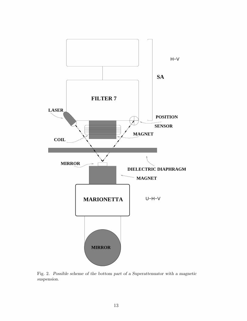
A possible alternative solution of the problem is the levitation of the mar-
ionetta, as shown in Fig. 2. In this way, the upper and lower parts of thevacuum chamber could be completely isolated by a dielectric and transparentroof, eliminating the conductance hole. This configuration is much less sensi-tive to the noise problems described earlier, as both the sensor noise and theexternal EM noise are injected at the level of the marionetta and are thus fil-tered by the last stage of the suspension, providing an additional attenuationof more than two orders of magnitude at 10 Hz. Indeed, the specification onthe sensor noise can be relaxed to 10−13 m/
√Hz.
The main goal of this work is thus to evaluate the possibility of suspendingwith magnetic levitation a given mass (on the order of the sum of the massesof the mirror and of the reference mass) at manageable cost.
In the following sections, we analyze the feasibility of such a levitated system.In Section 2, the general principle of stable levitation [3] is shortly recalled.Then, the numerical procedures used to compute the forces between the differ-ent magnets are described. In Section 2.2, the simulation results for magneticlevitation applied to the Virgo suspensions are presented. An experimental
3
test – described in Section 2.3 – shows the feasibility of the magnetic levi-tation; the experimental results obtained on a small levitated suspension arecompared with the predictions of some numerical simulations in order to checkthe validity of the model.
2 Magnetic suspension system
As it is well known, a stable levitation in a constant magnetic field can beobtained only with superconducting and diamagnetic materials [1,2,3,4]. Us-ing superconducting materials requires low temperature operation; thus, theirintegration in the seismic suspension of GW detectors looks complex and ex-pensive. Moreover, for diamagnetic materials, levitating very small pieces re-quires intense fields, which makes the suspension of a payload of several tensof kilograms (see Tab. 1) almost impossible. On the other hand, using a mag-netic field of variable intensity controlled by a feedback system in associationwith permanent magnets and electromagnets is more promising.
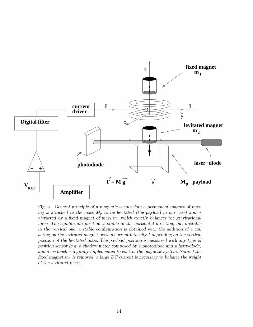
The general principle of such device can be seen in Fig. 2 and 3: a permanentmagnet of mass m2 is attached to the mass to be levitated (for the Virgo SA,the payload and the mirror) and is attracted by a fixed magnet of mass m1
(on the SA upper part) which exactly balances the gravitational force. In thisconfiguration, the equilibrium position is stable in the horizontal direction,but unstable in the vertical one. This configuration can become stable if a coilacting on the levitated magnet is added, with a current intensity I dependingon the vertical position of the levitated mass. This position can be measuredwith any type of position sensor (a shadow meter for our experiment, seeSection 2.3). In principle, the fixed magnet m1 could be removed, but in thiscase, a large DC current would be necessary to balance the weight of thelevitated piece.
2.1 The numerical simulation
Testing the feasibility of such technique is not enough, as one cannot simplyscale a system made of point-like magnets to a large device using extendedmagnets, such as the one needed for a Virgo SA: the dipole approximation is nomore valid to compute the magnetic force. Therefore, an accurate calculationof the forces between the fixed and the levitated magnets is needed.
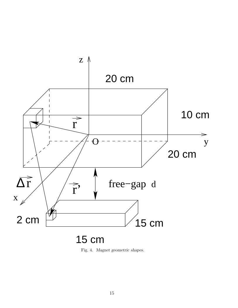
Numerically, the magnetic field generated by a couple of big magnets is com-puted by dividing the large pieces into infinitesimal volumes, as shown inFig. 4. Using the corresponding magnetization per unit volume, it is possible
4
to apply the dipole approximation between any two such small regions (one ineach magnet), provided that their separation is much larger than their sizes.The final force is the sum of all these infinitesimal contributions. For instance,in Fig.4, the vector ~r gives the position of an infinitesimal volume of the fixedmagnet (with respect to the origin O of the reference system, chosen at the
center of the fixed magnet), while−→r′ points on the levitated magnet. ∆~r is
defined as the separation vector between the two considered volumes.
The computation of the forces between extended magnets has been imple-mented in MATLAB [16]. The main aim of this tool is to study the bestconfiguration, by changing the dimensions of the two magnets and their sepa-ration. Of course, the accuracy of the computation depends on the dimensionsof the infinitesimal volume adopted for the simulation. In each computation,they have been reduced iteratively until convergence (within 2%). In our nu-merical code, the shape, the size and the separation of the magnets are freeparameters; for simplicity, we use parallelepipedal magnets.
2.2 Simulation results
For a given geometrical configuration, the force between the magnets dependson the residual magnetization Br, a magnet proper parameter. For our com-putation, we use Nd-Fe-B magnets which have currently the higher residualmagnetization (Br = 1.3 T); the density of this material is ρ = 7.4 g/cm3.For each magnet, the dimensions to be optimized are the length, that is thesize of the rectangular parallelepiped in the direction the optical axis of thesuspended mirror, the width, defined as the size along the transfer dimensionand the vertical thickness.
The goal of our study is to determine how the static force between the fixedand the levitated magnet changes with their sizes and their separation. Inparticular, we use as parameter the ‘free-gap’ d, i.e. the distance between thetwo magnets. In this way, we can evaluate the maximum mass that can belevitated in each configuration. In all cases, we need to subtract to the totallevitated mass M the weight of the levitated magnet m, so that we get theeffective payload (mirror + marionetta) mass Mp.
Another subject studied here is the dependence of the mass to be suspendedand of the horizontal restoring force on the length and the width of the mag-nets. This allows us to study the performance of the levitated system as aseismic isolator [12].
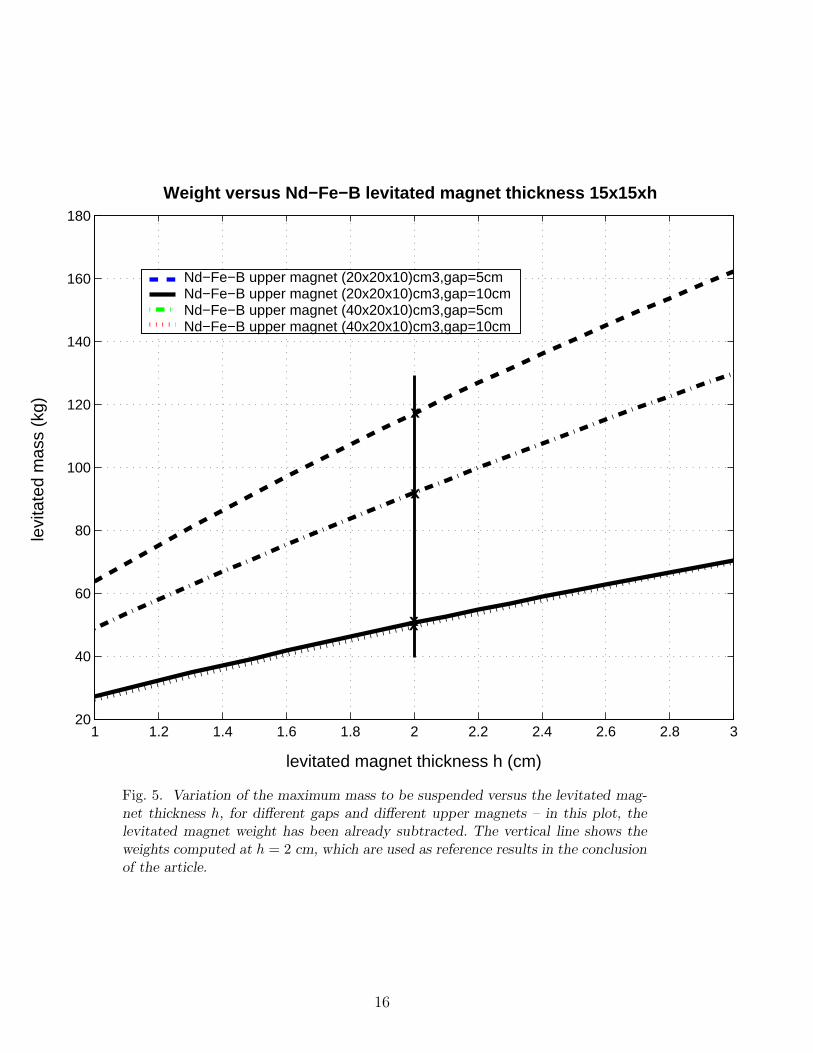
The first simulation aims at evaluating the maximum weight of the levitatedmass Mp as a function of the levitated magnet thickness h. Fig. 5 shows
5
the result: the simulation has been done for two different “free-gap” values(d = 5 cm and d = 10 cm) and for two different upper magnet configurations:(20× 20× 10) cm3 and (40× 20× 10) cm3. The levitated magnet dimensionsare (15× 15× h) cm3.
For instance, when the thickness of the levitated magnet to be h = 2 cm,it is possible to suspend about 50 kg when the free-gap is 10 cm and forupper magnet dimensions of (20× 20× 10) cm3. As we can see in Fig. 5, themaximum mass to be suspended increases with the thickness and of coursestrongly depends on the free-gap. An interesting point, apparently counter-intuitive, is that for given values of h and d, the force is smaller for the uppermagnet with the larger lateral size. This aspect will be clarified later.
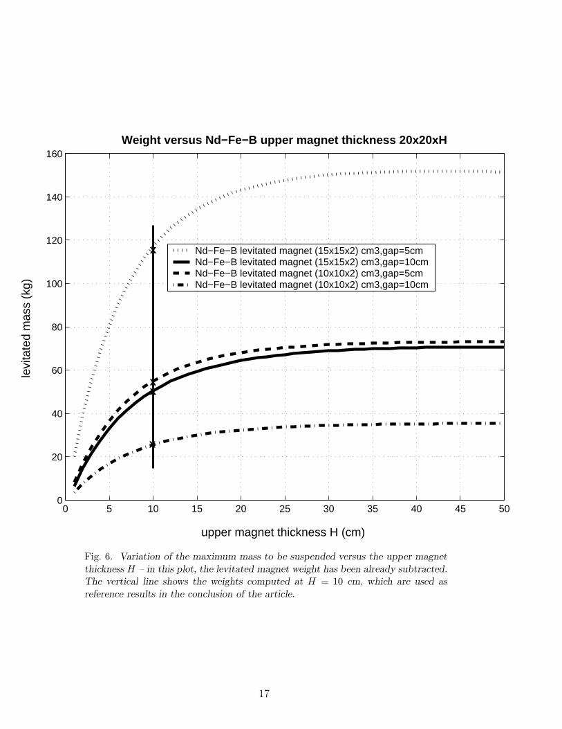
The second step is to evaluate the dependence of Mp on the upper magnetthickness H. The result is shown in Fig. 6: simulations have been done fortwo free-gap values already considered and for two different levitated magnetconfigurations: the first one, with dimensions (15 × 15 × 2) cm3 and massMm ∼ 3.3 kg and the second one, with dimensions (10 × 10 × 2) cm3 andmass Mm ∼ 1.5 kg; the upper magnet dimensions are (20 × 20 × H) cm3.We can see that it is possible to obtain a levitated mass of 120.5 kg in theconfiguration (15× 15× 2) cm3 and with a gap of 5 cm: as a cross-check, thisvalue corresponds to the one found in Fig. 5 with the same configuration.
Looking at Fig. 6, we can see that it is almost useless to increase the thicknessH above 30÷40 cm because the force becomes almost constant. As expected,there is still a strong dependence on the gap; for example, we obtain almostthe same force with a much smaller suspended magnet, by reducing d from10 cm to 5 cm.
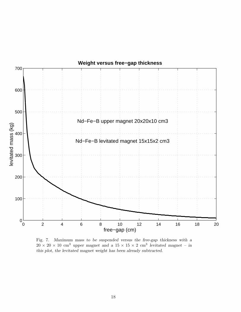
The third simulation studies the evolution of the levitated mass Mp when thefree-gap d varies, as Fig. 7 shows; the upper magnet dimensions are, in thiscase, (20× 20× 10) cm3 and the levitated ones (15× 15× 2) cm3. Of course,the suspendable mass value decreases with the increase of the free-gap.
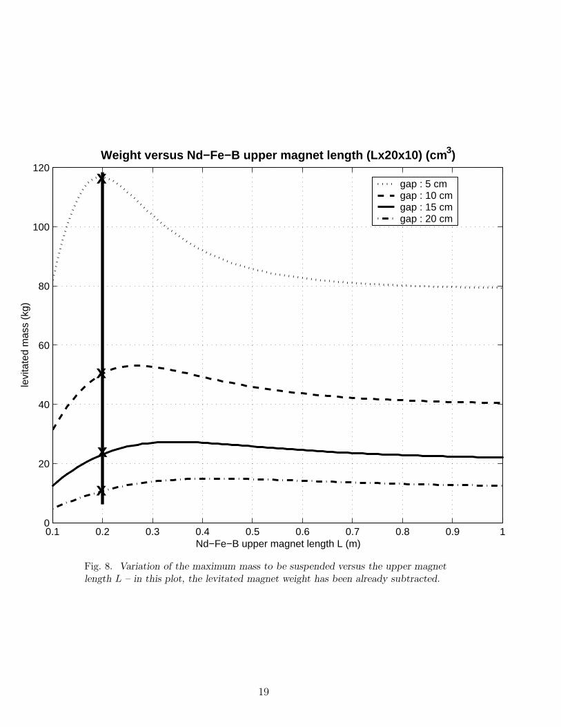
The variation of the suspendable mass Mp versus the length L of the uppermagnet is the topic of the fourth simulation. As shown in Fig. 8, the calculationhas been done for a set of different free-gap values ranging from d = 5 cmto d = 20 cm. The dimensions of the magnets are (L × 20 × 10) cm3 forthe upper one and (15 × 15 × 2) cm3 for the levitated one. As we can seefrom the Figure, using an upper magnet too long with respect to the free-gap dimension is not an advantage, because the force crosses a maximum andthen decreases asymptotically to a constant value. This effect has been alreadyobserved in Fig 5. It can be easily explained by noting that the force alongthe magnetic dipole direction changes its sign when the transverse distance ofthe two dipoles becomes much larger than their longitudinal one.
6
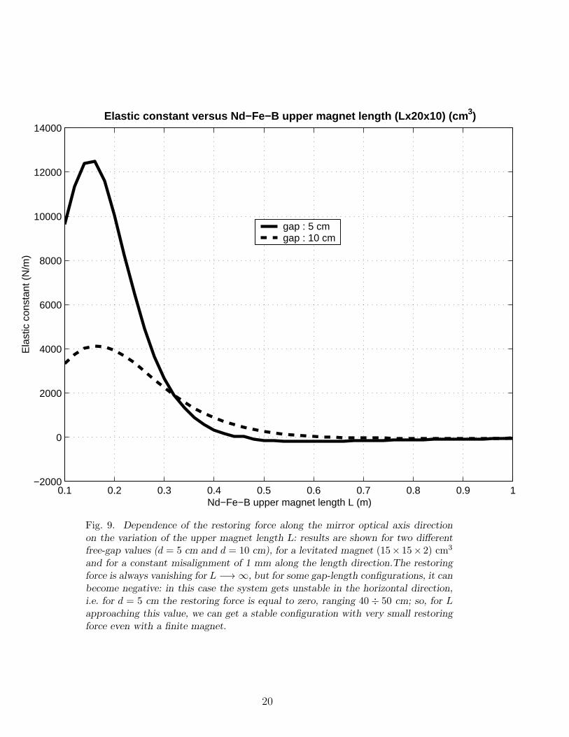
The last investigated point is the dependence of the restoring force along themirror optical axis direction on the variation of the upper magnet length L.This calculation has been done for different free-gap values, d = 5 cm andd = 20 cm, for a levitated magnet (15 × 15 × 2) cm3 and for a constant‘misalignment’ of 1 mm along the length direction, as shown in Fig. 9. As wecan see, the restoring force is always vanishing for L −→ ∞; in this case, asproposed by Drever [12], the system behaves like a pendulum with a very lowresonant frequency, i.e. it is in principle a very good seismic isolator.
The interesting point is that, for some gap-length configurations, the restoringforce can become negative: in this case the system gets unstable in the hori-zontal direction. As a consequence, there is a finite length giving a restoringforce equal to zero, ranging 40÷ 50 cm. So, for L approaching this value, wecan get a stable configuration with very small restoring force even with a finitemagnet. For example, if we take a magnet with L = 40 cm, with d = 5 cmwe can levitate up to ∼ 95 kg (see Fig. 9) with an horizontal restoring forceof only 200 N/m, corresponding to a resonant frequency of ∼ 0.23 Hz: thisis the equivalent of a 45 m-long pendulum. As a comparison, the SA mainresonance frequency is around 30 mHz which is equivalent to a 275 m-longsimple pendulum.
2.3 Experimental test
A magnetic suspension prototype has been realized in Naples [15] to checkthe correctness of our models and to verify that we take into account all therelevant effects. Our set-up is sketched in Fig. 3; we use Sm-Co cylindricalmagnets which have a residual magnetization Br = 0.8 T and a density ρ =8.3 g/cm3. The radius is R = 7 mm while the thickness is h = 12 mm for thefixed magnet and 8 mm for the levitated one with a mass m of about 10 g. Tomeasure the vertical position of the payload, we use a shadow-meter sensormade of a laser diode partially intersected by the payload lower edge and aphotodetector. To get a stable position we feedback on a coil acting on thelevitated magnet with a force/current characteristic of about 1 N/A. In thisway we are able to hold constant the vertical position of the payload respectto the ground. Using this configuration it is possible to suspend a payload ofabout 45 g with a free-gap ranging between 1 and 3 cm. The ‘fixed’ magnetis mounted on a micrometric translator allowing to change the free-gap andconsequently the vertical force between the magnets. When this force exactlybalanced the total weight of the suspended body, the DC current flowing inthe coil is zero. The changing of the vertical distance of the magnets withthe micrometer results in a non-zero DC current because the force exerted bythe coil must balance the difference between the weight and magnets forces.In this way, the current flowing in the coil provides a measurement of the
7
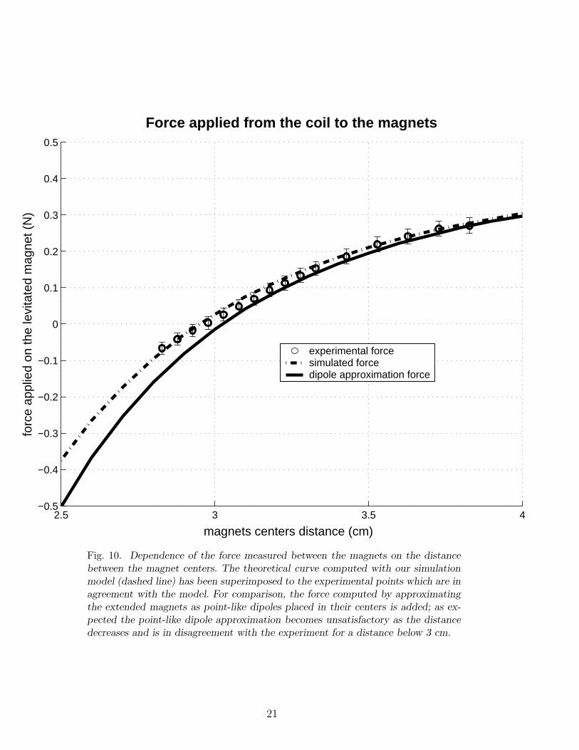
force between the magnets (subtracted of the weight of the suspended mass).Fig. 10 shows the dependence of the measured force between the magnetson the distance between the centers of the magnets. The theoretical curvecomputed with our simulation model (dashed line) is superimposed to theexperimental points. As we can see, the experimental points are in agreementwith the model. For comparison, we add the force computed by approximatingthe extended magnets as point-like dipoles placed in their centers; as expected,the point-like dipole approximation becomes unsatisfactory as the distancedecreases and disagrees with the experiment for a distance below 3 cm.
3 Conclusion
In this paper we studied the application of a magnetic levitation system tothe seismic suspensions of long baseline GW antennas. From the results of thesimulations shown in Sec. 2.2, we can summarize the following conclusions.
First, it appears that it is possible to levitate a mass comparable to the oneof a Virgo-like payload, choosing reasonable dimensions for both the fixedand levitated magnet. This can also be done maintaining a free-gap of severalcentimeters, which would allow the insertion of a dielectric roof to separatethe upper and the lower vacuum chambers.
A second interesting point is that, with a suitable magnet arrangement, thelevitated system behaves also as a low frequency seismic attenuator, which im-proves thus the overall attenuation performance of the suspension. To improvethe stability of the device, a pair of magnets aligned with opposing polaritycan be used instead of a single one, as first suggested in Ref. [12]. This con-figuration was validated experimentally in the Naples Virgo laboratory [15].
To give an example, we can consider as convenient configuration a fixed magnetof (40×20×10) cm3, a levitated one of (15×15×2) cm3 and a gap d = 5 cm.In this configuration, the weights of the two magnets are 66.4 kg and 3.3 kgrespectively, while the levitated payload Mp is ∼ 95 kg. As explained before,the horizontal oscillation frequency is, in this case, 0.23 Hz, giving an extraattenuation of about 74 db at 10 Hz.
The validity of the numerical model adopted for computing forces exertedbetween extended magnets has been experimentally tested with a small pro-totype suspension. The experimental results are in good agreement with themodel. Of course, the study presented here only shows the feasibility of theprinciple; one of the main limitation is that we did not consider the couplingwith the angular degrees of freedom of the suspended payload. A detailedstudy would be necessary to design a real suspension taking into account the
8

need of controlling the other degrees of freedom of the mirror and other tech-nical aspects, like the longitudinal control and the automatic alignment ofthe interferometer. In addition, a suspension designed for GW interferometersmust not inject too many noise in the detector. Therefore, noise contributionsoriginating from the magnetic configuration itself – like eddy and Johnsoncurrent effects – have to be taken into account on a full-scale prototype to seewhether or not they limit the suspension performances. This is beyond thegoal of this paper.
9
References
[1] E. H. Brandt, Levitation in Physics, Science 243, 349 (January 1989) andPhysics World (September 1997).
[2] A. Geim, Everyone’s Magnetism, Physics Today (September 1998).
[3] B. V. Jayawant, Electromagnetic suspension and levitation, Rep. Prog. Phys.vol. 44 (1981).
[4] D. Jiles, Introduction to magnetism and magnetic materials, Chapman & Hall(1991).
[5] http://www.virgo.infn.it/
[6] D. G. Blair, The detection of gravitational waves, Cambridge : Cambridgeuniversity press (1991) - XXIV.
[7] P. R. Saulson, Interferometric gravitational wave detectors”, World ScientificPublishing (1994).
[8] http://www.ligo.caltech.edu/
[9] http://tamago.mtk.nao.ac.jp/
[10] http://www.geo600.uni-hannover.de/
[11] http://www.anu.edu.au/Physics/ACIGA/
[12] R. W. P. Drever, Techniques for extending interferometer performance usingmagnetic levitation and other methods, Proceedings of the InternationalConference on Gravitational Waves (Source and Detectors), Eds I.Ciufolini -F.Fidecaro World Scientific (March 1996).
[13] A. Giazotto, Physics Letters A 245, 203-208 (1998).
[14] G. Ballardin, et al., Rev. Sci. Instrum. 72, 3643 (2001).
[15] M. Varvella, Sospensione magnetica per un interferometro per la rivelazione dionde gravitazionali; Degree Thesis, Napoli (1999).Available on the web at the URLhttp://www.infn.it/thesis/PS/340-Varvella-laurea.ps
[16] http://www.mathworks.com/products/matlab/
10
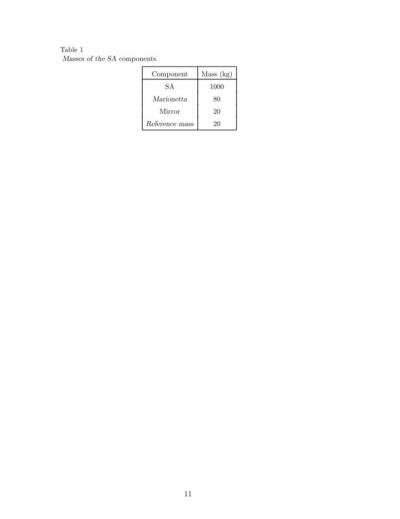
Table 1Masses of the SA components.
Component Mass (kg)
SA 1000
Marionetta 80
Mirror 20
Reference mass 20
11
6 meters
Filter 0
Chain of
Marionetta
five filters
Filter 7
Mirror + Reference Mass
Base of the Inverted Pendulum
Inverted Pendulum
Pre−isolation
Fig. 1. Simplified scheme of the Virgo Superattenuator.
12
MAGNET
MAGNET
MIRROR
MIRROR
FILTER 7
SA
MARIONETTA U−H−V
H−V
DIELECTRIC DIAPHRAGM
COIL
LASER
POSITION
SENSOR
Fig. 2. Possible scheme of the bottom part of a Superattenuator with a magneticsuspension.
13
Amplifier
drivercurrent
+−
Digital filter
VREF
levitated magnet
1
fixed magnet
Mp payload
2m
m
F = M g
OI I
xy
z
photodiode laser−diode
Fig. 3. General principle of a magnetic suspension: a permanent magnet of massm2 is attached to the mass Mp to be levitated (the payload in our case) and isattracted by a fixed magnet of mass m1 which exactly balances the gravitationalforce. The equilibrium position is stable in the horizontal direction, but unstablein the vertical one; a stable configuration is obtained with the addition of a coilacting on the levitated magnet, with a current intensity I depending on the verticalposition of the levitated mass. The payload position is measured with any type ofposition sensor (e.g. a shadow meter composed by a photodiode and a laser-diode)and a feedback is digitally implemented to control the magnetic system. Note: if thefixed magnet m1 is removed, a large DC current is necessary to balance the weightof the levitated piece.
14
r
r’∆ r
20 cmO
10 cm
20 cm
15 cm
15 cm2 cm
y
z
x
free−gapd
Fig. 4. Magnet geometric shapes.
15
1 1.2 1.4 1.6 1.8 2 2.2 2.4 2.6 2.8 320
40
60
80
100
120
140
160
180
Weight versus Nd−Fe−B levitated magnet thickness 15x15xh
levitated magnet thickness h (cm)
levi
tate
d m
ass
(kg)
Nd−Fe−B upper magnet (20x20x10)cm3,gap=5cmNd−Fe−B upper magnet (20x20x10)cm3,gap=10cm Nd−Fe−B upper magnet (40x20x10)cm3,gap=5cmNd−Fe−B upper magnet (40x20x10)cm3,gap=10cm
x
x
x
x
Fig. 5. Variation of the maximum mass to be suspended versus the levitated mag-net thickness h, for different gaps and different upper magnets – in this plot, thelevitated magnet weight has been already subtracted. The vertical line shows theweights computed at h = 2 cm, which are used as reference results in the conclusionof the article.
16
0 5 10 15 20 25 30 35 40 45 500
20
40
60
80
100
120
140
160Weight versus Nd−Fe−B upper magnet thickness 20x20xH
upper magnet thickness H (cm)
levi
tate
d m
ass
(kg)
Nd−Fe−B levitated magnet (15x15x2) cm3,gap=5cmNd−Fe−B levitated magnet (15x15x2) cm3,gap=10cm Nd−Fe−B levitated magnet (10x10x2) cm3,gap=5cm Nd−Fe−B levitated magnet (10x10x2) cm3,gap=10cm
x
x x
x
Fig. 6. Variation of the maximum mass to be suspended versus the upper magnetthickness H – in this plot, the levitated magnet weight has been already subtracted.The vertical line shows the weights computed at H = 10 cm, which are used asreference results in the conclusion of the article.
17
0 2 4 6 8 10 12 14 16 18 200
100
200
300
400
500
600
700Weight versus free−gap thickness
free−gap (cm)
levi
tate
d m
ass
(kg)
Nd−Fe−B upper magnet 20x20x10 cm3
Nd−Fe−B levitated magnet 15x15x2 cm3
Fig. 7. Maximum mass to be suspended versus the free-gap thickness with a20 × 20 × 10 cm3 upper magnet and a 15 × 15 × 2 cm3 levitated magnet – inthis plot, the levitated magnet weight has been already subtracted.
18
0.1 0.2 0.3 0.4 0.5 0.6 0.7 0.8 0.9 10
20
40
60
80
100
120Weight versus Nd−Fe−B upper magnet length (Lx20x10) (cm 3)
Nd−Fe−B upper magnet length L (m)
levi
tate
d m
ass
(kg)
gap : 5 cm gap : 10 cmgap : 15 cmgap : 20 cm
x
x
x
x
Fig. 8. Variation of the maximum mass to be suspended versus the upper magnetlength L – in this plot, the levitated magnet weight has been already subtracted.
19
0.1 0.2 0.3 0.4 0.5 0.6 0.7 0.8 0.9 1−2000
0
2000
4000
6000
8000
10000
12000
14000Elastic constant versus Nd−Fe−B upper magnet length (Lx20x10) (cm 3)
Nd−Fe−B upper magnet length L (m)
Ela
stic
con
stan
t (N
/m)
gap : 5 cm gap : 10 cm
Fig. 9. Dependence of the restoring force along the mirror optical axis directionon the variation of the upper magnet length L: results are shown for two differentfree-gap values (d = 5 cm and d = 10 cm), for a levitated magnet (15× 15× 2) cm3
and for a constant misalignment of 1 mm along the length direction.The restoringforce is always vanishing for L −→ ∞, but for some gap-length configurations, it canbecome negative: in this case the system gets unstable in the horizontal direction,i.e. for d = 5 cm the restoring force is equal to zero, ranging 40 ÷ 50 cm; so, for Lapproaching this value, we can get a stable configuration with very small restoringforce even with a finite magnet.
20
2.5 3 3.5 4−0.5
−0.4
−0.3
−0.2
−0.1
0
0.1
0.2
0.3
0.4
0.5
Force applied from the coil to the magnets
magnets centers distance (cm)
forc
e ap
plie
d on
the
levi
tate
d m
agne
t (N
)
experimental forcesimulated forcedipole approximation force
Fig. 10. Dependence of the force measured between the magnets on the distancebetween the magnet centers. The theoretical curve computed with our simulationmodel (dashed line) has been superimposed to the experimental points which are inagreement with the model. For comparison, the force computed by approximatingthe extended magnets as point-like dipoles placed in their centers is added; as ex-pected the point-like dipole approximation becomes unsatisfactory as the distancedecreases and is in disagreement with the experiment for a distance below 3 cm.
21