
Feasibility and Scaling of Composite Based Additive ...
17
ORNL/TM-2016/185 CRADA/NFE-15-05698 Feasibility and Scaling of Composite Based Additive Manufacturing David Nuttall Xun Chen Vlastimil Kunc Lonnie Love April 27 th 2016 CRADA FINAL REPORT NFE-15-05698 Approved for public release. Distribution is unlimited.
Transcript of Feasibility and Scaling of Composite Based Additive ...
ORNL/TM-2016/185 CRADA/NFE-15-05698
Feasibility and Scaling of Composite Based Additive Manufacturing
David Nuttall Xun Chen Vlastimil Kunc Lonnie Love April 27th 2016
CRADA FINAL REPORT NFE-15-05698
Approved for public release. Distribution is unlimited.

ii
DOCUMENT AVAILABILITY Reports produced after January 1, 1996, are generally available free via US Department of Energy (DOE) SciTech Connect. Website http://www.osti.gov/scitech/ Reports produced before January 1, 1996, may be purchased by members of the public from the following source: National Technical Information Service 5285 Port Royal Road Springfield, VA 22161 Telephone 703-605-6000 (1-800-553-6847) TDD 703-487-4639 Fax 703-605-6900 E-mail [email protected] Website http://www.ntis.gov/help/ordermethods.aspx Reports are available to DOE employees, DOE contractors, Energy Technology Data Exchange representatives, and International Nuclear Information System representatives from the following source: Office of Scientific and Technical Information PO Box 62 Oak Ridge, TN 37831 Telephone 865-576-8401 Fax 865-576-5728 E-mail [email protected] Website http://www.osti.gov/contact.html
This report was prepared as an account of work sponsored by an agency of the United States Government. Neither the United States Government nor any agency thereof, nor any of their employees, makes any warranty, express or implied, or assumes any legal liability or responsibility for the accuracy, completeness, or usefulness of any information, apparatus, product, or process disclosed, or represents that its use would not infringe privately owned rights. Reference herein to any specific commercial product, process, or service by trade name, trademark, manufacturer, or otherwise, does not necessarily constitute or imply its endorsement, recommendation, or favoring by the United States Government or any agency thereof. The views and opinions of authors expressed herein do not necessarily state or reflect those of the United States Government or any agency thereof.

iii
ORNL/TM-2016/185
CRADA/NFE-15-05698
Energy & Transportation Science Division
Feasibility and Scaling of Composite Based Additive Manufacturing
David Nuttall, ORNL Xun Chen, ORNL
Vlastimil Kunc, ORNL Lonnie Love, ORNL
Date Published: April 27th 2016
Prepared by OAK RIDGE NATIONAL LABORATORY
Oak Ridge, Tennessee 37831-6283 Managed by
UT-BATTELLE, LLC for the
US DEPARTMENT OF ENERGY Under contract DE-AC05-00OR22725
Approved for Public Release

iv
CONTENTS
Page . TABLE OF CONTENTS ……………………………………………………………………... iv LIST OF FIGURES …………………………………………………………………………… v ACKNOWLEDGEMENTS …………………………………………………………………… vi ABSTRACT …………………………………………………………………………………… 1 1. PHASE I SCOPE of WORK: Composite Tooling Manufacture / Evaluation .…….……… 2
1.1. Background ………………………………………………………………………….. 2 1.2. Prototype Equipment Process ……………………………………………………….. 3 1.3. Tool Selection (ORNL) ……………………………………………………………… 3 1.4. Tool Manufacture (IO) .……………………………………………………………… 4 1.5. Tool Evaluation (ORNL) …………………………………………..………………… 6
2. Results Phase I………………………………………………………………………………. 9 Appendix A: Anticipating a PHASE II, the following Scope of Work summarizes the intended efforts PROPOSAL FOR PHASE II SCOPE of WORK: …………………………………. 10 References …………………………………………………………………………………….. 11

v
LIST OF FIGURES & TABLES FIGURE DESCRIPTION PAGE
1 Impossible Objects Builds 2 2 Prototype Assembly Machine 3 3 Representative Pick & Place Equipment 3 4 Initial Sample Tool, as Drawn 4 5 Sheet Loading 5 6 Printing and Sheet Punch 5 7 Printed Mat Exiting Vacuum Station 5 8 Stacking w/ Precision Punched Holes 5 9 Compression Jig w/ Baked Part Removed 5 10 Sample Part In Clean-up 5 11 Finished Tool Part for CRADA Work 5 12 Screenshot of CT Scan Output, Inclusion Pointed Out in Each Dimension 6 13 Hydroformer Post Cycle 7 14 Part As-Pressed 7 15 Close-up of Form Over Tool 8 16 Close-up of Tool after Forming 8 17 12 mm Sample: Strain Curve x-Direction 8 18 12 mm Sample: Strain Curve y-Direction 8 19 12 mm Sample: Strain Curve z-Direction 8
TABLE DESCRIPTION PAGE 1 Dimensional Analysis Pre-Testing 7 2 Dimensional Analysis Post-Testing 7 3 CTE Analysis 8

vi
ACKNOWLEDGEMENTS
This CRADA NFE-15-05575 was conducted as a Technical Collaboration project within the Oak Ridge National Laboratory (ORNL) Manufacturing Demonstration Facility (MDF) sponsored by the US Department of Energy Advanced Manufacturing Office (CPS Agreement Number 24761). Opportunities for MDF technical collaborations are listed in the announcement “Manufacturing Demonstration Facility Technology Collaborations for US Manufacturers in Advanced Manufacturing and Materials Technologies” posted at http://web.ornl.gov/sci/manufacturing/docs/FBO-ORNL-MDF-2013-2.pdf. The goal of technical collaborations is to engage industry partners to participate in short-term, collaborative projects within the Manufacturing Demonstration Facility (MDF) to assess applicability and of new energy efficient manufacturing technologies. Research sponsored by the U.S. Department of Energy, Office of Energy Efficiency and Renewable Energy, Advanced Manufacturing Office, under contract DE-AC05-00OR22725 with UT-Battelle, LLC.

1
ABSTRACT Engineers and Researchers at Oak Ridge National Lab’s Manufacturing Demonstration Facility (ORNL MDF) collaborated with Impossible Objects (IO) in the characterization of PEEK infused carbon fiber mat manufactured by means of CBAM – composite-based additive manufacturing, a first generation assembly methodology developed by Robert Swartz, Chairman, Founder, and CTO of Impossible Objects.[1] The first phase of this project focused on demonstration of CBAM for composite tooling. The outlined steps focused on selecting an appropriate shape that fit the current machine’s build envelope, characterized the resulting form, and presented next steps for transitioning to a Phase II CRADA agreement. Phase I of collaborative research and development agreement NFE-15-05698 was initiated in April of 2015 with an introduction to Impossible Objects, and concluded in March of 2016 with a visitation to Impossible Objects’ headquarters in Chicago, IL. Phase II as discussed herein is under consideration by Impossible Objects as of this writing.

2
1. PHASE I SCOPE of WORK: Composite Tooling Manufacture / Evaluation
1.1 BACKGROUND Impossible Objects LLC is a start-up company located on the northern suburb of Chicago in Northbrook, IL. The company was officially chartered by Robert Swartz in (2013), after independently financing his ventures into the world of composites. “The company’s vision is founded in researching composite materials to produce stronger, high precision, geometrically complex parts, with a wider variety of materials, faster than other methods that will give a design and manufacturing advantage relative to current methods.[2] Today, most other 3D printing technologies are limited to producing prototypes of thermoplastics (polymers) and certain metals that are significantly inferior to parts made through traditional manufacturing methods such as injection molding, machining and die-casting. Impossible Objects enables the production of strong yet lightweight, geometrically complex end use parts using additive manufacturing technology.”[3] The world’s first and only technology for additively manufacturing 3D objects from reinforced composites using carbon fiber, Kevlar, or glass fiber[4] is the subject review of this CRADA. IO approached ORNL’s Manufacturing Demonstration Facility in early 2015 to discuss opportunities for material characterization and process improvements. Examples of objects produced thus far are found in figure 1, including complex geometries such as the nautilus gear, propeller blades, threaded rod & bolt, airfoil, brackets, etc. Images of the prototype machine are found in figures 2 and 3.
Figure 1 Impossible Objects Builds
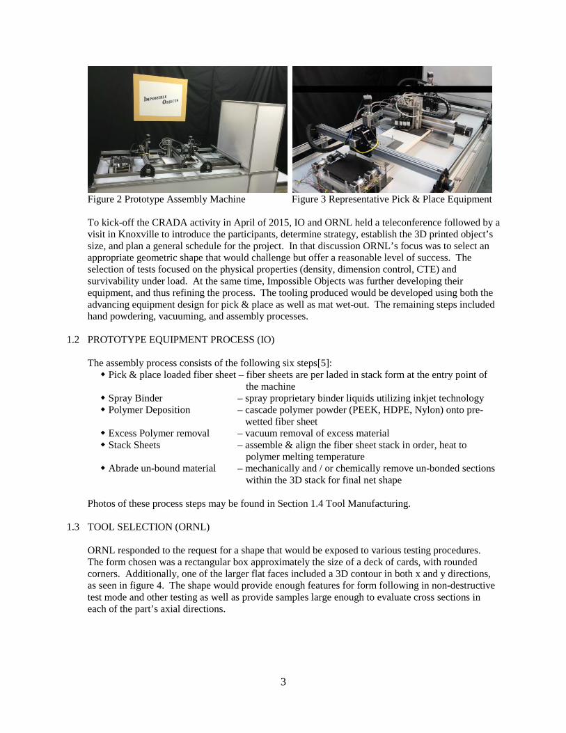
3
Figure 2 Prototype Assembly Machine Figure 3 Representative Pick & Place Equipment To kick-off the CRADA activity in April of 2015, IO and ORNL held a teleconference followed by a visit in Knoxville to introduce the participants, determine strategy, establish the 3D printed object’s size, and plan a general schedule for the project. In that discussion ORNL’s focus was to select an appropriate geometric shape that would challenge but offer a reasonable level of success. The selection of tests focused on the physical properties (density, dimension control, CTE) and survivability under load. At the same time, Impossible Objects was further developing their equipment, and thus refining the process. The tooling produced would be developed using both the advancing equipment design for pick & place as well as mat wet-out. The remaining steps included hand powdering, vacuuming, and assembly processes.
1.2 PROTOTYPE EQUIPMENT PROCESS (IO) The assembly process consists of the following six steps[5]: Pick & place loaded fiber sheet – fiber sheets are per laded in stack form at the entry point of
the machine Spray Binder – spray proprietary binder liquids utilizing inkjet technology Polymer Deposition – cascade polymer powder (PEEK, HDPE, Nylon) onto pre-
wetted fiber sheet Excess Polymer removal – vacuum removal of excess material Stack Sheets – assemble & align the fiber sheet stack in order, heat to
polymer melting temperature Abrade un-bound material – mechanically and / or chemically remove un-bonded sections
within the 3D stack for final net shape
Photos of these process steps may be found in Section 1.4 Tool Manufacturing.
1.3 TOOL SELECTION (ORNL) ORNL responded to the request for a shape that would be exposed to various testing procedures. The form chosen was a rectangular box approximately the size of a deck of cards, with rounded corners. Additionally, one of the larger flat faces included a 3D contour in both x and y directions, as seen in figure 4. The shape would provide enough features for form following in non-destructive test mode and other testing as well as provide samples large enough to evaluate cross sections in each of the part’s axial directions.

4
Figure 4 Initial Sample Tool, as Drawn The design was electronically communicated to IO for the next step of the process, manufacturing the part.
1.4 TOOL MANUFACTURING (IO)
The 3D data was received in SolidWorks CAD format that required the traditional slicing procedure required of all 3D printers. Impossible Object post-processed the data incorporating Autodesk /NETFABB Professional software, transforming the shape into approximately 394 slices, or layers, prior to sending to the prototype’s machine controls. As outlined previously, the process begins with loading the assembly machine with fiber sheets (figure 5), be it carbon, glass, or Kevlar. In this case the chosen material was carbon fiber with a non-woven / random fiber lay. The mats, representing a sliced layer of the part, are transferred to the printing station (figure 6) where proprietary fluids are equivalently ink jetted onto the mat with a resolution of 600dpi, equivalent to an accuracy of ±0.0017”. The mats continue thru a wall shower of dry powdered PEEK material that clings to the wetted portions of the mat. Excess material is vacuumed from the surface, and the powdered mat is ejected from the machine (figure 7) in preparation for precision stacking (figure 8). The final step in the CBAM process is to perform an oven cure, with the material pressed in a compression jig (figure 9). A part’s z-dimension is controlled by the compression jig, the time factor between tightening said jig, oven temperature, and bake time. A finished part is shown in figure 10, with the CRADA Tool trial part in figure 11.

5
Figure 5 Sheet Loading Figure 6 Printing and Sheet Punch
Figure 7 Printed Mat Exiting Vacuum Station Figure 8 Stacking w/ Precision Punched Holes
Figure 9 Compression Jig w/ Baked Part Removed Figure 10 Sample Part In Clean-up
Figure 11 Finished Tool Part for CRADA Work

6
1.5 TOOL EVALUATION (ORNL)
As mentioned in the background review, testing focused on the physical properties of density, dimension control, CTE, and survivability under load. Density was determined thru CT scans, courtesy of Carl Zeiss Industrial Metrology, LLC. No voids were detected. A single inclusion was observed in the scan, thus the indicating the part was fully dense (figure 12).
Figure 12 Screenshot of CT Scan Output, Inclusion Pointed Out in Each Dimension Dimensional control was measured on a gross scale, employing calipers to capture the X, Y, Z Top, and Z Bottom, and diagonal measurements of the sample. It was determined that the dimensional control was within half a percent in both the X and Y dimensions. Noting that Impossible Objects was further developing their equipment, and understanding that the tool was manufactured by means of hand-powdering and vacuuming, the z-height experienced a lesser control, up to 28% delta from design. This divergence was due principally to the volume of polymer, the degree of compression applied, and the amount of polymer ‘blooming’ or phase separation of the material’s components[6]. Results are presented in Table 1.

7
Table 1 Dimensional Analysis Pre-Testing
*Assembly test piece, Z height intentionally truncated
Impossible Objects is targeting the tooling market in both automotive and aerospace applications, thus survivability under autoclave conditions was under investigation. To simulate these conditions, the part was subjected to seven heat cycles, from ambient to 150°C to ambient, and then exposed to 1000 psi as an extreme. Representation photos are found in figures 13 & 14. Table 2 compares the pre- and post- hydroforming dimensions of the material. Minimal dimensional change was experienced, with photographs in figures 15 & 16 showing no physical change to the surface finish, etc. Note that the tool was dissected to obtain samples for further review, shortening the x-dimension.
Table 2 Dimensional Analysis Post-Testing
Figure 13 Hydroformer Post Cycle Figure 14 Part as Pressed
Orientation MeasureTarget
Dimensions
PEEK Tool Pre Hydro-
forming% ∆
Peek Tool Truncated *
% ∆Makerbot
Sample% ∆
Length: Left 3.490 3.471 -0.544% 3.453 -1.060% 3.426 -1.834%Length: Right 3.490 3.471 -0.544% 3.455 -1.017% 3.426 -1.834%
Width: Top 1.960 1.965 0.255% 1.958 -0.102% 1.941 -0.969%Width: Bottom 1.960 1.960 0.000% 1.961 0.051% 1.936 -1.224%
ZB Bottom Thickness 0.540 0.617 14.259% 0.415 N/A 0.542 0.370%ZT Top Thickness 0.300 0.384 27.833% 0.181 N/A 0.328 9.333%
Base Diagonal: TL LR 3.900 3.922 0.564% 3.898 -0.051% 3.864 -0.923%Base Diagonal: TR LL 3.900 3.917 0.436% 3.886 -0.359% 3.899 -0.026%
Small Scale Part
Z
X - Y
Y
X
Orientation MeasurePEEK Tool Pre Hydro-
forming
PEEK Tool Post Hydro-
forming% ∆
Length: Left 3.471Length: Right 3.471
Width: Top 1.965 1.959 -0.305%Width: Bottom 1.960 1.962 0.102%
ZB Bottom Thickness 0.617 0.614 -0.486%ZT Top Thickness 0.384 0.388 1.173%
Small Scale Part, post Hydroforming
Z
Y
XN/AN/A

8
Figure 15 Close-up of Form Over Tool Figure 16 Close-up of Tool after Forming The last property investigated for the PEEK – Carbon Fiber mat composite was the Coefficient of Thermal Expansion (CTE), measured on ORNL’s main campus using the Thermo-Mechanical Analyzer (TMAQ400), and employing ASTM E831 as a guideline[7]. An independent sample set specifically oriented in the x- , y-, and z- directions, was requested from Impossible Objects for CTE analysis. The target size was 3mm x 3mm x ~12mm in length, for a clear estimation of CTE. Published CTE values of unreinforced PEEK ranges from 4.7 ~ 150 µm/m·°C[8] and with carbon fiber fill ranges from 3.00 ~ 110 µm/m·°C [9], as found in Matweb’s technical data. As seen in table 3, our test data fell within these parameters. The plots of the three independent directional samples for Strain vs Temperature are posted in figures 17, 18, & 19, within which the Glass Transition Temperature can clearly be identified.
Figure 17 12 mm Sample: Figure 18 12 mm Sample: Figure 19 12 mm Sample: Strain Curve x-Direction Strain Curve y-Direction Strain Curve z-Direction
Table 3 CTE Analysis
x-Direction y-Direction z-Direction, pre-TG z-Direction, post-TG Sample Length L0 (mm) 11.941 12.024 12.163
CTE (µm/m·°C) 7.81 9.24 92.35 455.36 Glass Transition TG (°C) 142 142 135

9
2.0 Summary of Results The success of the Impossible Objects tool submitted for the first Phase of this CRADA has been greatly encouraging. Understanding that the processes are capable of producing a completely dense part and witnessing the survivability under hydroforming loads gives this process credence to move forward into the realm of actual constructed parts, tools, and compression molds. The agreement with published data, specifically determining where in the range the CTE values fall, establishes that the tools will be compatible with other composite parts and lead to the option that the CBAM tools will survive autoclave exposure. As proposed, Phase II will explore the improvements needed to streamline the assembly machine, improve cycle time, and establish a part size maximum geometry. Additional material characteristics will be determined based on the knowledge gained in Phase I.

10
Appendix A: Anticipating a PHASE II, the following Scope of Work summarizes the intended efforts PHASE II SCOPE of WORK: 1. Equipment Transfer to Knoxville: Full Scale Manufacturing – IO to emplace a large CBAM system
within ORNL’s MDF. Improvements will focus on automation of material handling throughout. 1.1. Automating the Material Deposition
Investigate faster transfer speed for sheet material, eliminate errors 1.2. Automated Stacking
Determine best practices on the 1.3. System Integration
Preferred Slicing direction, location of overlap, etc.
2. Material Property Analysis 2.1. Planning Material
Determine variations between Glass, CF, Kevlar mat, and Powder Polymer. 2.2. Testing of Material Combinations
Prepare coupons specific to CTE, x-, y-, & z- Directional stress / strain analysis, overall dimensional characteristics, autoclave-ability
3. Results 3.1. Communicate results
Determine feasibility 3.2. Commercialization
Impossible Objects to Identify Commercialization Opportunities
11
References: [1] “About - Impossible Objects,” Impossible Objects. [Online]. Available at: http://www.impossible-objects.com/about/#team. [Accessed: 26-Apr-2016]. [2] "Impossible Objects $2.8 M Composites - 3D Printing Industry." 3D Printing Industry Impossible Objects Secures 28 Million for Composites 3D Printing Comments. 2014. Web. 26 Apr. 2016. [3] "Impossible Objects $2.8 M Composites - 3D Printing Industry." 3D Printing Industry Impossible Objects Secures 28 Million for Composites 3D Printing Comments. 2014. Web. 26 Apr. 2016. [4] “CRADA No. NF-15-05698, Appendix A” [5] "Impossible Objects." Impossible Objects. Web. 26 Apr. 2016. [6] "Blooming on Polymers." Tascon -. Web. 26 Apr. 2016. [7] Oak Ridge National Lab ORNL/TM- etc. Coefficient of Thermal Expansion of Materials for Large Scale Polymer Additive Manufacturing – Test Report, G. Velez-Garcia, A. Wright, V. Kunc, C. Duty, March, 2014 [8] “Overview of materials for Polyetheretherketone, Unreinforced,” Overview of materials for Polyetheretherketone, Unreinforced. [Online]. Available at: http://www.matweb.com/search/datasheet.aspx?matguid=2164cacabcde4391a596640d553b2ebe. [Accessed: 26-Apr-2016]. [9] “Overview of materials for Polyetheretherketone, Carbon Fiber Filled,” Overview of materials for Polyetheretherketone, Carbon Fiber Filled. [Online]. Available at: http://www.matweb.com/search/datasheet.aspx?matguid=e0993de8cfa74798876b7883382af4dd. [Accessed: 26-Apr-2016].


![Experimental Investigations of Performance and Emission ... · made in this project to know the feasibility of using blend of biodiesel [Palm Stearin], oxygenated additive [Diethyl](https://static.fdocuments.in/doc/165x107/5e0abd6c4965926cee51322c/experimental-investigations-of-performance-and-emission-made-in-this-project.jpg)