Fea$%e# - Digitrax, Inc. · 4.0 pm42 wiring & d 1 & 2) 1>>bc4ab) c74 02a>bb 28a 3>f= f8;; b7>ac =>c...
16
PM42 Power Manager For 4 Independent Power Sub-Districts Features n Cost effective power management for 4 power sub-districts. n Short circuit management or auto-reversing for each sub-district. n Short circuit management increases layout reliability by preempting booster shutdown when a short circuit is detected by the PM42. This minimizes dis- ruptions to operations by automatically restarting layout operation when the short circuit is cleared. n User selectable short circuit detection sensitivity lets you adjust the PM42 to optimize operation with other equipment on your layout. n Auto-reversing manages polarity mismatches on reversing track sections. n Trains move through reversing sections on your layout automatically, without manually throwing electrical toggle switches or adding another booster. n Connect your PM42 to LocoNet & transmit information to your LocoNet system. n No locomotive wiring modifications needed. n An external power supply is needed to run the PM42 (12-18V AC or DC 125mA minimum output). Digitrax PS14 power supply is sold separately Complete Train Control Run Your Trains, Not Your Track! All Scales Short Circuit Management or Auto Reversing ©2010 Digitrax, Inc. www.digitrax.com
-
Upload
nguyenthuy -
Category
Documents
-
view
215 -
download
0
Transcript of Fea$%e# - Digitrax, Inc. · 4.0 pm42 wiring & d 1 & 2) 1>>bc4ab) c74 02a>bb 28a 3>f= f8;; b7>ac =>c...

PM42Power Manager For 4 Independent
Power Sub-Districts
Featuresn Cost effective power management for 4 power sub-districts.
n Short circuit management or auto-reversing for each sub-district.
n Short circuit management increases layout reliability by preempting boostershutdown when a short circuit is detected by the PM42. This minimizes dis-ruptions to operations by automatically restarting layout operation when theshort circuit is cleared.
n User selectable short circuit detection sensitivity lets you adjust the PM42 tooptimize operation with other equipment on your layout.
n Auto-reversing manages polarity mismatches on reversing track sections.
n Trains move through reversing sections on your layout automatically, withoutmanually throwing electrical toggle switches or adding another booster.
n Connect your PM42 to LocoNet & transmit information to your LocoNetsystem.
n No locomotive wiring modifications needed.
n An external power supply is needed to run the PM42 (12-18V AC or DC125mA minimum output). Digitrax PS14 power supply is sold separately
Complete Train ControlRun Your Trains, Not Your Track!
All Scales
Short Circuit Management or Auto Reversing
©2010 Digitrax, Inc. www.digitrax.com

1
1.0 Introduction 2
2.0 Terminology 2
3.0 PM42 Operation 2
3.1 Short Circuit Management 2
3.2 Auto-Reversing 3
4.0 PM42 Wiring 4
5.0 PM42 Option Switch (OpSw) Set Up 9
5.1 PM42 Trip Current 10
5.2 Setting the Short Circuit Sensitivity of the PM42 11
5.3 Setting the PM42 for Auto-Reversing Operation 12
6.0 Using your PM42 on LocoNet 12
6.1 Setting the PM42’s board address: 12
7.0 Troubleshooting 13
8.0 Warranty and Repair Information 14
9.0 FCC Information 14
PM42 Power Manager
Instruction Manual
Table of Contents
Digitrax, LocoNet, Super Empire Builder, Super Chief, Zephyr, Radio
Equipped, AutoReversing, FX, UniVersal Consisting, Jump, and others are
trademarks of Digitrax, Inc.
Digitrax, Inc. is not responsible for unintentional errors
or omissions in this document.
This manual is copyright Digitrax, Inc. 2004-2010
Printed in USA All Rights Reserved REV 12/2009
Digitrax Manuals & Instructions are updated periodically.
Please visit www.digitrax.com for the latest version of all manuals.

1.0 Introduction
The PM42 can control 4 independent power sub-districts that can each be set
up as either a "Short Circuit Manager" (default) or an "Auto-Reversing
Controller." Each of the 4 sub-districts can be set for slow, regular, faster or
fastest short circuit management depending on the needs of the user. A separate
booster can power each of these sub-districts or multiple boosters can power
any combination. Each PM42 requires a 12 to 18V AC or DC 125mA power
supply (sold separately such as Digitrax PS14). One power supply (125mA per
PM42) can power more than one PM42 as long as it provides 125mA per
PM42 and is not used to power any other device. DO NOT share a power sup-
ply between your PM42 and any command station or booster on the layout.
Digitrax does not recommend sharing a power supply between one or
more PM42s and any other device on the layout.
Analog operation or zero stretching will adversely affect booster or PM42
detection times for auto-reversing and short circuit detection.
2.0 Terminology
Power District or District: The power wiring, components and equip-
ment attached to that wiring that are driven from a single properly
isolated booster. In the case of the PM42 a district is a part of the
layout that is double gapped at both ends and powered by a single
booster.
Sub-district: A subdivision of a district. With one PM42, you can create
4 sub-districts. These 4 sub-districts can all be within one district
powered by one booster or they can be spread over more than one
district.
Section: One fourth of a PM42. Each PM42 is divided into 4 sections.
We call these Section 1, Section 2, Section 3, and Section 4. Each
section of a PM42 can be set up either for short circuit management
or auto-reversing.
3.0 PM42 Operation
3.1 Short Circuit Management
When the PM42 detects a short circuit, it will shut down the sub-district where
the short occurs. The "SUB-DISTRICT STATUS" LED for the sub-district with
the short circuit will light red. The other sub-districts will continue to operate.
PM42 reconnection or automatic restart attempts may cause brief power inter-
ruptions to the booster output if the short circuit is not cleared.
2

The PM42 offers four settings for short circuit detection sensitivity. These four
settings let you optimize your PM42 for operation with other equipment you
use on your layout.
When a short circuit occurs on any layout, the voltage at the booster will col-
lapse. The purpose of the PM42 is to preempt the booster shutdown to mini-
mize disruptions to layout operations by automatically re-starting the layout
when this happens. In most cases, you will not notice any power interruption in
the operation of DCC equipped locomotives. This is because most DCC
decoders store energy to keep their CPUs alive in case of brief power interrup-
tions and the inertia of a moving locos will usually keep it moving as long as
the short does not last too long. Because power storage characteristics vary
from decoder to decoder, some are more sensitive to short circuits than others.
To compensate for more sensitive decoders, the PM42 can be set for faster or
fastest short circuit detection. Slower short circuit detection may be a better
choice if you are running locos with lots of incandescent lamps or lighted pas-
senger cars because when you turn these on, there is a brief current spike that
may be indistinguishable from a short circuit to the system.
3.2 Auto-Reversing
When a train enters a PM42 reverse section sub-district that is set up for "Auto-
Reversing" and there is a polarity mis-match, the PM42 will automatically
change the polarity of that sub-district and the train will continue to run
through the reversing track section. The "SUB-DISTRICT STATUS" LED for
that sub-district will light red or go off, depending on the polarity needed to
correct the auto-reversing polarity mis-match.
When auto-reversing occurs on the layout the direction of travel of non decoder
equipped or "conventional" locos WILL be affected depending on where they
are on the layout and on which part of the track has its polarity reversed to
allow for auto-reversing. We recommend that analog locos not be run on
any layout that is using auto-reversing because they may suddenly change
direction when track polarity is changed by the auto-reversing feature.
Since the PM42 operates "downstream" of the Digitrax boosters it is con-
strained by the operating characteristics of the boosters; i.e. the current avail-
able during a short circuit and the timing setup of the boosters. A correctly
wired and configured PM42 will operate before booster fault shutdown and dis-
connect any load detected as a "short circuit". The PM42 will automatically
attempt to reconnect any short circuit detected until the short circuit is cleared.
3

4.0 PM42 Wiring
(See TABLES I &II and Diagrams 1 & 2)
1. Before installing the PM42 on your layout, be sure that your boosters
shut down correctly when a short circuit occurs. To do this, short the
track in each power district. Use a coin or screwdriver blade across
the tracks in several locations within the district to create a short cir-
cuit. The booster in the shorted district should beep and shut down
each time you short the track, the other boosters and districts will
continue to run. Once the short is cleared, the booster that was short-
ed should automatically resume operation. If the booster does not
shut down as described, then more or heavier feeder wires or bus
wires may be necessary to correct this.
2. Connect the wires from the booster's Rail A & Rail B outputs to the
Rail A & Rail B inputs for one section of the PM42 that will be
powered by that booster. (See TABLES I & II for connection
details for each PM42 section). You can use a different booster to
drive each of the PM42's four sections if desired.
3. Wire at least one of the PM42's ground connections (Pin B or X) to
the Digitrax booster ground, common (or case) of the boosters.
4. Wire the PM42's Track Outputs A&B to the A&B rails of the track to
be controlled.
5. To make a PM42 section "AutoReversing" first, connect the "REV"
pins and adjacent "TRACK OUTPUT" pins on the 44 -pin connector
for that PM42 section as shown in Diagrams 1 & 2. Then, set the
related op switch (OpSw) for Auto-reversing. (See TABLE III for
OpSw number). See Section 5.0 PM42 OpSw Set Up.
6. Connect a 12-18V AC or DC power supply to the AC1 (Pin 3) and
AC2 (Pin C) terminals of the 44-pin connector. This powers the
PM42(s). Multiple PM42s can be supplied by a single power supply
as long as you provide 125mA for each PM42. This supply should
not power or be shared by any devices other than PM42s.
Tracks should be double gapped between adjacent power districts.
Be sure the 44-pin connector is plugged in to the PM42 with the numbered pin
labels on the component side of the board. (See PM42 Top View on Front
Cover of this manual).
4

* Note if Auto-reversing is not set up for any given PM42 section, do not
connect REV A or REV B Pins
5

**Ground (Pin B or X) must be made to booster for correct PM42 operation.
6

7
A
A
D
D
H
H
J
J
M
M
N
N
S
S
T
T
W
W
Y
Y
Z
Z
BOTTOM ROW
BOTTOM ROW
1
1
2
2
5
5
6
6
9
9
10
10
13
13
14
14
17
17
18
18
20
20
21
21
22
22
TOP ROW
TOP ROW
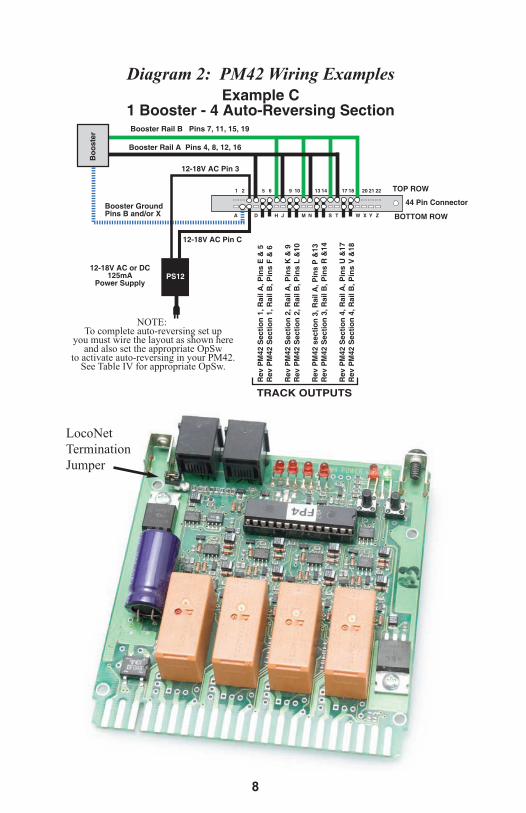
Diagram 1: PM42 Wiring Examples Diagram 2: PM42 Wiring Examples
44 Pin Connector
44 Pin Connector
Booster 1, Rail B Pins 15, 19
Booster 1, Rail A Pins 12, 16
PM42
Sec
tion
1, R
ail A
, Pin
EPM
42 S
ectio
n 1,
Rai
l A, P
in E
Example A1 Booster - 4 Short Circuit Managers
Example B2 Boosters - 4 Short Circuit Managers
PM42
Sec
tion
1, R
ail B
, Pin
FPM
42 S
ectio
n 1,
Rai
l B, P
in F
PM42
Sec
tion
2, R
ail A
, Pin
KPM
42 S
ectio
n 2,
Rai
l A, P
in K
PM42
Sec
tion
2, R
ail B
, Pin
LPM
42 S
ectio
n 2,
Rai
l B, P
in L
PM42
Sec
tion
3, R
ail A
, Pin
PPM
42 S
ectio
n 3,
Rai
l A, P
in P
PM42
Sec
tion
3, R
ail B
, Pin
RPM
42 S
ectio
n 3,
Rai
l B, P
in R
PM42
Sec
tion
4, R
ail A
, Pin
UPM
42 S
ectio
n 4,
Rai
l A, P
in U
PM42
Sec
tion
4, R
ail B
, Pin
VPM
42 S
ectio
n 4,
Rai
l B, P
in V
Booster 2, Rail B Pins 7, 11
Booster 2, Rail A Pins 4, 8
Factory Settings (DEFAULT)
A D H J M N S T W Y Z BOTTOM ROW
1 2 5 6 9 10 13 14 17 18 20 21 22 TOP ROW
44 Pin Connector
Rev
PM
42 S
ectio
n 1,
Rai
l A, P
ins
E &
5
Rev
PM
42 S
ectio
n 2,
Rai
l A, P
ins
K &
9
Rev
PM
42 s
ectio
n 3,
Rai
l A, P
ins
P &
13
Rev
PM
42 S
ectio
n 4,
Rai
l A, P
ins
U &
17
Rev
PM
42 S
ectio
n 1,
Rai
l B, P
ins
F &
6
Rev
PM
42 S
ectio
n 2,
Rai
l B, P
ins
L &
10
Rev
PM
42 S
ectio
n 3,
Rai
l B, P
ins
R &
14
Rev
PM
42 S
ectio
n 4,
Rai
l B, P
ins
V &
18
Example C1 Booster - 4 Auto-Reversing SectionBooster Rail B Pins 7, 11, 15, 19
Booster Rail A Pins 4, 8, 12, 16
Boo
ster
1B
oost
er 2
12-18V AC Pin 3
12-18V AC Pin C
Booster Ground
Pins B and/or X
Bo
os
ter
12-18V AC Pin 3
12-18V AC Pin C
Booster Ground
Pins B and/or X
12-18V AC or DC125mA
Power Supply
12-18V AC or DC125mA
Power Supply
Bo
ost
er
Booster Rail B Pins 7, 11, 15 ,19
Booster Rail A Pins 4, 8, 12, 16
Booster 2 Booster 1
12-18V AC Pin 3
12-18V AC Pin C
Booster GroundPins B and/or X
12-18V AC or DC125mA
Power Supply
PS12
PS12
PS12
X
X
X
TRACK OUTPUTS
TRACK OUTPUTSTRACK OUTPUTS
NOTE: To complete auto-reversing set up
you must wire the layout as shown hereand also set the appropriate OpSw
to activate auto-reversing in your PM42.See Table IV for appropriate OpSw.
A D H J M N S T W Y Z BOTTOM ROW
1 2 5 6 9 10 13 14 17 18 20 21 22 TOP ROW
44 Pin Connector
Booster 1, Rail B Pins 15, 19
Booster 1, Rail A Pins 12, 16
PM42
Sec
tion
1, R
ail A
, Pin
E &
5
Example DBooster #1 - 2 Short Circuit Managers
Booster #2 - 2 Auto Reverse Controllers
PM42
Sec
tion
1, R
ail B
, Pin
F &
6
PM42
Sec
tion
2, R
ail A
, Pin
K &
9PM
42 S
ectio
n 2,
Rai
l B, P
in L
& 1
0
PM42
Sec
tion
3, R
ail A
, Pin
PPM
42 S
ectio
n 3,
Rai
l B, P
in R
PM42
Sec
tion
4, R
ail A
, Pin
UPM
42 S
ectio
n 4,
Rai
l B, P
in V
Booster 2, Rail B Pins 7, 11
Booster 2, Rail A Pins 4, 8
Boo
ster
1B
oost
er 2
Auto-ReverseControllers
Short Circuit Managers
12-18 VAC Pin 3
12-18 VAC Pin C
Booster GroundPins B and/or X
12-18 VAC or DC125mA
Power SupplyPS12
X
NOTE: To complete auto-reversing set up
you must wire the layout as shown hereand also set the appropriate OpSw
to activate auto-reversing in your PM42.See Table IV for appropriate OpSw.
TRACK OUTPUTS
8
A
A
D
D
H
H
J
J
M
M
N
N
S
S
T
T
W
W
Y
Y
Z
Z
BOTTOM ROW
BOTTOM ROW
1
1
2
2
5
5
6
6
9
9
10
10
13
13
14
14
17
17
18
18
20
20
21
21
22
22
TOP ROW
TOP ROW
Diagram 1: PM42 Wiring Examples Diagram 2: PM42 Wiring Examples
44 Pin Connector
44 Pin Connector
Booster 1, Rail B Pins 15, 19
Booster 1, Rail A Pins 12, 16
PM42
Sec
tion
1, R
ail A
, Pin
EPM
42 S
ectio
n 1,
Rai
l A, P
in E
Example A1 Booster - 4 Short Circuit Managers
Example B2 Boosters - 4 Short Circuit Managers
PM42
Sec
tion
1, R
ail B
, Pin
FPM
42 S
ectio
n 1,
Rai
l B, P
in F
PM42
Sec
tion
2, R
ail A
, Pin
KPM
42 S
ectio
n 2,
Rai
l A, P
in K
PM42
Sec
tion
2, R
ail B
, Pin
LPM
42 S
ectio
n 2,
Rai
l B, P
in L
PM42
Sec
tion
3, R
ail A
, Pin
PPM
42 S
ectio
n 3,
Rai
l A, P
in P
PM42
Sec
tion
3, R
ail B
, Pin
RPM
42 S
ectio
n 3,
Rai
l B, P
in R
PM42
Sec
tion
4, R
ail A
, Pin
UPM
42 S
ectio
n 4,
Rai
l A, P
in U
PM42
Sec
tion
4, R
ail B
, Pin
VPM
42 S
ectio
n 4,
Rai
l B, P
in V
Booster 2, Rail B Pins 7, 11
Booster 2, Rail A Pins 4, 8
Factory Settings (DEFAULT)
A D H J M N S T W Y Z BOTTOM ROW
1 2 5 6 9 10 13 14 17 18 20 21 22 TOP ROW
44 Pin Connector
Rev
PM
42 S
ectio
n 1,
Rai
l A, P
ins
E &
5
Rev
PM
42 S
ectio
n 2,
Rai
l A, P
ins
K &
9
Rev
PM
42 s
ectio
n 3,
Rai
l A, P
ins
P &
13
Rev
PM
42 S
ectio
n 4,
Rai
l A, P
ins
U &
17
Rev
PM
42 S
ectio
n 1,
Rai
l B, P
ins
F &
6
Rev
PM
42 S
ectio
n 2,
Rai
l B, P
ins
L &
10
Rev
PM
42 S
ectio
n 3,
Rai
l B, P
ins
R &
14
Rev
PM
42 S
ectio
n 4,
Rai
l B, P
ins
V &
18
Example C1 Booster - 4 Auto-Reversing SectionBooster Rail B Pins 7, 11, 15, 19
Booster Rail A Pins 4, 8, 12, 16
Boo
ster
1B
oost
er 2
12-18V AC Pin 3
12-18V AC Pin C
Booster Ground
Pins B and/or X
Bo
os
ter
12-18V AC Pin 3
12-18V AC Pin C
Booster Ground
Pins B and/or X
12-18V AC or DC125mA
Power Supply
12-18V AC or DC125mA
Power Supply
Bo
ost
er
Booster Rail B Pins 7, 11, 15 ,19
Booster Rail A Pins 4, 8, 12, 16
Booster 2 Booster 1
12-18V AC Pin 3
12-18V AC Pin C
Booster GroundPins B and/or X
12-18V AC or DC125mA
Power Supply
PS12
PS12
PS12
X
X
X
TRACK OUTPUTS
TRACK OUTPUTSTRACK OUTPUTS
NOTE: To complete auto-reversing set up
you must wire the layout as shown hereand also set the appropriate OpSw
to activate auto-reversing in your PM42.See Table IV for appropriate OpSw.
A D H J M N S T W Y Z BOTTOM ROW
1 2 5 6 9 10 13 14 17 18 20 21 22 TOP ROW
44 Pin Connector
Booster 1, Rail B Pins 15, 19
Booster 1, Rail A Pins 12, 16
PM42
Sec
tion
1, R
ail A
, Pin
E &
5
Example DBooster #1 - 2 Short Circuit Managers
Booster #2 - 2 Auto Reverse Controllers
PM42
Sec
tion
1, R
ail B
, Pin
F &
6
PM42
Sec
tion
2, R
ail A
, Pin
K &
9PM
42 S
ectio
n 2,
Rai
l B, P
in L
& 1
0
PM42
Sec
tion
3, R
ail A
, Pin
PPM
42 S
ectio
n 3,
Rai
l B, P
in R
PM42
Sec
tion
4, R
ail A
, Pin
UPM
42 S
ectio
n 4,
Rai
l B, P
in V
Booster 2, Rail B Pins 7, 11
Booster 2, Rail A Pins 4, 8
Boo
ster
1B
oost
er 2
Auto-ReverseControllers
Short Circuit Managers
12-18 VAC Pin 3
12-18 VAC Pin C
Booster GroundPins B and/or X
12-18 VAC or DC125mA
Power SupplyPS12
X
NOTE: To complete auto-reversing set up
you must wire the layout as shown hereand also set the appropriate OpSw
to activate auto-reversing in your PM42.See Table IV for appropriate OpSw.
TRACK OUTPUTS
LocoNet
Termination
Jumper

5.0 PM42 Option Switch (OpSw) Set Up
The PM42 OpSw settings are used to set up the PM42 for setting up the trip
current, short circuit management (including sensitivity), and/or auto-reversing.
Follow the steps outlined below to set up OpSws according to the TABLES
below.
Connect a DT series throttle (with battery installed) to the LocoNet connector
on your powered PM42 to read back and make changes to the PM42's option
switches (OpSws).
The factory default setting on all PM42 OpSws is "thrown" or "t". This setting
will operate each section of the PM42 as a short circuit manager.
To Change PM42 OpSw settings:
1. Enter option switch mode by pressing the "OPTION" button on the
PM42 for about 1 second and then releasing it. The green "ID" LED
and red "OPTION" LED will flash alternately to indicate that you
have entered option switch mode.
2. Connect any Digitrax DT series throttle to the PM42's LocoNet con-
nector. Note that because the throttle’s switch control mode is used
to change the PM42's OpSw settings, each time you change the
PM42's option switch settings you will also send switch commands
to the layout any time you are connected to LocoNet and the layout.
3. If the PM42 is connected to a working LocoNet (via a 6 conductor
LocoNet cable), skip to step 4 since the LocoNet termination jumper
is not needed. If the PM42 is not connected to a working LocoNet,
move the LocoNet termination jumper so that it is across both pins.
The LocoNet termination jumper is, located behind the RJ12 sockets
on the PM42 board.
4. Follow the instructions for the throttle you are using to enter switch
control mode on the throttle. Select the switch address that corre-
sponds to the OpSw number you want to change. Press the "c" or "t"
button to change the OpSw setting as desired.
5. When OpSw set up is complete, press the PM42’s "OPTION" button
and the unit will exit option switch mode. If you moved the LocoNet
termination jumper in step 3 above, return it to its original position
(leave it attached to one pin so that you don't lose the jumper).
9

5.1 PM42 Trip Current
The PM42 factory default for trip current is set at 3 amps. This is the current
that all Digitrax boosters can provide briefly under fault conditions with ade-
quate track wiring. A 3 amp trip current will work for most boosters and lay-
outs. If you have many locomotives running or other large power draws in a
sub-district or you need to use currents higher than 3 amps, you can modify the
current threshold for all four sections of the PM42 to any value between 1.5
amps and 12 amps, in increments of approximately 1.5 amps. Simply change
option switches 01, 02 and 09 according to TABLE III to adjust PM42’s trip
current for optimal operation on your layout.
10

5.2 Setting the Short Circuit Sensitivity of the PM42
Slow short circuit detection is best for layouts using heavy lamp loads and/or
slower boosters.
Standard short circuit detection works for most HO locos on most Digitrax lay-
outs.
Faster short circuit detection can be used with most HO & N scale locos on
most Digitrax layouts. Faster short circuit detection should be used with auto-
reversing sections of your PM42.
Fastest short circuit detection for use with decoders that are particularly sensi-
tive to power interruptions, and should be the setting for autoreversing.
11

5.3 Setting the PM42 for Auto-Reversing Operation
Once you have wired one or more sections of the PM42 for auto-reversing
according to the instructions in Section 4.0 of this manual, use TABLE V
below to determine which OpSw you must set to enable auto-reversing in the
PM42 section/s you want to use as auto-reversing.
We recommend that you set your short circuit detection sensitivity to the
“Fastest” setting when using auto-reversing.
6.0 Using your PM42 on LocoNet
The PM42 will operate with no connection to LocoNet. To put your PM42 on
LocoNet, use the two LocoNet connectors on the PM42 to connect it to
LocoNet using 6 conductor cables just like any other LocoNet device on your
layout.
If connected to LocoNet, the PM42 sends information to the system as faults
are detected, cleared, and when auto-reversing occurs. If you wish to report
PM42 status information to LocoNet and attached devices or computers that
can interpret these messages, you must set up a unique board address for each
PM42.
6.1 Setting the PM42’s board address:
1. Connect a Digitrax DT series throttle to the LocoNet port on your
PM42.
2. If the PM42 is not connected to a working LocoNet (via a 6 conduc-
12

tor LocoNet cable), position the LocoNet termination jumper, locat-
ed behind the RJ12 sockets, across both pins. If the PM42 is con-
nected to a working LocoNet, you do not need to use the LocoNet
termination jumper.
3. Press and hold the "ID" button behind the green LED for about 1 sec-
ond. The green "ID" LED will blink when the button is released.
This indicates that the PM42 is in board address setting mode.
4. Enter switch control mode on the throttle according to the throttle’s
instructions. Select the switch address that corresponds to the board
address you want to assign to the PM42. Press the "c" button to
issue a "closed" command. This will set the board address the same
number as the switch address you selected. The green "ID" LED will
change to steady green indicating PM42 Power ON and that board
address setting mode is complete. Be sure to reconnect to LocoNet
and return the LocoNet termination jumper to its original position.
5. To exit board address setting mode with no changes, press the "ID"
button a second time and hold it for about 1 second. Be sure to
reconnect to LocoNet and if you use the LocoNet termination
jumper, move it back to its original position.
7.0 Troubleshooting
Short circuit is indicated when lights are turned on in locos or rolling
stock.
Because turning on incandescent lamps creates a brief current spike that
may be detected as a short circuit by the system, you need to
decrease your short circuit detection sensitivity. See Table IV for
appropriate settings for each PM42 section.
DCC locos do not resume operation immediately after short circuit shut-
down.
1. Because of the differences in the amount of energy stored by different
decoders, you may need to increase the sensitivity of your short cir-
cuit detection. See Table IV for appropriate settings for each PM42
section.
2. Set the decoder’s CVs for Accel and Decel to 0. This will allow the
decoders to start the loco moving immediately when power is
restored to the track. Use your Digitrax throttle to simulate accelera-
tion and deceleration instead.
13

8.0 Warranty and Repair InformationDigitrax gives a one year “No Worries" Warranty against manufacturing
defects and accidental customer damage on all Digitrax products.
That's it! A simple, straightforward warranty with no tricky language!
Visit www.digitrax.com for complete warranty details and instructions for
returning items for repair.
For complete warranty details see www.digitrax.com.
9.0 FCC Information Radio or TV Interference: (this information is MANDATED by the FCC) This equip-
ment has been tested and found to comply with the limits for a Class B digital device,
pursuant to part 15 of the FCC rules. These limits are designed to provide reasonable
protection against harmful interference when the equipment is operated in a residential
environment. This equipment generates, uses and can radiate radio frequency energy
and, if not installed and used in accordance with the instruction manual, may cause
harmful interference to radio communications. However, there is no guarantee that inter-
ference will not occur in a particular installation. If this equipment does cause harmful
interference to radio or television reception, which can be determined by turning the
equipment off and on, the user is encouraged to try to correct the interference by one or
more of the following measures:
-Reorient or relocate the receiving antenna.
-Increase the separation between the equipment and the receiver.
-Connect the equipment into an outlet on a circuit different form that
to which the receiver is connected.
-Consult the dealer or an experienced radio/TV technician for help.
Note that any modifications to the equipment not expressly approved by Digitrax voids
the user's authority to operate under and be in compliance with CFR 47 rules, as
administered by the Federal Communication Commission. Digitrax believes any con-
scientiously installed equipment following guidelines in this manual would be
unlikely to experience RFI problems.
14

Made in U.S.A.
306-1001-0001
PM42Power Manager
2443 Transmitter RoadPanama City, FL 32404
www.digitrax.comT 850-872-9890F 850-872-9557
Available
Computer InterfaceComputer InterfaceDecoder ProgrammerDecoder ProgrammerSound ProgrammerSound Programmer
TM
EEMPIREMPIRE B BUILDERUILDERSuperSuper
00 00 00 00