FEA Modelling of Expandable Sand Screens
12
2008 Abaqus Users’ Conference 1 FEA Modelling of Expandable Sand Screens C. Jones and K. Watson Weatherford International Ltd. Abstract: Expandable sand screens are a relatively novel sand control system, which are used to control the ingress of solids in oil and gas reservoirs with weak and unconsolidated formations. They combine the ease of installation of conventional screens with the borehole support of a gravel pack. There are two different variations of expandable screens; a system based on a slotted basepipe which are easy to expand but relatively low in strength and a system based on a drilled basepipe which are very strong but difficult to expand. FEA has been used to model the slotted basepipe type to better understand the interaction of the expanded screen with the rock formations. This type of analysis has replaced earlier, simple analytical, models based on tunneling theory. There are many advantages to using FEA. It allows a better choice of material models for the rock such as Drucker Prager and Cap models. It also allows the investigation of a wider range of configurations, such as the effect of an annulus or the interfaces between different formations. The results from the FEA modeling compares favorably with data from earlier, large scale, experiments. This satisfactory outcome increases confidence in the modeling and has allowed us to design models for field applications. Keywords: Constitutive Model, Critical State Plasticity, Design Optimization, Experimental Verification, Geomechanics, Wellbore. 1. Introduction Expandable sand screens (ESS ® ) are a relatively new sand control system (Metcalfe, 1999). They are used to control the ingress of sand in oil, gas and water wells in reservoirs with weak and unconsolidated formations. The sand is produced due to rock failure as a consequence of the changes in in-situ stress over the life cycle of the well. There are many different strategies available to control produced sand downhole. They range from the very simple, such as reducing production rate, to more complex mechanical restraint of ® ESS is a registered trademark of Weatherford International Ltd.
Transcript of FEA Modelling of Expandable Sand Screens
2008 Abaqus Users’ Conference 1
FEA Modelling of Expandable Sand Screens
C. Jones and K. Watson
Weatherford International Ltd.
Abstract: Expandable sand screens are a relatively novel sand control system, which are used to
control the ingress of solids in oil and gas reservoirs with weak and unconsolidated formations.
They combine the ease of installation of conventional screens with the borehole support of a
gravel pack.
There are two different variations of expandable screens; a system based on a slotted basepipe
which are easy to expand but relatively low in strength and a system based on a drilled basepipe
which are very strong but difficult to expand.
FEA has been used to model the slotted basepipe type to better understand the interaction of the
expanded screen with the rock formations. This type of analysis has replaced earlier, simple
analytical, models based on tunneling theory. There are many advantages to using FEA. It
allows a better choice of material models for the rock such as Drucker Prager and Cap models. It
also allows the investigation of a wider range of configurations, such as the effect of an annulus
or the interfaces between different formations.
The results from the FEA modeling compares favorably with data from earlier, large scale,
experiments. This satisfactory outcome increases confidence in the modeling and has allowed us
to design models for field applications.
Keywords: Constitutive Model, Critical State Plasticity, Design Optimization, Experimental
Verification, Geomechanics, Wellbore.
1. Introduction
Expandable sand screens (ESS®) are a relatively new sand control system (Metcalfe, 1999). They
are used to control the ingress of sand in oil, gas and water wells in reservoirs with weak and
unconsolidated formations. The sand is produced due to rock failure as a consequence of the
changes in in-situ stress over the life cycle of the well.
There are many different strategies available to control produced sand downhole. They range
from the very simple, such as reducing production rate, to more complex mechanical restraint of
® ESS is a registered trademark of Weatherford International Ltd.
2 2008 ABAQUS Users’ Conference
the sand. Two mechanical sand control methods are sand screens and gravel packs. A sand screen
is a metal filter which filters the sand out of the produced fluids in the reservoir. A gravel pack is
a common addition to a sand screen where a sand pack fills the annulus between a sand screen and
the formation; this supports the wellbore and retains the formation sand. There are many
advantages to the gravel pack in terms of solids retention and system reliability. However, the
gravel is pumped into place as slurry. This is a complicated and expensive process which can also
give rise to severe production impairment.
Expandable sand screens are a system which combines the ease of installation of the normal sand
screen with the wellbore support and sand retention of a gravel pack. In an expandable sand
screen installation the screen is run in-hole to depth in an unexpanded form. An expansion tool is
then passed through the screen to swage it onto the wall of the wellbore.
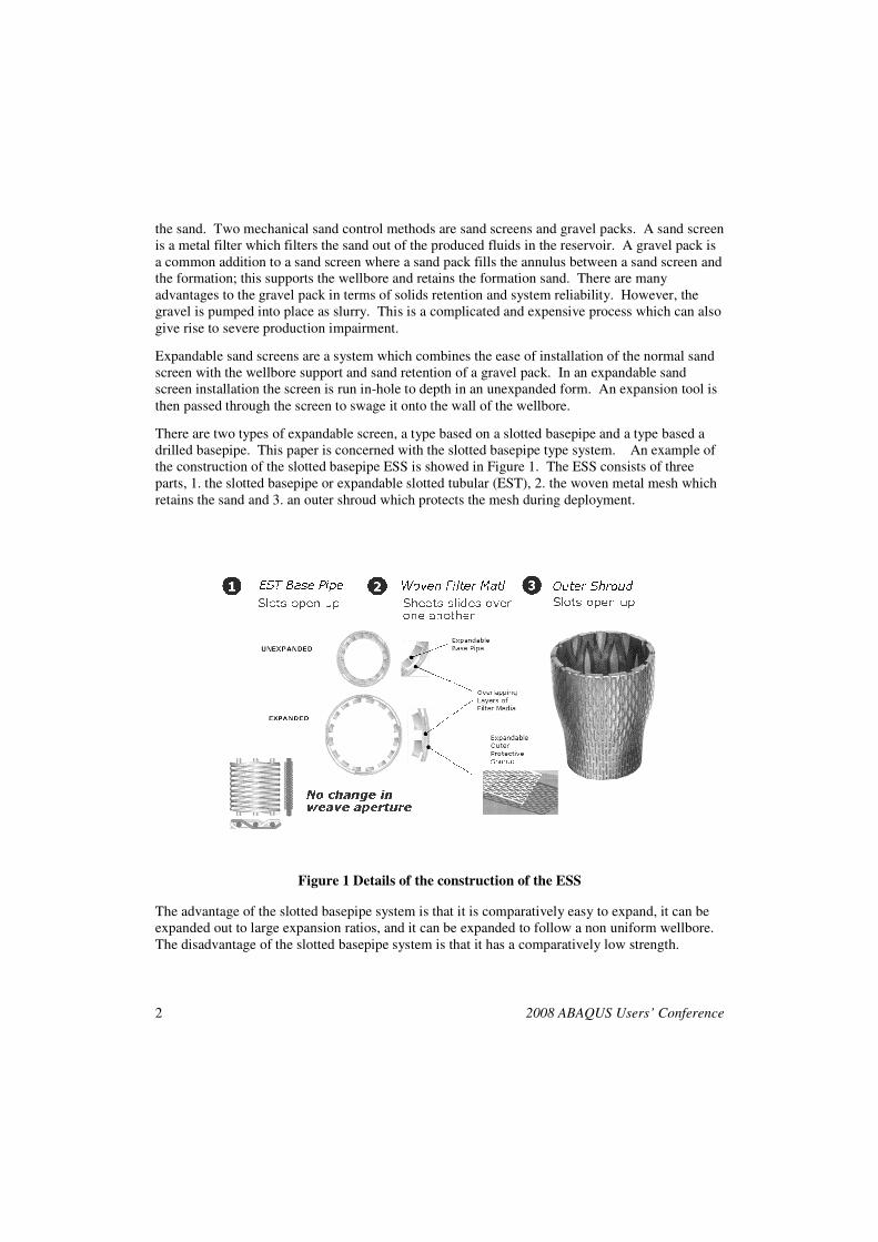
There are two types of expandable screen, a type based on a slotted basepipe and a type based a
drilled basepipe. This paper is concerned with the slotted basepipe type system. An example of
the construction of the slotted basepipe ESS is showed in Figure 1. The ESS consists of three
parts, 1. the slotted basepipe or expandable slotted tubular (EST), 2. the woven metal mesh which
retains the sand and 3. an outer shroud which protects the mesh during deployment.
Figure 1 Details of the construction of the ESS
The advantage of the slotted basepipe system is that it is comparatively easy to expand, it can be
expanded out to large expansion ratios, and it can be expanded to follow a non uniform wellbore.
The disadvantage of the slotted basepipe system is that it has a comparatively low strength.
2008 Abaqus Users’ Conference 3
Although the ESS has a comparatively low strength, numerous experiments have shown that this
is not an issue since the interaction of the screen with the rock formation allows the system to
withstand huge changes in stress with only minimal deformation. However in a very weak rock
the screen will potentially undergo large deformations. A simple analytical model has been
developed to act as an application screening tool (Jones, 2005). The model is based on tunnel
support concepts and uses a Mohr Coulomb representation of the formation materials. The model
has been used extensively to decide which applications are feasible based on the rock strength and
the in-situ stresses.
The simple analytical model has been very successful, but it is also limited. It is limited in the
types of material it can deal with and it is essentially a one dimensional model. To overcome
these limitations an FEA model was developed using Abaqus/CAE. This allowed the study of
more realistic rock material models and structural interactions to be investigated, such as the
effects of an open annulus between the ESS and the rock formations and the interaction with
multiple formations. FEA investigations have been done in the past on the ESS by the oil
companies who use the product (Willson 2002). We have also contracted out numerous FEA
studies on the ESS, but this is the first time we have developed an in-house FEA capability.
2. Work flow and model
The basic work flow was firstly to develop a model representing testing which had already been
done on the ESS. This allowed verification of the model with the test data. Secondly the model
was used to predict the deformation of the ESS in an ESS/rock deformation experiment. In each
case Abaqus/Explicit was used because of its advantages in dealing with multiple, changing
contact surfaces and the large scale plasticity in the systems modeled.
The initial simulations were performed on the 4 1/2” version of the ESS. The model verification
was an extensive set of tests performed to measure the hydraulic collapse resistance.
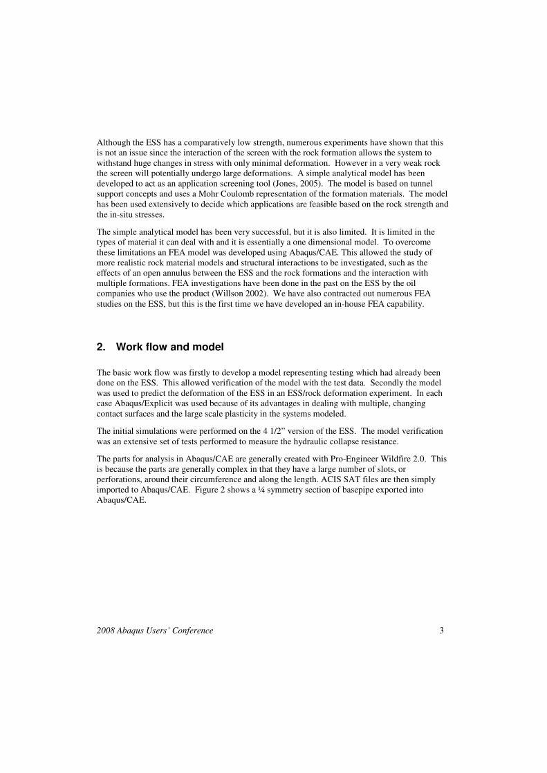
The parts for analysis in Abaqus/CAE are generally created with Pro-Engineer Wildfire 2.0. This
is because the parts are generally complex in that they have a large number of slots, or
perforations, around their circumference and along the length. ACIS SAT files are then simply
imported to Abaqus/CAE. Figure 2 shows a ¼ symmetry section of basepipe exported into
Abaqus/CAE.
4 2008 ABAQUS Users’ Conference
Figure 2 Section of basepipe withC3D8R mesh
Once successfully imported into Abaqus/CAE the part is then meshed. Generally C3D8R
elements are used. For the EST shown (quarter symmetry) mesh four deep (from outside to inner
bore) are used. The perforated shroud is generally meshed with a single layer of tet elements.
Hex elements have been tried but they become too small and too numerous for realistic
computation times. In these simulations the metal filtration weave is ignored. The reason for this
is its complex structure and its small contribution to strength. However the deformation of the
weave during expansion and production is a crucial aspect and will be investigated in the future.
For the full symmetry simulations, one end was held by constraining U1 = 0. The co-efficient of
friction for all interactions was set to 0.5. The basepipe and the outer shroud were made from
stainless steel 316L, with a yield of 206MPa, with a Young’s modulus of 210GPa and a Poisson’s
ratio of 0.3.
Typical run times for the quarter symmetry models were 2-3hrs and 6-8hrs for the full symmetry
versions.
3. Model Results
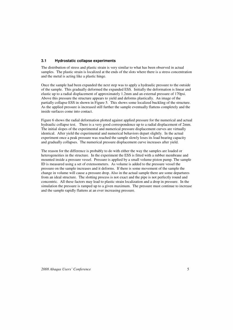
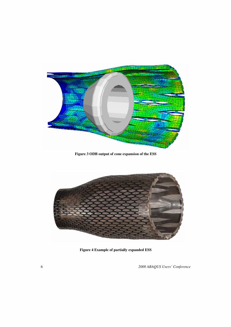
In the actual application of this technology in the field expansion is accomplished by a cone or a
variable expansion tool. Only cone expansions were simulated due to the relative simplicity of the
models. Full representations of the tooling are under development but require very long run times
on the available computers. An example of the cone expansion within Abaqus/CAE is shown in
Figure 3 and a partially expanded piece of real ESS is shown in Figure 4.
Typically it takes 25-35klbs to push a cone through a 4 ½” ESS, the modeled reaction force was
31klbs. This represents a good match between the experimentally measured values and the FEA.
2008 Abaqus Users’ Conference 5
3.1 Hydrostatic collapse experiments
The distribution of stress and plastic strain is very similar to what has been observed in actual
samples. The plastic strain is localized at the ends of the slots where there is a stress concentration
and the metal is acting like a plastic hinge.
Once the sample had been expanded the next step was to apply a hydraulic pressure to the outside
of the sample. This gradually deformed the expanded ESS. Initially the deformation is linear and
elastic up to a radial displacement of approximately 1.2mm and an external pressure of 170psi.
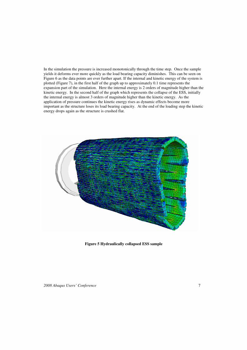
Above this pressure the structure appears to yield and deforms plastically. An image of the
partially collapse ESS in shown in Figure 5. This shows some localized buckling of the structure.
As the applied pressure is increased still further the sample eventually flattens completely and the
inside surfaces come into contact.
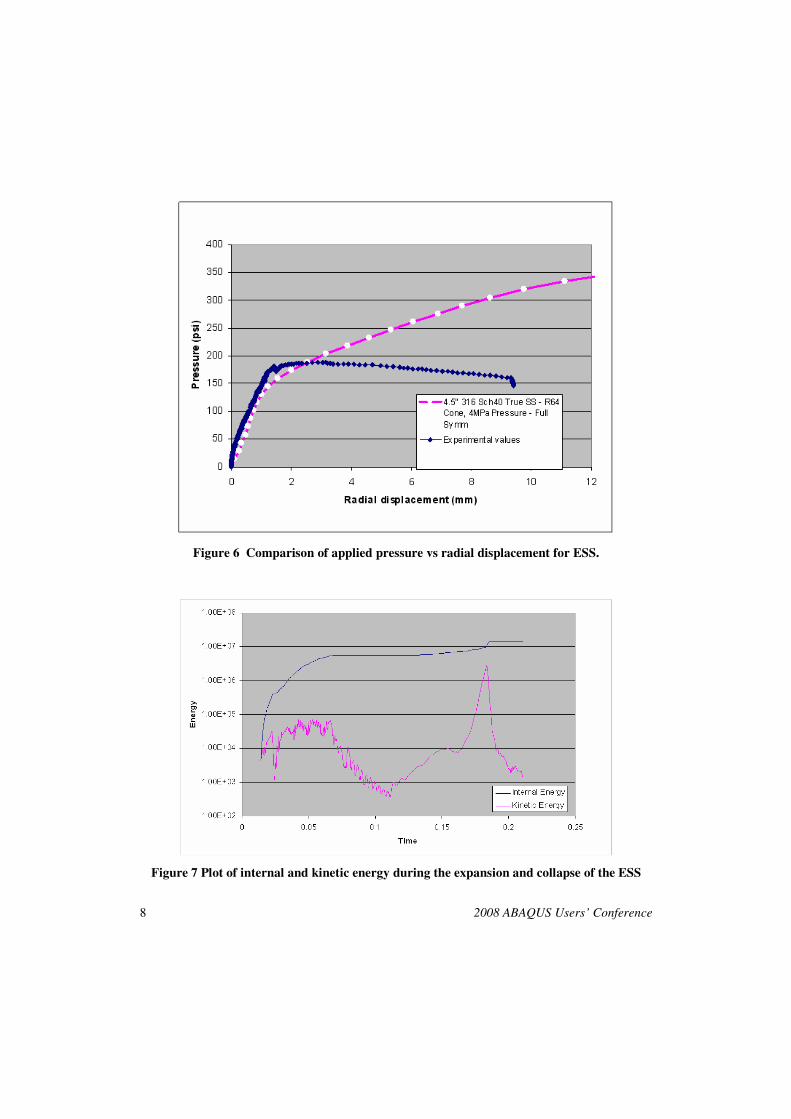
Figure 6 shows the radial deformation plotted against applied pressure for the numerical and actual
hydraulic collapse test. There is a very good correspondence up to a radial displacement of 2mm.
The initial slopes of the experimental and numerical pressure displacement curves are virtually
identical. After yield the experimental and numerical behaviors depart slightly. In the actual
experiment once a peak pressure was reached the sample slowly loses its load bearing capacity
and gradually collapses. The numerical pressure displacement curve increases after yield.
The reason for the difference is probably to do with either the way the samples are loaded or
heterogeneities in the structure. In the experiment the ESS is fitted with a rubber membrane and
mounted inside a pressure vessel. Pressure is applied by a small volume piston pump. The sample
ID is measured using a set of extensometers. As volume is added to the pressure vessel the
pressure on the sample increases and it deforms. If there is some movement of the sample the
change in volume will cause a pressure drop. Also in the actual sample there are some departures
from an ideal structure. The slotting process is not exact and the pipe is not perfectly round and
concentric. All these factors may lead to plastic strain localization and a drop in pressure. In the
simulation the pressure is ramped up to a given maximum. The pressure must continue to increase
and the sample rapidly flattens at an ever increasing pressure.
6 2008 ABAQUS Users’ Conference
Figure 3 ODB output of cone expansion of the ESS
Figure 4 Example of partially expanded ESS
2008 Abaqus Users’ Conference 7
In the simulation the pressure is increased monotonically through the time step. Once the sample
yields it deforms ever more quickly as the load bearing capacity diminishes. This can be seen on
Figure 6 as the data points are ever further apart. If the internal and kinetic energy of the system is
plotted (Figure 7), in the first half of the graph up to approximately 0.1 time represents the
expansion part of the simulation. Here the internal energy is 2 orders of magnitude higher than the
kinetic energy. In the second half of the graph which represents the collapse of the ESS, initially
the internal energy is almost 3 orders of magnitude higher than the kinetic energy. As the
application of pressure continues the kinetic energy rises as dynamic effects become more
important as the structure loses its load bearing capacity. At the end of the loading step the kinetic
energy drops again as the structure is crushed flat.
Figure 5 Hydraulically collapsed ESS sample
8 2008 ABAQUS Users’ Conference
Figure 6 Comparison of applied pressure vs radial displacement for ESS.
Figure 7 Plot of internal and kinetic energy during the expansion and collapse of the ESS
2008 Abaqus Users’ Conference 9
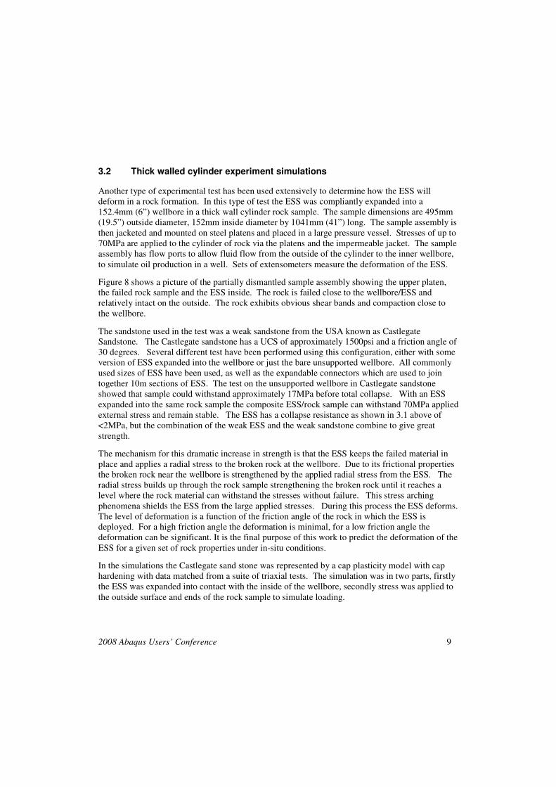
3.2 Thick walled cylinder experiment simulations
Another type of experimental test has been used extensively to determine how the ESS will
deform in a rock formation. In this type of test the ESS was compliantly expanded into a
152.4mm (6”) wellbore in a thick wall cylinder rock sample. The sample dimensions are 495mm
(19.5”) outside diameter, 152mm inside diameter by 1041mm (41”) long. The sample assembly is
then jacketed and mounted on steel platens and placed in a large pressure vessel. Stresses of up to
70MPa are applied to the cylinder of rock via the platens and the impermeable jacket. The sample
assembly has flow ports to allow fluid flow from the outside of the cylinder to the inner wellbore,
to simulate oil production in a well. Sets of extensometers measure the deformation of the ESS.
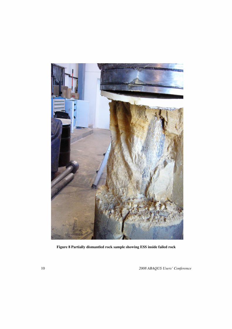
Figure 8 shows a picture of the partially dismantled sample assembly showing the upper platen,
the failed rock sample and the ESS inside. The rock is failed close to the wellbore/ESS and
relatively intact on the outside. The rock exhibits obvious shear bands and compaction close to
the wellbore.
The sandstone used in the test was a weak sandstone from the USA known as Castlegate
Sandstone. The Castlegate sandstone has a UCS of approximately 1500psi and a friction angle of
30 degrees. Several different test have been performed using this configuration, either with some
version of ESS expanded into the wellbore or just the bare unsupported wellbore. All commonly
used sizes of ESS have been used, as well as the expandable connectors which are used to join
together 10m sections of ESS. The test on the unsupported wellbore in Castlegate sandstone
showed that sample could withstand approximately 17MPa before total collapse. With an ESS
expanded into the same rock sample the composite ESS/rock sample can withstand 70MPa applied
external stress and remain stable. The ESS has a collapse resistance as shown in 3.1 above of
<2MPa, but the combination of the weak ESS and the weak sandstone combine to give great
strength.
The mechanism for this dramatic increase in strength is that the ESS keeps the failed material in
place and applies a radial stress to the broken rock at the wellbore. Due to its frictional properties
the broken rock near the wellbore is strengthened by the applied radial stress from the ESS. The
radial stress builds up through the rock sample strengthening the broken rock until it reaches a
level where the rock material can withstand the stresses without failure. This stress arching
phenomena shields the ESS from the large applied stresses. During this process the ESS deforms.
The level of deformation is a function of the friction angle of the rock in which the ESS is
deployed. For a high friction angle the deformation is minimal, for a low friction angle the
deformation can be significant. It is the final purpose of this work to predict the deformation of the
ESS for a given set of rock properties under in-situ conditions.
In the simulations the Castlegate sand stone was represented by a cap plasticity model with cap
hardening with data matched from a suite of triaxial tests. The simulation was in two parts, firstly
the ESS was expanded into contact with the inside of the wellbore, secondly stress was applied to
the outside surface and ends of the rock sample to simulate loading.
10 2008 ABAQUS Users’ Conference
Figure 8 Partially dismantled rock sample showing ESS inside failed rock
2008 Abaqus Users’ Conference 11
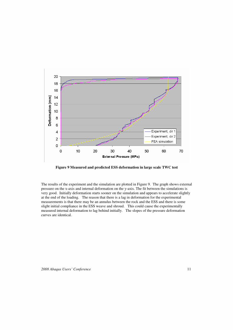
Figure 9 Measured and predicted ESS deformation in large scale TWC test
The results of the experiment and the simulation are plotted in Figure 9. The graph shows external
pressure on the x-axis and internal deformation on the y-axis. The fit between the simulations is
very good. Initially deformation starts sooner on the simulation and appears to accelerate slightly
at the end of the loading. The reason that there is a lag in deformation for the experimental
measurements is that there may be an annulus between the rock and the ESS and there is some
slight initial compliance in the ESS weave and shroud. This could cause the experimentally
measured internal deformation to lag behind initially. The slopes of the pressure deformation
curves are identical.
12 2008 ABAQUS Users’ Conference
4. Conclusions and further work
This work represents our first attempt at using FEA modeling to better understand how the ESS
will respond to applied stresses. It is clear that there is a great deal of further work that could be
done to improve the modeling but the simulations agree very well with both the hydraulic collapse
testing and the large scale thick walled cylinder tests.
Abaqus/Explicit can be applied to many aspects of product testing. It can and is currently being
used for a rapid evaluation of different designs of ESS such as slot patterns, pipe thickness and
metallurgy. In the past, test pieces were used for these types of evaluation which is expensive and
time consuming. Tooling design and optimization is already being developed, again at a great
potential saving.
The most important future application is the simulation of how an ESS deforms in an actual
formation. Models are currently being built to perform these simulations.
5. References
1. Metcalfe, P, and Whitelaw, C, “The Development of the First Expandable Sand Screen,”
OTC 11032, presented at the Offshore Technology Conference Houston, Texas 3-6 May
1999
2. Jones, C., Tollefsen, M., Somerville, J.M., and Hutcheon, R., “Prediction of Skin in
Openhole Sand Control Completions,” SPE 94527, presented at the 6th
European Formation
Damage Conference, Scheveningen, The Netherlands, 25-27th
May 2005
3. Willson, S., Crook, T., Yu, J.G., Stenebraten, J., Gilchrist, J., and Tiffen, D., “Assuring the
Mechanical Integrity of Expandable Sand Screens,” OTC 14314, presented at the Offshore
Technology Conference Houston, Texas 6-9th May 2002