FEA Information Engineering Journal - feaiej
16
ISSN 2167-1273 Volume 3, Issue 01, January 2014 FEA Information Engineering Journal PreProcessing
Transcript of FEA Information Engineering Journal - feaiej

ISSN 2167-1273 Volume 3, Issue 01, January 2014
FEA Information Engineering Journal
PreProcessing
FEA Information Engineering Journal
Aim and Scope FEA Information Engineering Journal (FEAIEJ™) is a monthly published online journal to cover the latest Finite Element Analysis Technologies. The journal aims to cover previous noteworthy published papers and original papers. All published papers are peer reviewed in the respective FEA engineering fields. Consideration is given to all aspects of technically excellent written information without limitation on length. All submissions must follow guidelines for publishing a paper, or periodical. If a paper has been previously published, FEAIEJ requires written permission to reprint, with the proper acknowledgement give to the publisher of the published work. Reproduction in whole, or part, without the express written permissio of FEA Information Engineering Journal, or the owner of of the copyright work, is strictly prohibited. FEAIJ welcomes unsolicited topics, ideas, and articles. Monthly publication is limited to no more then five papers, either reprint, or original. Papers will be archived on www.feaiej.com For information on publishing a paper original or reprint contact [email protected] Subject line: Journal Publication
Cover: Fig. 6: Forhead Impact Zone and the lowest point on its meridian An Automated Process for Interior Head Impact Analysis Thanassis Fokilidis, Anneli Hoegberg, Antonis Perifanis BETA CAE Systems SA, VOLVO CAR Corporation, BETA CAE Systems SA
2 Fea Information Engineering Journal January 2014
FEA Information Engineering Journal
TABLE OF CONTENTS
Publications are © to LS-DYNA 2013 9th European Users‘ Conference Efficient Work-flow through Automation in PRIMER Richard Sturt, Miles Thornton, Alasdair Parkes, Chris Archer (Arup) Interfacing Seamless LS-DYNA Integration in ANSYS Workbench Environment Wolfgang Lietz (Cadfem GmbH) Philip Ho (Livermore Software Technology Corporation) Increasing Productivity with LS-DYNA in Crash & Safety Simulation” Sri Rama Murty (ESI Software) Andrea Gittens (ESI Software Germany GmbH) An Automated Process for Interior Head Impact Analysis Thanassis Fokilidis, Anneli Hoegberg, Antonis Perifanis BETA CAE Systems SA, VOLVO CAR Corporation, BETA CAE Systems SA
All contents are copyright © to the publishing company, author or respective company. All rights reserved.
3 Fea Information Engineering Journal January 2014
© 2013 Copyright by Arup
Efficient Work-flow through Automation in PRIMER
Richard Sturt, Miles Thornton, Alasdair Parkes, Chris Archer (Arup)
Introduction and Motivation
Automation of CAE processes is the top current challenge for many CAE departments. The motivations for automation are:
Speed: With CAE now on the critical path for product development in many industries, it is essential to speed up the creation, debugging and updating of models. Automation with PRIMER offers a powerful route to reducing pre-processing time.
Accuracy: Further time-savings can be achieved through the consistency and accuracy of PRIMER-based processes, leading to reduction of errors.
Integration: To fully realise the benefits of design in the digital environment, a smooth and integrated process is required with flow of data from CAD through CAE model build to results reports.
LS-DYNA® is the leading solver for many nonlinear analysis applications such as crashworthiness and occupant protection. From a work-flow point of view, these applications are characterised by very demanding requirements for setting up the models, often mirroring the protocols adopted in physical testing. Such processes offer considerable challenges to automation; not only are the protocols time-consuming to reproduce in the analysis environment, but the models must be manipulated without corrupting or losing any of the LS-DYNA data. PRIMER combines a thorough understanding of the LS-DYNA data with specialised and customisable functions for model set-up, and thus provides the opportunity for a fast, efficient and accurate workflow.
PRIMER Automation Technologies
Primer includes many built-in functions to automate common processes. Additionally, the user may create their own automation processes, by recording macros and/or writing JavaScripts; and they can chain together separate process elements into a continuous automatic process. These technologies will be reviewed briefly.
Applications
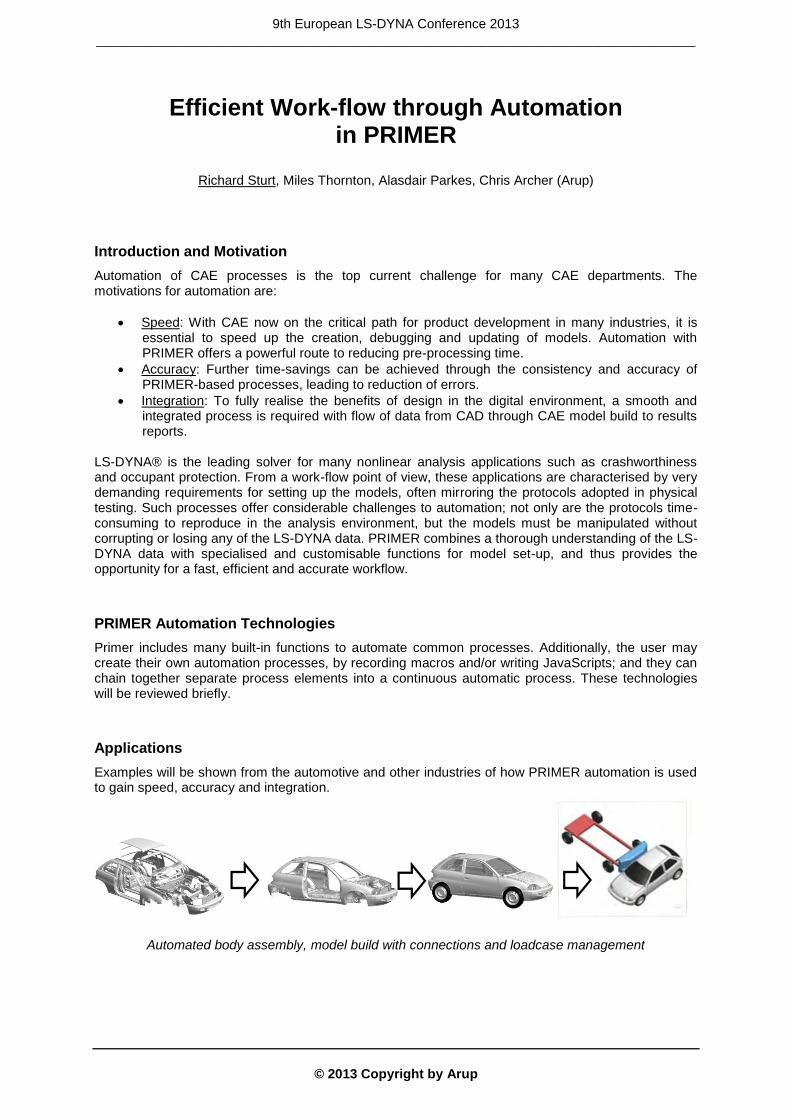
Examples will be shown from the automotive and other industries of how PRIMER automation is used to gain speed, accuracy and integration.
Automated body assembly, model build with connections and loadcase management
9th European LS-DYNA Conference 2013 _________________________________________________________________________________
© 2013 Copyright by Arup
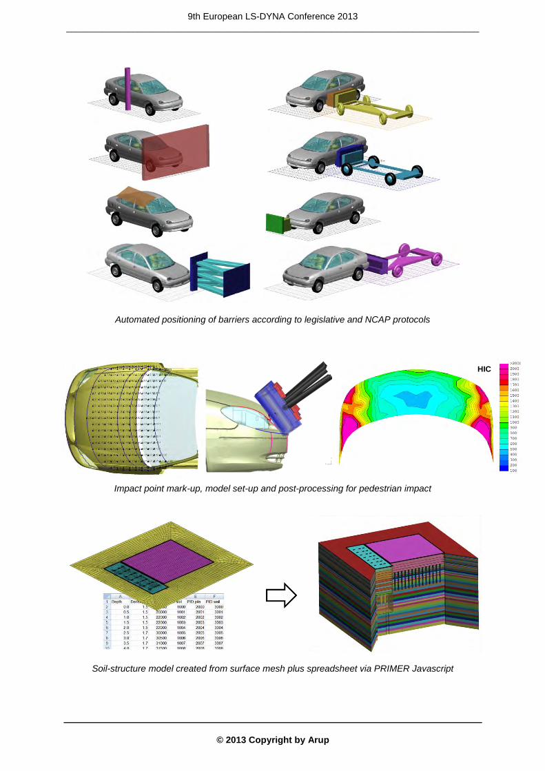
Automated positioning of barriers according to legislative and NCAP protocols
Impact point mark-up, model set-up and post-processing for pedestrian impact
Soil-structure model created from surface mesh plus spreadsheet via PRIMER Javascript
HIC
9th European LS-DYNA Conference 2013 _________________________________________________________________________________
© 2013 Copyright by Arup
Interfacing Seamless LS-DYNA Integration in ANSYS Workbench Environment
Wolfgang Lietz (Cadfem GmbH)
Philip Ho (Livermore Software Technology Corporation)
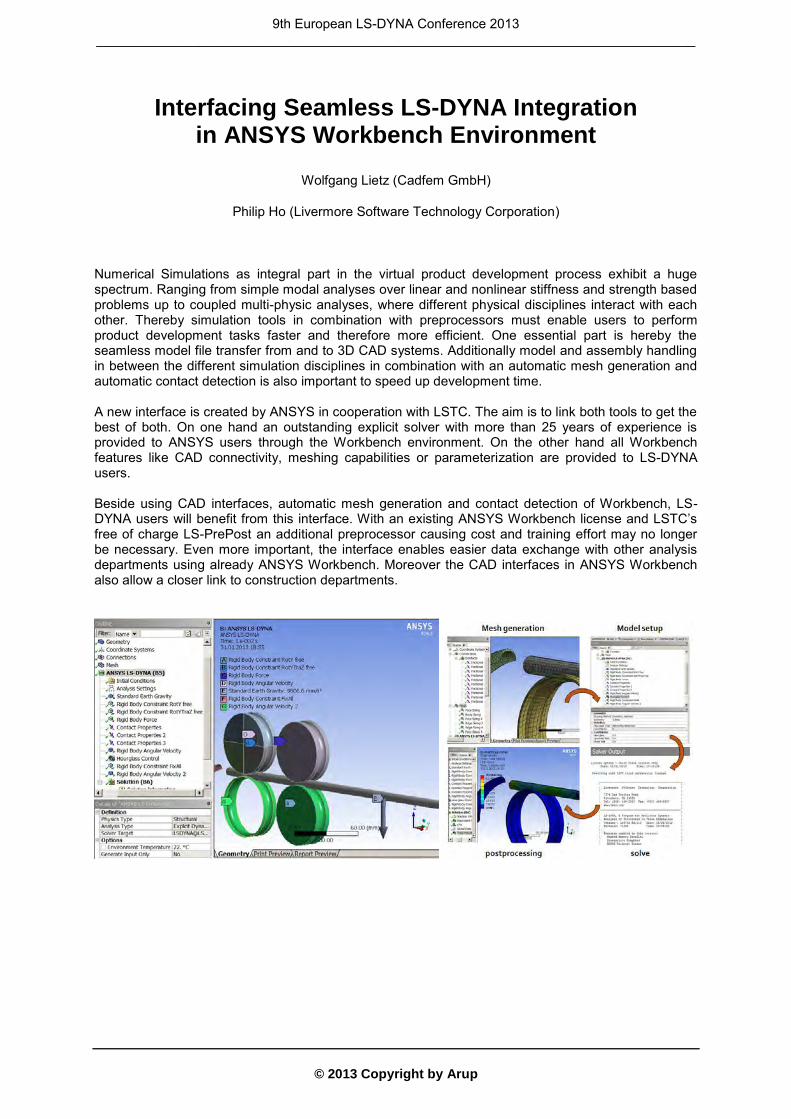
Numerical Simulations as integral part in the virtual product development process exhibit a huge spectrum. Ranging from simple modal analyses over linear and nonlinear stiffness and strength based problems up to coupled multi-physic analyses, where different physical disciplines interact with each other. Thereby simulation tools in combination with preprocessors must enable users to perform product development tasks faster and therefore more efficient. One essential part is hereby the seamless model file transfer from and to 3D CAD systems. Additionally model and assembly handling in between the different simulation disciplines in combination with an automatic mesh generation and automatic contact detection is also important to speed up development time. A new interface is created by ANSYS in cooperation with LSTC. The aim is to link both tools to get the best of both. On one hand an outstanding explicit solver with more than 25 years of experience is provided to ANSYS users through the Workbench environment. On the other hand all Workbench features like CAD connectivity, meshing capabilities or parameterization are provided to LS-DYNA users. Beside using CAD interfaces, automatic mesh generation and contact detection of Workbench, LS-DYNA users will benefit from this interface. With an existing ANSYS Workbench license and LSTC’s free of charge LS-PrePost an additional preprocessor causing cost and training effort may no longer be necessary. Even more important, the interface enables easier data exchange with other analysis departments using already ANSYS Workbench. Moreover the CAD interfaces in ANSYS Workbench also allow a closer link to construction departments.
9th European LS-DYNA Conference 2013 _________________________________________________________________________________
© 2013 Copyright by Arup
Increasing Productivity with LS-DYNA in Crash & Safety Simulation”
Sri Rama Murty (ESI Software)
Andrea Gittens (ESI Software Germany GmbH)
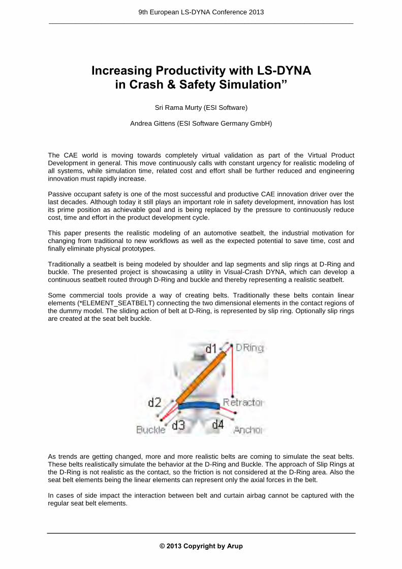
The CAE world is moving towards completely virtual validation as part of the Virtual Product Development in general. This move continuously calls with constant urgency for realistic modeling of all systems, while simulation time, related cost and effort shall be further reduced and engineering innovation must rapidly increase. Passive occupant safety is one of the most successful and productive CAE innovation driver over the last decades. Although today it still plays an important role in safety development, innovation has lost its prime position as achievable goal and is being replaced by the pressure to continuously reduce cost, time and effort in the product development cycle. This paper presents the realistic modeling of an automotive seatbelt, the industrial motivation for changing from traditional to new workflows as well as the expected potential to save time, cost and finally eliminate physical prototypes. Traditionally a seatbelt is being modeled by shoulder and lap segments and slip rings at D-Ring and buckle. The presented project is showcasing a utility in Visual-Crash DYNA, which can develop a continuous seatbelt routed through D-Ring and buckle and thereby representing a realistic seatbelt. Some commercial tools provide a way of creating belts. Traditionally these belts contain linear elements (*ELEMENT_SEATBELT) connecting the two dimensional elements in the contact regions of the dummy model. The sliding action of belt at D-Ring, is represented by slip ring. Optionally slip rings are created at the seat belt buckle.
As trends are getting changed, more and more realistic belts are coming to simulate the seat belts. These belts realistically simulate the behavior at the D-Ring and Buckle. The approach of Slip Rings at the D-Ring is not realistic as the contact, so the friction is not considered at the D-Ring area. Also the seat belt elements being the linear elements can represent only the axial forces in the belt. In cases of side impact the interaction between belt and curtain airbag cannot be captured with the regular seat belt elements.
9th European LS-DYNA Conference 2013 _________________________________________________________________________________

© 2013 Copyright by Arup
However the creation of the continuous seatbelt is not easy to model and only few commercially available preprocessing tools are given this option. Due to modifications done in modeling (meshing) with belts using shell elements a possibility of slackness in the belt and also creation of warped elements around the buckle and D-Ring always exist. The introduced project and related study target creation of a continuous belt using Visual-Crash DYNA, one of several preprocessing applications in Visual-Environment. Utilizing the belt creation features and meshing algorithms, a continuous belt creation is made. Furthermore, methods to create prescribed motion to the belt expecting removal of the slackness and methods to simulate belt routing through solver features were also investigated. At the end of the study key results are compared on sled models built with traditional belt modeling and the continuous belt modeling.
9th European LS-DYNA Conference 2013 _________________________________________________________________________________
© 2013 Copyright by Arup
An Automated Process for Interior Head Impact Analysis
Thanassis Fokilidis, Anneli Hoegberg, Antonis Perifanis
BETA CAE Systems SA, VOLVO CAR Corporation, BETA CAE Systems SA
1 Abstract During the last decade, the Occupant Protection legislation requirements on interior safety properties of automobiles have become considerably more demanding. The US standard laboratory test procedure FMVSS201U regulates the tests for the head protection against the event of its impact on the upper interior roof. The procedure involves the identification of the most critical target zones and headform target angles. To minimize the need for physical tests, the product performance evaluations are, as far as possible, performed with numerical simulations involving CAE software. However, covering all possible load cases would require an infinite number of simulations. In order to automate the generation of input data and to assist in finding the critical load parameters, Volvo Cars Safety Centre and BETA CAE Systems employed a process that involves ANSA pre-processor and μETA post-processor, extended with special tools. This automated process starts with the model file input to ANSA and concludes with the assessment of the LS-DYNA results within μΕΤΑ, requiring minimum human interaction. An advanced algorithm, for the automatic headform positioning, which identifies the areas where the maximum vertical angle can be reached, has been developed. The process also involves a robustness analysis for each target point, and thus reduces the uncertainty of the problem. This has been successfully deployed within Volvo Cars Safety Centre, leading to great reduction of modelling time
2 Introduction One of the most substantial issues that Safety engineers have to deal with is the occupant protection during a car accident. In particular, head protection against the event of its impact on the upper roof zone of the vehicle, demands complex safety analysis processes. As a result, the simulations in CAE software have been increased in order to cover the continuously increasing number of the corresponding loadcases. The need for automated and robust tools is mandatory to minimize the human interaction. Volvo Corporation in collaboration with BETA CAE Systems SA has employed a process that simulates a complete test for the Interior Head Impact Analysis according to the FMVSS201U test procedure. The process begins in ANSA pre-processor with the automatic identification of the Target Points in the Upper Roof Zone of the vehicle. It continues, using the same software, with the positioning of the headform impactor on the identified Targets and the creation of the corresponding keyword files which are solved by LS-DYNA. At the end, the process involves the presentation and the evaluation of the respective results in μETA post-processor.
9th European LS-DYNA Conference 2013 _________________________________________________________________________________
© 2013 Copyright by Arup
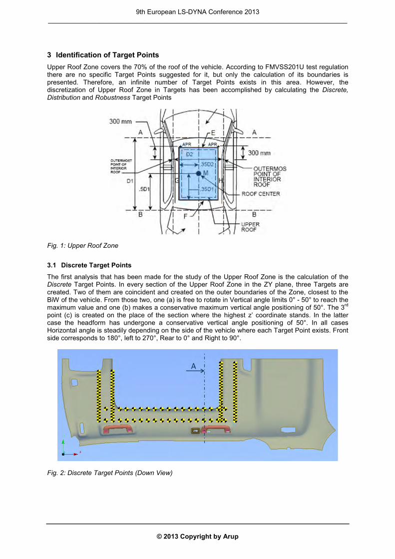
3 Identification of Target Points Upper Roof Zone covers the 70% of the roof of the vehicle. According to FMVSS201U test regulation there are no specific Target Points suggested for it, but only the calculation of its boundaries is presented. Therefore, an infinite number of Target Points exists in this area. However, the discretization of Upper Roof Zone in Targets has been accomplished by calculating the Discrete, Distribution and Robustness Target Points
Fig. 1: Upper Roof Zone
3.1 Discrete Target Points
The first analysis that has been made for the study of the Upper Roof Zone is the calculation of the Discrete Target Points. In every section of the Upper Roof Zone in the ZY plane, three Targets are created. Two of them are coincident and created on the outer boundaries of the Zone, closest to the BiW of the vehicle. From those two, one (a) is free to rotate in Vertical angle limits 0° - 50° to reach the maximum value and one (b) makes a conservative maximum vertical angle positioning of 50°. The 3rd point (c) is created on the place of the section where the highest z’ coordinate stands. In the latter case the headform has undergone a conservative vertical angle positioning of 50°. In all cases Horizontal angle is steadily depending on the side of the vehicle where each Target Point exists. Front side corresponds to 180°, left to 270°, Rear to 0° and Right to 90°.
Fig. 2: Discrete Target Points (Down View)
9th European LS-DYNA Conference 2013 _________________________________________________________________________________
© 2013 Copyright by Arup
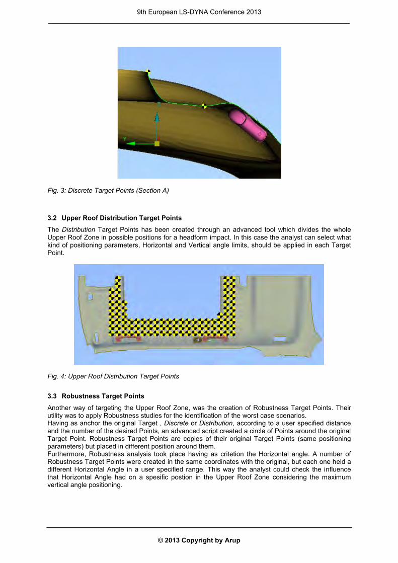
Fig. 3: Discrete Target Points (Section A)
3.2 Upper Roof Distribution Target Points
The Distribution Target Points has been created through an advanced tool which divides the whole Upper Roof Zone in possible positions for a headform impact. In this case the analyst can select what kind of positioning parameters, Horizontal and Vertical angle limits, should be applied in each Target Point.
Fig. 4: Upper Roof Distribution Target Points
3.3 Robustness Target Points
Another way of targeting the Upper Roof Zone, was the creation of Robustness Target Points. Their utility was to apply Robustness studies for the identification of the worst case scenarios. Having as anchor the original Target , Discrete or Distribution, according to a user specified distance and the number of the desired Points, an advanced script created a circle of Points around the original Target Point. Robustness Target Points are copies of their original Target Points (same positioning parameters) but placed in different position around them. Furthermore, Robustness analysis took place having as critetion the Horizontal angle. A number of Robustness Target Points were created in the same coordinates with the original, but each one held a different Horizontal Angle in a user specified range. This way the analyst could check the influence that Horizontal Angle had on a spesific postion in the Upper Roof Zone considering the maximum vertical angle positioning.
9th European LS-DYNA Conference 2013 _________________________________________________________________________________
© 2013 Copyright by Arup
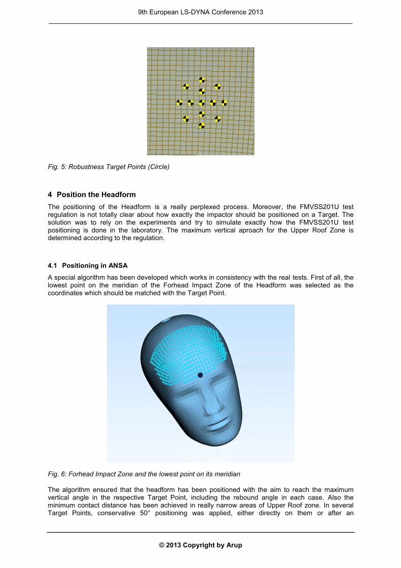
Fig. 5: Robustness Target Points (Circle)
4 Position the Headform The positioning of the Headform is a really perplexed process. Moreover, the FMVSS201U test regulation is not totally clear about how exactly the impactor should be positioned on a Target. The solution was to rely on the experiments and try to simulate exactly how the FMVSS201U test positioning is done in the laboratory. The maximum vertical aproach for the Upper Roof Zone is determined according to the regulation.
4.1 Positioning in ANSA
A special algorithm has been developed which works in consistency with the real tests. First of all, the lowest point on the meridian of the Forhead Impact Zone of the Headform was selected as the coordinates which should be matched with the Target Point.
Fig. 6: Forhead Impact Zone and the lowest point on its meridian The algorithm ensured that the headform has been positioned with the aim to reach the maximum vertical angle in the respective Target Point, including the rebound angle in each case. Also the minimum contact distance has been achieved in really narrow areas of Upper Roof zone. In several Target Points, conservative 50° positioning was applied, either directly on them or after an
9th European LS-DYNA Conference 2013 _________________________________________________________________________________
© 2013 Copyright by Arup
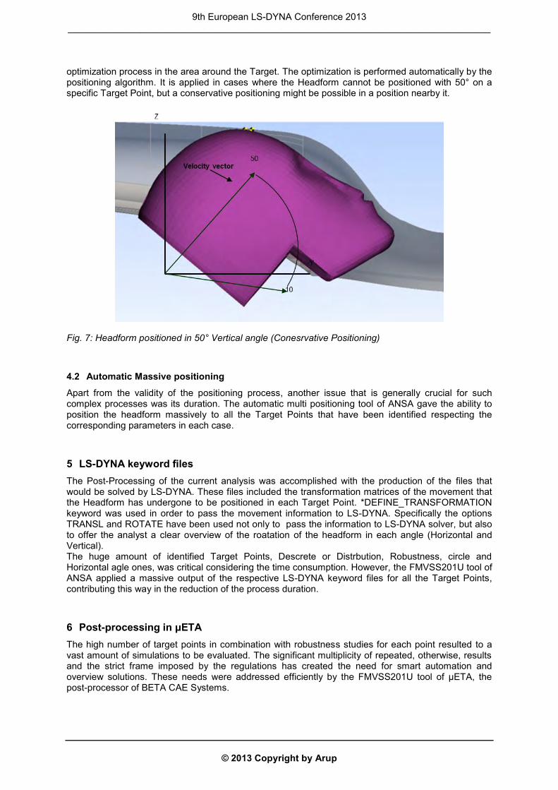
optimization process in the area around the Target. The optimization is performed automatically by the positioning algorithm. It is applied in cases where the Headform cannot be positioned with 50° on a specific Target Point, but a conservative positioning might be possible in a position nearby it.
Fig. 7: Headform positioned in 50° Vertical angle (Conesrvative Positioning)
4.2 Automatic Massive positioning
Apart from the validity of the positioning process, another issue that is generally crucial for such complex processes was its duration. The automatic multi positioning tool of ANSA gave the ability to position the headform massively to all the Target Points that have been identified respecting the corresponding parameters in each case.
5 LS-DYNA keyword files The Post-Processing of the current analysis was accomplished with the production of the files that would be solved by LS-DYNA. These files included the transformation matrices of the movement that the Headform has undergone to be positioned in each Target Point. *DEFINE_TRANSFORMATION keyword was used in order to pass the movement information to LS-DYNA. Specifically the options TRANSL and ROTATE have been used not only to pass the information to LS-DYNA solver, but also to offer the analyst a clear overview of the roatation of the headform in each angle (Horizontal and Vertical). The huge amount of identified Target Points, Descrete or Distrbution, Robustness, circle and Horizontal agle ones, was critical considering the time consumption. However, the FMVSS201U tool of ANSA applied a massive output of the respective LS-DYNA keyword files for all the Target Points, contributing this way in the reduction of the process duration.
6 Post-processing in μETA The high number of target points in combination with robustness studies for each point resulted to a vast amount of simulations to be evaluated. The significant multiplicity of repeated, otherwise, results and the strict frame imposed by the regulations has created the need for smart automation and overview solutions. These needs were addressed efficiently by the FMVSS201U tool of μETA, the post-processor of BETA CAE Systems.
9th European LS-DYNA Conference 2013 _________________________________________________________________________________
© 2013 Copyright by Arup
6.1 Post-processing results in 2d and 3d
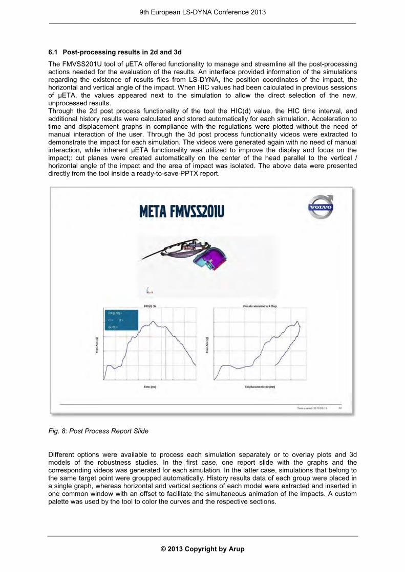
The FMVSS201U tool of μETA offered functionality to manage and streamline all the post-processing actions needed for the evaluation of the results. An interface provided information of the simulations regarding the existence of results files from LS-DYNA, the position coordinates of the impact, the horizontal and vertical angle of the impact. When HIC values had been calculated in previous sessions of μETA, the values appeared next to the simulation to allow the direct selection of the new, unprocessed results. Through the 2d post process functionality of the tool the HIC(d) value, the HIC time interval, and additional history results were calculated and stored automatically for each simulation. Acceleration to time and displacement graphs in compliance with the regulations were plotted without the need of manual interaction of the user. Through the 3d post process functionality videos were extracted to demonstrate the impact for each simulation. The videos were generated again with no need of manual interaction, while inherent μETA functionality was utilized to improve the display and focus on the impact;: cut planes were created automatically on the center of the head parallel to the vertical / horizontal angle of the impact and the area of impact was isolated. The above data were presented directly from the tool inside a ready-to-save PPTX report.
Fig. 8: Post Process Report Slide Different options were available to process each simulation separately or to overlay plots and 3d models of the robustness studies. In the first case, one report slide with the graphs and the corresponding videos was generated for each simulation. In the latter case, simulations that belong to the same target point were groupped automatically. History results data of each group were placed in a single graph, whereas horizontal and vertical sections of each model were extracted and inserted in one common window with an offset to facilitate the simultaneous animation of the impacts. A custom palette was used by the tool to color the curves and the respective sections.
9th European LS-DYNA Conference 2013 _________________________________________________________________________________
© 2013 Copyright by Arup
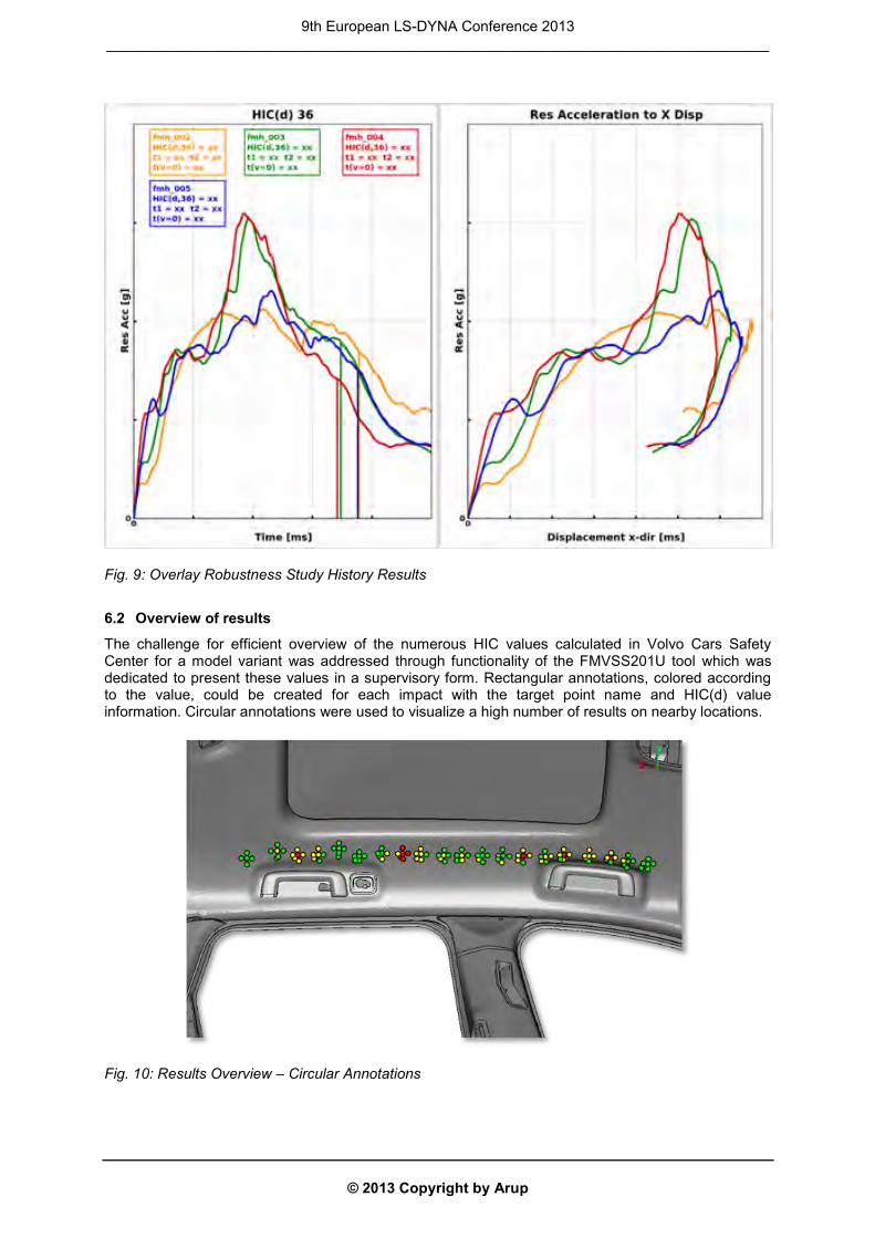
Fig. 9: Overlay Robustness Study History Results
6.2 Overview of results
The challenge for efficient overview of the numerous HIC values calculated in Volvo Cars Safety Center for a model variant was addressed through functionality of the FMVSS201U tool which was dedicated to present these values in a supervisory form. Rectangular annotations, colored according to the value, could be created for each impact with the target point name and HIC(d) value information. Circular annotations were used to visualize a high number of results on nearby locations.
Fig. 10: Results Overview – Circular Annotations
9th European LS-DYNA Conference 2013 _________________________________________________________________________________
© 2013 Copyright by Arup
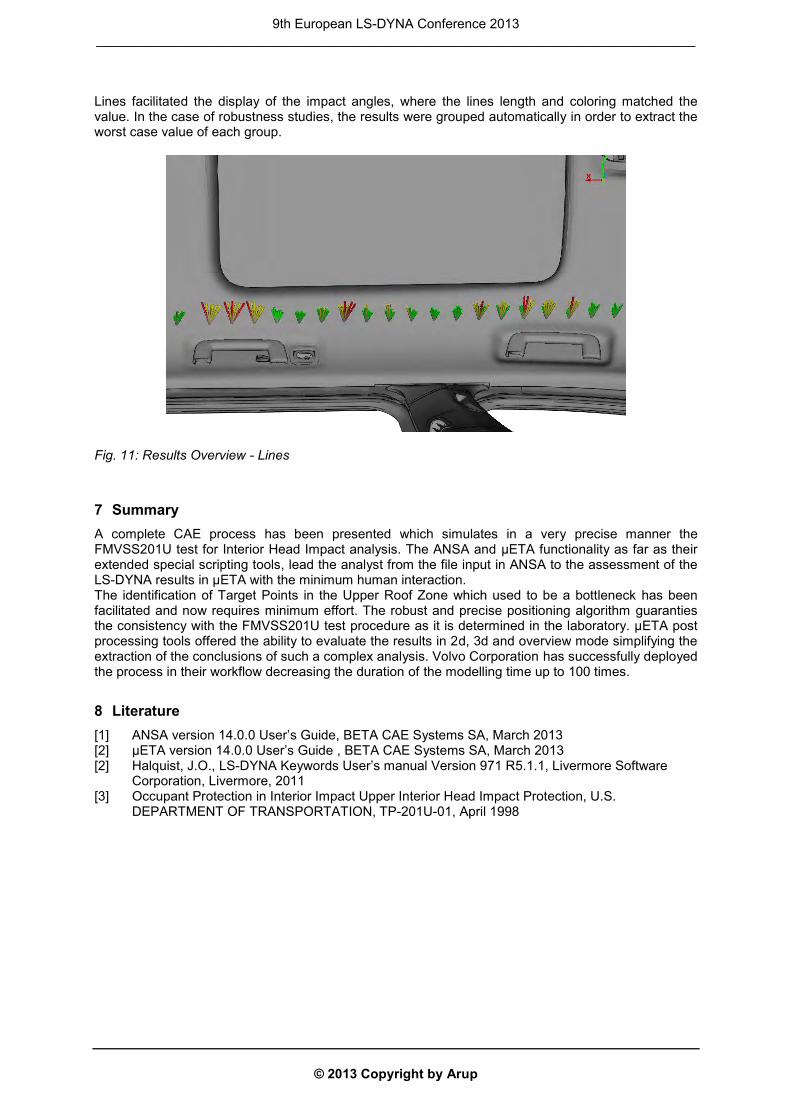
Lines facilitated the display of the impact angles, where the lines length and coloring matched the value. In the case of robustness studies, the results were grouped automatically in order to extract the worst case value of each group.
Fig. 11: Results Overview - Lines
7 Summary A complete CAE process has been presented which simulates in a very precise manner the FMVSS201U test for Interior Head Impact analysis. The ANSA and μETA functionality as far as their extended special scripting tools, lead the analyst from the file input in ANSA to the assessment of the LS-DYNA results in μETA with the minimum human interaction. The identification of Target Points in the Upper Roof Zone which used to be a bottleneck has been facilitated and now requires minimum effort. The robust and precise positioning algorithm guaranties the consistency with the FMVSS201U test procedure as it is determined in the laboratory. μETA post processing tools offered the ability to evaluate the results in 2d, 3d and overview mode simplifying the extraction of the conclusions of such a complex analysis. Volvo Corporation has successfully deployed the process in their workflow decreasing the duration of the modelling time up to 100 times.
8 Literature [1] ANSA version 14.0.0 User’s Guide, BETA CAE Systems SA, March 2013 [2] μETA version 14.0.0 User’s Guide , BETA CAE Systems SA, March 2013 [2] Halquist, J.O., LS-DYNA Keywords User’s manual Version 971 R5.1.1, Livermore Software
Corporation, Livermore, 2011 [3] Occupant Protection in Interior Impact Upper Interior Head Impact Protection, U.S.
DEPARTMENT OF TRANSPORTATION, TP-201U-01, April 1998
9th European LS-DYNA Conference 2013 _________________________________________________________________________________