
FE Review –Basic Circuits - College of Engineering Exam Review... · FE Review –Basic Circuits...
80
FE Review – Basic Circuits William Hageman 11-18-2014
Transcript of FE Review –Basic Circuits - College of Engineering Exam Review... · FE Review –Basic Circuits...

FE Review – Basic Circuits
William Hageman
11-18-2014

FE topics
14. Electricity, Power, and Magnetism 7–11
A. Electrical fundamentals (e.g., charge,
current, voltage, resistance, power, energy)
B. Current and voltage laws (Kirchhoff, Ohm)
C. DC circuits
D. Equivalent circuits (series, parallel, Norton’s
theorem, Thevenin’s theorem)
E. Capacitance and inductance
F. AC circuits (e.g., real and imaginary
components, complex numbers, power factor,
reactance and impedance)
G. Measuring devices (e.g., voltmeter,
ammeter, wattmeter)
General FE
Electricity and Magnetism 3–5
A. Charge, current, voltage, power, and energy
B. Current and voltage laws (Kirchhoff, Ohm)
C. Equivalent circuits (series, parallel)
D. AC circuits
E. Motors and generators
Mechanical FE
Engineering Sciences 5–8
A. Work, energy, and power
B. Material properties and selection
C. Charge, energy, current, voltage, and power
Industrial FE
Engineering Sciences 4–6
A. Applications of vector analysis (e.g., statics)
B. Basic dynamics (e.g., friction, force, mass, acceleration, momentum)
C. Work, energy, and power (as applied to particles or rigid bodies)
D. Electricity and current and voltage laws (e.g., charge, energy,
current, voltage, power, Kirchhoff, Ohm)
Chemical FE

Topics to Be Covered
• DC Circuits and Analysis– DC Voltage
– DC Current
– Power
– Resistance
– Resistivity
– Ohms Law
– Series and Parallel Combinations of Resistors
– Voltage and Current Dividers
– Capacitors
– Inductors
– Kirchhoff’s Laws
– Simple Resistive Circuit Solving
– Delta-Wye Transforms
– Superposition
– Source Transforms and
Thevenin/Norton Equivalent Circuits
– Maximum Power Transfer
– RC and LC Transients
• AC Circuits– AC Waveforms
– Sine and Cosine Relations
– RMS Values
– Phasor Transforms
– Phase Angles
– Impedance
– Ohm’s Law for AC circuits
– Complex Power
– Resonance
– Transformers

DC Circuits and Analysis

Definition of Voltage
• Separating electric charge requires energy. The potential energy per unit charge created by charge separation is VOLTAGE. It is often referred to as electrical potential.
where v = voltage in volts,
w = energy in joules
q = charge in coulombs
It is a Δ quantity… i.e. measured at one point relative to another… most typically
relative to the electrical potential of the Earth (ground).

Definition of Current
• Flowing charges create electrical effects. The
rate of charge flow is called CURRENT
where i = current in amperes,
q = charge in coulombs
t = time in seconds
We typically think of current flowing through wires in our circuits much like
water through pipes

Electrical Power
• The power supplied or dissipated in a circuit element can be found from the following relation:
• A negative power denotes power being supplied by the element, positive power denotes power being dissipated by the element
ivP =

Resistance
• Resistance is the ability of a circuit element to
impede current flow. It is denoted by R.
• Resistance is measured in Ohms (Ω). Energy is
dissipated in a resistor and converted into
heat.
R

Resistivity
• Resistivity (ρ) is a material property that
governs resistance. The resistivity of a
material along with its physical geometry
determine its resistance. It is defined in terms
of units of (Ohm * meters)
A
lR ρ=
l
A

Ohm’s Law
• Ohm’s Law provides a relationship between
the voltage dropped across a resistive element
and the current flowing through it.
iRv =By convention, the
ohm’s law voltage
drops in the direction
of current flow

Power dissipated in a Resistor
Recall that: Power = v*i
Using Ohm’s Law, the power dissipated in a resistor can be re-written multiple ways:
P = (i*R)*i = i2R
P = v*(v/R) = v2/R
These expressions hold true regardless of sign convention… Power is always dissipated in a resistor.

Combinations of Resistors
• Separate Resistors in a circuit can be combined to create a simplified equivalent resistance
• Resistors in Series• When resistors are connected in series (end to end) they can simply be added
...4321 ++++= RRRRReq

Combinations of Resistors
• Resistors in Parallel• When resistors are connected in Parallel (side to side)
they add in the inverse
...11111
4321
++++=RRRRReq

Example FE Problem
If Req=10.8Ω, what is R2?
a) 12Ω
b) 20Ω
c) 8Ω
d) 18Ω

Solving DC Circuits
• We have covered voltage and current (the two
parameters we wish to find throughout an
electrical circuit) as well as basic circuit
elements.
• This allows us to begin to construct and model
basic resistive circuits
• We will need some basic circuit theorems in
order to solve these circuits.

Circuit Terminology

Practice
How Many Nodes? How Many Essential Nodes?
How Many Branches? How Many Essential Branches?
How Many Meshes?
Kirchoff’s Current Law
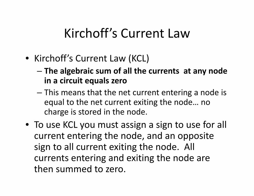
• Kirchoff’s Current Law (KCL)
– The algebraic sum of all the currents at any node
in a circuit equals zero
– This means that the net current entering a node is equal to the net current exiting the node… no charge is stored in the node.
• To use KCL you must assign a sign to use for all current entering the node, and an opposite sign to all current exiting the node. All currents entering and exiting the node are then summed to zero.

Kirchoff’s Voltage Law
• Kirchoff’s Voltage Law (KVL)
– The algebraic sum of all the voltage drops around
any closed path in a circuit is equal to zero
– A closed path in a circuit is a path that takes you from a starting node back to that node without passing through any intermediate node more than once
– To use KVL, simply find a closed path and sum the voltage drops you encounter and set the sum equal to zero

Systematic Approach
• By immediately identifying the essential nodes and branches of a circuit, we can immediately go about systematically solving the circuit.
• Using KVL and KCL on essential nodes and branches is a perfectly good and valid technique for circuit solving
• However, there are new variables called node voltages and mesh currents that let us further reduce the number of equations needed for solving a circuit

Node-Voltage Method
• 1st Steps in Node-Voltage Method
– Make a neat layout of your circuit with no branches crossing over
– Mark the essential nodes
– Pick one of the essential nodes to be your reference node and mark it. (typically the node with the most branches)
– Define the node voltages (voltages from reference node to other essential nodes)

Node-Voltage Method Continued
• With the node voltages labeled in your circuit
you are ready to generate your node-voltage
equations
– This is done by writing each of the essential
branch currents leaving the essential nodes in
terms of the node voltages and then summing
them to zero in accordance with Kirchoff’s current
law.

Example of N-V method
There are three branch currents coming out of node 1:
The current (1) through the 1Ω resistor and 10V source
The current (2) through the 5Ω resistor
The current (3) through the 2Ω resistor
These can be written in terms of the node voltages, v1 and v2.
0251
10 2111 =Ω
−+Ω
+Ω
− vvvVv
(1) (2)(3)

Finishing Example
• This same process can be used to produce the
N-V equation for node 2.
• These two equations have two unknowns, v1
and v2, thus the two node voltages can be
calculated and the branch currents
determined from them.
02102
212 =−+− vvv
Vv
Vv
91.10
09.9
2
1
==

Exercise
• Find the two node voltage equations that
would allow us to find v1 and v2.

Solution
Node with v1:
Node with v2:
0612
1 211 =−++−k
vv
k
vmA
06
46
212 =+++−k
vmA
k
vv
mAk
vkk
v 16
1
6
1
12
121 =
−
+
mAkk
vk
v 46
1
6
1
6
121 −=
++
−
Vvv 1223 21 =−
Vvv 242 21 −=+−
242 21 += vv
( ) Vvv 1222423 22 =−+
Vv 604 2 −=
Vv 152 −=Vv 12303 1 =+
Vv 61 −=

Example FE Exam Problem
Find Vo in the circuit.
a) 3.33 V
b) 8.25 V
c) 9.33 V
d) 2.25 V

Additional Techniques

Voltage Divider
• The voltage divider is a simple way to find the
voltage across two resistors in series.
+=
21
11 RR
Rvv s
+=
21
22 RR
Rvv s

Current Divider
• The current divider allow you to find the
current flowing through one of two parallel
resistors
+=
21
21 RR
Rii s
+=
21
12 RR
Rii s
Delta-Wye Transforms
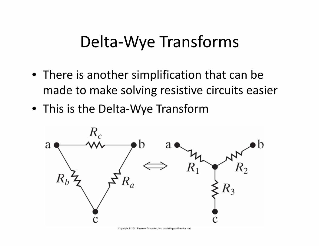
• There is another simplification that can be
made to make solving resistive circuits easier
• This is the Delta-Wye Transform
Transform Equations
cba
ba
cba
ac
cba
cb
RRR
RRR
RRR
RRR
RRR
RRR
++=
++=
++=
3
2
1
3
133221
2
133221
1
133221
R
RRRRRRR
R
RRRRRRR
R
RRRRRRR
c
b
a
++=
++=
++=
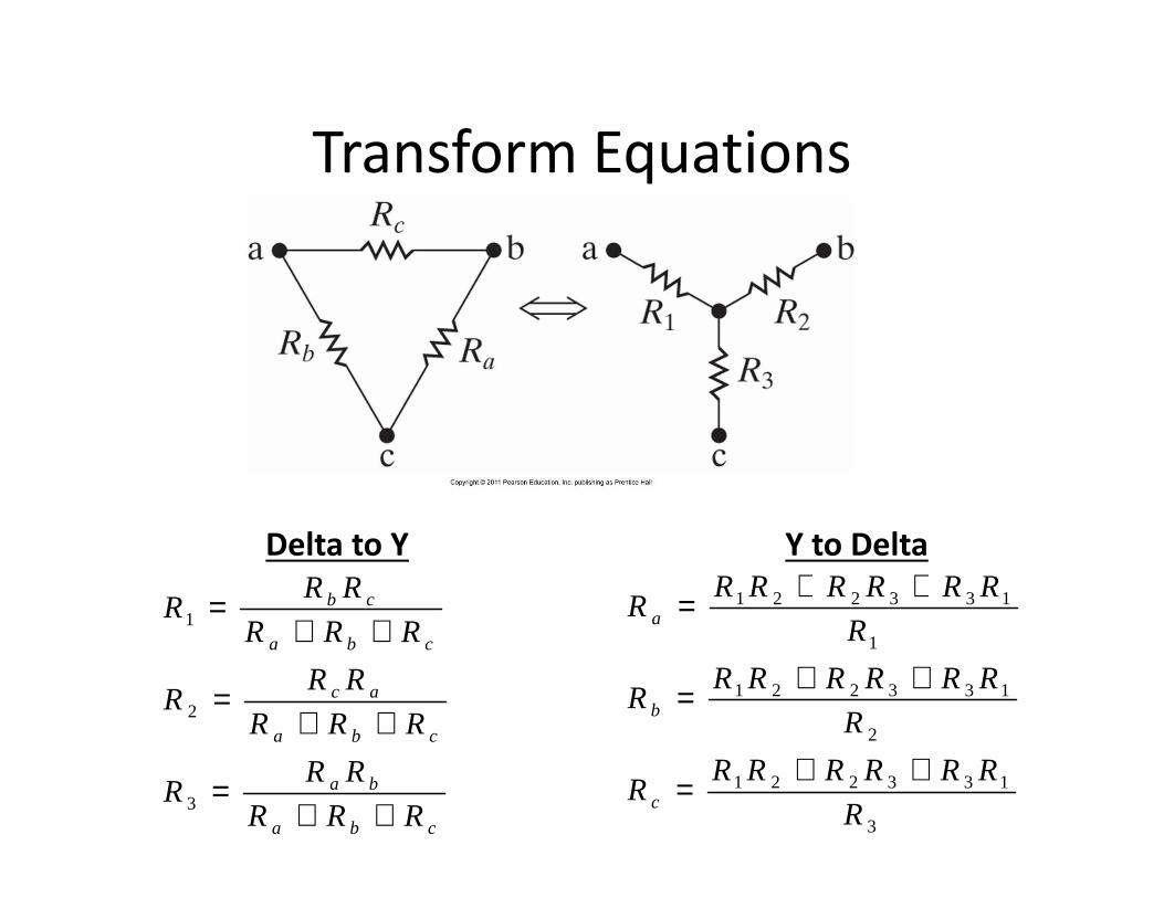
Delta to Y Y to Delta

Superposition
• All linear systems obey the principle of superposition.
• This means that whenever a linear system is driven by multiple sources, the total response of the system is the sum of the responses to each individual source
• This principle is used in all areas of engineering and physics and is of course useful in Circuit Theory

What does this mean for solving
circuits?• The value of voltage or current relating to any element in a circuit can be
thought of as the sum of the voltages and currents resulting on that
element from each of the independent sources in the circuit individually.
=
+v2’ v2’’
v2
v1’ v1’’
v1
'''
'''
222
111
iii
iii
+=+=
'''
'''
444
333
iii
iii
+=+=
'''
'''
222
111
vvv
vvv
+=+=

Uses for superposition
• Superposition is highly useful if you have a circuit that you have already solved that is altered by adding a new source of some type.
• All you need to do is deactivate all the original sources and find the values resulting from your new source
• The true altered values in your circuit are just the original values plus what results from the new source
• Also very useful when analyzing multiple signals in a system. You find found the output for each signal individually and then sum the results to find that full solution.

Example
With only 24V source:
With only 40mA source:
VVVvo 8.4125
2524
258020
2524' =
=
++=
( ) VmAmAvo 8.010025
)100(2540100//2540'' −=
+−=−=
Vvvv ooo 48.08.4''' =−=+=

Source Transformations
– Another method like Delta-Wye and
Parallel/Series combinations to simplify circuits
– Can switch between equivalent sources: a voltage
source with series resistor or current source with
parallel resistor

How to Transform
• Each of the two equivalent sources must
produce the same current through any load
connected across the source.
RLRL
Ls
L
s
RR
Ri
RR
v
+=
+
Lsload RR
RiI
+= (current divider)L
sload RR
vI
+=
Riv ss =R
vi ss =OR

Source Transform Example
What is Power of 6V source?
i = (19.2V-6V)/16 = 0.825A P = i*v = 0.825A*6V = 4.95W
i

Example FE Exam Problem
Find I in the circuit.
a) 8 A
b) -4 A
c) 0 A
d) 4 A

Thevenin Equivalent Circuits

Terminal Behavior
• We are often interested in looking at the
behavior of an electrical circuit at it’s output
terminals.
• If a load is hooked to a circuit, how does the
circuit behave relative to the load?
• If the circuit is made of linear elements, the
entire circuit can be simplified into a Thevenin
(or Norton) Equivalent circuit.
Justification
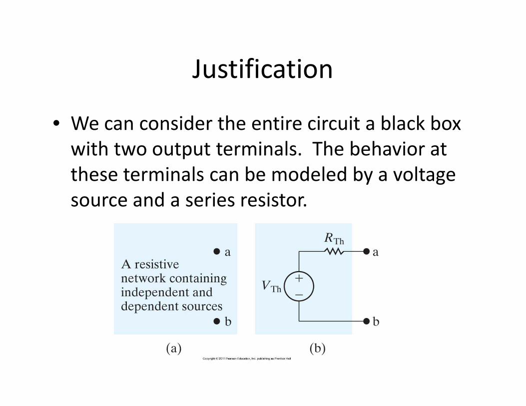
• We can consider the entire circuit a black box
with two output terminals. The behavior at
these terminals can be modeled by a voltage
source and a series resistor.

Finding the Thevenin Voltage
• If we look at the terminal with no load
attached (open circuit output), the voltage
between the output terminals is VTh.
With an open circuit, no current flows
This means no voltage drop across RTh
Hence Vab = VTh

Finding Thevinen Resistance
• Now lets look at what happens when the output is short circuited
• If we can find the short circuit current and have already found VTh, then we can easily calculate RTh
isc
sc
ThTh
Th
Thsc
i
VR
R
Vi
=
=
Power Transfer
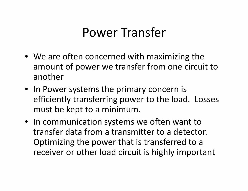
• We are often concerned with maximizing the amount of power we transfer from one circuit to another
• In Power systems the primary concern is efficiently transferring power to the load. Losses must be kept to a minimum.
• In communication systems we often want to transfer data from a transmitter to a detector. Optimizing the power that is transferred to a receiver or other load circuit is highly important
Maximum Power Transfer
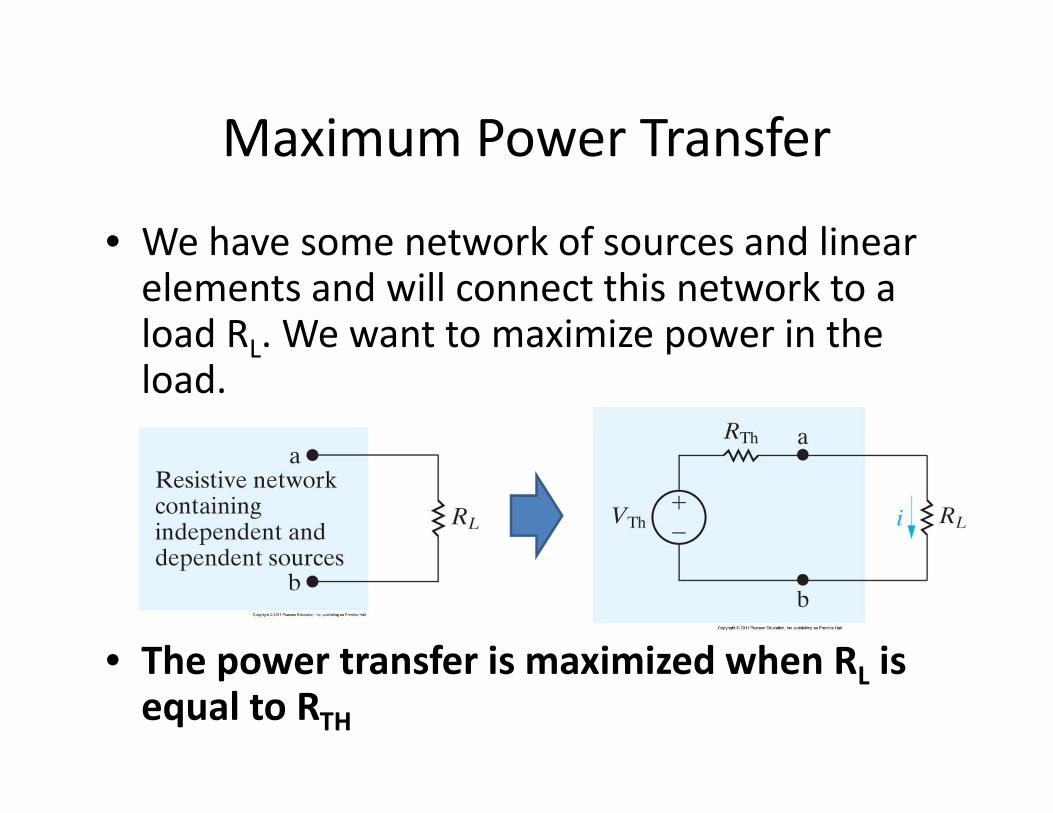
• We have some network of sources and linear elements and will connect this network to a load RL. We want to maximize power in the load.
• The power transfer is maximized when RL is
equal to RTH

Example FE Problem
Determine the maximum power that can be delivered to the load
resistor RL in the circuit shown.
a) 2 mW
b) 10 mW
c) 4 mW
d) 8 mW

RL and RC Circuits
Inductors
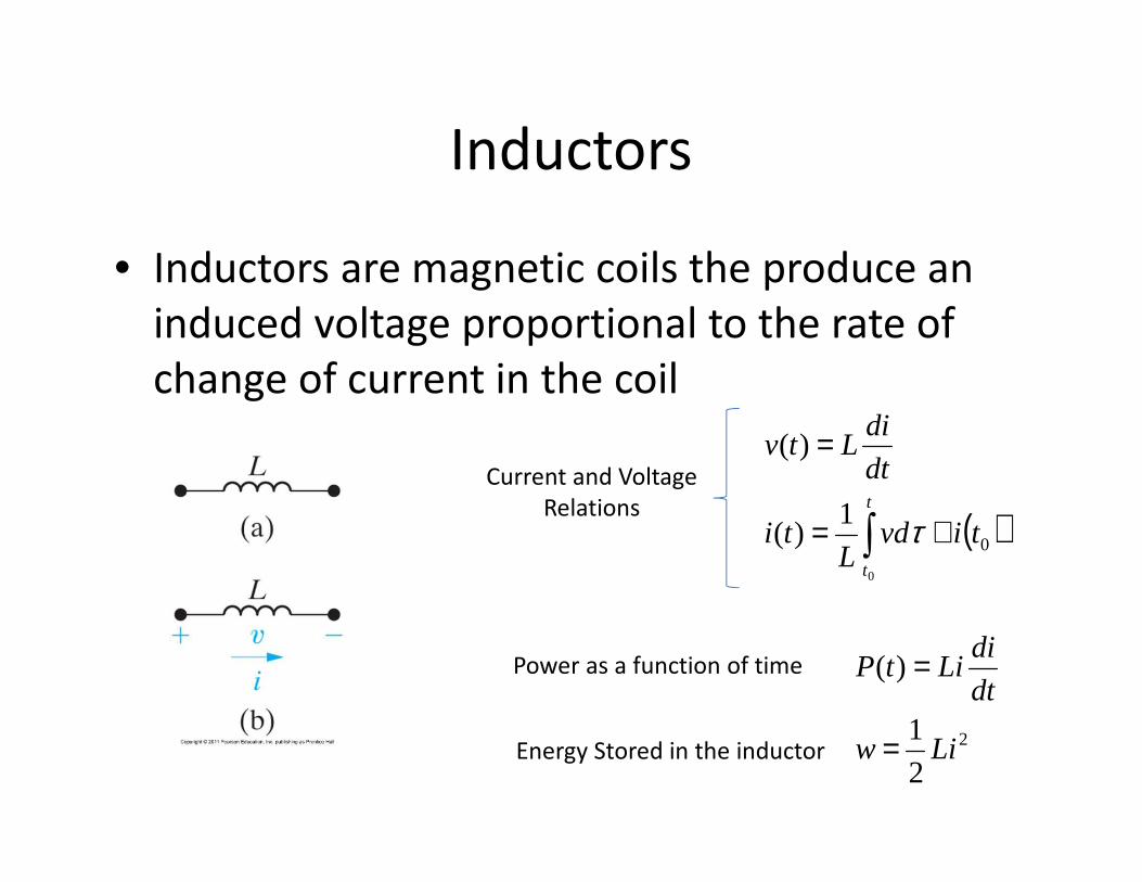
• Inductors are magnetic coils the produce an
induced voltage proportional to the rate of
change of current in the coil
( )∫ +=
=
t
t
tivdL
ti
dt
diLtv
0
0
1)(
)(
τ
Current and Voltage
Relations
2
2
1
)(
Liw
dt
diLitP
=
=Power as a function of time
Energy Stored in the inductor

The Capacitor
• A capacitor is a circuit component represented
by the letter C
• Capacitance is measured in Farads
– Typical values are in the pF to μF range
– A 1F capacitor is extremely large
• The symbol for a capacitor is shown below:
Sign
Convention

Capacitor Current and Voltage
Relations
• The current and voltage relations for a
capacitor are opposite to those of the
inductor
( )∫ +=
=
t
t
tivdL
ti
dt
diLtv
0
0
1)(
)(
τ ( )∫ +=
=
t
t
tvidC
tv
dt
dvCti
0
0
1)(
)(
τ
Inductor: Capacitor:

Power and Energy Relations
• Similarly, the power and energy storage
relationships for a capacitor are reversed in
terms of voltage and current from those of the
inductor:
2
2
1
)(
Liw
dt
diLitP
=
=
2
2
1
)(
Cvw
dt
dvCvtP
=
=Power as a function
of time
Stored Energy
Inductor Capacitor

Series and Parallel Combinations of
Inductors and Capacitors
• Inductors add in series much like resistors:
dt
diLv 11 =
( )dt
diL
dt
diLLLvvvv eq=++=++= 321321
dt
diLv 22 =
dt
diLv 33 =
neq LLLLLL +++++= ...4321

Parallel Inductors
( )∫ +=t
t
tivdL
i0
011
1
1 τ ( )∫ +=t
t
tivdL
i0
022
2
1 τ ( )∫ +=t
t
tivdL
i0
033
3
1 τ
321 iiii ++=
( ) ( ) ( )030201321 0
111tititivd
LLLi
t
t
+++
++= ∫ τ
1
4321
1...
1111−
+++++=
neq LLLLL
L)(...)()()( 002010 titititi n+++=
Combinations of Capacitors
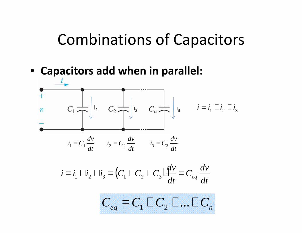
• Capacitors add when in parallel:
neq CCCC +++= ...21
321 iiii ++=i1 i2 i3
dt
dvCi 11 =
( )dt
dvC
dt
dvCCCiiii eq=++=++= 321321
dt
dvCi 22 =
dt
dvCi 33 =

Series Combinations of Capacitors
( )∫ +=t
t
tvidC
v0
011
1
1 τnvvvv +++= ...21
( ) ( ) ( )00201
21
...
1...
11
0
tvtvtv
idCCC
v
n
t
tn
++++
+++= ∫ τ
neq CCCC
1...
111
21
+++=
)(...)()()( 002010 tvtvtvtv n+++=
Inductors add in the inverse when in parallel, just like resistors
( )∫ +=t
t
tvidC
v0
022
2
1 τ
( )∫ +=t
t
nn
n tvidC
v0
0
1 τCn
vn
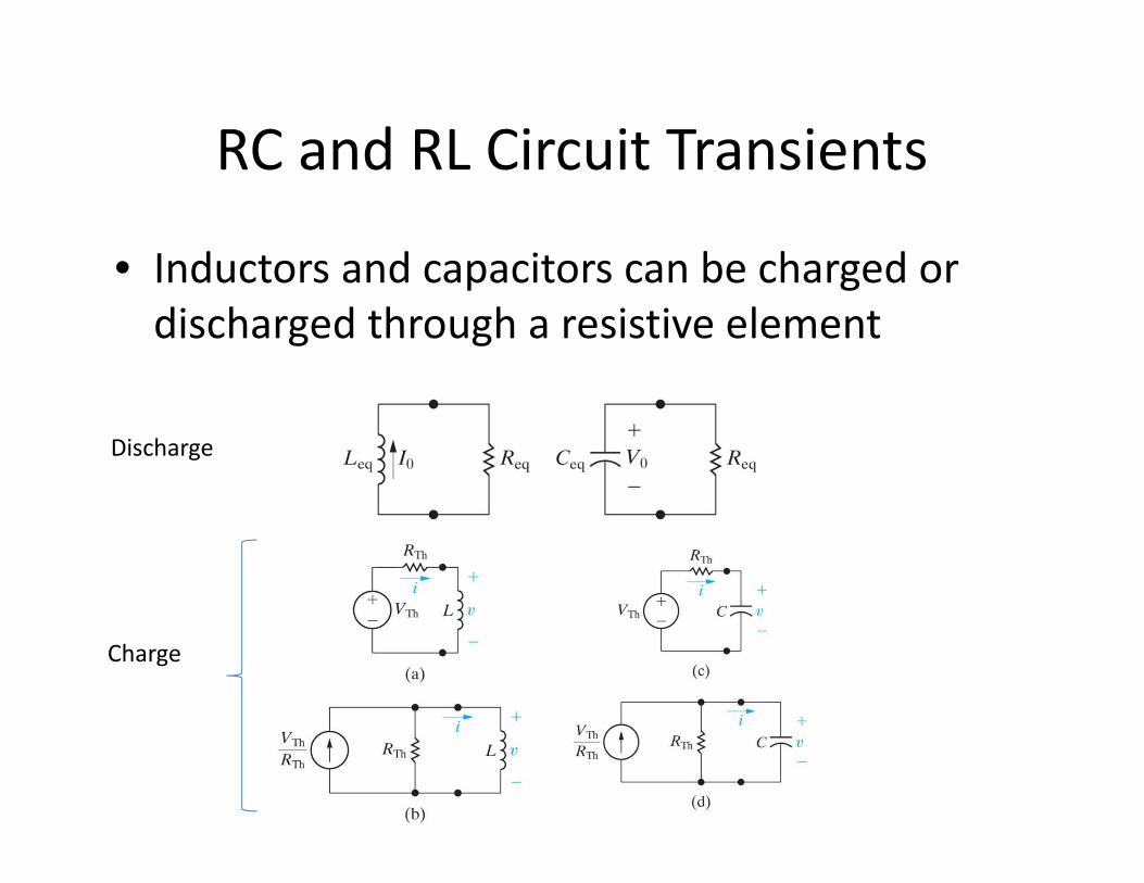
RC and RL Circuit Transients
• Inductors and capacitors can be charged or
discharged through a resistive element
Discharge
Charge

General Form of RC and RL Response
• All off these simple RC and RL circuits have the
same form of response:
( )( )
τ0
)(tt
finalinitialfinal eXXXtX−−
−+=
•X can be current or voltage in either the inductor or capacitor
•Tau is the time constant:
•τ=RC for RC circuit
•τ=L/R for RL circuit

Example FE problem
What is the equivalent inductance of the circuit?
a) 9.5 mH
b) 2.5 mH
c) 6.5 mH
d) 3.5 mH

Example Problem #2
What is the voltage across the 10 mH inductor expressed as a function of time?
a)
b)
c)
d)

AC Circuits and Analysis

AC Waveforms
• AC waveforms are sinusoidal and can be
described by either a sine or cosine
( )φω += tVtv m cos)(Vm = Amplitude
ω = angular frequency (equal to 2πf or 2π/T)
φ = phase constant

Sine-Cosine Relations
• The following are useful relationships for AC
circuits:
)2
cos()2
cos()sin(
)2
sin()2
sin()cos(
πωπωω
πωπωω
+−=−=
−−=+=
ttt
ttt

RMS Values
• AC sinusoids have an average of zero, so we
use RMS (root of the mean squared function)
to get a measure for effective average value.
( )( )∫+
+=Tt
t
mrms dttVT
V0
0
2cos1 φω
2m
rms
VV =

Phasors and Phasor Transform
• We use Euler’s Identity to express sinusoidal
functions in the complex –number domain.
θθθ sincos je j ±=±Euler’s Identity
φωφωφω jtjm
tjmm eeVeVtVv ℜ=ℜ=+= + )()cos(
The Phasor Representation or Phasor Transform of a Sinusoidal waveform:
)cos( φωφ +== tVPeV mj
mV

Impedance
• Impedance (Z) is the complex analog to simple
resistance.
IV Z= Ohm’s Law for AC Circuits
Circuit Element Impedance Reactance
Resistor R -
Inductor jωL ωL
Capacitor -j/ωC -1/ωC
Reactance is the imaginary part of the Impedance

Kirchhoff’s Laws with AC circuits
• All of Kirchhoff’s Laws still hold with the
phasor transform
– Just sum complex currents and voltages in either
the polar or rectangular form
• Impedances simply sum when in series and
sum in the inverse when in parallel (just like
resistors)

FE exam problem
What is the current Io in the circuit?
a)
b)
c)
d)

Transformers
• Two coils are wound on a single core to ensure
magnetic coupling

Ideal Transformer
• For an ideal transformer the voltages and currents through each winding are related as shown below:
• N1=number of winding in coil 1
• N2=number of winding in coil 2
• V1= voltage across coil 1
• V2= voltage across coil 2
• I1 = Current through coil 1
• I2 = Current through coil 2
2
2
1
1
NN
VV =2211 NN II =

Voltage Polarity in an Ideal
Transformer
The four circuits below show the dot convention and the
relative voltage polarity and direction of current
Voltage that is positive at a dotted terminal results in a
voltage that is positive at the other dotted terminal
Current flowing into a dotted terminal should result in
current flowing out of the other dotted terminal
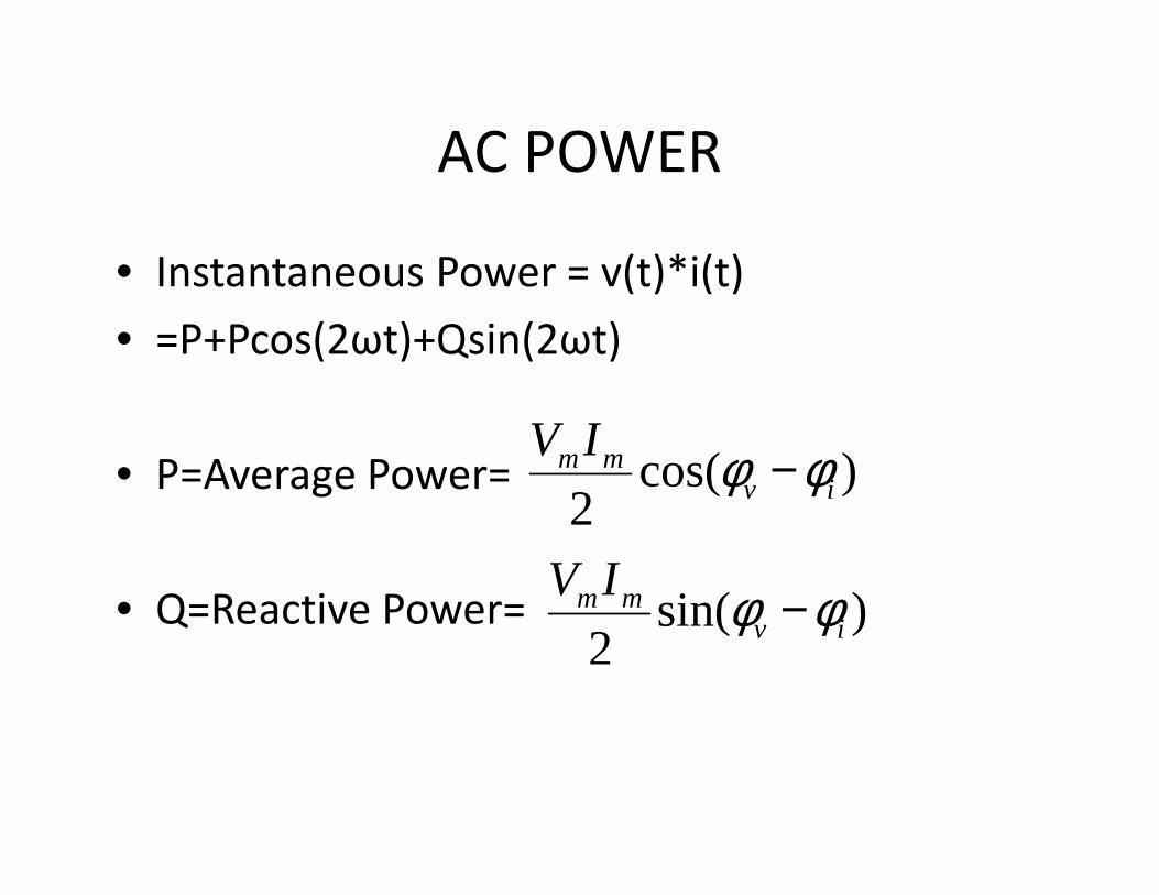
AC POWER
• Instantaneous Power = v(t)*i(t)
• =P+Pcos(2ωt)+Qsin(2ωt)
• P=Average Power=
• Q=Reactive Power=
)cos(2 iv
mmIV φφ −
)sin(2 iv
mmIV φφ −
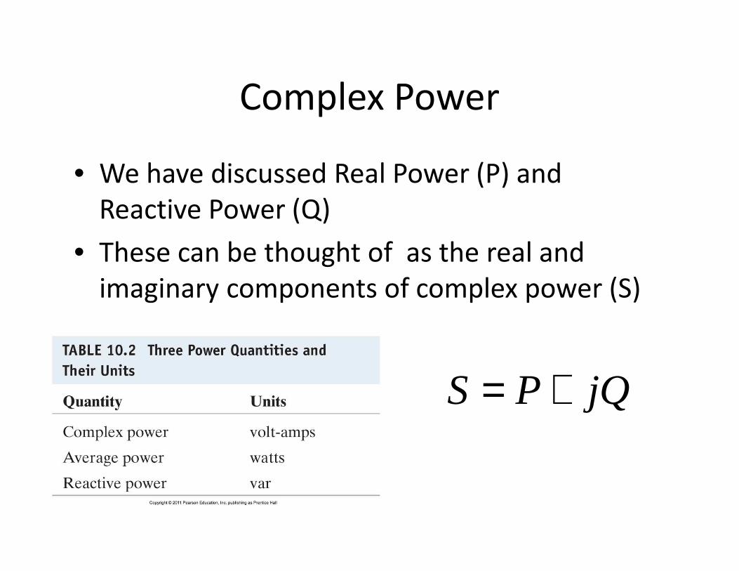
Complex Power
• We have discussed Real Power (P) and
Reactive Power (Q)
• These can be thought of as the real and
imaginary components of complex power (S)
jQPS +=

Apparent Power
• When plotted in the complex plane, Complex
Power can be though of as the result of the
addition of perpendicular P and Q.
• The magnitude of the complex power |S| is
known as Apparent Power
)( iv φφθ −=

Meaning of Apparent Power
• Apparent Power is the amount of Power that must be generated in order to supply a given amount of average power
• If the circuit has reactive elements (which any power network will, such as power lines, generator windings, etc.) There will be a reactive element to the total power.
• If |Q|>0, then the amount of power that must be supplied to drive a circuit that is dissipating a certain amount of real power (P) is greater than P.
• Q can be balanced by compensating inductance with capacitance, making the power factor [cos(φv-φi)]=1
• With proper balancing the amount of apparent power needed to provide a given average power to a load can be minimized
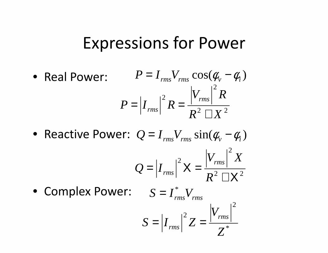
Expressions for Power
• Real Power:
• Reactive Power:
• Complex Power:
)cos( ivrmsrmsVIP φφ −=
22
2
2
XR
RVRIP
rms
rms +==
)sin( ivrmsrmsVIQ φφ −=
rmsrmsVIS *=
*
2
2
Z
VZIS
rms
rms ==
22
2
2
Χ+=Χ=
R
XVIQ
rms
rms
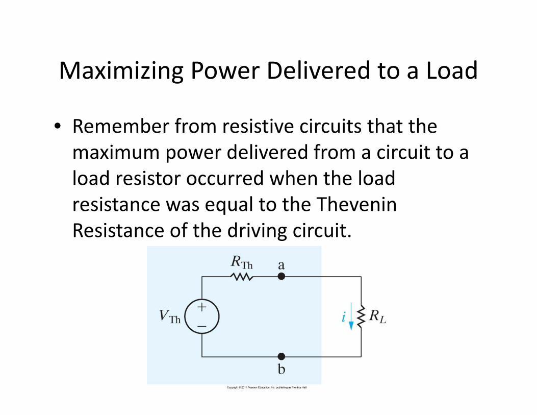
Maximizing Power Delivered to a Load
• Remember from resistive circuits that the
maximum power delivered from a circuit to a
load resistor occurred when the load
resistance was equal to the Thevenin
Resistance of the driving circuit.

Maximizing Power Transfer with
complex circuits
With circuits containing reactive elements, maximum power is transferred when
the load impedance is equal to the complex conjugate of the Thevenin
Equivalent Impedance
*ThL ZZ =
L
Th
R
VP
2
max 4
1=
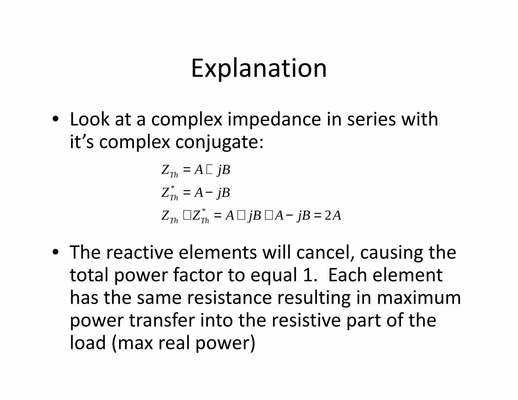
Explanation
• Look at a complex impedance in series with it’s complex conjugate:
• The reactive elements will cancel, causing the total power factor to equal 1. Each element has the same resistance resulting in maximum power transfer into the resistive part of the load (max real power)
AjBAjBAZZ
jBAZ
jBAZ
ThTh
Th
Th
2*
*
=−++=+
−=
+=