FE Electrical Report 2005-2006 - Andy...
27
1 FE Electrical Report 2005-2006 By: Chris Dudasik, Tianyi Li, and Jeff Schvey TAM 492 – Professor Ruina Third Draft: 5/12/06 Electrical Overview - Introduction The electrical system of a robot is equivalent to the nervous system of a human. The robot uses its senses and stored knowledge to make decisions in order to achieve certain goals – in this case, walking. Our robot uses information from limit switch and potentiometer sensor inputs, as well as state information stored in its memory, to send out appropriate output signals to LEDs, solenoids, and the motor controller. This semester saw the introduction of analog inputs, digital outputs, solenoids, launch control, new ideas for long term changes, new approaches to solve problems, and the discovery and solution of a wide variety of small problems. The report to follow details these things. For more information about the robot walk cycle, the basic functionality of the microcontroller, batteries, or general electrical theory, please see the Fe Electrical Team Report – Spring 2005 or the Fe Mechanical Team Report. Our theme this year was threefold: more control, better feedback, and greater reliability. We added control by implementing electromechanical systems such as the solenoid hip locking mechanism to constrain the leg swing and help regulate leg motion. We increased feedback by adding new sensors such as the analog potentiometers and better limit switches. These sensors detected with better accuracy what state our robot was in at all times. Lastly we improved reliability by creating a standardized launch sequence with a laser line up system and pre-launch switch to ensure a consistent angle of launch every time.
Transcript of FE Electrical Report 2005-2006 - Andy...
1
FE Electrical Report 2005-2006 By: Chris Dudasik, Tianyi Li, and Jeff Schvey
TAM 492 – Professor Ruina
Third Draft: 5/12/06
Electrical Overview - Introduction The electrical system of a robot is equivalent to the nervous system of a human. The
robot uses its senses and stored knowledge to make decisions in order to achieve certain goals –
in this case, walking. Our robot uses information from limit switch and potentiometer sensor
inputs, as well as state information stored in its memory, to send out appropriate output signals to
LEDs, solenoids, and the motor controller. This semester saw the introduction of analog inputs,
digital outputs, solenoids, launch control, new ideas for long term changes, new approaches to
solve problems, and the discovery and solution of a wide variety of small problems. The report
to follow details these things. For more information about the robot walk cycle, the basic
functionality of the microcontroller, batteries, or general electrical theory, please see the Fe
Electrical Team Report – Spring 2005 or the Fe Mechanical Team Report.
Our theme this year was threefold: more control, better feedback, and greater reliability.
We added control by implementing electromechanical systems such as the solenoid hip locking
mechanism to constrain the leg swing and help regulate leg motion. We increased feedback by
adding new sensors such as the analog potentiometers and better limit switches. These sensors
detected with better accuracy what state our robot was in at all times. Lastly we improved
reliability by creating a standardized launch sequence with a laser line up system and pre-launch
switch to ensure a consistent angle of launch every time.
2
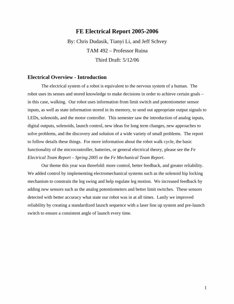
Sensor Overview The Fe Walking Robot progresses through its determined walk cycle by first sampling
both analog and digital values from its sensors, and secondly choosing the correct course of
action based on its software coding. The basic walk cycle relies on only four sensors: two tactile
sensors placed on the feet, a potentiometer at the hip, and a potentiometer on the telescoping leg.
The two tactile sensors on the inner and outer feet are used to determine when the foot impacts
the ground. The third sensor is a potentiometer attached to a rack and pinion system on the
telescoping leg and is used to monitor the amount the inner leg is extended. The last sensor is a
potentiometer attached to a gear system at the hip of the robot; the sensor is attached to the
movable middle leg and is used to detect the angle of the inner leg with respect to the outer leg.
These sensors are all monitored by our Innovation First microcontroller (seen below).
Figure 1. Innovation First Controller
Figure 2. Picture of the controller on the robot

3
Inner and Outer Leg Sensors
The inner and outer leg sensors are tactile sensors commonly referred to as snap-acting
limit switches. The switch is an inch long rigid lever connected to a plastic body; a strip of
spring steel extends the lever using heat shrink to connect the two together. The lever can pivot
at one point on the body, and is initially at a 30 degree angle with its case.
Figure 3. Limit Switch Illustration
Coming out of the body are two wires: a signal wire and a ground wire. When the lever
is not pressed, the signal wire is not connected to anything and is said to be “floating high.”
When a signal floats high, the microcontroller does not read any electrical connection on the wire
and assumes the value of the signal wire is a +5v signal. When a force is applied to the lever and
forces it against the body, the ground wire connects to the signal wire; now the signal value to
the microcontroller reads as +0v.
On our robot when the foot contacts the ground, the metal strip connected to the lever of
the limit switch presses up against the case; this causes the signal wire to read +0v. When the
foot is in the air, the strip is depressed and the signal wire reads +5v. There are two limit
switches on the robot: one on the outer leg and one on the inner leg. It is unnecessary to have a
switch on each of the outer legs because their positions are always identical.
Position Signal Voltage Microcontroller Value
Depressed +5v 1
Pressed +0v 0 Figure 4. Limit Switch Output Table

4
Figure 5. Outer Limit Switch Figure 6. InnerLimit Switch
SignalLine Out
5v
Switch when not pressed
SignalLine Out
5v
Switch when pressed
Figure 7. Equivalent Limit Switch Circuit

5
Potentiometers
A potentiometer is a knob which acts an adjustable variable resistor. The resistance can
be set by turning the knob. The middle contact, attached to the output of the circuit, is a movable
terminal that slides across the resistance element, effectively dividing it into two resistors. When
the potentiometer knob is turned completely in one direction, the signal line will read +0v.
When the knob is turned completely in the other direction, the signal line will read +5v. If the
knob position has been twisted somewhere in between the two extreme points, the signal will
read a voltage somewhere between +0v and +5v, depending on how far it is from the two
extremes. For example, if the knob has been turned exactly in half-way in between the two
extremes, the signal voltage will read +2.5v. If the knob is turned closer to the 5v extreme, the
signal will be higher than 2.5v, and if the knob turned is closer to the 0v extreme, the signal will
be less than 2.5v.
5v
Signal Out
Figure 8. Example of a potentiometer Figure 9. Potentiometer Schematic
Potentiometer Position Signal Voltage Microcontroller Value
Completely Clockwise +0v 0
Turned Halfway +2.5v 512
Completely Counterclockwise +5v 1023 Figure 10. Potentiometer Output Table
Hip Potentiometer
The hip potentiometer knob is attached to a gear and fixed on the free-swinging inner leg.
Attached to the main body of the robot is another gear, which has been fixed in place so it will
not rotate. As the inner leg swings back and forth, the movable gear rotates over the fixed gear
6
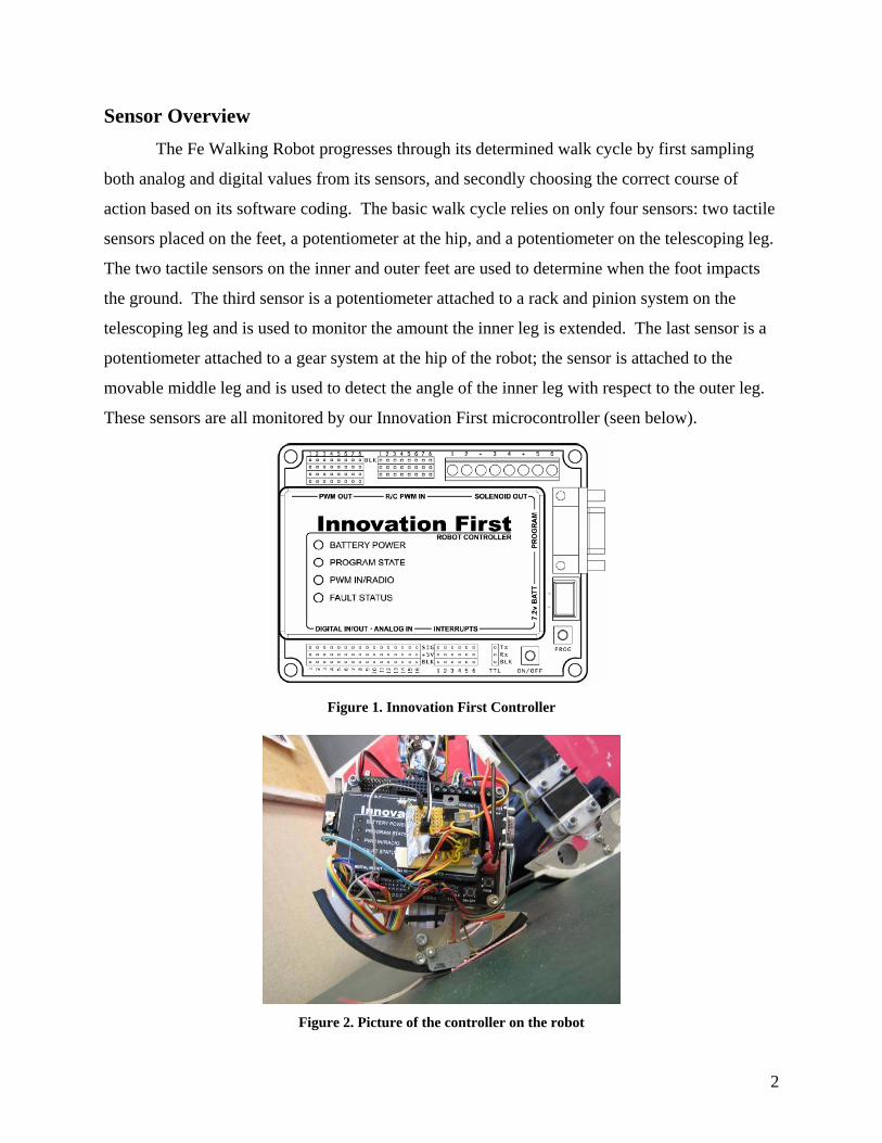
attached to the body. As the potentiometer gear rotates, the potentiometer signal value changes
accordingly. Although the exact values depend on where the gears are initially set, when the leg
is pulled completely back the signal of the potentiometer reads about 2v, and when the leg is
pushed completely forward, the signal of the potentiometer reads about 3v. If the inner leg is
parallel with the outer legs, the signal is about 2.5v. The microcontroller, by reading the hip
potentiometer signal, can determine how far the leg has swung forward with respect to the outer
legs at any given time.
Figure 11. Hip Angle Potentiometer
Leg Position Signal Voltage Microcontroller Value
Pulled Completely Back 2v 409
Parallel 2.5v 512
Pushed Completely Forward 3v 614 Figure 12. Hip Angle Potentiometer Output Table

7
Figure 13. Placement of Potentiometer
Leg Length Potentiometer
The leg potentiometer knob has also been attached to a gear and is fixed on the non-
telescoping part of the inner leg. On the telescoping part of the leg is a gear rack. As the
telescoping part of the leg moves up and down, the pinion gear attached to the potentiometer
spins, changing the value of the potentiometer signal. When the leg is fully retracted, the
potentiometer signal reads +0v and when the leg is fully extended, the potentiometer signal reads
+5v.
Leg Position Signal Voltage Microcontroller Value
Completely Retracted 0v 0
Extended 50% 2.5v 512
Completely Extended 5v 1023 Figure 14. Leg Length Potentiometer Output Table

8
Figure 15. Leg Length Potentiometer Figure 16. Placement of Sensor

9
Additions to the Robot Sensors and a microcontroller aren’t the only things that can help a robot walk.
Additional devices such as solenoids, launch aids, and indicator LEDs make the robot walk
farther and more reliably. Without these things, progress that has taken us weeks might have
taken months or even years to accomplish.
Solenoids and Solenoid Driver
Solenoids
A solenoid is a solid magnetic metal rod that sits inside a hollow metal cylinder. The
metal rod moves freely and can slide in and out of the cylinder when no voltage is applied to the
two leads of the solenoid. However, when a voltage (approximately 12v) is applied across the
two leads, the metal rod is magnetically pushed out of the cylinder. This force action makes a
solenoid a convenient device for pushing something for a short period of time. For our robot, the
solenoid is used to unlock the hip-locking mechanism (which is described in greater detail in the
mechanical team report). The problem with a solenoid is that the microcontroller has only low-
current +5v digital outputs available (80 milliamp current maximum). Because of the force
requirements, we needed to select solenoids which requires a +12v signal and draws several
hundred milliamps of current.
Figure 17. Two solenoids mounted on the robot

10
Solenoid Driver
The solenoid driver consists of 2 inputs - a low current +5v digital signal and a high
current +12v power supply - and one output. When the digital signal input is “high” (or +5v),
the output of the driver is connected to the +12v power supply. This turns on the solenoid. In
this state, the driver only requires 150 microamps of current from the digital signal. When the
digital signal input is “low” (or +0v), the output of the driver is connected to ground. In this
state, the solenoid receives no power and remains off. Hence, the solenoid can be controlled
with a low current digital signal from the microcontroller.
Solenoid Action Input Voltage Input Current Output Voltage Output Current
Off +0v 0 A +0v 0 A
On +5v 150 uA +12v 200 mA Figure 18. Solenoid Driver Input/Output Table
This driver uses a special chip package called the 32R418 package. The inputs are
connected to the appropriate pins and the output is connected to the output pin. No other special
wiring is necessary. Because there are two solenoids, we have two of these chips:
Figure 19. Actual Solenoid Driver Board

11
Figure 20. Schematic for Solenoid Driver
Laser Line-Up
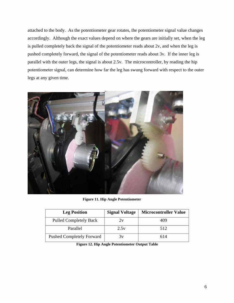
Based off our new launch technique, it was imperative that we launch the robot from the
same angle each time. To aid in this, lasers were mounted along the two outer legs of the robot.
When turned on, the lasers shine two red dots on the floor. As long as the middle leg is at the
same length and position for launch, the red dots will line up to a specific spot on the floor for a
consistent launch. In this case, two rulers are used to allow for adjustability of launch angles
while enabling repeatability. See the mechanical team paper for more in depth detail about this.
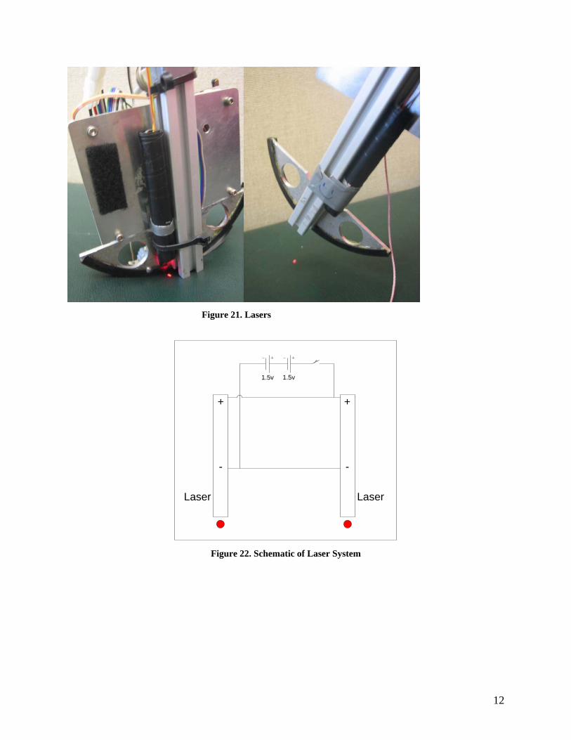
Because turning on two lasers at the same time while also trying to launch the robot
proved to be difficult, a master laser on/off switch was created. The AA-batteries were removed
from the laser cases, and were wired in series with a single limit switch. The ON buttons of the
lasers were then permanently pressed. When the limit switch is not pressed, neither laser
receives battery power because of the open circuit. However, when the limit switch is pressed,
the batteries are connected to the battery terminals of the lasers, and the lasers both turn on. This
allows for a single switch, placed on top of the robot, to control both lasers on the bottom of the
robot.
12
Figure 21. Lasers
+
-
Laser
+
-
Laser
1.5v1.5v
Figure 22. Schematic of Laser System
13
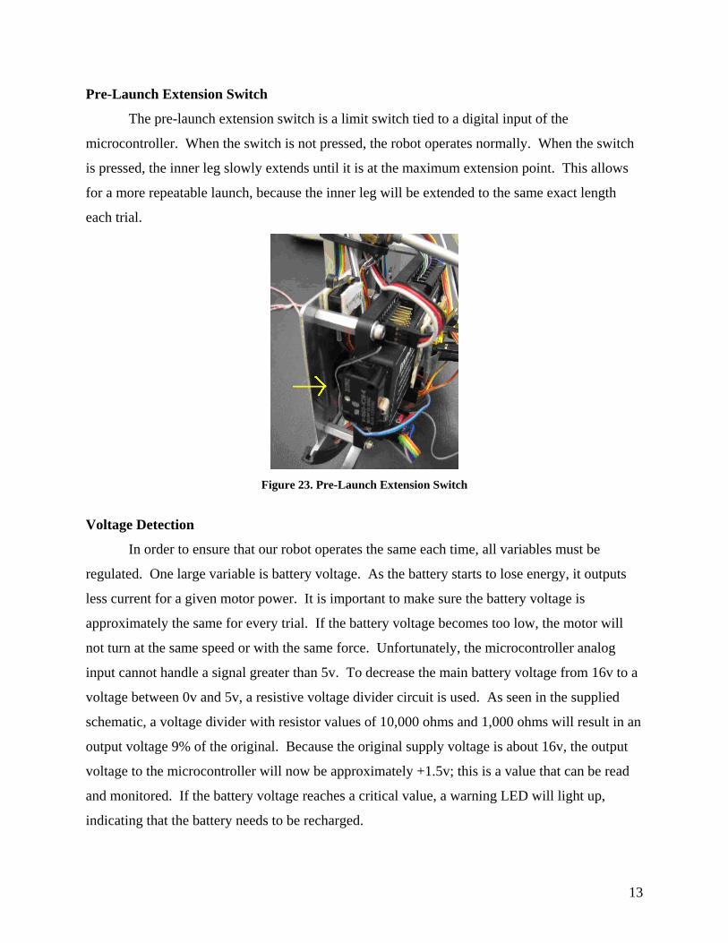
Pre-Launch Extension Switch
The pre-launch extension switch is a limit switch tied to a digital input of the
microcontroller. When the switch is not pressed, the robot operates normally. When the switch
is pressed, the inner leg slowly extends until it is at the maximum extension point. This allows
for a more repeatable launch, because the inner leg will be extended to the same exact length
each trial.
Figure 23. Pre-Launch Extension Switch
Voltage Detection
In order to ensure that our robot operates the same each time, all variables must be
regulated. One large variable is battery voltage. As the battery starts to lose energy, it outputs
less current for a given motor power. It is important to make sure the battery voltage is
approximately the same for every trial. If the battery voltage becomes too low, the motor will
not turn at the same speed or with the same force. Unfortunately, the microcontroller analog
input cannot handle a signal greater than 5v. To decrease the main battery voltage from 16v to a
voltage between 0v and 5v, a resistive voltage divider circuit is used. As seen in the supplied
schematic, a voltage divider with resistor values of 10,000 ohms and 1,000 ohms will result in an
output voltage 9% of the original. Because the original supply voltage is about 16v, the output
voltage to the microcontroller will now be approximately +1.5v; this is a value that can be read
and monitored. If the battery voltage reaches a critical value, a warning LED will light up,
indicating that the battery needs to be recharged.

14
Figure 24. Voltage Divider
Relative Hip Positioning
Because of the nature of the hip potentiometer, the swing range of full back to full
forward will span a different voltage range depending on how the gears are initially lined up. To
compensate for this, every time the microcontroller is booted up, it is necessary to calibrate the
hip sensor. To do this, pull the leg all the way to the full back position and press the “Calibrate”
button. This action will record the full back position voltage, and all reported voltages will be
the signal voltage minus the full back voltage. Consequently, full back will be read as +0v and
full forward will always be read as approximately +2v, regardless of the actual absolute voltages
being read by the potentiometer.
Example # Absolute Voltage
Range
Recorded Voltage at
Full Back
Relative Voltage
Range
1 .5v to 2.5v .5v 0v to 2v
2 1.5v to 3.5v 1.5v 0v to 2v
3 2.5v to 4.5v 2.5v 0v to 2v Figure 25. Hip Positioning Input/Output Table
A similar calibration is not needed on the leg length potentiometer because its full range
of motion is already from the maximum of +0v to +5v; there is never a variable range.

15
LED Indicators
To help with the video analysis of our walk cycle, 4 “ultra bright” LEDs have been
mounted on the side of our robot. They are each connected in series with a resistor and are
attached to the solenoid outputs of the microcontroller. The solenoid outputs can be turned on or
off in the code. Two LEDs represent when the inner and outer leg sensors are triggered and the
other two LEDs indicate when the front and back solenoids are firing. These 4 events were
selected to be represented by the LEDs because it is difficult to see exactly when each event
occurs when watching a video replay of the robot walking. Overall, the LEDs were useful
indicators to finding and debugging locking mechanism and walk cycle problems.
LED input 1
LED input 2
LED input 3
LED input 4
Figure 26. Picture of LEDs Figure 27. LED Schematic

16
Microcontroller Code Overview A microcontroller is only as powerful and as useful as the code within it. Our
microcontroller takes given inputs and converts this knowledge into useful electrical outputs. In
addition, the controller can be also used to display debugging information when it is connected
directly to a computer.
STATE MACHINE While walking, the robot transitions through four step cycles. The 4 cycles are named the
following: Outer Swing, Push Off, Middle Swing, and Extension. The robot walking cycle was
covered in the previous report, but here is a brief reminder of how it transitions from each stage
to the next. Our current launch technique starts the robot in Outer Swing. Once the legs swing
through and lands, the outer leg touches the ground and triggers the Outer Impact limit switch.
The state transitions to Push Off and the middle leg extends to the longest length; immediately
after, it retracts to the shortest length. When in Push Off, if the Leg Length (discussed later)
becomes shorter than a certain value (called Leg Short), then the state becomes Middle Swing.
The shortened middle leg swings through and it impacts the ground triggering the Middle Impact
limit switch the state transitions to extension. The middle leg then extends to middle length and
once it reaches a certain length (Leg Medium) the state becomes Outer Swing and the cycle
repeats over again. All of this code is contained in function "void
Process_Data_From_Local_IO(void)" in file "user_routines_fast.c".
SENSOR INPUT
Analogue
Five analog input variables are used: LegLength, HipAbsolute, LegMedium,
PrelaunchLength, and Battery. They are Inputs 1,2,3,4, and 8 in the code, respectively.
// Step 1: Get Analog Input Values LegLength = Get_Analog_Value(Pot1_Signal); HipAbsolute = Get_Analog_Value(Pot2_Signal); LegMedium = Get_Analog_Value(Pot3_Signal); PrelaunchLength = Get_Analog_Value(Pot4_Signal); Battery = Get_Analog_Value(Pot8_Signal);

17
The inputs were definded as Pot#_Signal for ease of use. In user_routines.c, in the fuction void
User_Initialization (void), these inputs are declared as analog inputs. Then function
Process_Data_From_Local_IO in user_routines_fast.c calls the fuction Get_Analog_Value,
which converts the analog signal to an integer value between 0 to 1023, and stores it in one of the
input variables named above.
The LegLength value is used to determine the exact length of the middle leg. When it is
shortest it has a value of 0, and when longest it is 1023.
HipAbsolue is used for calibration of the hip angle. When the calibration limit switch is
pressed, it stores the current value of HipAbsolute in a variable called HipAdjust. The switch
should be pressed when the middle leg is as far back as possible. Then the HipAdjust value will
be subtracted from HipAbsolute, giving the HipAngle which we can use for later operations.
This makes HipAngle range from 0 to about 300, instead of a similar range that does not start at
0.
LegMedium is the value which the leg extends to during the Extension state. It is
adjusted via a potentiometer located above the microcontroller. It takes on a value from 0 to
1023.
PreLaunchLength is used in conjunction with a limit switch to slowly extend the length
of the middle leg to the desired length, equal to PrelaunchLength. LegLength is checked against
PreLaunchLength and when they are equal the leg stops extending.
Battery uses a voltage divider and takes a value from 0 to 214. It is based on the current
voltage of the battery, and decreases from 214 for a full charge as the battery is used.
Digital
For the digital inputs we use the interrupts to allow more room for digital outputs. It is
not required to initialize them in user_routines.c since they are already initialized as inputs. We
currently use four digital inputs: PreLaunchSwitch, CalibSwitch, MiddleImpact, and
OuterImpact, which are on the interrupts 1,2,5 and 6 respectively (this is defined in
user_routines.h).
When pressed, the PreLaunchSwitch slowly extends the leg to PreLaunchLength
(determined by a potentiometer). It also sets the state to OuterSwing, which is the state we
launch from. This also resets the step count, which will be discussed later.

18
CalibSwitch is used to calibrate the hip angle (Step 2 of Process_Data_From_Local_IO).
When pressed it subtracts a value from the HipAbsolute to give us a consistent HipAngle
(discussed earlier)
MiddleImpact is pressed during the walk cycle and gives the controller feedback as to
when the middle leg is in contact with the ground. We currently use it to move from one state to
the next, from MiddleSwing to Extension.
OuterImpact is similar to MiddleImpact but for the outer legs (it is currently on the right
leg, but this does not matter because they contact at the same time). At outer leg impact, the
state changes from OuterSwing to Pushoff.
OUTPUTS
PWM
The motor speed is controlled by void MotorOutput(void) called in void
Process_Data_From_Local_IO(void) of user_routines_fast.c. It uses the state to adjust the motor
variable. This variable is then used in the next line of code that outputs this variable to the PWM
function and spins the motor. The motor begins turning at a value of around 127, and we use a
maximum speed of 240 in our code.
If the robot is in PushOff and the leglength is less than the LegShort value, then the
function calls RampUp(240) which gradually increases the value of Motor by IncrementUp until
it reaches 240. When in Extension, if the LegLength is less then LegMedium we use
RampUp(240) as well.
When in MiddleSwing or OuterSwing the fuction RampDown() is called which decreases
Motor until it reaches 127 (note: we have stored the value 127 in Off in user_routines.h for ease
of use).
LED
We are currently using ultra-bright LEDs which draw more current than a digital output
would allow for, so we are required to use the solenoid outputs. This is not a problem since the
current solenoids are partially controlled by an external circuit and do not require the use of the
solenoid outputs. In step 3 of Process_Data_From_Local_IO in user_routines_fast.c the LEDs

19
are turned on and off. They are controlled like a digital output (have a value of 1 or 0). Four
LEDs are currently used. They are lit when the front or back solenoid triggers, and when each of
the impact sensors are hit. The output from the solenoid-out is sent to an external circuit where
the LEDs are wired in series with a resistor as described earlier.
Solenoid
Solenoids are used to lock and unlock the “locking mechanism” on the robot to stop the
legs from swinging back in once they have swung out. They use an external circuit as described
earlier in the paper. SolFront is the front solenoid, digital output 15, and SolBack is the back
solenoid, digital output 16. They are controlled in step 5 of Process_Data_From_Local_IO, in
user_routines_fast.h, which calls the function void SolOutput(void). If the state is currently
Extension or OuterSwing when the middle impact limit switch is closed, the front solenoids
extend for 490 cycles. When the state is MiddleSwing or PushOff and the outer impact switch is
closed, the rear solenoid extends for 490 cycles.
DATA
The only way we get feedback from the robot is through the terminal window in the
IOLoader. We use the printf fuction to display any desired text in this window. Currently we
are displaying the number of cycles in-between each step, and the number of steps it takes. This
is performed in StepFuction in user_routines_fast.c which is called whenever the robot is in
MiddleSwing or OuterSwing state and the appropriate impact sensor is closed. The number of
steps is reset when the PreLaunch limit switch is pressed.

20
Launch Overview One major problem discovered during robot testing was the inconsistency of our original
launching method. Every launch was different and starting parameters varied, which in turn
undermined the reproducibility of our test results. To solve this problem, we focused mainly to
control the most important launch variable: the launch position, which includes the middle leg
length, locking angle, and forward/backward launch angle. Several solutions implemented
(gradually) - designing and lego-constructing a mechanical “launch pad”, utilizing the locking
mechanism and launching from a set locked position, mounting laser pointers alongside the leg
to indicate launch angle position, and changing the code to incorporate a launch switch which
when pressed would automatically reset the robot to the same “pre-launch” state every time – all
had various degrees of success. The lego launcher was generally unreliable and took too long to
set up, so it was replaced with a laser pointer attached to one of the outer legs, which reduced
launch setup time from five to ten minutes to one minute. Later, another laser pointer was
attached to the other leg to control horizontal tilt. In the end, the most successful launch
technique used the locking mechanism, the double lasers line-up, and the pre-launch extension
switch, which together, controlled most of the variability in the starting launch position (the two
laser pointers’ alignment however do not distinguish between horizontal tilt and rotational tilt,
but it is easy to correct for rotational tilt).
Descriptions of the laser line-up and the pre-launch extension switch are included in this
report. In-depth information about launch techniques is described in the mechanical team report.

21
Difficulties Encountered with Electrical Systems In all, we had one unexpected major equipment failure, and several other minor but still
troublesome problems. Each problem varied in cost, consequence, and solution. As more
problems appeared and some old ones resurfaced, we had to revise our problem solving
methodology for these sudden setbacks.
Before:
Step one: find the problem
Step two: patch the problem (easiest and quickest solution) so that we can continue
Now:
Step one: identify the problem – “What is the problem? What is wrong?”
Step two: locate source of problem and understand problem – “Where is the problem? What is
causing the problem? Why does the problem exist?”. Consult expert help if necessary.
Step three: consider possible solutions of problem, weigh each solution’s pro and con.
Step four: implement solution chosen (which may still be easiest and quickest solution)

22
Problems Encountered Throughout the Semester: Problem Title: Switch Durability Motor Reliability Bad Connections to Battery
Problem Description:
1. Limit switch becomes detached from feet 2. Lever on limit switch breaks Gearhead of our motor breaks. Battery had bad connection to microcontroller
Frequency: 1. extremely often, up to several times a week 2. 3-5 times in total A few times in total About once a week
Cause: 1. Adhesive for attachment of limit switch to feet not strong enough 2. Switch may be of lesser quality and durability
- lack of dampening system for feet impact during walking cycle; shock is transferred from impact to the motor.
Battery clips, because of wear and tear, became too loose for a secure connection
Consequences
1. Time is wasted (~15 minutes) trying to reattach the limit switch to the feet. Previous limit switch placement on feet becomes lost so some consistency for testing are lost. 2. Testing halts until limit switch is replaced, which takes ~1 hour but wait time for fix may be a few days.
- no testing can occur without a motor and if no backup motor exists, time lost = time it took for new motor to arrive
- Power loss to both the battery and the microcontroller
Attempted Solutions:
1. used double sided tape (lasts a few days) -> hot glue (lasts around a week) -> drilled holes in feet, mounted limit switch and used screws to attach feet 2. replaced broken limit switch with new one
- purchased higher quality, more reliable motor (but not used) - Impact disrupting systems
Reshape battery clips and hot glue wires in place
Results:
1. Limit switches are now attached to feet permanently with screws, but now switch is no longer adjustable 2. Replaced limit switch works as before. Should look for options
- motor has not broken since changes have been made
Permanently solder battery to robot but add a switch to allow robot to be turned off or charged

23
Problems Encountered Throughout the Semester Continued:
Problem Title: Recharge Batteries Impact Disrupting Systems Losing a Microcontroller
Problem Description: After use, batteries are not recharged so they remain at low voltage
Harsh impacts and related problems caused by lack of a damping system.
Innovation First microcontroller stopped working
Frequency: actual frequency: unknown; estimate at least several testing sessions a month Several times a testing period once
Cause: - difficult to tell if batteries need to be recharged - easy to forget
- lack of dampening system for feet impact during walking cycle
- lack of shock absorber transferred shock from feet impact into damaging the microcontroller
Consequences
- low voltage batteries mean motor turns at lower rpm and with less force. - inconsistent battery voltage causes inconsistency in the walking cycle which makes undermines the reliable of our test results
- possible reason for why microcontroller stopped working - possible reason for why limit switches fall off feet - possible reason for why limit switches break - possible reason for wires coming off
- No testing can occur without a microcontroller. Time lost = time it took for new microcontroller to arrive = ~1 week
Attempted Solutions:
- informed testers of problem - designed and implemented voltage detection circuit: LED will light up if battery voltage is too low
- dampening on feet of robot with foam - flexible cam
- fix microcontroller (not possible) - order new microcontroller - analyze cause of problem and implement solutions so that problem does not occur again
Results: - testers will no longer be unaware if battery voltage is too low Impact related problems occur less frequently - new microcontroller has not broken since
changes have been made

24
The Future With all of our progress this last year, even bigger problems have arisen, which require
even more complicated solutions. Sometimes a complete overhaul of a system is the easiest and
best solution. Some large scale electrical fixes are the implementation of a new motor with new
motor control, and the use of a completely new microcontroller.
New Motor
A high quality motor was purchased from MicroMo for two reasons. One is the new
motor can be fitted with an optical encoder. An optical encoder
compri
ses of a rotating disk (code disk), a light source (LED photoemitters), and a photodetector. The
light source is positioned on one side to the inner edge of the disk, and the photodetector is
positioned on the other side. The rotating disk’s edge has patterns which let light through and
blocks light. As the disk rotates and the pattern switches from letting light through to blocking
light, the photodetector would detect the light signal on and off, and generate a digital output.
The quadrature encoder has two output channels 90 degrees out of phase; by observing the
number of pulses on one output and the phase difference between the two outputs, one can
determine both the position and direction of the motor (with respect to some reference point),
which would allow for precise position and speed control of the motor in the code. The second

25
season we bought a new motor is because it is superior to the current motor in quality, reliability,
durability, performance, and power – everything except size and price. Combined with the
planetary gearhead, the motor has an output speed of 450 rpm and stall torque of 3.9 Nm, which
is more than twice the speed and power the current motor provides. Additionally, we do not
have to worry about the gearhead breaking from feet impact with the new motor, since the
gearhead has all steel gears which can handle 4.5 Nm continuous and 6 Nm intermittent torque.
The reason the new motor has not been mounted on the robot is due to its problematic
size. The motor together with the gearhead and the optical encoder is over 4 inches, and after
exploring various mounting options and designs, the mechanical team concluded that mounting
the new motor on our current robot is difficult, impractical and perhaps even unnecessary. This
topic is described in greater detail in the mechanical team report.
Isopod
The Isopod is a small microcontroller with all the capabilities of the Innovation First
microcontroller plus two quadrature decoders suitable for the new motor’s optical decoder. The
Isopod is superior performance and capability wise to the Innovation First microcontroller in that
it has a 40 Mhz master clock – 40 MIPs (million instructions per cycle) – as opposed to the
Innovation First’s 10 MIPs. On the downside, the isopod is more complicated and less user
friendly. For example, the Isopods smaller size and design precludes an “on” button or a built-in
serial port. Additionally, there is only one ground pin for the general purpose input and output
pins, so an additional board would have to be used to connect existing connector pieces (from the
robot) to the isopod. With the Isopod, only the necessary components for functionality are
included. Unlike the Innovation First microcontroller, space usage on the Isopod has been
minimized such that no extra components (for convenience) exist.
The Isopod can be programmed in either C or a virtually parallel language called IsoMax,
which simulates state machines. We decided to program the Isopod in C since we are more

26
familiar with it and our original robot code is in C. Porting the program over from the
Innovation First microcontroller to the Isopod microcontroller proved to be more difficult than
expected, as the Isopod is very different from the Innovation First microcontroller. As of now,
only digital inputs and inputs, and analog inputs have been set up correctly to work.

27
Report Acknowledgements: The Electrical Team would like to thank Andy Ruina and Jason Cortell for their
continued support throughout the year. They provided new ideas for electrical projects and they
helped us to think through our problems and arrive at the best solutions possible. We would also
like to thank Ellie Weyer for her leadership of the Fe Team, Chris Cheng and the rest of the Fe
Mechanical Team, and JP Ren and the Fe Business Team. Without them, we would not have a
robot to wire up. Lastly, we would like to thank ECE students Adrian Wong and Kevin Graf for
their technical suggestions on part choices and techniques to solve some of our hardest electrical
problems.