FDM Management Module - CA...
42
FDM Management Module SPECTRUM Enterprise Manager Device Management Supports Management Module SM-CSI1012 Titlepage Titlepage Titlepage Titlepage
-
Upload
trinhtuong -
Category
Documents
-
view
218 -
download
0
Transcript of FDM Management Module - CA...

FDM Management Module
SPECTRUM Enterprise ManagerDevice Management
Supports Management Module SM-CSI1012
TitlepageTitlepageTitlepageTitlepage

S P E C T R U M E n t e r p r i s e M a n a g e r Page 2 F D M M a n a g e m e n t M o d u l e
NoticeAprisma Management Technologies, Inc. (Aprisma), reserves the right to makechanges in specifications and other information contained in this document withoutprior notice. The reader should in all cases consult Aprisma to determine whetherany such changes have been made.
The hardware, firmware, or software described in this manual is subject to changewithout notice.
IN NO EVENT SHALL APRISMA, ITS EMPLOYEES, OFFICERS, DIRECTORS,AGENTS, OR AFFILIATES BE LIABLE FOR ANY INCIDENTAL, INDIRECT,SPECIAL, OR CONSEQUENTIAL DAMAGES WHATSOEVER (INCLUDING BUTNOT LIMITED TO LOST PROFITS) ARISING OUT OF OR RELATED TO THISMANUAL OR THE INFORMATION CONTAINED IN IT, EVEN IF APRISMA HASBEEN ADVISED OF, KNOWN, OR SHOULD HAVE KNOWN, THE POSSIBILITYOF SUCH DAMAGES.
Copyright © November, 2000 by Aprisma Management Technologies. All rightsreserved.
Printed in the United States of America.
Order Number: 9030829-01
Aprisma Management Technologies, Inc.121 Technology DriveDurham NH 03824
SPECTRUM, the SPECTRUM IMT/VNM logo, DCM, IMT, and VNM are registeredtrademarks, and SpectroGRAPH , SpectroSERVER , Inductive ModelingTechnology , Device Communications Manager , and Virtual Network Machineare trademarks of Aprisma or its affiliates.
Ethernet is a trademark of Xerox Corporation.
Virus DisclaimerAprisma makes no representations or warranties to the effect that the LicensedSoftware is virus-free.
Aprisma has tested its software with current virus checking technologies. However,because no anti-virus system is 100% reliable, we strongly caution you to writeprotect and then verify that the Licensed Software, prior to installing it, is virus-freewith an anti-virus system in which you have confidence.
Restricted Rights Notice(Applicable to licenses to the United States Government only.)
1. Use, duplication, or disclosure by the Government is subject to restrictions asset forth in subparagraph (c) (1) (ii) of the Rights in Technical Data andComputer Software clause at DFARS 252.227-7013.
Aprisma Management Technologies, Inc.121 Technology DriveDurham NH 03824
2. (a) This computer software is submitted with restricted rights. It may not beused, reproduced, or disclosed by the Government except as provided inparagraph (b) of this Notice or as otherwise expressly stated in the contract.
(b) This computer software may be:
(1) Used or copied for use in or with the computer or computers for whichit was acquired, including use at any Government installation to whichsuch computer or computers may be transferred;
(2) Used or copied for use in a backup computer if any computer for whichit was acquired is inoperative;
(3) Reproduced for archival or backup purposes;
(4) Modified, adapted, or combined with other computer software, providedthat the modified, combined, or adapted portions of the derivativesoftware incorporating restricted computer software are made subjectto the same restricted rights;
(5) Disclosed to and reproduced for use by support service contractors inaccordance with subparagraphs (b) (1) through (4) of this clause,provided the Government makes such disclosure or reproductionsubject to these restricted rights; and
(6) Used or copied for use in or transferred to a replacement computer.
(c) Notwithstanding the foregoing, if this computer software is publishedcopyrighted computer software, it is licensed to the Government, withoutdisclosure prohibitions, with the minimum rights set forth in paragraph (b) ofthis clause.
(d) Any other rights or limitations regarding the use, duplication, or disclosureof this computer software are to be expressly stated in, or incorporated in,the contract.
(e) This Notice shall be marked on any reproduction of this computer software, inwhole or in part.

D e v i c e M a n a g e m e n t Page 3 F D M M a n a g e m e n t M o d u l e
ContentsINTRODUCTION 4
FDDI Modules for the MMAC-FNB..................................4FDM Management Information Bases.........................6Proper Modeling of the FDM .......................................6FDM Applications ........................................................6SPMA and the FDM.....................................................7
MODELING THE FDM 9
Single Ethernet to FDDI LAN ..........................................9Multiple Ethernet LANs to an FDDI LAN.......................12
DEVICE TOPOLOGY VIEWS 14
FDM DevTop View ....................................................14Off-Page Reference Panel .....................................14Simplified Device View Panel ................................15Device Icon Panel ..................................................15Port Connections Panel .........................................17Bridging Interface Icons .........................................17
Concentrator DevTop View .......................................20FDDI Port Icons .....................................................20
DEVICE VIEWS 23
Chassis Device View ....................................................23Logical Module Icons.................................................25
Module Number/Notes Facility ...............................27
Module Type/Concentrator Device Configuration ViewLabel ...............................................................27
Interface Type/GenBridgePort Notes Facility ............28Port Number/FDDI Port Notes Facility ......................28Port Type...................................................................28Port Status/Port Configuration View Label ................29Bridge Interface Status/Bridge Port Configuration View
Label...................................................................29Physical Device View....................................................30
Icon Subviews Menu Selections................................32
CONFIGURATION VIEWS 33
FDM Device Configuration View ...................................33FDM Device Configuration View Fields.....................33
Interface Configuration Table ................................34Interface Device Detail View .....................................35
Concentrator Device Configuration View ......................35Station Configuration.................................................35SMT Information........................................................38
MODEL INFORMATION VIEW 39
INDEX 40

D e v i c e M a n a g e m e n t Page 4 F D M M a n a g e m e n t M o d u l e
Introduction
This section describes the SPECTRUM Management Module for the FDM.
This section also provides the model type names assigned to the hubs in SPECTRUM. The model type name refers to the template used to specify attributes, actions, and associations for device models in SPECTRUM.
FDDI Modules for the MMAC-FNBAprisma Management Technologies FDDI modules for the MMAC-FNB FDDI modules are:
FDMMIM (FDDI Management Media Interface Mod-ule)The FDMMIM is an Ethernet to FDDI bridge providing the connection between the Ethernet “A” channel on the MMAC and the FDDI portion of the FNB. The FDMMIM provides SMT/SNMP management of other FDDI modules (FDCMIM-04 and FDCMIM-08) in the same MMAC chassis.
FDMMIM-04 (FDDI Management Media InterfaceModule)The FDMMIM is an Ethernet to FDDI bridge and a four port concentrator on a single module. The FDMMIM-04 provides all the functionality of the FDMMIM with four additional master (“M”) ports for connecting to other FDDI devices.
Note:Note:
If you are running a previous version of SPECTRUM, the following user interface aspects may differ from those in SPECTRUM version 4.0:-Order and names of menu selections-Navigational features (mouse button functionality)For information about menu selections and navigating within previous versions of SPECTRUM, refer to the SPECTRUM Views documentation.

D e v i c e M a n a g e m e n t Page 5 F D M M a n a g e m e n t M o d u l e
FCDMIM-04
FDCMIM-08 (FDDI Concentrator Media InterfaceModules)The FDCMIM-04 and FDCMIM-08 provide four and eight concentrator “M” ports respectively. These modules provide additional FDDI connections when inserted to the left of and adjacent to the FDM module in the MMAC-FNB chassis. The FDC modules provide no
management functions. The FDC modules communicate with an FDM through the FNB. Although the FDC modules can work independently of the FDM, the FDM is required to provide a connection to the FDDI dual counter-rotating ring and to provide management functions. Bridging Ethernet to FDDI with the FDMFigure 1 shows a representation of an Ethernet to FDDI bridge.
Figure 1: Bridging Ethernet to FDDI with the FDM
MMAC-FNB FDM FDC
MMAC-FNBEthernet Bus
MMAC-FNBFDDI BusFDDI Ring
ConnectionsA B
EthernetNetwork

D e v i c e M a n a g e m e n t Page 6 F D M M a n a g e m e n t M o d u l e
FDM Management InformationBasesSpectrum management of an FDM is based on the following Management Information Bases (MIBs) which come as a part of the software module fo the model type:
• Internet MIB-II (RFC 1213)• FDDI MIB (RFC 1285)• IETF Bridge MIB (RFC 1286)• CTSMTMIB - Cabletron Systems Enterprise-
Specific MIB• Cabletron Systems Common-MIB (not fully
implemented)• Backplane Protocol MIB
Proper Modeling of the FDMYou can create the FDM model to represent the physical FDM device bridging between two networks. Figure 2 shows a representative modeling of the FDM in SPECTRUM. The Section, Modeling the FDM, explains the proper process.
Figure 2:Figure 2:Figure 2:Figure 2: Bridging Ethernet to FDDI with the FDM in SPECTRUM
FDM ApplicationsThe FDM supports only common applications. Common applications are described int he MIB II Applications, Bridging Applications, and Miscellaneous Application, and are as follows:
• Gen Bridge App (Gen_Bridge_App)
BdgCSIFDMMMAC-FNB MMAC-FNB
Ethernet network(LAN_802_3 model)
FDM Ethernet toFDDI bridge model
FDDI network(FDDI model)
FDDI hub applicationmodel (HubSCIFDDI)MMAC-FNB with
installed FDM and related modules

D e v i c e M a n a g e m e n t Page 7 F D M M a n a g e m e n t M o d u l e
- Spanning Tree (Span_Tree_App)- Static (Static_App)- Transparent (CT_Tp_App)
• MIB-II (SNMP2_Agent)- ICMP (ICMP_App)- IP (IP2_App)- System (System2_App)- UDP (UDP2_App)
• DownLoad App (CtDownLoadApp)• FDDI SMT (FddiSMT)
SPMA and the FDMSPECTRUM also provides SPECTRUM Portable Management Application (SPMA) functionality for the FDM. To open the SPMA Application view from any SPECTRUM view, follow these steps:
1 Select Icon Subviews from the View menu; or, highlight the FDM model and click the middle mouse button to access the Icon Subviews menu.
2 Select Utilities from the Icon Subviews menu.
3 Select SPMA from the Utilities menu.
The SPMA Application view provides buttons to select SPMA-specific views and dialog boxes. provides an example of an SPMA Application view.
The SPECTRUM Portable Management Application Tools Guide provides additional information on the following SPMA tools:
• Using the MIB-I, MIB-II Tool, Chapter 2, explains how to use this tool to view and change MIB-1 and MIB-II object ID values.
• Using the Community Names Tool, Chapter 3, explains Cabletron’s component structure of device MIBs, and describes how to change device community names.
132.177.118.24 of type BRtrCSIuMMACT
Applications
Community Names
Download App of type CtDownLoadApp
TFTP Download
Close
Trap TableHub View
Alarm Configuration
Network 1 of typeTRHubStack
StatisticsRing Security
MIB-II of type SNMP2_Agent
Generic SNMP (MIB I
Bridging of type CSIBridge
Bridge View
132.177.118.24 of type FddiSMT
FDDI Alarm Config
Port ConfigurationSMT/MAC Config
Connection Policy

D e v i c e M a n a g e m e n t Page 8 F D M M a n a g e m e n t M o d u l e
• Using TFTP Download Tool, Chapter 5, explains how to upgrade firmware on Cabletron devices equipped with Flash EEPROMs.
• Using the SNMP Traps Tool, Chapter 6, explains how to establish which network management workstations on your network will receive trap alarms from a selected device, and also provides a brief overview of some of the traps supported by Cabletron Systems’ devices.

D e v i c e M a n a g e m e n t Page 9 F D M M a n a g e m e n t M o d u l e
Modeling the FDM
Tthis section describes the procedures for modeling the FDM Ethernet to FDDI bridging module in SPECTRUM
SPECTRUM requires that certain modeling conventions be followed in order for it to correctly monitor and manage physical devices or applications. If you use AutoDiscovery to create your FDM models, it will locate the devices on your network and create the associated models, but will not impose the proper configuration automatically. Follow the instructions contained in this section to impose the proper configuration upon models that AutoDiscovery has already created.
If you create models of your FDM devices manually, follow the modeling procedures explained in this section to create a model that is consistent with the conventions and rules used by the AutoDiscovery program when it constructs a network model, and impose the proper configuration upon that model.
Single Ethernet to FDDI LAN
To model a single Ethernet LAN to an FDDI LAN in SPECTRUM, follow this procedure:
1 Create a LAN_802_3 conceptual model.
2 Create an FDDI conceptual model.
3 Create a BdgCSIFDM model.
Note:Note:
In order to follow the steps in this section you must have a working knowledge of icon creation, cutting, copying, pasting, and the Device Topology (DevTop) view. For more information on using the DevTop view, refer to the SPECTRUM Views documentation.

D e v i c e M a n a g e m e n t Page 10 F D M M a n a g e m e n t M o d u l e
4 Navigate into the LAN_802_3 and create an MMAC-FNB model representing the hub in which the FDM is installed.
5 Navigate into the Device Topology (DevTop) view of the MMAC-FNB model and copy the BdgCSIFDM icon to the appropriate port on the Port Connections Panel.
6 Navigate into the DevTop view of the BdgCSIFDM model, copy the HubCSIFDDI hub icon from the Port Connections Panel, and paste it into the FDDI model.
7 In the BdgCSIFDM DevTop view, move the MMAC-FNB model’s Off-Page Reference to the appropriate port in the Port Connections Panel.
8 SPECTRUM creates the Off-Page Reference and pipe connections automatically (refer to Figure 3).
This completes the procedure for modeling a single Ethernet to FDDI LAN. Figure 3 illustrates
modeling a single Ethernet to FDDI LAN with the FDM.
Caution:Caution:
Do NOT use CUT and paste to move the HubCSIFDDI icon onto the FDDI model. Use COPY and paste.

D e v i c e M a n a g e m e n t Page 11 F D M M a n a g e m e n t M o d u l e
Figure 3: Modeling a Single Ethernet to FDDI LAN
FDM modelbridgingEthernet andFDDI LANs.
MMAC-FNBwith installedFDM.
Copy the Concentrator modelfrom the FDM DeviceTopology View, and paste itinto the FDDI network model.
LAN_802_3
FDDI
Concentrator
BdgCSIFDM
MMAC-FNB
D e v i c e M a n a g e m e n t Page 12 F D M M a n a g e m e n t M o d u l e
Multiple Ethernet LANs to anFDDI LANTo model multiple Ethernet LANs to an FDDI LAN in SPECTRUM, follow this procedure:
1 Create a LAN_802_3 conceptual model to represent each of the Ethernet networks.
2 Create an FDDI conceptual model.
3 Create each BdgCSIFDM model.
4 Navigate into each LAN_802_3 and create an MMAC-FNB model representing each hub in which an FDM is installed.
5 Navigate into the Device Topology (DevTop) view of each MMAC-FNB model and copy the respective BdgCSIFDM icon to the appropriate port on the Port Connections Panel.
6 Navigate into the DevTop view of each BdgCSIFDM model, copy each HubCSIFDDI hub icon from the Port Connections Panel, and paste each into the FDDI model.
7 In each BdgCSIFDM DevTop view, move the MMAC-FNB model’s Off-Page Reference to the appropriate port in the Port Connections Panel.
8 SPECTRUM creates the Off-Page References and pipe connections automatically (refer to Figure 4).
This completes the procedure for modeling multiple Ethernet LANs to an FDDI LAN. Figure 4 illustrates modeling multiple Ethernet LANs to an FDDI LAN with the FDM.
Caution:Caution:
Do NOT use CUT and paste to move the HubCSIFDDI icons onto the FDDI model. Use COPY and paste.

D e v i c e M a n a g e m e n t Page 13 F D M M a n a g e m e n t M o d u l e
Figure 4: Modeling Multiple Ethernet LANs to an FDDI LAN
Two FDMmodelsbridging twoEthernetLANs to oneFDDI LAN.
1. Copy each HubCSIFDDI model from each FDM DevTop view.
2. Paste each copy into the FDDI network model.
3. Draw a logical pipe connection between the HubCSIFDDI models and the FDM Off-Page References within the FDDI LAN.
FDDI
LAN_802_3
LAN_802_3
HubCSIFDDI
HubCSIFDDI
BdgCSIFDM
BdgCSIFDM
Configuration inside FDDI LAN
HubCSIFDDI DevTop View
4. Open the DevTop View for each HubCSIFDDI model within the FDDI LAN.
5. Move the HubCSIFDDI model’s Off-PageReference icon onto a port connection in eachHubCSIFDDI DevTop view.

D e v i c e M a n a g e m e n t Page 14 F D M M a n a g e m e n t M o d u l e
Device Topology Views
This section describes the device in terms of its ports and port connections.
The FDM Management Module supports two Device Topology views:
• FDM Device Topology View• Concentrator Device Topology View
FDM DevTop ViewAccess: From the FDM icon, select DevTop from the IconSubviews menu.
The FDM DevTop View allows you to logically connect other devices to the Ethernet or FDDI bridging interfaces on the FDM and view statistics on the FDM’s connection to the FDDI network. The FDM model type software also “connects” a concentrator icon to the FDM’s FDDI bridging interface, and places it in the FDM DevTop View. Figure 5 provides an example of an FDM DevTop View.
Off-Page Reference PanelThe Off-Page Reference Panel, in the top left section of the FDM DevTop view, displays icons representing network devices connected to the FDM. These triangular-shaped icons must be logically connected to a port in the Port Connections Panel for SPECTRUM to correctly monitor and manage the connected device. To logically connect an Off-Page Reference icon to an FDM port, follow these steps:
1 Select EditEditEditEdit from the File menu.
2 Click on the Off-Page Reference icon.
3 Drag the Off-Page Reference icon onto a port in the Port Connections Panel at the bottom of the DevTop view (the triangular-shaped device icon changes to a rectangular icon).
4 Select Save & CloseSave & CloseSave & CloseSave & Close from the File menu.

D e v i c e M a n a g e m e n t Page 15 F D M M a n a g e m e n t M o d u l e
Simplified Device View PanelThe Simplified Device View Panel, in the top center of the FDM DevTop view, contains a picture of the MMAC-FNB chassis with an installed FDM. Clicking on an image of a module installed in the chassis allows the selected module’s port information to be gathered in the DevTop view’s Port Connections Panel.
Device Icon PanelThe Device Icon Panel, in the top right section of the FDM DevTop View, displays the Location View Icon for the FDM. This icon provides the same double-click functions and visual status presentations as the FDM Location View Icon.

D e v i c e M a n a g e m e n t Page 16 F D M M a n a g e m e n t M o d u l e
Figure 5: FDM DevTop View
Primary Landscape 0x00400000 - VNM Host - FDM of type BdgC-
BdgCSIFDM
FD
FDC M44
00
FddiSMT
FDDIFWD
1ENETFWD
2
Off-Page Reference icons for the FDM. These icons need to be connected to a port.
Simplified Device view. FDM selected.
FDM Location view Icon. Use this icon to navigate to subviews for the FDM.
Icon for automaticallycreated concentratormodel.
Status, activity and information for the FDM’s FDDI and Ethernet bridging interfaces. Use these interface icons to access the Bridge Port subviews.
iFileÿ View HelpTools Bookmarks
SpectroGRAPH: Device Topology

D e v i c e M a n a g e m e n t Page 17 F D M M a n a g e m e n t M o d u l e
Port Connections PanelThe Port Connections Panel, located at the bottom of the FDM DevTop view, represents the ports contained in the FDM. You can move device models that appear in the Off-Page Reference Panel to the Port Connections Panel and connect them to the appropriate FDM port. You can also create new device models with the New Model option from the Edit menu, and connect them to the proper FDM port.
The device-to-port connection process is controlled by the “Connects_to” relation rules. SPECTRUM checks these rules to verify that the connection can be made. Once you make a connection between a device and an FDM, an association forms between the port and the connected device with this “Connects_to” relation. SPECTRUM also forms a “Collects” relation between the newly connected device model, its connected port, and the FDM.
The FDM model type software automatically “connects” a concentrator icon to the FDDI port and places it in the FDM DevTop view. You must then copy the concentrator model from the DevTop view and paste it into the FDDI network model to allow the FDM to gather statistics on the configuration and performance of the FDDI network. For more information on the proper
modeling procedure, refer to the modeling instructions for your particular network configuration earlier in this section.
Bridging Interface IconsBridging interface icons representing the Ethernet and FDDI ports on the FDM appear at the bottom of the Port Connections Panel. Figure 6 provides a detailed illustration of the bridging interface icons. You can access the Icon Subviews menu by clicking the middle mouse button where indicated, or highlighting the icon and selecting Icon SubviewsIcon SubviewsIcon SubviewsIcon Subviews from the View menu.

D e v i c e M a n a g e m e n t Page 18 F D M M a n a g e m e n t M o d u l e
Figure 6: FDM Bridging Interface Icon
Port NumberThis label displays the number identifying the interface.
Interface TypeThis label displays the type of hardware interface for the port. Possible interface types are: FDDI or ENET (Ethernet).
Interface Status/Port Configuration View LabelThis label displays the status of the FDM’s bridging interfaces. Table 1 provides status
definitions. Double-clicking on the label accesses the Port Configuration view.
FDDI
FWD
1
Multi-Attribute Line Graph/PortPerformance View Label
Interface Status/Port Configuration View Label
Interface TypePort Number
Close WindowNavigateModel AlarmsPerformanceNotes...UtilitiesDetailSub-InterfacesIF StatusIF ConfigurationAddress Translation Table-Secondary Address PanelThresholdsModel Information

D e v i c e M a n a g e m e n t Page 19 F D M M a n a g e m e n t M o d u l e
Multi-Attribute Line Graph/Port Performance ViewThis area of the interface provides a Multi-Attribute Line Graph, indicating bridge port activity. Table 2 provides color definitions for statistics appearing in this graph. For more information on Multi-Attribute Line Graphs, and how to use them, refer to the manual How to Manage Your Network in SPECTRUM. Double-clicking on this graph accesses the Port Performance view.
Table 1: Interface Status Definitions
Interface Status Definition
DIS (Disabled) Management has disabled the interface. No traffic can be received or forwarded while the interface is disabled.
BLK (Blocking) The interface will not forward any traffic.
LST (Listening) The FDM is not adding information to the Filtering Database but is monitoring BPDU traffic while preparing to move from the Learning to the Forwarding state.
LRN (Learning) The FDM is learning network addresses. The Learning state occurs when the FDM’s Acquired Database is being created during start-up or reconfiguration.
FWD (Forwarding) The FDM is on-line and this interface is forwarding traffic.
Table 2: Multi-Attribute Line Graph Color Definitions
Color Definition
Yellow Receive Rate
Gray % Filtered
Blue % Forwarded
Orange Transmitted Rate

D e v i c e M a n a g e m e n t Page 20 F D M M a n a g e m e n t M o d u l e
Concentrator DevTop ViewAccess: Navigate into the FDM Devtop view, then accessConcentrator DevTop view through the concentrator icon.
The Concentrator DevTop view allows you to logically connect other devices to ports on modules installed in the MMAC-FNB chassis, and gather statistics on those port connections. The Off-Page Reference, Simplified Device View, and Port Connections Panels have the same functionality, and provide the same information, as those described in the FDM DevTop view earlier in this section. The Device Icon Panel displays the concentrator icon instead of the FDM
icon, and provides access to subviews for the concentrator. Figure 8 on Page 22 provides an example of a Concentrator DevTop view.
FDDI Port IconsPort icons representing the FDM or FDC module’s FDDI ports appear in the Port Connections Panel. Figure 7 provides a detailed illustration of the FDDI port icons. You can access the Icon Subviews menu by clicking the middle mouse button where indicated, or highlighting the icon and selecting Icon SubviewsIcon SubviewsIcon SubviewsIcon Subviews from the View menu.
Figure 7: FDDI Port Icon
Port NotesDouble-clicking on this area of the icon accesses the FDDI port notes facility.
Port Number/Port Configuration ViewThis label displays the number identifying this port. Double-clicking on the label accesses the Port Configuration view.
Port Type
Port Status
Port Number/Port Configuration View Label
Port Notes
Port 2
B-Type
Notes
Active
CloseNavigateAlarmsPerformanceNotes...UtilitiesConfiguration
D e v i c e M a n a g e m e n t Page 21 F D M M a n a g e m e n t M o d u l e
Port StatusThis area of the icon displays the status of the port.
Port TypeThis area of the icon displays the FDDI port type. Table 3 defines the possible FDDI port types.
Table 3: Possible FDDI Port Types
Port Type Description
A-Type Connects to the incoming primary ring and outgoing secondary ring. This port is a part of a dual attachment station (DAS) or dual attachment concentrator (DAC).
B-type Connects to the outgoing primary ring and incoming secondary ring. This port is a part of a DAS or DAC and is also used to connect a DAS to a DAC.
M-Type Connects a concentrator to a single attachment station (SAS), DAC, or another concentrator (DAC or single attachment concentrator [SAC]). This port is only implemented in a DAC or SAC.
S-Type Connects a SAS or SAC to a concentrator (DAC or SAC).

D e v i c e M a n a g e m e n t Page 22 F D M M a n a g e m e n t M o d u l e
Figure 8: Concentrator DevTop View
Primary Landscape 0x00400000 - VNM Host - of type
FD
FDC M44
00
BdgCSIFDM
FddiSMT
Port 1.0
RptrPort
NotesPort 1
A-Type
Notes
ActivePort 2
B-Type
Notes
Active
Simplified Device View. FDM selected.
Concentrator Location View icon. Use this icon to navigate to subviews for the concentrator.
Icon representing that the FDM is attached to this concentrator port.
Status and information for the FDDI interfaces. Use the Type-A and Type-B interface icons to access the Port Configuration view, and the RptrPort interface icon to access the HubCSIFDDI Performance view.
iFileÿ View HelpTools Bookmarks
SpectroGRAPH: Concentrator Device Topology

D e v i c e M a n a g e m e n t Page 23 F D M M a n a g e m e n t M o d u l e
Device Views
This section provides a description of the Device views for the FDM management module.
The Device views allow you to view either a physical or a chassis (logical) representation of the FDM bridging and FDC concentrator modules installed in the MMAC-FNB chassis. The Device views also provide you with menu bar access to the views that monitor and control the FDM and FDC modules and ports.
• The Chassis Device View allows you to view the logical representations of the modules. From this view, you can access performance, configuration, and status information about the modules and ports.
• The Physical Device View displays a physical representation of the modules installed in the MMAC-FNB chassis.
These Device views show the FDM’s configuration. When the port or application status is modified, the display reflects those changes after the model’s next polling cycle. When a module is added or removed from the chassis, SPECTRUM
displays those changes when a model reconfiguration occurs.
Chassis Device ViewAccess: From the FDM icon, select Device > Chassis fromthe Icon Subviews menu.
The Chassis Device view gives a logical representation of the modules in the chassis, and the current configuration. If the configuration changes, you see the corresponding change within this view. This change in the view occurs after the model’s next polling cycle, which is determined by the time interval assigned to the Configuration Timer. Figure 9 shows an example of an FDM Chassis Device view.

D e v i c e M a n a g e m e n t Page 24 F D M M a n a g e m e n t M o d u l e
Figure 9: FDM Chassis Device View
Primary Landscape 0x00400000 - VNM Host - FDM of type BdgCSIFDM
Model Name
Contact
Description
Location
Network Address
Primary Application
System Up Time
Manufacturer
Device Type
Serial Number
3
34 M
5 M
6 M
FDM00
FWDFDDI
FWDENET
Gen Bridge App
ACT
ACT
2
FDC44
CON
CON
CON
CON
M
21 A
B
Fileÿ View HelpTools Bookmarks
i
SpectroGRAPH: Device
D e v i c e M a n a g e m e n t Page 25 F D M M a n a g e m e n t M o d u l e
Logical Module Icons
The Chassis Device view displays a logical representation of each of the FDDI modules installed in the MMAC-FNB. Each port on the FDM or FDC module is represented. You can access additional views for the module or port by -clicking on the module or port to highlight it and selecting Icon SubviewsIcon SubviewsIcon SubviewsIcon Subviews from the View menu, or double-clicking on the various icon zones. Figure 10 provides a detailed illustration of the Logical Module Icon and the following sections detail each icon zone. You can access the menus displayed by clicking and holding the middle mouse button where indicated.

D e v i c e M a n a g e m e n t Page 26 F D M M a n a g e m e n t M o d u l e
Figure 10: Logical Module Icon Detail
FDM00
FWDFDDI
FWDENET
ACT
ACT
2
21 A
B
Module Number/Notes Facility
Module Type/
Port Number/FDDI Port Notes Facility
Port Status/
Bridge Interface Status/
Close WindowNavigateModel AlarmsUtilitiesNotesEventsPort Configuration
Port Type
Close WindowNavigateModel AlarmsUtilitiesNotesEventsModule NotesDevice Configuration ViewCsTelScript
Close WindowNavigateModel AlarmsUtilitiesNotesEventsPort NotesEnable/Disable PortPort Configuration View
Concentrator DeviceConfiguration View Label
Interface Type/GenBridgePort Notes Facility
Port Configuration View Label
Bridge Port Configuration View Label

D e v i c e M a n a g e m e n t Page 27 F D M M a n a g e m e n t M o d u l e
Module Number/Notes FacilityThis label displays the MMAC slot number in which the module resides. Double-clicking on the label accesses the FDM notes facility. Table 4 outlines the menu selections available per module, excluding the generic options Navigate, Utilities, Notes, Events, and Alarms.
Module Type/Concentrator DeviceConfiguration View LabelThis label displays the FDM or FDC module type. Table 5 provides a brief description of the available module types. Double-clicking on this label accesses the Concentrator Device Configuration view.
Table 4: Module Menu Selections
Menu Selection Description
Module Notes Opens the Module Notes facility.
Device Configuration view
Opens the FDM Device Configuration view.
CsTelScript Allows you to telnet to the ESXMIM.
Table 5: Module Type Description
Module Type Description
FDM00 An FDM Ethernet to FDDI bridging module providing SMT/SNMP management of other FDDI modules (FDC04 and FDC08).
FDM04 An FDM Ethernet to FDDI bridging module with four additional “M” concentrator ports for connecting to other FDDI devices.
FDM24 An FDM FDDI Dual Attached Concentrator (DAC) that supports unshielded twisted pair (UTP) cable. This module provides the same bridging and management functions as the FDM04 while also providing FDDI connectivity for up to four workstations over UTP cable.

D e v i c e M a n a g e m e n t Page 28 F D M M a n a g e m e n t M o d u l e
Interface Type/GenBridgePortNotes FacilityThis label displays the interface type for the FDM’s bridging interfaces. Interface types are either FDDI or Ethernet (ENET). Double-clicking on the label accesses the GenBridgePort notes facility.
Port Number/FDDI Port NotesFacilityThis label displays the number identifying the port. Double-clicking on the label accesses the FDDI Port notes facility.
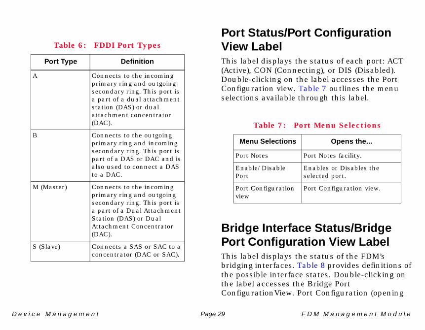
Port TypeDisplays the FDDI port type. Table 6 shows the possible FDDI port types.
FDM30 An FDM FDDI Dual Attached Station (DAS) that supports single mode fiber. This module provides the same bridging and management functions as the FDM04.
FDC04 A four “M” multimode concentrator port module managed by the FDM.
FDC08 An eight “M” multimode concentrator port module managed by the FDM.
FDC24 A four “M” UTP concentrator port module managed by the FDM.
FDC28 An eight “M” UTP concentrator port module managed by the FDM.
FDC34 A four “M” single mode fiber concentrator port module managed by the FDM.
FDC38 An eight “M” single mode fiber concentrator port module managed by the FDM.
FDC44 A four “M” STP concentrator port module managed by the FDM.
FDC48 An eight “M” STP concentrator port module managed by the FDM.
Table 5: Module Type Description
Module Type Description
D e v i c e M a n a g e m e n t Page 29 F D M M a n a g e m e n t M o d u l e
Port Status/Port ConfigurationView LabelThis label displays the status of each port: ACT (Active), CON (Connecting), or DIS (Disabled). Double-clicking on the label accesses the Port Configuration view. Table 7 outlines the menu selections available through this label.
Bridge Interface Status/BridgePort Configuration View LabelThis label displays the status of the FDM’s bridging interfaces. Table 8 provides definitions of the possible interface states. Double-clicking on the label accesses the Bridge Port ConfigurationView. Port Configuration (opening
Table 6: FDDI Port Types
Port Type Definition
A Connects to the incoming primary ring and outgoing secondary ring. This port is a part of a dual attachment station (DAS) or dual attachment concentrator (DAC).
B Connects to the outgoing primary ring and incoming secondary ring. This port is part of a DAS or DAC and is also used to connect a DAS to a DAC.
M (Master) Connects to the incoming primary ring and outgoing secondary ring. This port is a part of a Dual Attachment Station (DAS) or Dual Attachment Concentrator (DAC).
S (Slave) Connects a SAS or SAC to a concentrator (DAC or SAC).
Table 7: Port Menu Selections
Menu Selections Opens the...
Port Notes Port Notes facility.
Enable/Disable Port
Enables or Disables the selected port.
Port Configuration view
Port Configuration view.

D e v i c e M a n a g e m e n t Page 30 F D M M a n a g e m e n t M o d u l e
the Port Configuration view) is the only menu selection available through this label.
Physical Device ViewAccess: From the FDM icon, select Device > Physicalfrom the Icon Subviews menu.
This section describes the module information available from the FDM Physical Device view, which displays a physical representation of the FDM and FDC modules installed in an MMAC-FNB chassis. Figure 11 provides an example of a Physical Device view.
Table 8: Possible Port States and Definitions
State Definition
DIS Disabled – Management has disabled the port. No traffic can be received or forwarded while the port is disabled.
LRN Learning – The FDM is learning network addresses. The Learning state occurs when the FDM’s Acquired Database is being created during startup or reconfiguration.
LST Listening – The FDM is not adding information to the Filtering Database but is monitoring BPDU traffic while preparing to move from the Learning to the Forwarding state.
FWD Forwarding – The FDM is on-line and this port is forwarding traffic.
BLK Blocking – The port will not forward any traffic.
BRK Broken – The port is malfunctioning.

D e v i c e M a n a g e m e n t Page 31 F D M M a n a g e m e n t M o d u l e
Figure 11: Physical Device View
Primary Landscape 0x00400000 - VNM Host - FDM of type BdgC-
Model Name
Contact
Description
Location
Network Address
Primary Application
System Up Time
Manufacturer
Device Type
Serial NumberGen Bridge App
FDCMIM-44SN
FNB
FDMMIMSN
PWR
FD FD
1
2
3
4
PST
PST
PST
PST
LNK
LNK
LNK
LNK CONSOLE
MODEM
RES
PWRTWPXMTRCVWRPROP
STBYSYOKXMTRCVCLNPOK
LNK
ENFD
BYPASS
FDDI
–
B
FDDI
–
A
iFileÿ View HelpTools Bookmarks
SpectroGRAPH: Device

D e v i c e M a n a g e m e n t Page 32 F D M M a n a g e m e n t M o d u l e
Icon Subviews Menu SelectionsTable 9 outlines the menu selections available per module.
Table 9: Physical Device View - Module Icon Subviews Menu Selections
Menu Selection Opens the...
Module Notes Module Notes view.
Device Configuration view
FDM Device Configuration view.

D e v i c e M a n a g e m e n t Page 33 F D M M a n a g e m e n t M o d u l e
Configuration Views
This section provides descriptions of the configuration views that are available or the FDM and concentratormodel to access and modify network configuration information.
The FDM and concentrator models support the following configuration views:
• FDM Device Configuration View• Concentrator Device Configuration View
FDM Device ConfigurationViewAccess: From the FDM icon, select Configuration fromthe Icon Subviews menu.
The FDM Device Configuration view provides information on the configuration and operating status of the FDM’s interfaces.
FDM Device Configuration ViewFieldsThe FDM Device Configuration View provides the following fields and buttons:
Contact StatusThe contact status of the device.
This button opens the DownLoad Application view. This view allows you to upgrade the firmware for a device from a TFTP Boot or Bootp Server. For more information on this view, refer to the SPECTRUM Portable Management Application Tools Guide.
This button opens the Trap Table view. This view allows you to enable and disable SNMP traps on the device. For more information on this view, refer to the SPECTRUM Portable Management Application Tools Guide.
TFTP Download
Trap Table

C o n f i g u r a t i o n V i e w s
D e v i c e M a n a g e m e n t Page 34 F D M M a n a g e m e n t M o d u l e
This button opens the Community Table view. This view allows you to change the community names for all MIB components on the device. For more information on this view, refer to the SPECTRUM Portable Management Application Tools Guide.
This button opens the FDM Interface Detail view, described later in this section.
Interface Configuration TableThe Interface Configuration Table provides the following port configuration information for each of the FDM’s bridging interfaces:
This button updates all the information in the table.
This button switches the Interface Address entries between the MAC and Canonical addresses.
This button allows you to apply a specific filter to a column entry.
This button allows you to arrange the display of information by a defined parameter.
Interface AddressThe Ethernet (MAC) address of the port.
DescriptionA textual description of the interface including the name of the manufacturer and the product name.
Community Table
Interface Detail
Update
MAC/Canonical
Set/Clear Filter
Sort Up/Down

C o n f i g u r a t i o n V i e w s C o n c e n t r a t o r D e v i c e C o n f i g u r a t i o n V i e w
D e v i c e M a n a g e m e n t Page 35 F D M M a n a g e m e n t M o d u l e
TypeThe type of hardware interface for the port. Possible interface types are: fddi or ethernet-csmacd .
Oper StatusThe State of the port (Up, Down, or Testing ).
Admin StatusThe desired operational state of the port (Up, Down, or Testing ) selectable through the File/UpdateFile/UpdateFile/UpdateFile/Update feature.
Interface Device Detail ViewThe Interface Device Detail View provides the following detailed configuration information for the selected FDM bridging interface:
Interface IndexThe interface index displays the number identifying the current interface.
Inbound ErrorsThe number of inbound error packets that have occurred.
Inbound DiscardsThe number of inbound packets that have been discarded.
Inbound Non UnicastThe number of inbound broadcast packets.
Outbound ErrorsThe number of outbound error packets that have occurred.
Outbound DiscardsThe number of outbound packets that have been discarded.
Outbound Non UnicastThe number of outbound broadcast packets.
Concentrator DeviceConfiguration ViewAccess: From the concentrator icon, select Configurationfrom the Icon Subviews menu.
The Concentrator Device Configuration view provides information on the configuration and operating status of the concentrator.
Station ConfigurationThe Station Configuration section provides the following information:

C o n f i g u r a t i o n V i e w s
D e v i c e M a n a g e m e n t Page 36 F D M M a n a g e m e n t M o d u l e
Ring StateThe current state of the FDDI Ring. Table 10 shows the possible states.
MAC ConfigurationThe actual configuration of the concentrator. Table 11 shows the possible configurations.
MAC PathThe ring that this concentrator resides on: Primary , Secondary , or Local .
MAC AddressThe MAC address of this concentrator.
MAC CountThe number of MACs supported by this concentrator.
Non Master PortsThe number of Non Master ports on this concentrator.
Master PortsThe number of Master ports on this concentrator.
Table 10: FDDI Ring State Description
Ring State Description
Isolated The concentrator is not attached to the ring.
Non-Op The concentrator is attempting to enter the ring.
Ring-Op The ring is operational.
Detect The claim/beacon process of the FDDI ring protocol has exceeded 1 second. This indicates a potential problem.
Non-Op-Dup The ring failed to complete the claim/beacon process because a duplicate FDDI address has been detected.
Ring-Op-Dup The ring is operational but a duplicate FDDI address has been detected.

C o n f i g u r a t i o n V i e w s
D e v i c e M a n a g e m e n t Page 37 F D M M a n a g e m e n t M o d u l e
Directed The claim/beacon process did not complete within 9 seconds. The concentrator is now sending directed beacons to indicate a problem.
Trace A problem has been detected with the station or its upstream neighbor. A trace is being sent to notify the upstream neighbor of the problem. The concentrator and all stations between the concentrator and its upstream neighbor will run self-tests.
Table 11: Ring Connection Descriptions
Configuration Description
Isolated Both PHY-A and PHY-B are disconnected from the ring. There are no connections at either the A or B FDDI port.
Wrap-A PHY-A is wrapped via the MAC (from PHY-A/Primary In to MAC to Secondary Out/PHY-A) and PHY-B is disconnected.
Table 10: FDDI Ring State Description (Continued)
Ring State Description
Wrap-B PHY-B is wrapped via the MAC (from PHY-B/Secondary In to MAC to Primary Out/PHY-B) and PHY-A is disconnected.
Wrap-AB PHY-B is connected to the MAC (from PHY-B/Secondary In to MAC to Primary Out/PHY-B) and PHY-A is wrapped (connecting Primary In to Secondary Out), isolating PHY-A from the MAC.
Through-A Indicates that the primary ring is connected to the MAC (from PHY-A/Primary In to MAC to Primary Out/PHY-B). The secondary ring is isolated from the MAC (from PHY-B/Secondary In to PHY-A/Secondary Out).
Through-B Indicates that the secondary ring is connected to the MAC (from PHY-B/Secondary In to MAC to Secondary Out/PHY-A). The primary ring is isolated from the MAC (from PHY-A/Primary In to PHY-B/Primary Out).
Table 11: Ring Connection Descriptions (Continued)
Configuration Description
C o n f i g u r a t i o n V i e w s
D e v i c e M a n a g e m e n t Page 38 F D M M a n a g e m e n t M o d u l e
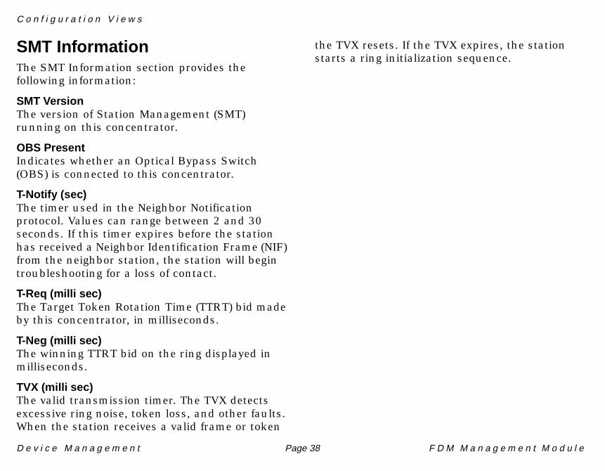
SMT InformationThe SMT Information section provides the following information:
SMT VersionThe version of Station Management (SMT) running on this concentrator.
OBS PresentIndicates whether an Optical Bypass Switch (OBS) is connected to this concentrator.
T-Notify (sec)The timer used in the Neighbor Notification protocol. Values can range between 2 and 30 seconds. If this timer expires before the station has received a Neighbor Identification Frame (NIF) from the neighbor station, the station will begin troubleshooting for a loss of contact.
T-Req (milli sec)The Target Token Rotation Time (TTRT) bid made by this concentrator, in milliseconds.
T-Neg (milli sec)The winning TTRT bid on the ring displayed in milliseconds.
TVX (milli sec)The valid transmission timer. The TVX detects excessive ring noise, token loss, and other faults. When the station receives a valid frame or token
the TVX resets. If the TVX expires, the station starts a ring initialization sequence.

D e v i c e M a n a g e m e n t Page 39 F D M M a n a g e m e n t M o d u l e
Model Information View
This section provides a brief description of the Model Information views available for models of FDM devices inSPECTRUM.
Model Information views provide descriptive and configuration information about SPECTRUM models of individual devices, interfaces, and applications. Figure 12 shows an example of the Model Information view accessed from the Icon Subviews menu for the MicroMMAC-E model’s Device icon. Model Information views are also available for each of the Interface icons in the Interface Device and Interface Device Topology views, and for each of the Application icons in the Application view. Although these views may vary slightly depending on the particular entity being modeled, their basic layout and content are similar for most SPECTRUM management modules. Therefore these views are described in more detail in the SPECTRUM Views documentation.
Figure 12:Figure 12:Figure 12:Figure 12: Model Information View
freesia of type BRtrCSIuMMAC of Landscape: Primary
Primary Application
System Up Time
Manufacturer
Device Type
Serial Number
Network AddressNameContactDescriptionLocation
File View HelpTools
MM Version Number
MM Name
MM Part Number
General Information
Model Created By
Model Type
Model Creation Time
Model State
Security String
Communication Information
Community Name
DCM TimeOut
DCM Retry
Poll/Log InformationPoll Interval
Polling StatusCondition
Condition Value
Contact Status
Lost Child Count
Value When Yellow
Value When Orange
Value When Red
Last Successful Poll
Log Ratio
LOGGED POLLED
MicroMMAC Model Information View
Bookmarks
SpectroGRAPH:132.127.118.24
i

D e v i c e M a n a g e m e n t Page 40 F D M M a n a g e m e n t M o d u l e
42
Index
AAccessing the
Concentrator Device Configuration View 35
Device Topology Views 14Physical Device View 31
Acquired Database 19, 30ACT 29Active 29Admin Status 35Auto-Discovery 9
BBlocking 30BPDU Traffic 19, 30Bridge
Interface Status 29Port Configuration View
Label 29Bridging Interface 14
Icons 17Broken 30
CChassis Device View 23CON 29Concentrator
Device Configuration View 33, 35Label 27
DevTop View 20Conceptual Model 9, 12Configuration Timer 23Connecting 29Contact Status 33
DDAC 21, 29DAS 21, 29Description 34Device
Icon Panel 15, 20Topology Views 14View 23
Chassis 23Physical 30
DIS 29Disabled 29
EENET 28
FFDC 23FDDI 28
Network Model 17Port 37
Icons 20Notes Facility 28
FDM 23Device Configuration View 33
Fields 33DevTop View 14
Filtering Database 19, 30Forwarding 30
GGenBridgePort 28
Notes Facility 28

I n d e x I n d e x
D e v i c e M a n a g e m e n t Page 41 F D M M a n a g e m e n t M o d u l e
HHardware
Interface 18
IIcon Subviews Menu Selections 32Inbound
Discards 35Errors 35Non Unicast 35
InterfaceAddress 34Configuration Table 34Device Detail View 35Index 35Status 18Type 18, 28
LLearning 30Listening 30Logical Module Icons 25
MMAC 37
Address 36Configuration 36Count 36Path 36
Malfunctioning 30Master
Ports 36MMAC-FNB 15Model Information views 39Modeling
A Single Ethernet to FDDI LAN 9Conventions 9Multiple Ethernet LANs to an
FDDI LAN 12Procedure 10, 12
Module 23Number 27Type 27
Multi-Attribute Line Graph 19
NNon Master Ports 36Notes Facility 27
OOBS 38
Present 38Off-Page Reference Panel 14, 20
Oper Status 35Optical Bypass Switch 38Outbound
Discards 35Errors 35Non Unicast 35
PPHY-A 37PHY-B 37Physical Device View 23, 30Polling Cycle 23Port
Activity 19Configuration View 20
Label 18, 29Connections Panel 17, 20Notes 20Number 18, 20, 28Performance View 19Status 21, 29Type 21, 28
Ports 23Primary
In 37Out 37

I n d e x I n d e x
D e v i c e M a n a g e m e n t Page 42 F D M M a n a g e m e n t M o d u l e
RRestricted Rights Notice 2Ring State 36
SSAC 21SAS 21Secondary
In 37Out 37
Simplified Device View Panel 15, 20SMT 27, 38
Information 38Version 38
SNMP 27Station
Configuration 35Management 38
TTarget Token Rotation Time 38T-Neg 38T-Notify 38Trademarks 2T-Req 38TTRT 38TVX 38
Type 35
VViews
Model Information 39