FCS-Module elektronik - Tams Elektronik -...
36
tams elektronik Anleitung | Manual | Mode d´emploi | Handleiding FCS-Module FCS-1 | Art. 54-01016 Einsatzfahrzeug-Belechtung Emergency vehicle light | Feux à éclat Reddingsdienstvoertuigen verlichting FCS-2 | Art. 54-01026 Fahrzeug-Modul | Vehicle module Module pour véhicule | Voertuigmodule FCS-3 | Art. 54-01036 Bus-Modul | Bus module Module pour autobus | Busmodule FCS-4 | Art. 54-01046 Einsatzfahrzeug-Modul | Emergency vehicle module | Module pour véhicule d'intervention Module voor hulpverleningsvoertuigen FCS-L | Art. 54-01096 Beleuchtungsmodul | Lighting module Module d'éclairage | Verlichtingsmodule tams elektronik n n n
Transcript of FCS-Module elektronik - Tams Elektronik -...
tams e
lektro
nikAnleitung | Manual | Mode d´emploi | Handleiding
FCS-ModuleFCS-1 | Art. 54-01016
Einsatzfahrzeug-BelechtungEmergency vehicle light | Feux à éclatReddingsdienstvoertuigen verlichting
FCS-2 | Art. 54-01026Fahrzeug-Modul | Vehicle module
Module pour véhicule | Voertuigmodule
FCS-3 | Art. 54-01036Bus-Modul | Bus module
Module pour autobus | Busmodule
FCS-4 | Art. 54-01046Einsatzfahrzeug-Modul | Emergency vehicle
module | Module pour véhicule d'interventionModule voor hulpverleningsvoertuigen
FCS-L | Art. 54-01096Beleuchtungsmodul | Lighting module
Module d'éclairage | Verlichtingsmodule
tams elektronikn n n

tams e
lektro
nik© 11/2013 Tams Elektronik GmbH
Alle Rechte, insbesondere das Recht derVervielfältigung und Verbreitung sowie derÜbersetzung vorbehalten. Verviel-fältigungen und Reproduktionen injeglicher Form bedürfen der schriftlichenGenehmigung durch die Tams ElektronikGmbH.
Technische Änderungen vorbehalten.
All rights reserved. No part of thispublication may be reproduced ortransmitted in any form or by any means,electronic or mechanical, includingphotocopying, without prior permission inwriting from Tams Elektronik GmbH.
Subject to technical modification.
Tout droits réservés, en particulier lesdroits de reproduction et de diffusion ainsique de traduction. Toute duplication oureproduction sous quelque forme que cesoit nécessite l´accord écrit de la societéTams Elektronik GmbH.
Sous réserve de modifications techniques.
Alle rechten voorbehouden. Niets uit dezepublicatie mag worden vermenig-vuldigdopgeslagen of openbaar gemaakt, zondervoorafgaande schriftelijke toestemmingvan Tams Elektronik GmbH.
Technische wijzigingen voorbehouden.
n
n
n
n
n
n
n
n
n Deutsch 3
n English 32
n Français 61
n Nederlands 90
n
n
tams e
lektro
nik
English FCS modules
Contents
1. Getting started..........................................................................33
2. Safety instructions.....................................................................35
3. Safe and correct soldering.........................................................38
4. Operation overview...................................................................39
4.1. Voltage supply..................................................................394.2. Possible connections .........................................................394.3. Modes of operation............................................................42
5. Technical specifications..............................................................43
6. Special features of the additional components.............................44
7. Mounting..................................................................................47
7.1. Mounting the FCS-1 ..........................................................477.2. Mounting the FCS-2 ..........................................................487.3. Mounting the FCS-3...........................................................507.4. Mounting the FCS-4...........................................................537.5. Mounting the FCS-L ..........................................................56
8. Check list for troubleshooting.....................................................57
9. Guarantee bond........................................................................59
10. EU declaration of conformity......................................................60
11. Declarations conforming to the WEEE directive...........................60
Connection diagramms
FCS-1................................................................................................I
FCS-2..............................................................................................II
FCS-3.............................................................................................III
FCS-4..............................................................................................IV
(Pages I to IV in the centre of this handbook are removeable.)
Page 32

tams e
lektro
nik
FCS modules English
1. Getting started
This manual applies to the following FCS modules compatible to theFaller** Car System, so for:
FCS-1 "Emergency vehicle light" FCS-2 "Vehicle module" FCS-3 "Bus module" FCS-4 "Emergency vehicle module" FCS-L "Lighting module"Provided there are no other details given for particular sections, theinformation given applies to all modules.
How to use this manual
This manual gives step-by-step instructions for safe and correct fitting andconnecting of the module, and operation. Before you start, we advise youto read the whole manual, particularly the chapter on safety instructionsand the checklist for trouble shooting. You will then know where to takecare and how to prevent mistakes which take a lot of effort to correct.
Keep this manual safely so that you can solve problems in the future. Ifyou pass the module on to another person, please pass on the manualwith it.
Intended use
The FCS modules are designed to be operated according to theinstructions in this manual in model building, especially in vehiclescompatible to the Faller** Car-System. Any other use is inappropriateand invalidates any guarantees.
The FCS modules should not be mounted by children under the age of14.
Reading, understanding and following the instructions in this manualare mandatory for the user.
Page 33

tams e
lektro
nik
English FCS modules
Checking the package contents
Please make sure that your package contains:
Module Additional components manual
FCS-1 1 --- 1
FCS-2 1 2111111
resistors 10 Wresistor 10 kWlight sensitive resistordiode 1N4148transistor BC 327reed contactdim switch DS-1
1
FCS-3 1 1111
resistor 10 kWdiode 1N4148transistor BC 327reed contact
1
FCS-4 1 1121
resistor 10 kWdiode 1N4148transistors BC 327loudspeaker
1
FCS-L 1 1 diode 1N4148 1
Required materials
For mounting and connecting you need:
an electronic soldering iron (max. 30 Watt) or a regulated solderingiron with a fine tip and a soldering iron stand;
a tip-cleaning sponge; a heat-resistant mat; a small side cutter, a wire stripper and a pair of tweezers; electronic tin solder (0.5 mm diameter); connecting wire, e.g. enamelled copper wire;
Page 34

tams e
lektro
nik!
FCS modules English
LEDs for the vehicle´s lighting. Depending on the vehicle´s size andconstruction use the following:
SMD LEDs type 0603, 0805 oder 1206 orwired LEDs 1,8 mm;
when connecting white LEDs as front lights to the modules FCS-1,FCS-3 or FCS-4: 2 series resistors with 100 W.
2. Safety instructions
Caution:
Integrated circuits (ICs) are inserted on the module. They aresensitive to static electricity. Do not touch components without firstdischarging yourself. Touching a radiator or other grounded metal partwill discharge you.
Mechanical hazards
Cut wires can have sharp ends and can cause serious injuries. Watchout for sharp edges when you pick up the PCB.
Visibly damaged parts can cause unpredictable danger. Do not usedamaged parts: recycle and replace them with new ones.
Electrical hazards
Touching powered, live components, touching conducting components which are live due to malfunction, short circuits and connecting the circuit to another voltage than
specified, impermissibly high humidity and condensation build upcan cause serious injury due to electrical shock. Take the followingprecautions to prevent this danger:
Never perform wiring on a powered module. Assembling and mounting the kit should only be done in closed,
clean, dry rooms. Beware of humidity.
Page 35

tams e
lektro
nik
English FCS modules
Only use low power for this module as described in this manual andonly use certified transformers.
Connect transformers and soldering irons only in approved mainssockets installed by an authorised electrician.
Observe cable diameter requirements. After condensation build up, allow a minimum of 2 hours for dispersion. Use only original spare parts if you have to repair the kit or the
ready-built module.
Fire risk
Touching flammable material with a hot soldering iron can cause fire, whichcan result in injury or death through burns or suffocation. Connect yoursoldering iron or soldering station only when actually needed. Always keepthe soldering iron away from inflammable materials. Use a suitablesoldering iron stand. Never leave a hot soldering iron or station unattended.
Thermal danger
A hot soldering iron or liquid solder accidentally touching your skin cancause skin burns. As a precaution:
use a heat-resistant mat during soldering, always put the hot soldering iron in the soldering iron stand, point the soldering iron tip carefully when soldering, and remove liquid solder with a thick wet rag or wet sponge from the
soldering tip.
Dangerous environments
A working area that is too small or cramped is unsuitable and can causeaccidents, fires and injury. Prevent this by working in a clean, dry roomwith enough freedom of movement.
Page 36

tams e
lektro
nik!
FCS modules English
Other dangers
Children can cause any of the accidents mentioned above because theyare inattentive and not responsible enough. Children under the age of14 should not be allowed to work with this kit or the ready-builtmodule.
Caution:
Little children can swallow small components with sharp edges, withfatal results! Do not allow components to reach small children.
In schools, training centres, clubs and workshops, assembly must besupervised by qualified personnel.
In industrial institutions, health and safety regulations applying toelectronic work must be adhered to.
Page 37

tams e
lektro
nik!
English FCS modules
3. Safe and correct soldering
Caution:
Incorrect soldering can cause dangers through fires and heat. Avoidthese dangers by reading and following the directions given in thechapter Safety instructions.
Use a small soldering iron with max. 30 Watt. Keep the soldering tipclean so the heat of the soldering iron is applied to the solder pointeffectively.
Only use electronic tin solder with flux. When soldering electronic circuits never use soldering-water or
soldering grease. They contain acids that can corrode componentsand copper tracks.
Solder quickly: holding the iron on the joints longer than necessary candestroy components and can damage copper tracks or soldering eyes.
Apply the soldering tip to the soldering spot in such a way that the wire and the soldering eye are heated at the same time. Simultaneously add solder (not too much). As soon as the solder becomes liquid take it away. Hold the soldering tip at the spot for a few seconds so that the solder flows into the joint, then remove thesoldering iron.
The joint should be held still for about 5 seconds after soldering. To make a good soldering joint you should use a clean and
unoxidised soldering tip. Clean the soldering tip with a damp piece ofcloth, a damp sponge or a piece of silicon cloth.
After soldering check (preferably with a magnifying glass) tracks foraccidental solder bridges and short circuits. This would cause faultyoperation or, in the worst case, permanent damage. You can removeexcess solder by putting a clean soldering tip on the spot. The solderwill become liquid again and flow from the soldering spot to thesoldering tip.
Page 38
tams e
lektro
nik
FCS modules English
4. Operation overview
The modules are particularly designed for the use in vehiclescompatible to the Faller** car system. The modules FCS-1 to FCS-4 areused in vehicles run with two accumulator batteries, the module FCS-Lin vehicles with one accumulator battery or, when reducing the module´sinput voltage, in vehicles run with two accumulator batteries, as well.
4.1. Voltage supply
The accumulator batteries mounted as a standard in the vehicles aresufficient for the voltage supply.
FCS-1 to FCS-4
The voltage of 2,4 V that is provided by the vehicle accumulatorbatteries, is doubled by the module. This enables white and blue LEDsto be connected, which normally need a voltage of more than 2,4 V.
FCS-L
The circuit regulates the input voltage to a constant current of approx.25 mA so that the appropriate voltage for the operation of the LEDs isapplied at the module´s output.
4.2. Possible connections
The modules FCS-1 to FCS-4 have 6 connections each, controlled byspecific software stored in the IC on the PCB. Depending on thespecification of the different versions, LEDs, dim switch, loudspeaker,reed contacts and / or the vehicle´s motor can be connected. It is notnecessary to connect all outputs of the module.
The FCS-L has an output for the connection of red and white LEDs.
Page 39

tams e
lektro
nik
!
English FCS modules
FCS-1 FCS-2 FCS-3 FCS-4 FCS-L
Front lights (white LEDs) + + + + +
Back lights (red LEDs) + + + + +
Brake lights - + + + -
Dim switch DS-1 - + - - -
Flashing lights(blue or orange LEDs)
+ (5) - - + (2) -
Warning lights (yellow LEDs)
- - + - -
Siren (loudspeaker) - - - + -
Motor / acceleration delay - + + + -
Motor / braking delay - + + - -
Front lights
All modules offer the possibiliy to connect white LEDs as front lights.
When connecting white LEDs as front lights to the modules FCS-1, FCS-3 and FCS-4 you have to mount additional series resistors(recommended value: 100 )!
Back lights and brake lights
It is possible to connect red LEDs as back lights to all modules. With theFCS-1 the red LEDs can be connected directly to the vehicle´saccumulator battery, they do not have to be controlled by the module.With the FCS-2 to FCS-4 the red LEDs of back lights are switchedbrighter when stopping. When connecting an additional reed contact tothe FCS-2 or FCS-3 (in order to realise a braking delay) the LED will beswitched brighter during the whole brake application.
Page 40
tams e
lektro
nik
FCS modules English
Dim switch (FCS-2 only)
Depending on the ambient lighting, the lighting of the vehicle isswitched on and off via a light sensitive switch. The sensitivity of theswitch is set via a trimpot.
Flashing lights (FCS-1 and FCS-4)
The FCS-1 has 5 outputs, the FCS-4 two outputs for the connection oforange or blue LEDs as flashing lights.
Warning lights (FCS-3 only)
There are two outputs for the connection in series of LEDS as warninglights on the right and the left side. The function is adapted to the usein (urban) busses. It is not possible to switch the warning lights whenthe vehicle is turning.
Siren (FCS-4 only)
The output for the loudspeaker is switched on and off in short intervalswhile the vehicle is in motion and generates the typical signal.
Motor control / acceleration delay (FCS-2 to FCS-4)
After starting, the motor voltage will be increased gradually, so thevehicles starts gently.
Motor control / braking delay (FCS-2 and FCS-3)
When mounting an additional reed contact into the vehicle it is possibleto realise a braking delay. When crossing the stop with the first reedcontact the motor voltage is reduced and the vehicle brakes. Aftercrossing the stop with the second reed contact the vehicles stops.During the brake application the braking lights are switched brighter.
Page 41
tams e
lektro
nik
English FCS modules
4.3. Modes of operation
FCS-1 "Emergency vehicle light"
According to the connection of the circuit´s input, the LEDs connectedto the five outputs are controlled by two different programmes:
Programme 1 "Double flashlight": The LEDs flash twice each and thengo out for a short time. The LEDs connected to two of the five outputsdouble flash alternately. The other three outputs generate anasynchronous double flash which is interrupted by different intervals.
Programme 2 "Alternating flashlight": Two of the five outputs generatean alternating flash, two others, an alternating double flash. The LEDconnected to the fifth output flashes with a frequency of its own whichis not synchronized to the frequency of the other outputs.
FCS-2 "Vehicle module"
If the vehicle does not receive the signal to drive on for a longer time,all lights connected to the module are switched off (current savingmode).
FCS-3 "Bus module"
When the bus halts more than 10 seconds at a stop, the moduleinterprets the stop as bus stop. The LEDs for the flash light areswitched to "warning light" until the drive on signal, but max. up to oneminute. If the bus does not receive the signal to drive on during oneminute, the flashing lights and the back lights are switched off (currentsaving mode). While starting after a halt at the bus stop the flash lightson the left are switched on for a short time.
At stops where flash lighting is not desired (e.g. at traffic lights orpriority roads), the bus should get the signal to drive on in less than 10seconds. After such a (short) stop the flash lights on the left are notswiched on.
Page 42

tams e
lektro
nik
FCS modules English
FCS-4 "Emergency vehicle module"
While the vehicle is in motion the flashing lights double flash and thesiren is in operation with short breaks. When crossing a stop the backlights are switched brighter for a short time as braking lights and thesiren is switched off (provided the reed contact which is in the vehicle isconnected to the module). As long as the vehicle is in operation theflashing lights are switched on.
5. Technical specifications
FCS-1 to FCS-4
Supply voltage 2 - 3 Volt d.c. voltage
Current consumption(without connected loads) approx. 2 mA
Max. total current 40 mA
Total number of outputsMax. current per outputFCS-4 only: output for loudspeakerImpedanceRated load-carrying capacity
max. 6 (depending on the version)
10 mA1> 32 Ohm> 0.1 Watt
Protected to IP 00
Ambient temperature in use 0 ... +60 °C
Ambient temperature in storage -10 ... +80 °C
Comparative humidity allowed max. 85 %
Dimensions of PCB approx. 12 x 18 x 2.1 mm
Weight of PCB approx. 0.7 g
Page 43
tams e
lektro
nik
English FCS modules
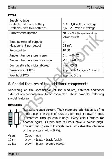
FCS-L
Supply voltage- vehicles with one battery- vehicles with two batteries
0,9 – 1,8 Volt d.c. voltage1,6 – 2,5 Volt d.c. voltage
Current consumption ca. 25 mA (independent of the
voltage applied)
Total number of outputsMax. current per output
125 mA
Protected to IP 00
Ambient temperature in use 0 ... +60 °C
Ambient temperature in storage -10 ... +80 °C
Comparative humidity allowed max. 85 %
Dimensions of PCB approx. 4,2 x 7,4 x 1.7 mm
Weight of PCB approx. 0.1 g
6. Special features of the additional components
Depending on the specification of the modules, different additionalexternal components have to be connected. These have the followingspecial features:
Resistors
Resistors reduce current. Their mounting orientation is of noimportance. The value of resistors for smaller power ratingsis indicated through colour rings. Every colour stands foranother figure. Carbon film resistors have 4 colour rings.The 4th ring (given in brackets here) indicates the toleranceof the resistor (gold = 5 %).
Value Colour rings10 W brown - black - black (gold)10 kW brown - black - orange (gold)
Page 44

tams e
lektro
nik
FCS modules English
Light sensitive resistors
Light sensitive resistors change their value depending on the ambientlighting. As a rule types are used which value decrease with increasinglight intensity. Their mounting orientation is of no importance.
Trimm-potentiometers
Trimm-potentiometers (abrv. "trimm-pots") are resistorswhich allow the value of resistance to be varied and thatway to be adapted to the particular demands. In the middlethey have a small slot into which a small screwdriver can beput in order to vary the value of resistance. The maximumvalue is printed on the housing.
Diodes
Diodes allow the current to pass through in one directiononly (forward direction), simultaneously the voltage isreduced by 0,3 to 0,8 V. Exceeding of the limit voltagealways will destroy the diode, and allow current to flow inthe reverse direction. The diode type is printed on thepackage.
Diodes must be mounted in a given direction. The negative end ismarked with a ring.
Light emitting diodes (LEDs)
When operated in the forward direction the LEDs light. Theyare available in several different versions (differing in colour,size, form, luminosity, maximum current, voltage limits).
The cathode (-) has to be connected to the neagtivevoltage. With wired LEDs the longer wire is the anode (+).With SMD versions the cathode (-) is marked (bevellededge, colour marking or similar).
Light emitting diodes should always be connected via a series resistor
Page 45
tams e
lektro
nik
English FCS modules
which limits the current and prevents failure. With circuits designed forthe connection of LEDs the series resistors are often integrated on thecircuit board.
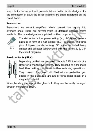
Transistors
Transistors are current amplifiers which convert low signals intostronger ones. There are several types in different package formsavailable. The type designation is printed on the component.
Transistors for a low power rating (e.g. BC types) have apackage in form of a half zylinder (SOT-package). The threepins of bipolar transistors (e.g. BC types) are called basis,emitter and collector (abbreviated with the letters B, E, C inthe circuit diagram).
Reed contacts (SRK)
Depending on their version reed contacts fulfill the task of acloser or a change-over switch. They respond to a magneticfield, thus making possible contactless switching operations.
They consist of a glass bulb filled with a predective gas.Sealed in the glass bulb are two or three reeds made of amagnetic material.
When bending the legs of the glass bulb they can be easily damagedthrough mechanical strain.
Page 46

tams e
lektro
nik!
!
FCS modules English
7. Mounting
7.1. Mounting the FCS-1
Preparation
Open the housing of the vehicle. Locate the position for the module.Follow the connection diagram in the centre of this handbook.
Connection to the supply voltage
Connect the soldering point X1 to the negative pole and the solderingpoint X2 to the positive pole of the accumulator batteries.
Caution: The module should not be connected the wrong wayround. Otherwise it will be damaged when put into operation!
Connection of the LEDs for the flashlights
Connect the anodes (+) of the LEDs to the soldering points X4 to X8and the cathodes (-) to the soldering point X3. Note the differentfunctions of the outputs. Additional series resistors are not necessaryfor the operation of the LEDs for the flashlights.
When you want to run program 2 ("Alternating flashlight") you have tomake a connection between the soldering points X9 and X3. Otherwisethe program 1 ("Double flashlight") is performed.
Connection of the LEDs for the front light
You may connect up to two white LEDs for the front lighting to themodule. Connect the anodes (+) of the LEDs to the soldering point X2and the cathodes (-) to the soldering point X3.
Caution: The LEDs for the front lighting must be operated viaseries resistors (recommended value: 100 ). Otherwise theconnected LEDs are damaged and the circuit may not work asintended.
Page 47

tams e
lektro
nik
!
English FCS modules
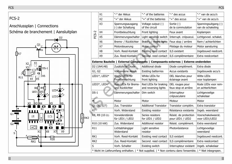
7.2. Mounting the FCS-2
Preparation
Open the housing of the vehicle. Locate the position for the module.Disconnect all connections from the accumulator batteries, the motorand the mounted reed contact except for the wire to the chargingcontact.
Follow the connection diagram in the centre of this handbook and theexplanations to the special features of the additional components(section 6).
In many vehicles the resistor R7 shown in the connection diagram ismounted into the lead-in wire to the motor. The resistor has to beconnected to the plus pole of the accumulator batteries if not yetmounted that way. If there is no resistor, R7 is not applicable.
Connection to the supply voltage
Connect the connecting point X2 to the plus pole of the accumulatorbatteries and the minus pole of the accumulator batteries to theexisting switch S of the vehicle. Connect the second pole of the switchto the connecting point X1.
Caution: The module should not be connected the wrong wayround. Otherwise it will be damaged when put into operation!
Connection of the existing reed contact
The existing reed contact has three connecting points, one at side Aand two at side B. Connect the connecting point at side A to theconnecting point X1 and the existing switch S.
In order to check which one of the two connecting points of side B youhave to connect to the module, connect temporarily the plus pole of themotor to the plus pole of the accumulator batteries and the minus poleof the motor to one of the two connecting points at side B of the reedcontact. If the motor does not run with this connection, you have to
Page 48

tams e
lektro
nik!
FCS modules English
connect this connecting point to the plus pole of the motor and theother connecting point of the reed contact, together with the enclosedresistor R10 (10 kW to X8. If the motor runs with this connection, youhave to make the connections the other way round. Connect thesecond side of the resistor R10 to the connecting point X3.
Connection of an additional reed contact
If the vehicle is intended to stop abruptly, the connecting point X9 isnot connected and you can skip this section. In order to brake thevehicle gently, an additional reed contact has to be connected, whichshould be mounted as far as possible in the front of the vehicle.Connect the enclosed reed contact to the connecting points X3 and X9.
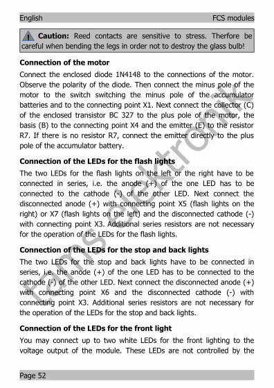
Caution: Reed contacts are sensitive to stress. Therfore becareful when bending the legs in order not to destroy the glass bulb!
Connection of the motor
Connect the enclosed diode 1N4148 to the connections of the motor.Observe the polarity of the diode. Then connect the minus pole of themotor to the switch switching the minus pole of the accumulatorbatteries and to the connecting point X1. Next connect the collector (C)of the enclosed transistor BC 327 to the plus pole of the motor, thebasis (B) to the connecting point X7 and the emitter (E) to the resistorR7. If there is no resistor R7, connect the emitter directly to the pluspole of the accumulator batteries.
Connection of the dim switch
Connect the connecting points X2, X3 and X5 of the dimming switch tothe connecting points X5, X3 and X2 of the FCS-2.
Next connect the enclosed light depending resistor to the connectingpoints X3 and X4 of the Dim switch. The light sensitive resistor has tobe placed that way it is exposed to the ambient lighting when thehousing of the vehicle is closed.
Page 49

tams e
lektro
nik
English FCS modules
Connection of the LEDs for the front and back lights
The two LEDs for the front lights have to be connected in parallel, i.e.the anodes (+) of the LEDs both have to be connected to X4. Connectthe two cathodes (-) to the resistors R8 and R9 (10 ). Connect thedisconnected ends of the resistors to the connecting point X3.
The two LEDs for the stop and back lights have to be connected inseries, i.e. the anode (+) of the one LED has to be connected to thecathode (-) of the other LED. Connect the disconnected anode (+) toconnecting point X6 and the disconnected cathode (-) to connectingpoint X3. Additional series resistors are not necessary for the operationof the LEDs for the stop and back lights.
Setting the sensitivity of the light
Before closing the housing of the vehicle, you should set the sensitivityof the dim switch to the desired lighting conditions. First set the trimpot to mid-position and change the sensitivity as far as necessary. Thecircuit requires 3 or 4 seconds to react.
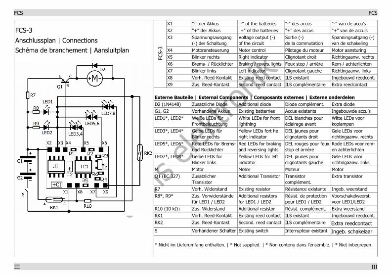
7.3. Mounting the FCS-3
Preparation
Open the housing of the vehicle. Locate the position for the module.Disconnect all connections from the accumulator batteries, the motorand the mounted reed contact except for the wire to the chargingcontact.
Follow the connection diagram in the centre of this handbook and theexplanations to the special features of the additional components(section 6).
In many vehicles the resistor R7 shown in the connection diagram ismounted into the lead-in wire to the motor. The resistor has to beconnected to the plus pole of the accumulator batteries if not yetmounted that way. If there is no resistor, R7 is not applicable.
Page 50
tams e
lektro
nik!
FCS modules English
Connection to the supply voltage
Connect the connecting point X2 to the plus pole of the accumulatorbatteries and the minus pole of the accumulator batteries to theexisting switch S of the vehicle. Connect the second pole of the switchto the connecting point X1.
Caution: The module should not be connected the wrong wayround. Otherwise it will be damaged when put into operation!
Connection of the existing reed contact
The existing reed contact has three connecting points, one at side Aand two at side B. Connect the connecting point at side A to theconnecting point X2 and the plus pole of the accumulator battery.
In order to check which one of the two connecting points of side B youhave to connect to the module, connect temporarily the minus pole ofthe motor to the minus pole of the accumulator battery and the pluspole of the motor to one of the two connecting points at side B of thereed contact. If the motor does not run with this connection, you haveto connect this connecting point to the connecting point X8 and theenclosed resistor R10. If the motor runs with this connection, you haveto connect the other connecting point to the connecting point X8 andthe enclosed resistor R10. Finally disconnect the temporary connectionsof the motor. Connect the second side of the resistor R10 to theconnecting point X3.
Connection of an additional reed contact
If the vehicle is intended to stop abruptly, the connecting point X9 isnot connected and you can skip this section. In order to brake thevehicle gently, an additional reed contact has to be connected, whichshould be mounted as far as possible in the front of the vehicle.Connect the enclosed reed contact to the connecting points X3 and X9.
Page 51
tams e
lektro
nik!
English FCS modules
Caution: Reed contacts are sensitive to stress. Therfore becareful when bending the legs in order not to destroy the glass bulb!
Connection of the motor
Connect the enclosed diode 1N4148 to the connections of the motor.Observe the polarity of the diode. Then connect the minus pole of themotor to the switch switching the minus pole of the accumulatorbatteries and to the connecting point X1. Next connect the collector (C)of the enclosed transistor BC 327 to the plus pole of the motor, thebasis (B) to the connecting point X4 and the emitter (E) to the resistorR7. If there is no resistor R7, connect the emitter directly to the pluspole of the accumulator battery.
Connection of the LEDs for the flash lights
The two LEDs for the flash lights on the left or the right have to beconnected in series, i.e. the anode (+) of the one LED has to beconnected to the cathode (-) of the other LED. Next connect thedisconnected anode (+) with connecting point X5 (flash lights on theright) or X7 (flash lights on the left) and the disconnected cathode (-)with connecting point X3. Additional series resistors are not necessaryfor the operation of the LEDs for the flash lights.
Connection of the LEDs for the stop and back lights
The two LEDs for the stop and back lights have to be connected inseries, i.e. the anode (+) of the one LED has to be connected to thecathode (-) of the other LED. Next connect the disconnected anode (+)with connecting point X6 and the disconnected cathode (-) withconnecting point X3. Additional series resistors are not necessary forthe operation of the LEDs for the stop and back lights.
Connection of the LEDs for the front light
You may connect up to two white LEDs for the front lighting to thevoltage output of the module. These LEDs are not controlled by the
Page 52

tams e
lektro
nik!
!
FCS modules English
stored software. They light as soon as the module is connected to thepower supply.
Connect the anodes (+) of the LEDs to the soldering point X2 and thecathodes (-) to the soldering point X3.
Caution: The LEDs for the front lighting must be operated viaseries resistors (recommended value: 100 ). Otherwise theconnected LEDs are damaged and the circuit may not work asintended.
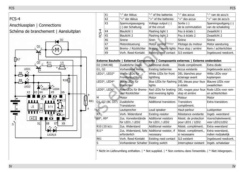
7.4. Mounting the FCS-4
Preparation
Open the housing of the vehicle. Locate the position for the module.Disconnect all connections from the accumulator batteries, the motorand the mounted reed contact except for the wire to the chargingcontact.
Follow the connection diagram in the centre of this handbook and theexplanations to the special features of the additional components(section 6).
In many vehicles the resistor R7 shown in the connection diagram ismounted into the lead-in wire to the motor. The resistor has to beconnected to the plus pole of the accumulator batteries if not yetmounted that way. If there is no resistor, R7 is not applicable.
Connection to the supply voltage
Connect the connecting point X2 to the plus pole of the accumulatorbatteries and the minus pole of the accumulator batteries to theexisting switch S of the vehicle. Connect the second pole of the switchto the connecting point X1.
Caution: The module should not be connected the wrong wayround. Otherwise it will be damaged when put into operation!
Page 53

tams e
lektro
nik
English FCS modules
Connection of the existing reed contact
The existing reed contact has three connecting points, one at side Aand two at side B. Connect the connecting point at side A to theconnecting point X1 and the existing switch S.
In order to check which one of the two connecting points of side B youhave to connect to the module, connect temporarily the plus pole of themotor to the plus pole of the accumulator batteries and the minus poleof the motor to one of the two connecting points at side B of the reedcontact. If the motor does not run with this connection, you have toconnect this connecting point to the plus pole of the motor and theother connecting point of the reed contact with the connecting point X9and the enclosed resistor R10. If the motor runs with this connection,you have to make the connections the other way round. Connect thesecond side of the resistor R10 to the connecting point X3.
Connection of the motor
Connect the enclosed diode 1N4148 to the connections of the motor.Observe the polarity of the diode. Then connect the minus pole of themotor to the switch switching the minus pole of the accumulatorbatteries and to the connecting point X1. Next connect the collector (C)of the enclosed transistor BC 327 to the plus pole of the motor, thebasis (B) to the connecting point X7 and the emitter (E) to the resistorR7. If there is no resistor R7, connect the emitter directly to the pluspole of the accumulator batteries.
Connection of the LEDs for the flashing lights
Connect the anodes (+) of the two LEDs for the flashing lights to theconnecting points X4 and X5. Connect the cathodes (-) of the LEDsboth to the connecting point X3. Additional series resistors are notnecessary for the operation of the LEDs for the flashing lights.
Page 54

tams e
lektro
nik
!
FCS modules English
Connection of the LEDs for the stop and back lights
The two LEDs for the stop and back lights have to be connected inseries, i.e. the anode (+) of the one LED has to be connected to thecathode (-) of the other LED. Next connect the disconnected anode (+)with connecting point X8 and the disconnected cathode (-) withconnecting point X3. Additional series resistors are not necessary forthe operation of the LEDs for the stop and back lights.
Connection of the loudspeaker
First connect the basis (B) of the enclosed transistor BC 327 to theconnecting point X6, the emitter (E) to the plus pole of the accumulatorbatteries and the collector (C) to the plus pole of the loudspeaker. Nextconnect the minus pole of the loudspeaker to the connecting point X1.If the polarity of the loudspeaker is not given, you may connect itanyway.
You can reduce the sound volume of the loudspeaker by mounting aresistor between the collector of the transistor and the plus pole of theloudspeaker. The resistor should have a value of 10 to 100 .
Connection of the diodes for the front light
You may connect up to two white LEDs for the front lighting to thevoltage output of the module. These LEDs are not controlled by thestored software. They light as soon as the module is connected to thepower supply.
Connect the anodes (+) of the LEDs to the soldering point X2 and thecathodes (-) to the soldering point X3.
Caution: The LEDs for the front lighting must be operated viaseries resistors (recommended value: 100 ). Otherwise theconnected LEDs are damaged and the circuit may not work asintended.
Page 55

tams e
lektro
nik!
English FCS modules
7.5. Mounting the FCS-L
Preparation
Open the housing of the vehicle. Locate the position for the module.Follow the connection diagram below.
Connection to the supply voltage
The module is designed for connecting to a supply voltage of 0,9 to1,8 V (= one accumulator battery). If it is connected to a higher supplyvoltage of 1,6 bis 2,5 V (= two accumulator batteries) you have toreduce the input voltage by mounting a diode (e.g. 1N4148) in thelead-in wire.
Connect the soldering point X1 to the positive pole and the solderingpoint X2 to the negative pole of the accumulator batteries.
Caution: The module should not be connected the wrong wayround. Otherwise it will be damaged when put into operation!
Connection of the diodes
Connect the LEDs´anodes (+) and cathodes (-), as in the connectioningdiagram, to the soldering points X3 and X4. The module is a constant-current source, therefore the mounting of additional series resistors isnot necessary.
Connections diagram FCS-L
Page 56

tams e
lektro
nik!
FCS modules English
D1, D2 LED, white (not supplied)
D3, D4 LED, red (not supplied)
D5 if required, e.g. diode 1N4148
X1 connection to "+" of the accumulator batteries
X2 connection to "-" of the accumulator batteries
X3 connection to the cathode side of the LEDs (-)
X4 connection to the anode side of the LEDs (+)
8. Check list for troubleshooting
Parts are getting very hot and/or start to smoke.
Disconnect the system from the mains immediately!
Possible cause: The connections to the power supply are connectedthe wrong round. à Check the connection. In this case the moduleis probably damaged irreparably.
The LEDs do not light / flash.Possible cause: The LEDs are connected the wrong round. à Checkthe connections.
Possible cause: The power supply is interrupted. à Check theconnections.
FCS-L: After applying the supply voltage the LEDs flash quickly andthen go out.Possible cause: The supply voltage is higher than 1,8 V. à Reducethe input voltage, for instance by mounting a diode in the lead-inwire from the power supply to the module.
FCS-L: The red or the white LEDs light brighter than the others. Possible cause: The burning voltage of the red and the white LEDsdiffers considerably. à Connect a series resistor (value from 1 to20 W) to the LEDs that light brighter.
Page 57

tams e
lektro
nik
English FCS modules
FCS-2 bis -4: The vehicle does not drive.Possible cause: The wrong connecting point at side B of the existingreed contact was used. à Check the connection.
FCS-2 bis -4: The vehicle drives backwards.Possible cause: The connections of the motor are connected reverse.à Check the connections.
FCS-4: The siren does not work.Possible cause: The connections of the transistor are reversed.à Check the connections.
Possible cause: The power supply is interrupted. à Check theconnections.
Possible cause: The vehicle halts at a stop. This is no a fault. Thesiren is switched off while the vehicle is halting.
Hotline: If problems with your module occur, our hotline is pleased to help you (mail address on the last page).
Repairs: You can send in a defective module for repair (address on thelast page). In case of guarantee the repair is free of charge for you.With damages not covered by guarantee, the maximum fee for therepair is 50 % of the sales price according to our valid price list. Wereserve the right to reject the repairing of a module when the repair isimpossible for technical or economic reasons.
Please do not send in modules for repair charged to us. In case ofwarranty we will reimburse the forwarding expenses up to the flat ratewe charge according to our valid price list for the delivery of theproduct. With repairs not covered by guarantee you have to bear theexpenses for sending back and forth.
Page 58
tams e
lektro
nik
FCS modules English
9. Guarantee bond
For this product we issue voluntarily a guarantee of 2 years from thedate of purchase by the first customer, but in maximum 3 years afterthe end of series production. The first customer is the consumer firstpurchasing the product from us, a dealer or another natural or juristicperson reselling or mounting the product on the basis of self-employment. The guarantee exists supplementary to the legal warrantyof merchantability due to the consumer by the seller.
The warranty includes the free correction of faults which can be provedto be due to material failure or factory flaw. With kits we guaranteethe completeness and quality of the components as well as the functionof the parts according to the parameters in not mounted state. Weguarantee the adherence to the technical specifications when the kithas been assembled and the ready-built circuit connected according tothe manual and when start and mode of operation follow theinstructions.
We retain the right to repair, make improvements, to deliver spares orto return the purchase price. Other claims are excluded. Claims forsecondary damages or product liability consist only according to legalrequirements.
Condition for this guarantee to be valid, is the adherence to themanual. In addition, the guarantee claim is excluded in the followingcases:
if arbitrary changes in the circuit are made, if repair attempts have failed with a ready-built module or device, if damaged by other persons, if damaged by faulty operation or by careless use or abuse.
Page 59
tams e
lektro
nik
English FCS modules
10. EU declaration of conformity
This product conforms with the EC-directives mentioned belowand is therefore CE certified.
2004/108/EG on electromagnetic. Underlying standards: EN 55014-1and EN 61000-6-3. To guarantee the electromagnetic tolerance inoperation you must take the following precautions:
Connect the transformer only to an approved mains socket installedby an authorised electrician.
Make no changes to the original parts and accurately follow theinstructions, connection diagrams and PCB layout included with thismanual.
Use only original spare parts for repairs.
2011/65/EG on the restriction of the use of certain hazardoussubstances in electrical and electronic equipment (ROHS). Underlyingstandard: EN 50581.
11. Declarations conforming to the WEEE directive
This product conforms with the EC-directive 2012/19/EG onwaste electrical and electronic equipment (WEEE).
Don´t dispose of this product in the house refuse, bring it to the nextrecycling bay.
The asterisks **
This manual mentions the following companies:
Gebr. Faller GmbH | Kreuzstraße 9 | DE-78148 Gütenbach
Page 60
tams e
lektro
nik
FCS FCS
FCS-1
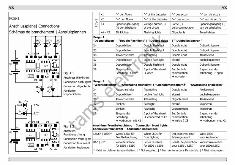
Anschlusspläne| ConnectionsSchémas de branchement | Aansluitplannen
Fig. 1.1Anschluss Blinklichter
Connection flash lights
Connexion clignotants
Aansluiten knipperlichten
Fig. 1.2Anschluss Frontbeleuchtung
Connection front lights
Connexion feux avant
Aansluiten koplampen
FCS-
1
X1 "-" der Akkus "-" of the batteries "-" des accus "-" van de accu’s
X2 "+" der Akkus "+" of the batteries "+" des accus "+" van de accu’s
X3 Spannungsausgang (-) der Schaltung
Voltage output (-) of the circuit
Sortie (-) de la commutation
Spanningsuitgang (-)van de schakeling
X4 – X9 Blinklichter Flashing lights Clignotants Zwaailichten
Progr. 1 "Doppelblitzen" | "Double flashlight" | " Double éclat " | " Dubbelknipperen "
X4 Doppelblitzen Double flashlight Double éclat Dubbelknipperen
X5 Doppelblitzen Double flashlight Double éclat Dubbelknipperen
X6 Abwechselndes Alternating Double éclat Afwisselend
X7 Doppelblitzen double flashlight alterné dubbelknipperen
X8 Doppelblitzen Double flashlight Double éclat Dubbelknipperen
X9 Eingang der Schaltung à offen
Input of the circuit à open
Entrée de la commutationà ouverte
Ingang van de schakeling à open
Progr. 2 "Wechselblinken" | "Alternating flashlight" | "Clignotement alterné" | "Afwisselend knipperen"
X4 Abwechselndes Alternating Double éclat Afwisselend
X5 Doppelblitzen double flashlight alterné dubbelknipperen
X6 Abwechselndes Alternating Clignotement Afwisselend
X7 Blinken flashlight alterné knipperen
X8 Blinken flashlight Clignotement knipperen
X9 Eingang der Schaltungà verbunden mit X3
Input of the circuità connected to X3
Entrée de la commutationà reliée à X3
Ingang van de schakelingà verbonden met X3
Anschluss Frontbeleuchtung | Connection front lightsConnexion feux avant | Aansluiten koplampen
LED6* | LED7* Weiße LEDs fürFrontbeleuchtung
White LEDs for front lighting
DEL blanches pouréclairage avant
Witte LEDs voor koplampen
R6* | R7* Vorwiderständefür LED6 / LED7
Series resistorsfor LED6 / LED6
Résist. de protectionpour LED6 / LED7
Voorschakelweerst. voor LED1/LED2
* Nicht im Lieferumfang enthalten. | * Not supplied. | * Non contenu dans l’ensemble. | * Niet inbegrepen.
I I
tams e
lektro
nik
FCS FCS
FCS-2
Anschlussplan | ConnectionsSchéma de branchement | Aansluitplan
FCS-
2
X1 "-" der Akkus "-" of the batteries "-" des accus "-" van de accu’s
X2 "+" der Akkus "+" of the batteries "+" des accus "+" van de accu’s
X3 Spannungsausgang (-) der Schaltung
Voltage output (-) of the circuit
Sortie (-) de la commutation
Spanningsuitgang (-)van de schakeling
X4 Frontbeleuchtung Front lighting Feux avant Koplampen
X5 Dämmerungsschalter Light sensitive switch Interrupt. crépuscul. Lichtgevoel. schakel.
X6 Brems- / Rücklichter Braking / revers. lights Feux stop / arrière Rem-/ achterlichten
X7 Motorsteuerung Motor control Pilotage du moteur Motor aansturing
X8 Vorh. Reed-Kontakt Existing reed contact ILS existant Ingebouwd reedcont.
X9 Zus. Reed-Kontakt Second. reed contact ILS complémentaire Extra reedcontact
Externe Bauteile | External Components | Composants externes | Externe onderdelen
D2 (1N4148) Zusätzliche Diode Additional diode Diode complément. Extra diode
G1, G2 Vorhandene Akkus Existing batterries Accus existants Ingebouwde accu’s
LED1*, LED2* Weiße LEDs fürFrontbeleuchtung
White LEDs for front lighting
DEL blanches pouréclairage avant
Witte LEDs voor koplampen
LED3*, LED4* Rote LEDs für Brems-und Rücklichter
Red LEDs for brakingand reversing lights
DEL rouges pour feux stop et arrière
Rode LEDs voor rem-en achterlichten
DS-1 Dämmerungsschalter Dim switch Interrupteur crépusculaire
Lichtgevoelige schakelaar
M Motor Motor Moteur Motor
Q1 (BC 327) Zus. Transistor Additional Transistor Transistor complém. Extra transistor
R7 Vorh. Widerstand Existing resistor Résistance existante Ingeb. weerstand
R8, R9 (10 W) Vorwiderständefür LED1 / LED2
Series resistorsfor LED1 / LED2
Résist. de protectionpour LED1 / LED2
Voorschakelweerst. voor LED1/LED2
R10 (10 kW) Zus. Widerstand Additional resistor Résist. complément. Extra weerstand
R11 Lichtabhängiger Widerstand
Light sensitiveresistor
Photorésistance Lichtgevoelige weerstand
RK1 Vorh. Reed-Kontakt Existing reed contact ILS existant Ingebouwd reedcont.
RK2 Zus. Reed-Kontakt Second. reed contact ILS complémentaire Extra reedcontact
S Vorh. Schalter Existing switch Interrupteur existant Ingeb. schakelaar
* Nicht im Lieferumfang enthalten. | * Not supplied. | * Non contenu dans l’ensemble. | * Niet inbegrepen.
II II
tams e
lektro
nik
FCS FCS
FCS-3
Anschlussplan | ConnectionsSchéma de branchement | Aansluitplan
FCS-
3
X1 "-" der Akkus "-" of the batteries "-" des accus "-" van de accu’sX2 "+" der Akkus "+" of the batteries "+" des accus "+" van de accu’s X3 Spannungsausgang
(-) der SchaltungVoltage output (-) of the circuit
Sortie (-) de la commutation
Spanningsuitgang (-)van de schakeling
X4 Motoransteuerung Motor control Pilotage du moteur Motor aansturing X5 Blinker rechts Right indicator Clignotant droit Richtingaanw. rechtsX6 Brems- / Rücklichter Braking / revers. lights Feux stop / arrière Rem-/ achterlichtenX7 Blinker links Left indicator Clignotant gauche Richtingaanw. linksX8 Vorh. Reed-Kontakt Existing reed contact ILS existant Ingebouwd reedcont.X9 Zus. Reed-Kontakt Second. reed contact ILS complémentaire Extra reedcontact
Externe Bauteile | External Components | Composants externes | Externe onderdelen D2 (1N4148) Zusätzliche Diode Additional diode Diode complément. Extra diode G1, G2 Vorhandene Akkus Existing batterries Accus existants Ingebouwde accu’s LED1*, LED2* Weiße LEDs für
FrontbeleuchtungWhite LEDs for front lighthing
DEL blanches pour éclairage avant
Witte LEDs voor koplampen
LED3*, LED4* Gelbe LEDs für Blinker rechts
Yellow LEDs fort he right indicator
DEL jaunes pour clignotants droit
Gele LEDs voor richtingaanw. rechts
LED5*, LED6* Rote LEDs für Brems-und Rücklichter
Red LEDs for braking and reversing lights
DEL rouges pour feuxstop et arrière
Rode LEDs voor rem- en achterlichten
LED7*, LED8* Gelbe LEDs für Blinker links
Yellow LEDs for left indicator
DEL jaunes pour clignotants gauche
Gele LEDs voor richtingaanw. links
M Motor Motor Moteur MotorQ1 (BC 327) Zusätzlicher
Transistor Additional Transistor Transistor
complément. Extra transistor
R7 Vorh. Widerstand Existing resistor Résistance existante Ingeb. weerstandR8*, R9* Zus. Vorwiderstände
für LED1 / LED2 Additional resistorsfor LED1 / LED2
Résist. de protectionpour LED1 / LED2
Voorschakelweerst. voor LED1/LED2
R10 (10 kW) Zus. Widerstand Additional resistor Résist. complément. Extra weerstand RK1 Vorh. Reed-Kontakt Existing reed contact ILS existant Ingebouwd reedcont.RK2 Zus. Reed-Kontakt Second. reed contact ILS complémentaire Extra reedcontactS Vorhandener Schalter Existing switch Interrupteur existant Ingeb. schakelaar
* Nicht im Lieferumfang enthalten. | * Not supplied. | * Non contenu dans l’ensemble. | * Niet inbegrepen.
III III
tams e
lektro
nik
FCS FCS
FCS-4
Anschlussplan | ConnectionsSchéma de branchement | Aansluitplan
FCS-
4
X1 "-" der Akkus "-" of the batteries "-" des accus "-" van de accu’sX2 "+" der Akkus "+" of the batteries "+" des accus "+" van de accu’s X3 Spannungsausgang
(-) der SchaltungVoltage output (-) of the circuit
Sortie (-) de la commutation
Spanningsuitgang (-)van de schakeling
X4 Blaulicht 1 Flashing light 1 Feu à éclats 1 Zwaailicht 1X5 Blaulicht 2 Flashing light 2 Feu à éclats 2 Zwaailicht 2X6 Sirene Siren Sirène SireneX7 Motorsteuerung Motor control Pilotage du moteur Motor aansturing X8 Brems- / Rücklichter Braking / revers. lights Feux stop / arrière Rem-/ achterlichtenX9 Vorh. Reed-Kontakt Existing reed contact ILS existant Ingebouwd reedcont.
Externe Bauteile | External Components | Composants externes | Externe onderdelen D2 (1N4148) Zusätzliche Diode Additional diode Diode complément. Extra diode G1, G2 Vorhandene Akkus Existing batterries Accus existants Ingebouwde accu’s LED1*, LED2* Weiße LEDs für
FrontbeleuchtungWhite LEDs for front lighthing
DEL blanches pour éclairage avant
Witte LEDs voor koplampen
LED3*, LED4* Blaue LEDs für Blaulichter
Blue LEDs for flashinglights
DEL bleues pour feuxà éclats
Blauwe LEDs voor zwaailichten
LED5*, LED6* Rote LEDs für Brems-und Rücklichter
Red LEDs for braking and reversing lights
DEL rouges pour feuxstop et arrière
Rode LEDs voor rem- en achterlichten
M Motor Motor Moteur MotorQ1, Q2 (BC 327) Zusätzliche
Transistoren Additional transistors Transistors
complément. Extra transistors
LS Lautsprecher Loud speaker Haut-parleur LuidsprekerR7 Vorh. Widerstand Existing resistor Résistance existante Ingeb. weerstandR8*, R9* Zus. Vorwiderstände
für LED1 / LED2 Additional resistorsfor LED1 / LED2
Résist. de protectionpour LED1 / LED2
Voorschakelweerst. voor LED1/LED2
R10 (10 kW) Zus. Widerstand Additional resistor Résist. complément. Extra weerstand R11* Zus. Widerstand, falls
erforderlich Additional resistor, if necessary
Résist. complément., si necessaire
Extra weerstand, indien nodzakelijk
RK1 Vorh. Reed-Kontakt Existing reed contact ILS existant Ingebouwd reedcont.S Vorhandener Schalter Existing switch Interrupteur existant Ingeb. schakelaar
* Nicht im Lieferumfang enthalten. | * Not supplied. | * Non contenu dans l’ensemble. | * Niet inbegrepen.
IV IV

tams e
lektro
nik
n
n
Aktuelle Informationen und Tipps:
Information and tips:
Informations et conseils:
Actuele informatie en tips:
n
n
http://www.tams-online.de n
n
n
Garantie und Service:
Warranty and service:
Garantie et service:
Garantie en service:
n
n
Tams Elektronik GmbH n
Fuhrberger Straße 4
DE-30625 Hannover
fon: +49 (0)511 / 55 60 60
fax: +49 (0)511 / 55 61 61
e-mail: [email protected]
n
n
n
n