FCoE – Design, Operations and Management Best...
121
© 2012 Cisco and/or its affiliates. All rights reserved. Presentation_ID Cisco Public FCoE – Design, Operations and Management Best Practices BRKSAN2047 1
-
Upload
truongcong -
Category
Documents
-
view
216 -
download
0
Transcript of FCoE – Design, Operations and Management Best...

© 2012 Cisco and/or its affiliates. All rights reserved. Presentation_ID Cisco Public
FCoE – Design, Operations and Management Best Practices BRKSAN2047
1

© 2012 Cisco and/or its affiliates. All rights reserved. Presentation_ID Cisco Public
FCoE - Design, Operations and Management Best Practices Agenda
§ Unified Fabric – What and When § FCoE Protocol Fundamentals § Nexus FCoE Capabilities
§ FCoE Network Requirements and Design Considerations
§ DCB & QoS - Ethernet Enhancements § Single Hop Design § Multi-Hop Design
§ Futures
1K Cisco Nexus
x86
© 2012 Cisco and/or its affiliates. All rights reserved. Presentation_ID Cisco Public
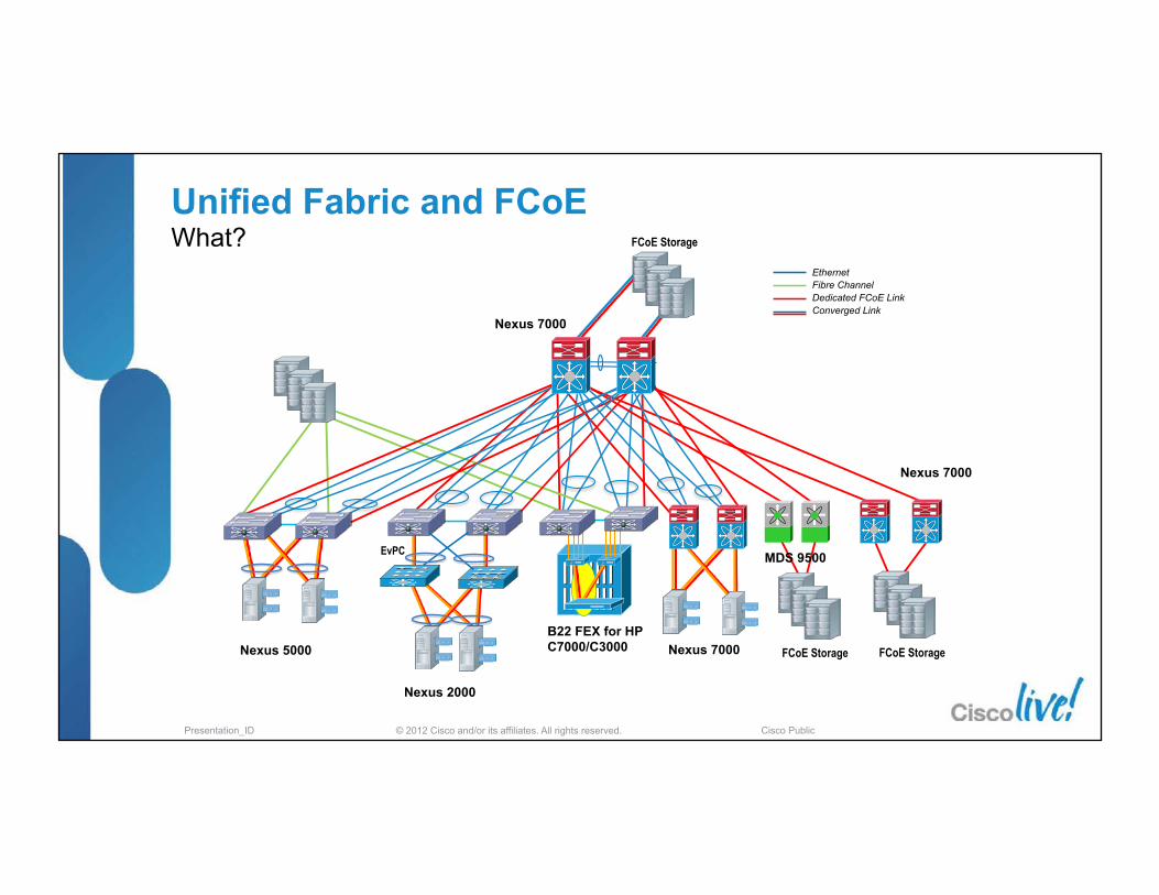
FCoE Storage
VNP
Nexus 5000
Nexus 2000
Nexus 7000
MDS 9500
FCoE Storage
Ethernet Fibre Channel Dedicated FCoE Link Converged Link
FCoE Storage
Nexus 7000
B22 FEX for HP C7000/C3000
EvPC
Nexus 7000
Unified Fabric and FCoE What?
© 2012 Cisco and/or its affiliates. All rights reserved. Presentation_ID Cisco Public
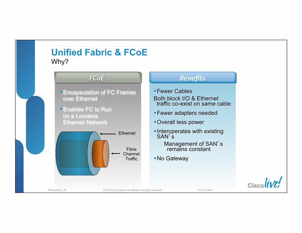
§ Encapsulation of FC Frames over Ethernet
§ Enables FC to Run on a Lossless Ethernet Network
§ Fewer Cables Both block I/O & Ethernet traffic co-exist on same cable
§ Fewer adapters needed § Overall less power § Interoperates with existing SAN’s
Management of SAN’s remains constant
§ No Gateway
FCoE Benefits
Fibre Channel Traffic
Ethernet
Unified Fabric & FCoE Why?

© 2012 Cisco and/or its affiliates. All rights reserved. Presentation_ID Cisco Public
Unified Fabric Why?
§ Embedded on Motherboard § Integrated into O/S § Many Suppliers
§ Mainstream Technology § Widely Understood
§ Interoperability by Design
Always a stand alone Card
Specialized Drivers
Few Suppliers
Specialized Technology
Special Expertise
Interoperability by Test
Ethernet Economic Model FC Economic Model

© 2012 Cisco and/or its affiliates. All rights reserved. Presentation_ID Cisco Public
iSCSI Appliance
File System
Applica�on
SCSI Device Driver iSCSI Driver TCP/IP Stack
NIC
Volume Manager
NIC
TCP/IP Stack
iSCSI Layer Bus Adapter
iSCSI Gateway
FC
File System
Applica�on
SCSI Device Driver iSCSI Driver TCP/IP Stack
NIC
Volume Manager
NIC
TCP/IP Stack
iSCSI Layer FC HBA
NAS Appliance
NIC TCP/IP Stack
I/O Redirector
File System
Applica�on
NFS/CIFS
NIC TCP/IP Stack
File System Device Driver
Block I/O
NAS Gateway
NIC TCP/IP Stack
I/O Redirector
File System
Applica�on
NFS/CIFS
FC
NIC
TCP/IP Stack
File System FC HBA
FCoE SAN
FCoE
SCSI Device Driver
File System
Applica�on
Computer System Computer System Computer System Computer System Computer System
Block I/O File I/O
Ethernet Ethernet
Block I/O NIC
Volume Manager Volume Manager
FCoE Driver
Ethernet Ethernet Ethernet
§ Ability to re-‐provision any compute unit to leverage any access method to the data stored on the ‘spindle’
§ Serialized Re-‐Use – (e.g. Boot from SAN and Run from NAS)
§ Virtualiza�on requires that the Storage Fabric needs to exist everywhere the IP fabric does
Unified Fabric Why?
© 2012 Cisco and/or its affiliates. All rights reserved. Presentation_ID Cisco Public
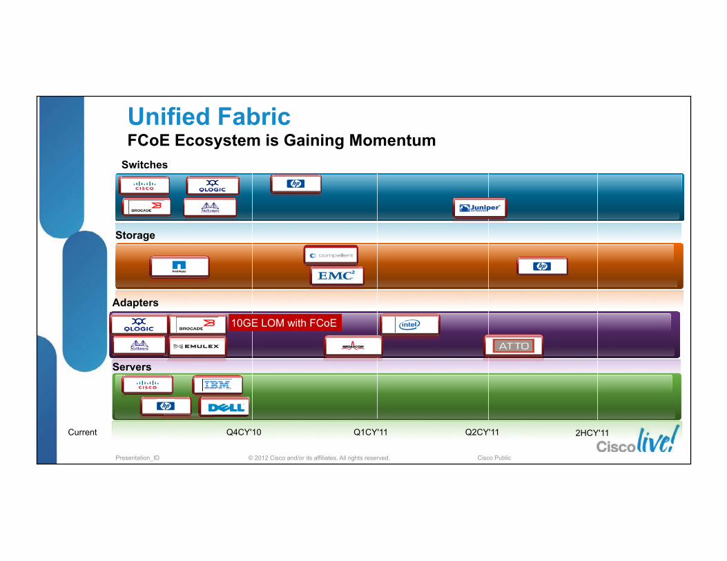
Unified Fabric FCoE Ecosystem is Gaining Momentum
Adapters
Servers
Current Q4CY'10 Q1CY'11 2HCY'11 Q2CY'11
Switches
Storage
10GE LOM with FCoE

© 2012 Cisco and/or its affiliates. All rights reserved. Presentation_ID Cisco Public
Source: Infone�cs
Unified Fabric & FCoE When? – FCoE Projected Growth

© 2012 Cisco and/or its affiliates. All rights reserved. Presentation_ID Cisco Public
FCoE - Design, Operations and Management Best Practices Agenda
§ Unified Fabric – What and When § FCoE Protocol Fundamentals § Nexus FCoE Capabilities
§ FCoE Network Requirements and Design Considerations
§ DCB & QoS - Ethernet Enhancements § Single Hop Design § Multi-Hop Design
§ Futures
1K Cisco Nexus
x86

© 2012 Cisco and/or its affiliates. All rights reserved. Presentation_ID Cisco Public
FCoE Protocol Fundamentals Standards for I/O Consolidation
FCoE
www.T11.org
Fibre Channel on
network media FC-
BB-5
PFC
DCB
IEEE 802.1
ETS DCBx
IEEE 802.1Qbb Priority-‐based Flow Control
IEEE 802.1Qaz Priority Grouping
Enhanced Transmission Selec�on
IEEE 802.1Qaz Configura�on Verifica�on
Completed June 2009 Published by ANSI in May 2010
Completed March 2011 Forwarded to RevCom for publication

© 2012 Cisco and/or its affiliates. All rights reserved. Presentation_ID Cisco Public
Ethe
rnet
He
ader
FCoE
He
ader
FC
Head
er
FC Payload CRC
EOF
FCS
Destination MAC Address
Source MAC Address (IEEE 802.1Q Tag)
ET = FCoE Ver Reserved Reserved Reserved
Reserved SOF
Encapsulated FC Frame (with CRC)
EOF Reserved FCS
Byte 0 Byte 2197
FCoE Frame Format Bit 0 Bit 31 § Fibre Channel over Ethernet provides a
high capacity and lower cost transport op�on for block based storage
§ Two protocols defined in the standard
§ FCoE – Data Plane Protocol
§ FIP – Control Plane Protocol
§ FCoE is a standard -‐ June 3rd 2009, the FC-‐BB-‐5 working group of T11 completed its work and unanimously approved a final standard for FCoE
§ FCoE ‘is’ Fibre Channel
FCoE Protocol Fundamentals Fibre Channel over Ethernet (FCoE)

© 2012 Cisco and/or its affiliates. All rights reserved. Presentation_ID Cisco Public
FCoE § Data Plane § It is used to carry most of the
FC frames and all the SCSI traffic
§ Uses Fabric Assigned MAC address (dynamic) : FPMA
§ IEEE-assigned Ethertype for FCoE traffic is 0x8906
FIP (FCoE Initialization Protocol) § It is the control plane protocol
§ It is used to discover the FC entities connected to an Ethernet cloud
§ It is also used to login to and logout from the FC fabric
§ Uses unique BIA on CNA for MAC
§ IEEE-assigned Ethertype for FCoE traffic is 0x8914
http://www.cisco.biz/en/US/prod/collateral/switches/ps9441/ps9670/white_paper_c11-560403.html
FC-BB-5 defines two protocols required for an FCoE enabled Fabric
FCoE Protocol Fundamentals Protocol Organization – Data and Control Plane

© 2012 Cisco and/or its affiliates. All rights reserved. Presentation_ID Cisco Public
FCoE Protocol Fundamentals It’s Fibre Channel Control Plane + FIP
§ From a Fibre Channel standpoint it’s ‒ FC connectivity over a new type of cable called… Ethernet
§ From an Ethernet standpoints it’s ‒ Yet another ULP (Upper Layer Protocol) to be transported
FC-0 Physical Interface
FC-1 Encoding
FC-2 Framing & Flow Control
FC-3 Generic Services
FC-4 ULP Mapping
Ethernet Media Access Control
Ethernet Physical Layer
FC-2 Framing & Flow Control
FC-3 Generic Services
FC-4 ULP Mapping
FCoE Logical End Point

© 2012 Cisco and/or its affiliates. All rights reserved. Presentation_ID Cisco Public
§ Neighbour Discovery and Configuration (VN – VF and VE to VE)
§ Step 1: FCoE VLAN Discovery § FIP sends out a multicast to ALL_FCF_MAC address
looking for the FCoE VLAN § FIP frames use the native VLAN
§ Step 2: FCF Discovery § FIP sends out a multicast to the ALL_FCF_MAC address
on the FCoE VLAN to find the FCFs answering for that FCoE VLAN
§ FCF’s responds back with their MAC address
§ Step 3: Fabric Login § FIP sends a FLOGI request to the FCF_MAC found in
Step 2 § Establishes a virtual link between host and FCF
Enode Initiator
FCoE Switch FCF
VLAN Discovery
FLOGI/FDISC
FLOGI/FDISC Accept
FC Command
FC Command Responses
FCoE Initialization
Protocol (FIP)
FCoE Protocol
VLAN Discovery
FCF Discovery
Solicitation FCF
Discovery Advertisement
FCoE Protocol Fundamentals FCoE Initialization Protocol (FIP)
** FIP does not carry any Fibre Channel frames

© 2012 Cisco and/or its affiliates. All rights reserved. Presentation_ID Cisco Public
§ FCF (Fibre Channel Forwarder) is the Fibre Channel switching element inside an FCoE switch § Fibre Channel logins (FLOGIs) happens at the FCF
§ Consumes a Domain ID
§ FCoE encap/decap happens within the FCF
§ Forwarding based on FC information
Eth port
Eth port
Eth port
Eth port
Eth port
Eth port
Eth port
Eth port
Ethernet Bridge
FC port
FC port
FC port
FC port
FCF
FCoE Switch FC Domain ID : 15
FCoE Protocol Fundamentals Fibre Channel Forwarder - FCF

© 2012 Cisco and/or its affiliates. All rights reserved. Presentation_ID Cisco Public
VE_Port
VF_Port
VF_Port
VE_Port
VN_Port
VN_Port
FCoE_NPV
Switch VF_Port VNP_Port FCF
Switch
End Node
End Node
FCoE Switch : FCF
FCoE Protocol Fundamentals Explicit Roles still defined in the Fabric
§ FCoE does not change the explicit port level relationships between devices (add a ‘V’ to the port type when it is an Ethernet wire) § Servers (VN_Ports) connect to Switches (VF_Ports) § Switches connect to Switches via Expansion Ports (VE_Ports)

© 2012 Cisco and/or its affiliates. All rights reserved. Presentation_ID Cisco Public
FCF FCF
Fibre Channel Drivers
Ethernet Drivers
Operating System
PCIe
Fibre Channel
Ethernet
10GbE
10GbE
Link
FCoE Protocol Fundamentals CNA: Converged Network Adapter § Converged Network Adapter (CNA) presents two PCI
address to the Operating System (OS)
§ OS loads two unique sets of drivers and manages two unique application topologies
§ Server participates in both topologies since it has two stacks and thus two views of the same ‘unified wire’
§ SAN Multi-Pathing provides failover between two fabrics (SAN ‘A’ and SAN ‘B’)
§ NIC Teaming provides failover within the same fabric (VLAN)
Ethernet Driver bound to
Ethernet NIC PCI address
FC Driver bound to FC
HBA PCI address
Data VLAN(s) are passed to the
Ethernet driver
FCoE VLAN terminates on the
CNA
Nexus Edge participates in both distinct FC and IP Core
topologies
§ Operating System sees:
Dual port 10 Gigabit Ethernet adapter Dual Port 4 Gbps Fibre Channel HBAs

© 2012 Cisco and/or its affiliates. All rights reserved. Presentation_ID Cisco Public
FCoE, Same Model as FC Connecting to the Fabric
CNA
ENode
FC Fabric
Target
Ethernet Fabric
DCB capable Switch acting as an FCF
Unified Wire
§ Same host to target communication § Host has 2 CNA’s (one per fabric) § Target has multiple ports to connect to
fabric § Connect to a capable switch
§ Port Type Negotiation (FC port type will be handled by FIP)
§ Speed Negotiation § DCBX Negotiation
§ Access switch is a Fibre Channel Forwarder (FCF)
§ Dual fabrics are still deployed for redundancy

© 2012 Cisco and/or its affiliates. All rights reserved. Presentation_ID Cisco Public
My port is up…can I talk now? FIP and FCoE Login Process
VN_Port
VF_Port
FIP Discovery
E_ports or VE_Port
§ Step 1: FIP Discovery Process § FCoE VLAN Discovery § FCF Discovery § Verifies Lossless Ethernet is capable of
FCoE transmission § Step 2: FIP Login Process
§ Similar to existing Fibre Channel Login process - sends FLOGI to upstream FCF
§ FCF assigns the host a Enode MAC address to be used for FCoE forwarding (Fabric Provided MAC Address - FPMA)
CNA
FC or FCoE Fabric
Target
ENode FC-MAP (0E-FC-xx)
FC-ID 7.8.9
FC-MAC Address
FC-MAP (0E-FC-xx)
FC-ID 10.00.01

© 2012 Cisco and/or its affiliates. All rights reserved. Presentation_ID Cisco Public
FCoE Protocol Fundamentals Fibre Channel over Ethernet Addressing Scheme § Enode FCoE MAC assigned for each FCID
§ Enode FCoE MAC composed of a FC-MAP and FCID
§ FC-MAP is the upper 24 bits of the Enode’s FCoE MAC
§ FCID is the lower 24 bits of the Enode’s MAC
§ FCoE forwarding decisions still made based on FSPF and the FCID within the Enode MAC
§ For different physical networks the FC-MAP is used as a fabric identifier
§ FIP snooping will use this as a mechanism in realizing the ACLs put in place to prevent data corruption
FC-‐MAP (0E-‐FC-‐xx)
FC-‐ID 7.8.9
FC-MAC Address
FC-‐MAP (0E-‐FC-‐xx)
FC-‐ID 10.00.01

© 2012 Cisco and/or its affiliates. All rights reserved. Presentation_ID Cisco Public
§ The FCoE VLAN is manually configured on the Nexus 5K
§ The FCF-MAC address is configured on the Nexus 5K by default once feature fcoe has been configured § This is the MAC address returned in step 2 of the FIP exchange § This MAC is used by the host to login to the FCoE fabric
** FIP does not carry any Fibre Channel frames
My port is up…can I talk now? FIP and FCoE Login Process

© 2012 Cisco and/or its affiliates. All rights reserved. Presentation_ID Cisco Public
Login complete…almost there Fabric Zoning
FC/FCoE Fabric
Initiator
Target
fcid 0x10.00.01 [pwwn 10:00:00:00:c9:76:fd:31] [tnitiator] fcid 0x11.00.01 [pwwn 50:06:01:61:3c:e0:1a:f6] [target]
pwwn 10:00:00:00:c9:76:fd:31
pwwn 50:06:01:61:3c:e0:1a:f6
FCF with Domain ID 10
§ Zoning is a feature of the fabric and is independent of Ethernet transport
§ Zoning can be configured on the Nexus 5000/7000 using the CLI or Fabric Manager
§ If Nexus 5000 is in NPV mode, zoning will be configured on the upstream core switch and pushed to the Nexus 5000
§ Devices acting as Fibre Channel Forwarders participate in the Fibre Channel security (Zoning) control
§ DCB ‘only’ bridges do not participate in zoning and require additional security mechanisms (ACL applied along the forwarding path on a per FLOGI level of granularity)

© 2012 Cisco and/or its affiliates. All rights reserved. Presentation_ID Cisco Public
§ Login process: show flogi database and show fcoe database show the logins and associated FCIDs, xWWNs and FCoE MAC addresses
Login complete Flogi and FCoE Databases are populated

© 2012 Cisco and/or its affiliates. All rights reserved. Presentation_ID Cisco Public
§ CE - Classical Ethernet (non lossless) § DCB & DCBx - Data Center Bridging, Data Center Bridging Exchange § FCF - Fibre Channel Forwarder (Nexus 5000, Nexus 7000, MDS 9000) § FIP – FCoE Initialization Protocol § Enode: a Fiber Channel end node that is able to transmit FCoE frames using one
or more Enode MACs. § FIP snooping Bridge § FCoE-NPV - Fibre Channel over IP N_Port Virtualization § Single hop FCoE : running FCoE between the host and the first hop access level
switch § Multi-hop FCoE : the extension of FCoE beyond a single hop into the Aggregation
and Core layers of the Data Centre Network § Zoning - Security method used in Storage Area Networks § FPMA – Fabric Provided Management Address
FCoE Protocol Fundamentals Summary of Terminology
For Your Reference
© 2012 Cisco and/or its affiliates. All rights reserved. Presentation_ID Cisco Public
FCoE - Design, Operations and Management Best Practices Agenda
§ Unified Fabric – What and When § FCoE Protocol Fundamentals § Nexus FCoE Capabilities
§ FCoE Network Requirements and Design Considerations
§ DCB & QoS - Ethernet Enhancements § Single Hop Design § Multi-Hop Design
§ Futures
1K Cisco Nexus
x86
© 2012 Cisco and/or its affiliates. All rights reserved. Presentation_ID Cisco Public
Servers, FCoE attached Storage
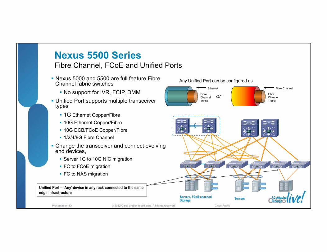
Nexus 5500 Series Fibre Channel, FCoE and Unified Ports
§ Nexus 5000 and 5500 are full feature Fibre Channel fabric switches § No support for IVR, FCIP, DMM
§ Unified Port supports multiple transceiver types § 1G Ethernet Copper/Fibre § 10G Ethernet Copper/Fibre § 10G DCB/FCoE Copper/Fibre § 1/2/4/8G Fibre Channel
§ Change the transceiver and connect evolving end devices, § Server 1G to 10G NIC migration § FC to FCoE migration § FC to NAS migration
FC Attached Storage
Servers
Unified Port – ‘Any’ device in any rack connected to the same edge infrastructure
Fibre Channel Traffic
Ethernet
or Fibre Channel Traffic
Fibre Channel
Any Unified Port can be configured as

© 2012 Cisco and/or its affiliates. All rights reserved. Presentation_ID Cisco Public
Nexus 5500 Series5548UP/5596UP – UPC (Gen-2) and Unified Ports
Eth Ports
Eth Ports Eth Eth
FC Ports
FC FC
Slot 1
Slot 2 GEM Slot 3 GEM Slot 4 GEM
§ With the 5.0(3)N1 and later releases each module can define any number of ports as Fibre Channel (1/2/4/8 G) or Ethernet (either 1G or 10G)
§ Initial SW releases supports only a continuous set of ports configured as Ethernet or FC within each ‘slot’ § Eth ports have to be the first set and they have to be one contiguous range
§ FC ports have to be second set and they have to be contiguous as well
§ Future SW release will support per port dynamic configuration
n5k(config)# slot <slot-num> n5k(config-slot)# port <port-range> type <fc | ethernet>
© 2012 Cisco and/or its affiliates. All rights reserved. Presentation_ID Cisco Public
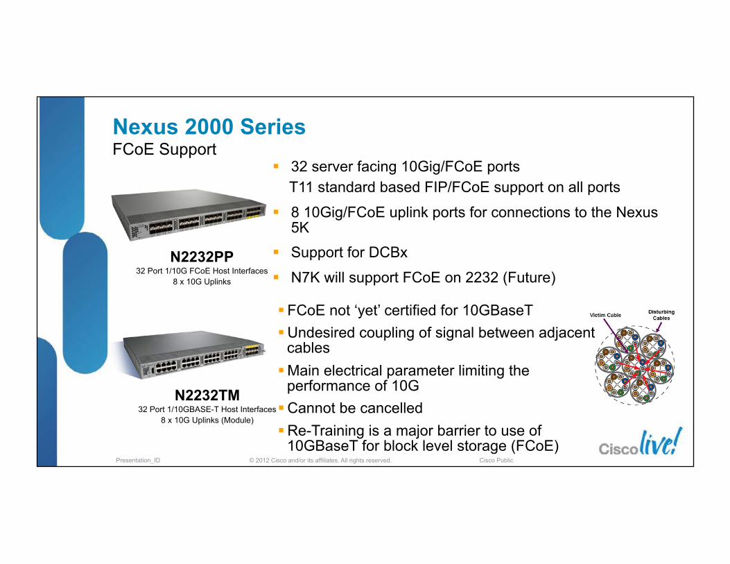
§ 32 server facing 10Gig/FCoE ports T11 standard based FIP/FCoE support on all ports
§ 8 10Gig/FCoE uplink ports for connections to the Nexus 5K
§ Support for DCBx
§ N7K will support FCoE on 2232 (Future)
Nexus 2000 Series FCoE Support
N2232TM 32 Port 1/10GBASE-T Host Interfaces
8 x 10G Uplinks (Module)
N2232PP 32 Port 1/10G FCoE Host Interfaces
8 x 10G Uplinks
§ FCoE not ‘yet’ certified for 10GBaseT § Undesired coupling of signal between adjacent
cables § Main electrical parameter limiting the
performance of 10G § Cannot be cancelled § Re-Training is a major barrier to use of
10GBaseT for block level storage (FCoE)

© 2012 Cisco and/or its affiliates. All rights reserved. Presentation_ID Cisco Public
Nexus 5500 + B22 (HP FEX)
B22 extends FEX connectivity into the HP blade chassis
Cisco Nexus 5000 Switch is a single management point for all the blade chassis I/O modules
66% decrease in blade management points*
Blade & rack networking consistency
Interoperable with Nexus 2000 Fabric Extenders in the same Nexus parent switch
End-to-end FCoE support
Support for 1G & 10G, LOM and Mez
Dell supports Pass-Thru as an alternative option to directly attaching Blade Servers to FEX ports
Cisco Nexus B22 Series Blade FEX
DC Design Details – Blade ChassisNexus B22 Series Fabric Extender

© 2012 Cisco and/or its affiliates. All rights reserved. Presentation_ID Cisco Public
Nexus 7000 F-Series SFP+ Module FCoE Support Q2CY11 § 32 & 48 port 1/10 GbE for Server Access and Aggregation
§ F1 Supports FCoE
§ F2 support for FCoE targeted 1HCY12 ‒ FEX + FCoE support – 2HCY12
§ 10 Gbps Ethernet supporting Multiprotocol Storage Connectivity § Supports FCoE, iSCSI and NAS
§ Loss-Less Ethernet: DCBX, PFC, ETS
§ Enables Cisco FabricPath for increased bisectional bandwidth for iSCSI and NAS traffic
§ FCoE License (N7K-FCOEF132XP) § $10,000 Cisco List
§ One license per F1/F2 module
§ SAN Enterprise (N7K-SAN1K9) § $15,000 Cisco List – per chassis
§ IVR, VSAN Based Access Control, Fabric Binding
32-‐port F1 Series
48-‐port F2 Series

© 2012 Cisco and/or its affiliates. All rights reserved. Presentation_ID Cisco Public
Storage VDC LAN VDC
FCoE & FIP
Ethernet
Dedicated for VE_Ports
Storage VDC on the Nexus 7000 Supported VDC models
Model for host/target interfaces, not VE_Port
Ingress Ethernet traffic is split based on frame ether type
FCoE traffic is processed in the context of the Storage VDC
Storage VDC LAN VDC
Converged I/O
FCoE & FIP Ethernet
§ Separate VDC running ONLY storage related protocols
§ Storage VDC: a virtual MDS FC switch
§ Running only FC related processes
§ Only one such VDC can be created
§ Provides control plane separation
Shared Converged Port

© 2012 Cisco and/or its affiliates. All rights reserved. Presentation_ID Cisco Public
Creating the Storage VDC § Create VDC of type storage and allocate non-‐shared interfaces: N7K-‐50(config)# vdc fcoe id 2 type storage N7K-‐50(config-‐vdc)# allocate interface Ethernet4/1-‐16, Ethernet4/19-‐22 § Allocate FCoE vlan range from the Owner VDC to the Storage VDC. This is a necessary step for sharing
interfaces to avoid vlan overlap between the Owner VDC and the Storage VDC
N7K-‐50(config) vdc fcoe id 2 N7K-‐50(config-‐vdc)# allocate fcoe-‐vlan-‐range 10-‐100 from vdcs n7k-‐50
§ Allocated the shared interfaces:
N7K-‐50(config-‐vdc)# allocate shared interface Ethernet4/17-‐18
§ Install the license for the FCoE Module.
n7k-‐50(config)# license fcoe module 4
N7K only

© 2012 Cisco and/or its affiliates. All rights reserved. Presentation_ID Cisco Public
F2 VDC
Storage VDC
F1/M1 VDC
F1 F2 F2 Any non-‐F2
Dedicated Ports
Storage VDC
F1/M1 VDC
F1
Storage VDC
F2 VDC
F2
NX-OS 5.2
NX-OS 6.1 (1HCY12)
NX-OS 6.1 (1HCY12)
Shared Ports
§ Some restric�ons when using mixed line cards (F1/F2/M1) § F2 ports need to be in a dedicated VDC if using ‘shared ports’
Storage VDC F2 line cards

© 2012 Cisco and/or its affiliates. All rights reserved. Presentation_ID Cisco Public
MDS 9000 8-Port 10G FCoE Module FCoE Support
§ Enables integra�on of exis�ng FC infrastructure into Unified Fabric
§ 8 FCoE ports at 10GE full rate in MDS 9506, 9509, 9513
§ No FCoE License Required
§ Standard Support
§ T11 FCoE
§ IEEE DCBX, PFC, ETS
§ Connec�vity – FCoE Only, No LAN
§ VE to Nexus 5000, Nexus 7000, MDS 9500
§ VF to FCoE Targets
§ Op�cs Support
§ SFP+ SR/LR, SFP+ 1/3/5m Passive, 7/10m Ac�ve CX-‐1 (TwinAx)
§ Requirements
§ SUP2A
§ Fabric 2 modules for the backplane (applicable to 9513 only)
MDS 9500

© 2012 Cisco and/or its affiliates. All rights reserved. Presentation_ID Cisco Public
Install feature-set fcoe feature-set fcoe
There is no need to enable FCoE explicitly on the MDS switch. The following features will be enabled once an FCoE capable linecard is detected.
Create VSAN and VLAN, Map VLAN to VSAN for FCoE pod3-9513-71(config)# vsan database pod3-9513-71(config-vsan-db)# vsan 50 pod3-9513-71(config-vsan-db)# vlan 50 pod3-9513-71(config-vlan)# fcoe vsan 50
Build the LACP Port Channel on the MDS Create VE port and assign to the LACP Port-channel pod3-9513-71(config-if-range)# interface vfc-port-channel 501 pod3-9513-71(config-if)# switchport mode e pod3-9513-71(config-if)# switchport trunk allowed vsan 50 pod3-9513-71(config-if)# no shut
feature lldp feature vlan-vsan-mapping
MDS 9000 8-Port 10G FCoE Module FCoE Support

© 2012 Cisco and/or its affiliates. All rights reserved. Presentation_ID Cisco Public
FCoE - Design, Operations and Management Best Practices Agenda
§ Unified Fabric – What and When § FCoE Protocol Fundamentals § Nexus FCoE Capabilities
§ FCoE Network Requirements and Design Considerations
§ DCB & QoS - Ethernet Enhancements § Single Hop Design § Multi-Hop Design
§ Futures
1K Cisco Nexus
x86

© 2012 Cisco and/or its affiliates. All rights reserved. Presentation_ID Cisco Public
Network vs. Fabric Differences & Similarities § Ethernet is non-deterministic.
‒ Flow control is destination-based ‒ Relies on TCP drop-retransmission / sliding window
§ Fibre-Channel is deterministic. ‒ Flow control is source-based (B2B credits) ‒ Services are fabric integrated (no loop concept) Channels
Connec�on service Physical circuits Reliable transfers High speed Low latency Short distance Hardware intense
Networks Connec�onless Logical circuits Unreliable transfers High connec�vity Higher latency Longer distance So�ware intense

© 2012 Cisco and/or its affiliates. All rights reserved. Presentation_ID Cisco Public
§ Ethernet/IP
‒ Goal : provide any-to-any connectivity
‒ Unaware of packet loss (“lossy”) – relies on ULPs for retransmission and windowing
‒ Provides the transport without worrying about the services - services provided by upper layers
‒ East-west vs north-south traffic ratios are undefined
§ Network design has been optimized for: ‒ High Availability from a transport perspective by connecting nodes in mesh architectures
‒ Service HA is implemented separately
‒ Takes in to account control protocol interaction (STP, OSPF, EIGRP, L2/L3 boundary, etc…)
? ?
?
?
? ? ? ?
?
?
? ?
Switch Switch
Switch
?
Client/Server Relationships are not pre-
defined
? ?
?
Fabric topology and traffic flows are highly flexible
Network vs. Fabric Classical Ethernet

© 2012 Cisco and/or its affiliates. All rights reserved. Presentation_ID Cisco Public
§ Servers typically dual homed to two or more access switches
§ LAN switches have redundant connections to the next layer
§ Distribution and Core can be collapsed into a single box
§ L2/L3 boundary typically deployed in the aggregation layer ‒ Spanning tree or advanced L2 technologies (vPC) used to prevent loops within the L2 boundary ‒ L3 routes are summarized to the core
§ Services deployed in the L2/L3 boundary of the network (load-balancing, firewall, NAM, etc)
L2
L3
Core
Aggrega�on
Access
Virtual Port-‐Channel (VPC)
Virtual Port-‐Channel (VPC)
Outside Data Center “cloud”
STP
STP
Network vs. Fabric LAN Design – Access/Aggrega�on/Core

© 2012 Cisco and/or its affiliates. All rights reserved. Presentation_ID Cisco Public
§ Fibre Channel SAN ‒ Transport and Services are on the same layer in the same devices
‒ Well defined end device relationships (initiators and targets)
‒ Does not tolerate packet drop – requires lossless transport
‒ Only north-south traffic, east-west traffic mostly irrelevant
§ Network designs optimized for Scale and Availability
‒ High availability of network services provided through dual fabric architecture
‒ Edge/Core vs Edge/Core/Edge
‒ Service deployment Client/Server Relationships
are pre-defined
I(c)
I(c) T(s)
Fabric topology, services and traffic flows are structured
Network vs. Fabric Classical Fibre Channel
T2
I5
I4 I3 I2
I1 I0
T1 T0
Switch Switch
Switch
DNS FSPF
Zone RSCN DNS
FSPF Zone
RSCN
DNS
Zone
FSPF
RSCN

© 2012 Cisco and/or its affiliates. All rights reserved. Presentation_ID Cisco Public
§ “Edge-Core” or “Edge-Core-Edge” Topology § Servers connect to the edge switches § Storage devices connect to one or more core
switches § HA achieved in two physically separate, but
identical, redundant SAN fabric § Very low oversubscription in the fabric (1:1 to
12:1)
§ FLOGI Scaling Considerations
FC
Core Core
Network vs. Fabric SAN Design – Two ‘or’ Three Tier Topology
FC
Example: 10:1 O/S ra�o
60 Servers with 4 Gb HBAs
240 G 24 G 24 G

© 2012 Cisco and/or its affiliates. All rights reserved. Presentation_ID Cisco Public
FC FCoE
AGG
Access
CORE
L3
L2
§ Converged Link to the access switch
§ Cost savings in the reduction of required equipment
§ “cable once” for all servers to have access to both LAN and SAN networks
§ Dedicated Link from access to aggregation
§ Separate links for SAN and LAN traffic - both links are same I/O (10GE)
§ Advanced Ethernet features can be applied to the LAN links
§ Maintains fabric isolation
Dedicated FCoE Links/Port-Channels
MDS FC SAN A
MDS FC SAN B
Ethernet Fibre Channel Dedicated FCoE Link Converged Link
Converged FCoE Link
Nexus
Converged FCoE Link
vPC Port Channel
Port Channel
Network vs. Fabric Converged and Dedicated Links
© 2012 Cisco and/or its affiliates. All rights reserved. Presentation_ID Cisco Public
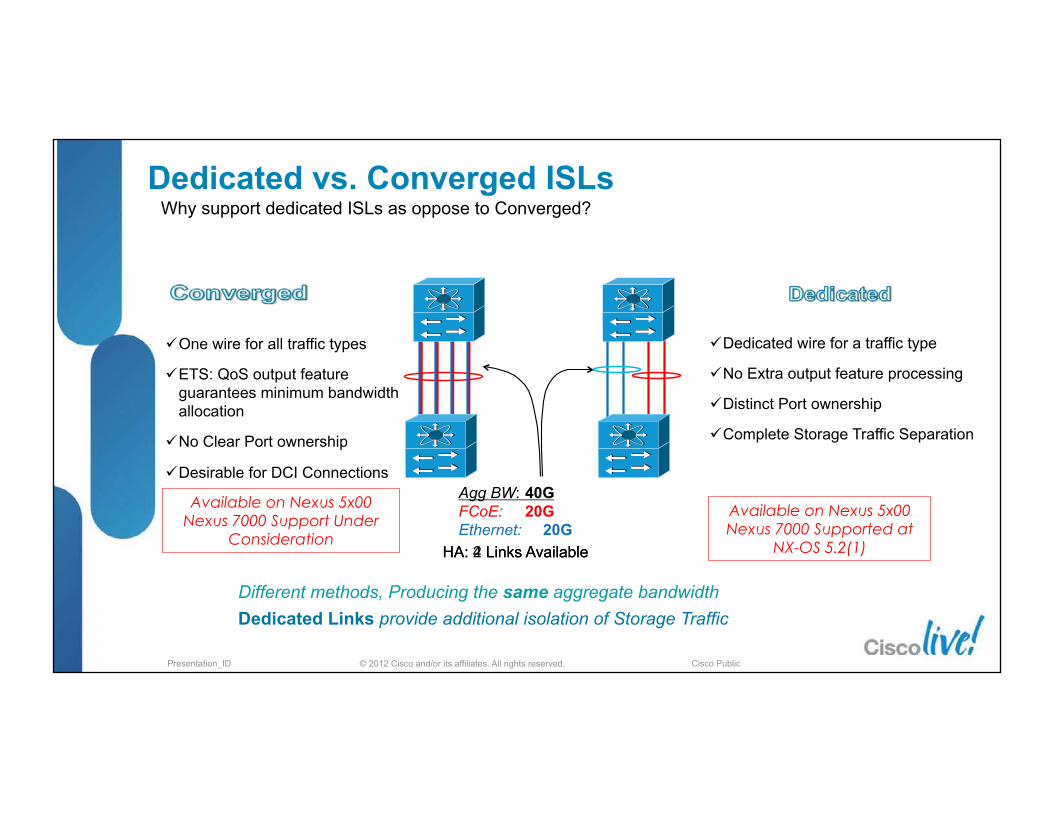
Why support dedicated ISLs as oppose to Converged?
Agg BW: 40G FCoE: 20G Ethernet: 20G
ü One wire for all traffic types
ü ETS: QoS output feature guarantees minimum bandwidth allocation
ü No Clear Port ownership
ü Desirable for DCI Connections
ü Dedicated wire for a traffic type
ü No Extra output feature processing
ü Distinct Port ownership
ü Complete Storage Traffic Separation
Different methods, Producing the same aggregate bandwidth Dedicated Links provide additional isolation of Storage Traffic
Available on Nexus 5x00 Nexus 7000 Supported at
NX-OS 5.2(1)
Available on Nexus 5x00 Nexus 7000 Support Under
Consideration HA: 4 Links Available HA: 2 Links Available
Dedicated vs. Converged ISLs

© 2012 Cisco and/or its affiliates. All rights reserved. Presentation_ID Cisco Public
Shared wire and VPC – does it break basic SAN design fundamentals?
FCoE
Fabric A
Fabric B
vPC with Converged Links provides an Active-Active connection for FCoE traffic Seemingly more bandwidth to the Core… Ethernet forwarding behavior can break SAN A/B separation
Currently Not supported on Nexus Switches (exception is the dual homed FEX - EVPC)
B
Now that I have Converged Link Support. Can I deploy vPC for my Storage Traffic?
Converged Links and vPC

© 2012 Cisco and/or its affiliates. All rights reserved. Presentation_ID Cisco Public
FC
Core Core
“Fabric vs. Network” or “Fabric & Network” SAN Dual Fabric Design
FC
FC
?
§ Will you migrate the SAN dual fabric HA model into the LAN full meshed HA model
§ Is data plane isola�on required? (traffic engineering)
§ Is control plane isola�on required? (VDC, VSAN)

© 2012 Cisco and/or its affiliates. All rights reserved. Presentation_ID Cisco Public
“Fabric vs. Network” or “Fabric & Network” Hop by Hop or Transparent Forwarding Model
‘or’
§ A number of big design questions for you
§ Do you want a ‘routed’ topology or a ‘bridged’ topology
§ Is FCoE a layer 2 overlay or integrated topology (ships in the night)
VE VF VE VF VE VE VN VN
VF VN VF VN VE VE

© 2012 Cisco and/or its affiliates. All rights reserved. Presentation_ID Cisco Public
H1
H2
H3
Traffic
QCN message
QCN message
DA: H3 SA: H1
DA: H3 SA: H2
DA: H1 SA: H3
DA: H2 SA: H3
Hop by Hop or Transparent Forwarding Model 802.1Qau Congestion Notification - QCN
QCN/DCB
Congestion
§ Self-Clocking Control loop
§ Derived from FCC (Fibre Channel Congestion Control)
§ Congestion Control between layer 2 devices
§ Not passed through any device that changes MAC addresses

© 2012 Cisco and/or its affiliates. All rights reserved. Presentation_ID Cisco Public
FCoE - Design, Operations and Management Best Practices Agenda
§ Unified Fabric – What and When § FCoE Protocol Fundamentals § Nexus FCoE Capabilities
§ FCoE Network Requirements and Design Considerations
§ DCB & QoS - Ethernet Enhancements § Single Hop Design § Multi-Hop Design
§ Futures
1K Cisco Nexus
x86

© 2012 Cisco and/or its affiliates. All rights reserved. Presentation_ID Cisco Public
Ethernet Enhancements Can Ethernet Be Lossless?
§ Yes, with Ethernet PAUSE Frame
PAUSE STOP
Ethernet Link
Switch A Switch B
Queue Full
§ Defined in IEEE 802.3—Annex 31B
§ The PAUSE opera�on is used to inhibit transmission of data frames for a specified period of �me
§ Ethernet PAUSE transforms Ethernet into a lossless fabric, a requirement for FCoE

© 2012 Cisco and/or its affiliates. All rights reserved. Presentation_ID Cisco Public
Ethernet Enhancements IEEE DCB
Standard / Feature Status of the Standard IEEE 802.1Qbb Priority-based Flow Control (PFC) Completed
IEEE 802.3bd Frame Format for PFC Completed
IEEE 802.1Qaz Enhanced Transmission Selection (ETS) and Data Center Bridging eXchange (DCBX)
Completed
IEEE 802.1Qau Congestion Notification Complete, published March 2010 IEEE 802.1Qbh Port Extender In its first task group ballot
§ Developed by IEEE 802.1 Data Center Bridging Task Group (DCB) § All Standards Complete
CEE (Converged Enhanced Ethernet) is an informal group of companies that submi�ed ini�al inputs to the DCB WGs.

© 2012 Cisco and/or its affiliates. All rights reserved. Presentation_ID Cisco Public
Ethernet Enhancements DCB “Virtual Links”
VL1 VL2 VL3
LAN/IP Gateway
VL1 – LAN Service – LAN/IP VL2 -‐ No Drop Service -‐ Storage
Ability to support different forwarding behaviours, e.g. QoS, MTU, … queues within the “lanes”
Campus Core/ Internet
Storage Area Network
© 2012 Cisco and/or its affiliates. All rights reserved. Presentation_ID Cisco Public
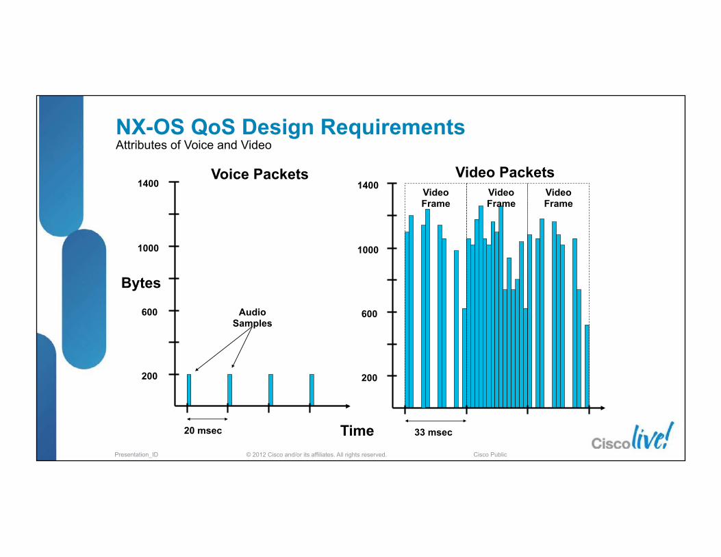
20 msec
Voice Packets
Bytes
200
600
1000
Audio Samples
1400
Time
200
600
1000
1400
33 msec
Video Packets Video Frame
Video Frame
Video Frame
NX-OS QoS Design Requirements Attributes of Voice and Video
© 2012 Cisco and/or its affiliates. All rights reserved. Presentation_ID Cisco Public
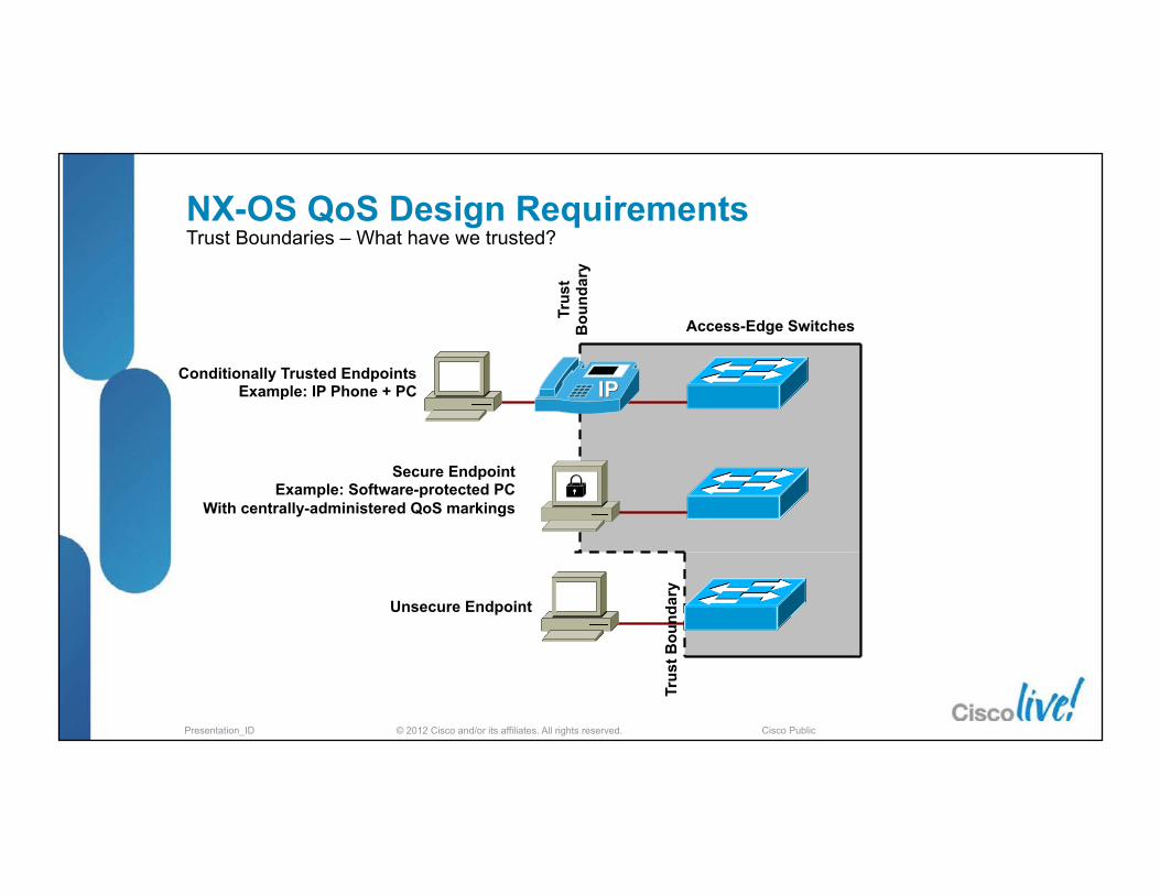
Access-Edge Switches
Conditionally Trusted Endpoints Example: IP Phone + PC
Secure Endpoint Example: Software-protected PC
With centrally-administered QoS markings
Unsecure Endpoint
Trus
t Bou
ndar
y
Trus
t B
ound
ary
NX-OS QoS Design Requirements Trust Boundaries – What have we trusted?

© 2012 Cisco and/or its affiliates. All rights reserved. Presentation_ID Cisco Public
PCP/COS Network priority Acronym Traffic characteristics
1 0 (lowest) BK Background
0 1 BE Best Effort
2 2 EE Excellent Effort
3 3 CA Critical Applications
4 4 VI Video, < 100 ms latency
5 5 VO Voice, < 10 ms latency
6 6 IC Internetwork Control
IEEE 802.1Q-‐2005
NX-OS QoS Requirements CoS or DSCP?
§ We have non IP based traffic to consider again FCoE – Fibre Channel Over Ethernet
RCoE – RDMA Over Ethernet
§ DSCP is still marked but CoS will be required and used in Nexus Data Center designs

© 2012 Cisco and/or its affiliates. All rights reserved. Presentation_ID Cisco Public
Data Center Bridging Control Protocol DCBX Overview - 802.1Qaz
DCBX Switch
DCBX CNA Adapter
§ Negotiates Ethernet capability’s : PFC, ETS, CoS values between DCB capable peer devices
§ Simplifies Management : allows for configuration and distribution of parameters from one node to another
§ Responsible for Logical Link Up/Down signaling of Ethernet and Fibre Channel
§ DCBX is LLDP with new TLV fields § The original pre-standard CIN (Cisco, Intel, Nuova) DCBX utilized
additional TLV’s § DCBX negotiation failures result in:
§ per-priority-pause not enabled on CoS values § vfc not coming up – when DCBX is being used in FCoE
environment dc11-5020-3# sh lldp dcbx interface eth 1/40 Local DCBXP Control information: Operation version: 00 Max version: 00 Seq no: 7 Ack no: 0 Type/ Subtype Version En/Will/Adv Config 006/000 000 Y/N/Y 00 <snip>
https://www.cisco.com/en/US/netsol/ns783/index.html

© 2012 Cisco and/or its affiliates. All rights reserved. Presentation_ID Cisco Public
Packet
R_R
DY
Fibre Channel Transmit Queues Ethernet Link Receive Buffers
Eight Virtual Lanes
One One
Two Two
Three Three
Four Four
Five Five
Seven Seven
Eight Eight
Six Six
STOP PAUSE
B2B Credits
§ Enables lossless Ethernet using PAUSE based on a COS as defined in 802.1p § When link is congested, CoS assigned to “no-drop” will be PAUSED § Other traffic assigned to other CoS values will continue to transmit and rely on upper
layer protocols for retransmission § Not only for FCoE traffic
Priority Flow Control FCoE Flow Control Mechanism – 802.1Qbb

© 2012 Cisco and/or its affiliates. All rights reserved. Presentation_ID Cisco Public
Offered Traffic
t1 t2 t3
10 GE Link Realized Traffic Utilization
3G/s HPC Traffic 3G/s
2G/s
3G/s Storage Traffic 3G/s
3G/s
LAN Traffic 4G/s
5G/s 3G/s
t1 t2 t3
3G/s 3G/s
3G/s 3G/s 3G/s
2G/s
3G/s 4G/s 6G/s
§ Prevents a single traffic class of “hogging” all the bandwidth and starving other classes
§ When a given load doesn’t fully utilize its allocated bandwidth, it is available to other classes
§ Helps accommodate for classes of a “bursty” nature
Enhanced Transmission Selection (ETS) Bandwidth Management – 802.1Qaz

© 2012 Cisco and/or its affiliates. All rights reserved. Presentation_ID Cisco Public
Nexus QoS QoS Policy Types § There are three QoS policy types used to define system
behavior (qos, queuing, network-‐qos) § There are three policy a�achment points to apply these
policies to § Ingress interface
§ System as a whole (defines global behavior) § Egress interface
Policy Type Function Attach Point
qos Define traffic classification rules system qos ingress Interface
queuing Strict Priority queue Deficit Weight Round Robin
system qos egress Interface ingress Interface
network-qos System class characteristics (drop or no-drop, MTU), Buffer size, Marking system qos
© 2012 Cisco and/or its affiliates. All rights reserved. Presentation_ID Cisco Public
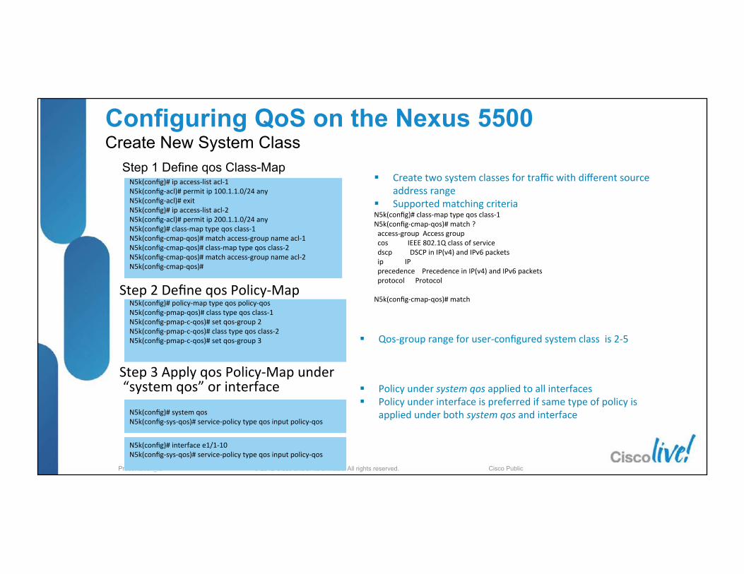
Configuring QoS on the Nexus 5500 Create New System Class
Step 1 Define qos Class-Map
Step 2 Define qos Policy-‐Map
Step 3 Apply qos Policy-‐Map under “system qos” or interface
N5k(config)# ip access-‐list acl-‐1 N5k(config-‐acl)# permit ip 100.1.1.0/24 any N5k(config-‐acl)# exit N5k(config)# ip access-‐list acl-‐2 N5k(config-‐acl)# permit ip 200.1.1.0/24 any N5k(config)# class-‐map type qos class-‐1 N5k(config-‐cmap-‐qos)# match access-‐group name acl-‐1 N5k(config-‐cmap-‐qos)# class-‐map type qos class-‐2 N5k(config-‐cmap-‐qos)# match access-‐group name acl-‐2 N5k(config-‐cmap-‐qos)#
N5k(config)# policy-‐map type qos policy-‐qos N5k(config-‐pmap-‐qos)# class type qos class-‐1 N5k(config-‐pmap-‐c-‐qos)# set qos-‐group 2 N5k(config-‐pmap-‐c-‐qos)# class type qos class-‐2 N5k(config-‐pmap-‐c-‐qos)# set qos-‐group 3
N5k(config)# system qos N5k(config-‐sys-‐qos)# service-‐policy type qos input policy-‐qos
N5k(config)# interface e1/1-‐10 N5k(config-‐sys-‐qos)# service-‐policy type qos input policy-‐qos
§ Create two system classes for traffic with different source address range
§ Supported matching criteria N5k(config)# class-‐map type qos class-‐1 N5k(config-‐cmap-‐qos)# match ? access-‐group Access group cos IEEE 802.1Q class of service dscp DSCP in IP(v4) and IPv6 packets ip IP precedence Precedence in IP(v4) and IPv6 packets protocol Protocol N5k(config-‐cmap-‐qos)# match
§ Qos-‐group range for user-‐configured system class is 2-‐5
§ Policy under system qos applied to all interfaces § Policy under interface is preferred if same type of policy is
applied under both system qos and interface

© 2012 Cisco and/or its affiliates. All rights reserved. Presentation_ID Cisco Public
Configuring QoS on the Nexus 5500 Create New System Class(Continue) Step 4 Define network-qos Class-Map
Step 5 Define network-‐qos Policy-‐Map
Step 6 Apply network-‐qos policy-‐map under system qos context
N5k(config)# class-‐map type network-‐qos class-‐1 N5k(config-‐cmap-‐nq)# match qos-‐group 2 N5k(config-‐cmap-‐nq)# class-‐map type network-‐qos class-‐2 N5k(config-‐cmap-‐nq)# match qos-‐group 3
N5k(config)# policy-‐map type network-‐qos policy-‐nq N5k(config-‐pmap-‐nq)# class type network-‐qos class-‐1 N5k(config-‐pmap-‐nq-‐c)# class type network-‐qos class-‐2
N5k(config-‐pmap-‐nq-‐c)# system qos N5k(config-‐sys-‐qos)# service-‐policy type network-‐qos policy-‐nq N5k(config-‐sys-‐qos)#
§ No ac�on �ed to this class indicates default network-‐qos parameters.
§ Policy-‐map type network-‐qos will be used to configure no-‐drop class, MTU, ingress buffer size and 802.1p marking
§ Default network-‐qos parameters are listed in the table below
Network-QoS Parameters
Default Value
Class Type Drop class MTU 1538
Ingress Buffer Size 20.4KB Marking No marking
§ Match qos-‐group is the only op�on for network-‐qos class-‐map
§ Qos-‐group value is set by qos policy-‐map in previous slide

© 2012 Cisco and/or its affiliates. All rights reserved. Presentation_ID Cisco Public
Configuring QoS on the Nexus 5500 Strict Priority and Bandwidth Sharing
§ Create new system class by using policy-‐map qos and network-‐qos(Previous two slides)
§ Then Define and apply policy-‐map type queuing to configure strict priority and bandwidth sharing
§ Checking the queuing or bandwidth alloca�ng with command show queuing interface N5k(config)# class-‐map type queuing class-‐1 N5k(config-‐cmap-‐que)# match qos-‐group 2 N5k(config-‐cmap-‐que)# class-‐map type queuing class-‐2 N5k(config-‐cmap-‐que)# match qos-‐group 3 N5k(config-‐cmap-‐que)# exit N5k(config)# policy-‐map type queuing policy-‐BW N5k(config-‐pmap-‐que)# class type queuing class-‐1 N5k(config-‐pmap-‐c-‐que)# priority N5k(config-‐pmap-‐c-‐que)# class type queuing class-‐2 N5k(config-‐pmap-‐c-‐que)# bandwidth percent 40 N5k(config-‐pmap-‐c-‐que)# class type queuing class-‐fcoe N5k(config-‐pmap-‐c-‐que)# bandwidth percent 40 N5k(config-‐pmap-‐c-‐que)# class type queuing class-‐default N5k(config-‐pmap-‐c-‐que)# bandwidth percent 20 N5k(config-‐pmap-‐c-‐que)# system qos N5k(config-‐sys-‐qos)# service-‐policy type queuing output policy-‐BW N5k(config-‐sys-‐qos)#
Define queuing class-‐map
Define queuing policy-‐map
Apply queuing policy under system qos or egress interface

© 2012 Cisco and/or its affiliates. All rights reserved. Presentation_ID Cisco Public
Configuring QoS on the Nexus 5500 Check System Classes
N5k# show queuing interface ethernet 1/1 Interface Ethernet1/1 TX Queuing qos-‐group sched-‐type oper-‐bandwidth 0 WRR 20 1 WRR 40 2 priority 0 3 WRR 40 Interface Ethernet1/1 RX Queuing qos-‐group 0: q-‐size: 163840, MTU: 1538 drop-‐type: drop, xon: 0, xoff: 1024 Sta�s�cs: Pkts received over the port : 9802 Ucast pkts sent to the cross-‐bar : 0 Mcast pkts sent to the cross-‐bar : 9802 Ucast pkts received from the cross-‐bar : 0 Pkts sent to the port : 18558 Pkts discarded on ingress : 0 Per-‐priority-‐pause status : Rx (Inac�ve), Tx (Inac�ve) qos-‐group 1: q-‐size: 76800, MTU: 2240 drop-‐type: no-‐drop, xon: 128, xoff: 240 Sta�s�cs: Pkts received over the port : 0 Ucast pkts sent to the cross-‐bar : 0 Mcast pkts sent to the cross-‐bar : 0 Ucast pkts received from the cross-‐bar : 0 Pkts sent to the port : 0 Pkts discarded on ingress : 0 Per-‐priority-‐pause status : Rx (Inac�ve), Tx (Inac�ve) Con�nue…
qos-‐group 2: q-‐size: 20480, MTU: 1538 drop-‐type: drop, xon: 0, xoff: 128 Sta�s�cs: Pkts received over the port : 0 Ucast pkts sent to the cross-‐bar : 0 Mcast pkts sent to the cross-‐bar : 0 Ucast pkts received from the cross-‐bar : 0 Pkts sent to the port : 0 Pkts discarded on ingress : 0 Per-‐priority-‐pause status : Rx (Inac�ve), Tx (Inac�ve) qos-‐group 3: q-‐size: 20480, MTU: 1538 drop-‐type: drop, xon: 0, xoff: 128 Sta�s�cs: Pkts received over the port : 0 Ucast pkts sent to the cross-‐bar : 0 Mcast pkts sent to the cross-‐bar : 0 Ucast pkts received from the cross-‐bar : 0 Pkts sent to the port : 0 Pkts discarded on ingress : 0 Per-‐priority-‐pause status : Rx (Inac�ve), Tx (Inac�ve) Total Mul�cast crossbar sta�s�cs: Mcast pkts received from the cross-‐bar : 18558 N5k#
Strict priority and WRR configura�on
class-‐default
class-‐fcoe
User-‐configured system class: class-‐1
User-‐configured system class: class-‐2
Packet counter for each class
Drop counter for each class
Current PFC status

© 2012 Cisco and/or its affiliates. All rights reserved. Presentation_ID Cisco Public
§ On Nexus 5000 once feature fcoe is configured, 2 classes are made by default
Priority Flow Control – Nexus 5000/5500 Operations Configuration – Switch Level
FCoE DCB Switch
DCB CNA Adapter
§ class-fcoe is configured to be no-drop with an MTU of 2158
policy-map type qos default-in-policy class type qos class-fcoe set qos-group 1 class type qos class-default set qos-group 0
policy-map type network-qos default-nq-policy class type network-qos class-fcoe pause no-drop mtu 2158
system qos service-policy type qos input fcoe-default-in-policy service-policy type queuing input fcoe-default-in-policy service-policy type queuing output fcoe-default-out-policy service-policy type network-qos fcoe-default-nq-policy
§ Enabling the FCoE feature on Nexus 5548/96 does ‘not’ create no-drop policies automatically as on Nexus 5010/20
§ Must add policies under system QOS:

© 2012 Cisco and/or its affiliates. All rights reserved. Presentation_ID Cisco Public
Configs for 3000m no-drop
class Buffer size Pause Threshold
(XOFF) Resume
Threshold (XON)
N5020 143680 bytes 58860 bytes 38400 bytes
N5548 152000 bytes 103360 bytes 83520 bytes
§ Tuning of the lossless queues to support a variety of use cases § Extended switch to switch no drop traffic lanes
§ Support for 3km with Nexus 5000 and 5500 § Increased number of no drop services lanes (4) for RDMA
and other multi-queue HPC and compute applications
Support for 3 km no drop switch to
switch links Inter Building DCB
FCoE links
Nexus 5000/5500 QoS Priority Flow Control and No-Drop Queues
5548-FCoE(config)# policy-map type network-qos 3km-FCoE 5548-FCoE(config-pmap-nq)# class type network-qos 3km-FCoE 5548-FCoE(config-pmap-nq-c)# pause no-drop buffer-size 152000 pause-threshold 103360 resume-threshold 83520
Gen 2 UPC
Unified Crossbar Fabric
Gen 2 UPC

© 2012 Cisco and/or its affiliates. All rights reserved. Presentation_ID Cisco Public
Enhanced Transmission Selection - N5K Bandwidth Management
§ When configuring FCoE by default, each class is given 50% of the available bandwidth
§ Can be changed through QoS settings when higher demands for certain traffic exist (i.e. HPC traffic, more Ethernet NICs)
1Gig FC HBAs
1Gig Ethernet NICs
Traditional Server
§ Best Practice: Tune FCoE queue to provide equivalent capacity to the HBA that would have been used (1G, 2G, …)
N5k-1# show queuing interface ethernet 1/18 Ethernet1/18 queuing information: TX Queuing qos-group sched-type oper-bandwidth 0 WRR 50 1 WRR 50

© 2012 Cisco and/or its affiliates. All rights reserved. Presentation_ID Cisco Public
show policy-map system Type network-qos policy-maps ===================================== policy-map type network-qos default-nq-7e-policy class type network-qos c-nq-7e-drop match cos 0-2,4-7 congestion-control tail-drop mtu 1500 class type network-qos c-nq-7e-ndrop-fcoe match cos 3 match protocol fcoe pause mtu 2112
Priority Flow Control – Nexus 7K & MDS Operations Configuration – Switch Level
N7K-50(config)# system qos
N7K-50(config-sys-qos)# service-policy type network-qos default-nq-7e-policy
Policy Template choices
§ No-Drop PFC w/ MTU 2K set for Fibre Channel show class-map type network-qos c-nq-7e-ndrop-fcoe Type network-qos class-maps ============================================= class-map type network-qos match-any c-nq-7e-ndrop-fcoe Description: 7E No-Drop FCoE CoS map match cos 3 match protocol fcoe
Template Drop CoS (Priority) NoDrop CoS (Priority)
default-nq-8e-policy 0,1,2,3,4,5,6,7 5,6,7 - -
default-nq-7e-policy 0,1,2,4,5,6,7 5,6,7 3 -
default-nq-6e-policy 0,1,2,5,6,7 5,6,7 3,4 4
default-nq-4e-policy 0,5,6,7 5,6,7 1,2,3,4 4

© 2012 Cisco and/or its affiliates. All rights reserved. Presentation_ID Cisco Public
Nexus 7000 QoS queuing policies - 7e policy
n7k-‐50# sh policy-‐map type queuing default-‐4q-‐7e-‐in-‐policy policy-‐map type queuing default-‐4q-‐7e-‐in-‐policy class type queuing c-‐4q-‐7e-‐drop-‐in service-‐policy type queuing default-‐4q-‐7e-‐drop-‐in-‐policy queue-‐limit percent 70 class type queuing c-‐4q-‐7e-‐ndrop-‐in service-‐policy type queuing default-‐4q-‐7e-‐ndrop-‐in-‐policy queue-‐limit percent 30 n7k-‐50# sh policy-‐map type queuing default-‐4q-‐7e-‐drop-‐in-‐policy policy-‐map type queuing default-‐4q-‐7e-‐drop-‐in-‐policy class type queuing 4q4t-‐7e-‐in-‐q1 queue-‐limit percent 10 bandwidth percent 25 class type queuing 4q4t-‐7e-‐in-‐q-‐default queue-‐limit percent 45 bandwidth percent 25 class type queuing 4q4t-‐7e-‐in-‐q3 queue-‐limit percent 45 bandwidth percent 25 n7k-‐50# sh policy-‐map type queuing default-‐4q-‐7e-‐ndrop-‐in-‐policy policy-‐map type queuing default-‐4q-‐7e-‐ndrop-‐in-‐policy class type queuing 4q4t-‐7e-‐in-‐q4 queue-‐limit percent 100 bandwidth percent 25
class-‐map type queuing match-‐any 4q4t-‐7e-‐in-‐q-‐default match cos 0-‐1
class-‐map type queuing match-‐any 4q4t-‐7e-‐in-‐q4 match cos 3
class-‐map type queuing match-‐any 4q4t-‐7e-‐in-‐q3 match cos 2,4
class-‐map type queuing match-‐any 4q4t-‐7e-‐in-‐q1 match cos 5-‐7
FCoE
Bandwidth can be modified and passed to CNA via DCBx
© 2012 Cisco and/or its affiliates. All rights reserved. Presentation_ID Cisco Public
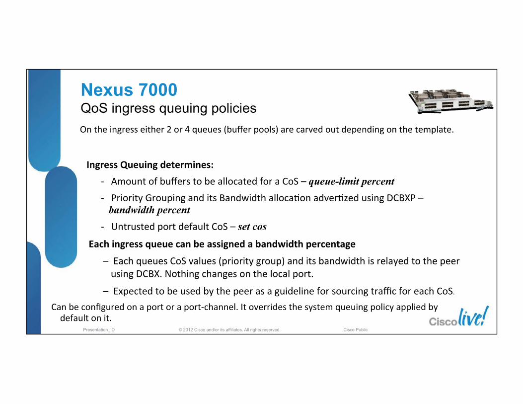
On the ingress either 2 or 4 queues (buffer pools) are carved out depending on the template.
Ingress Queuing determines: -‐ Amount of buffers to be allocated for a CoS – queue-limit percent -‐ Priority Grouping and its Bandwidth alloca�on adver�zed using DCBXP –
bandwidth percent -‐ Untrusted port default CoS – set cos
Each ingress queue can be assigned a bandwidth percentage
– Each queues CoS values (priority group) and its bandwidth is relayed to the peer using DCBX. Nothing changes on the local port.
– Expected to be used by the peer as a guideline for sourcing traffic for each CoS.
Can be configured on a port or a port-‐channel. It overrides the system queuing policy applied by default on it.
Nexus 7000 QoS ingress queuing policies
© 2012 Cisco and/or its affiliates. All rights reserved. Presentation_ID Cisco Public
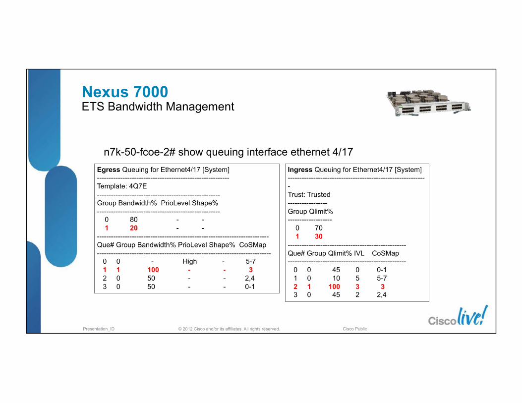
Ingress Queuing for Ethernet4/17 [System] ------------------------------------------------------------ Trust: Trusted ----------------- Group Qlimit% ------------------- 0 70 1 30 --------------------------------------------------- Que# Group Qlimit% IVL CoSMap --------------------------------------------------- 0 0 45 0 0-1 1 0 10 5 5-7 2 1 100 3 3 3 0 45 2 2,4
Egress Queuing for Ethernet4/17 [System] --------------------------------------------------------- Template: 4Q7E ----------------------------------------------------- Group Bandwidth% PrioLevel Shape% ----------------------------------------------------- 0 80 - - 1 20 - - -------------------------------------------------------------------------- Que# Group Bandwidth% PrioLevel Shape% CoSMap --------------------------------------------------------------------------- 0 0 - High - 5-7 1 1 100 - - 3 2 0 50 - - 2,4 3 0 50 - - 0-1
n7k-50-fcoe-2# show queuing interface ethernet 4/17
Nexus 7000 ETS Bandwidth Management

© 2012 Cisco and/or its affiliates. All rights reserved. Presentation_ID Cisco Public
MDS 9500 QoS - ETS
9513-‐71# sh policy-‐map interface ethernet 13/1 Global sta�s�cs status : enabled Ethernet 13/1 Service-‐policy (queuing) input: default-‐4q-‐7e-‐in-‐policy policy sta�s�cs status: enabled (current status: enabled) Class-‐map (queuing): 1q4t-‐7e-‐in-‐q-‐default (match-‐any) queue-‐limit percent 100 bandwidth percent 100 queue dropped pkts : 0 Service-‐policy (queuing) output: default-‐4q-‐7e-‐out-‐policy policy sta�s�cs status: enabled (current status: enabled) Class-‐map (queuing): 1q1t-‐7e-‐out-‐q-‐default (match-‐any) bandwidth remaining percent 100 queue dropped pkts : 0
9513-‐71# sh policy-‐map system type queuing Service-‐policy (queuing) input: default-‐4q-‐7e-‐in-‐policy policy sta�s�cs status: disabled (current status: disabled) Class-‐map (queuing): 1q4t-‐7e-‐in-‐q-‐default (match-‐any) queue-‐limit percent 100 bandwidth percent 100 Service-‐policy (queuing) output: default-‐4q-‐7e-‐out-‐policy policy sta�s�cs status: disabled (current status: disabled) Class-‐map (queuing): 1q1t-‐7e-‐out-‐q-‐default (match-‐any) bandwidth remaining percent 100
§ MDS FCoE linecard does not compete with the Fibre Channel bandwidth and received 100% of the ethernet bandwidth
© 2012 Cisco and/or its affiliates. All rights reserved. Presentation_ID Cisco Public
iSCSI
2G
1G 1G 1G 1G
1G
2G
4G
10G
10G
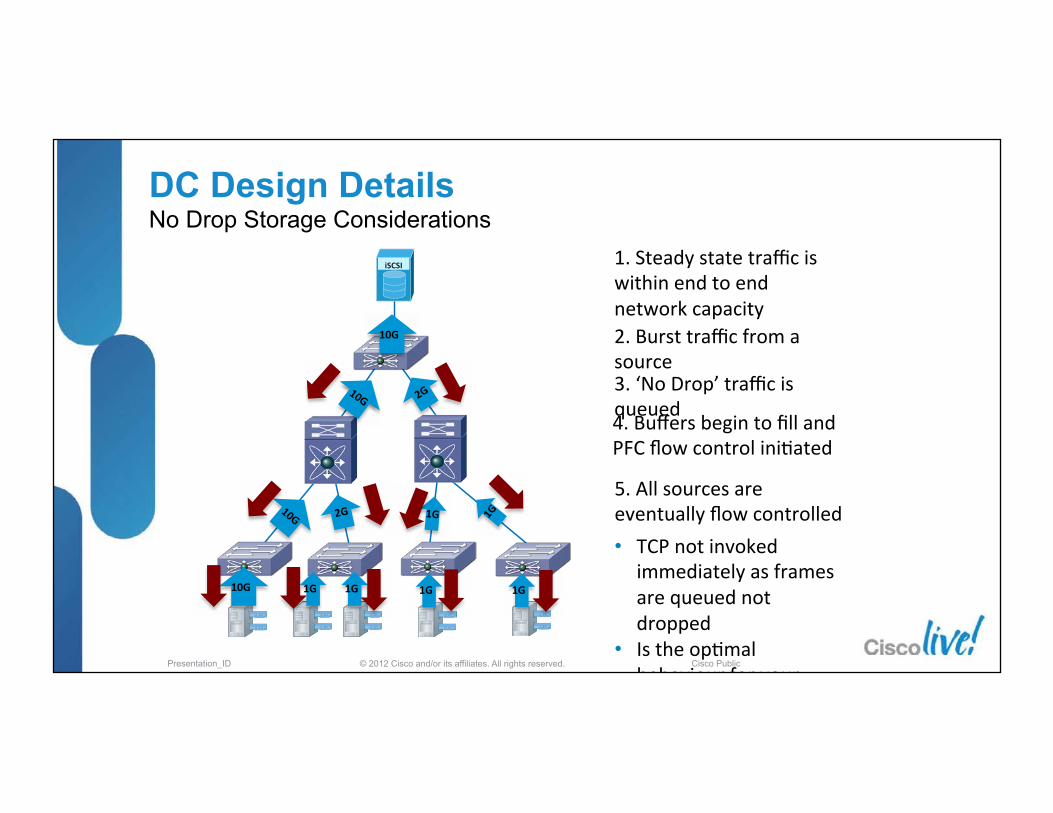
1. Steady state traffic is within end to end network capacity 2. Burst traffic from a source
5. All sources are eventually flow controlled
3. ‘No Drop’ traffic is queued
DC Design Details No Drop Storage Considerations
4. Buffers begin to fill and PFC flow control ini�ated
TCP not invoked immediately as frames are queued not dropped
Is the op�mal behaviour for your

© 2012 Cisco and/or its affiliates. All rights reserved. Presentation_ID Cisco Public
§ Blocking - Impact on Design Performance § Performance can be adversely affected across an entire multiswitch
FC Fabric by a single blocking port ‒ HOL is a transitory event (until some BB_Credits are returned on the blocked
port)
§ To help alleviate the blocking problem and enhance the design performance ‒ Virtual Output Queuing (VoQ) on all ports
DC Design Details HOLB is also a fundamental part of Fibre Channel SAN design

© 2012 Cisco and/or its affiliates. All rights reserved. Presentation_ID Cisco Public
FCoE - Design, Operations and Management Best Practices Agenda
§ Unified Fabric – What and When § FCoE Protocol Fundamentals § Nexus FCoE Capabilities
§ FCoE Network Requirements and Design Considerations
§ DCB & QoS - Ethernet Enhancements § Single Hop Design § Multi-Hop Design
§ Futures
1K Cisco Nexus
x86
© 2012 Cisco and/or its affiliates. All rights reserved. Presentation_ID Cisco Public
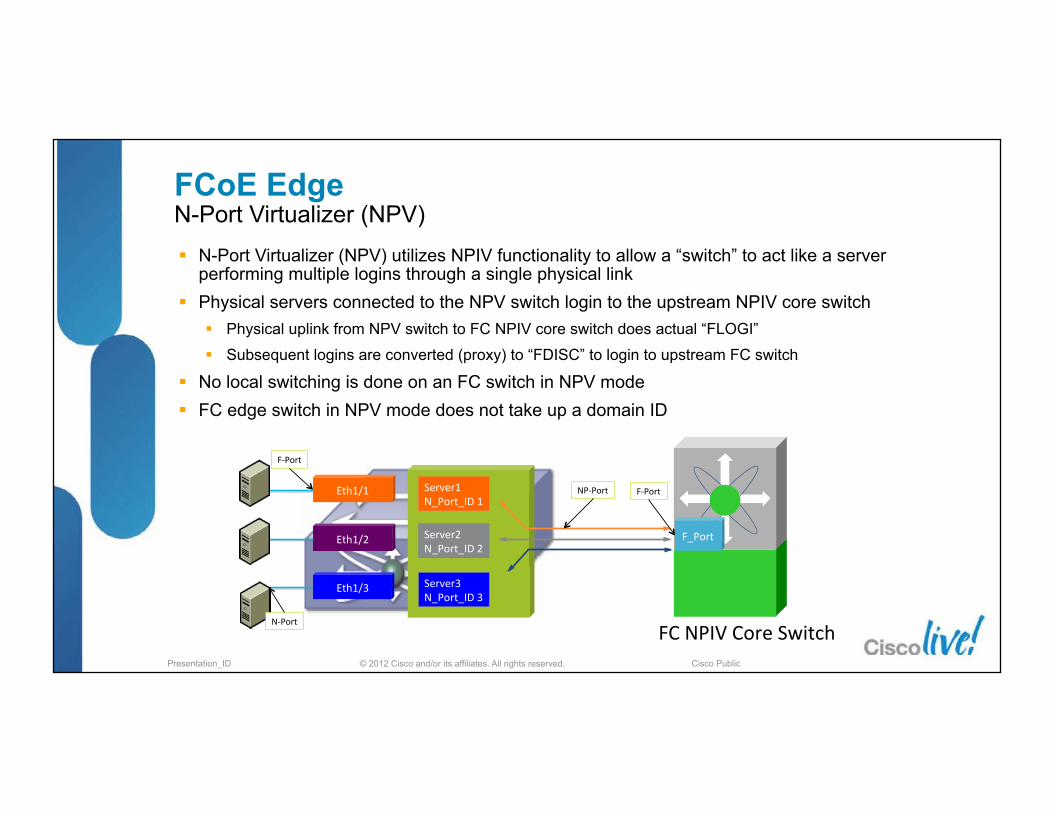
§ N-Port Virtualizer (NPV) utilizes NPIV functionality to allow a “switch” to act like a server performing multiple logins through a single physical link
§ Physical servers connected to the NPV switch login to the upstream NPIV core switch § Physical uplink from NPV switch to FC NPIV core switch does actual “FLOGI”
§ Subsequent logins are converted (proxy) to “FDISC” to login to upstream FC switch
§ No local switching is done on an FC switch in NPV mode § FC edge switch in NPV mode does not take up a domain ID
FC NPIV Core Switch
Eth1/1
Eth1/2
Eth1/3
Server1 N_Port_ID 1
Server2 N_Port_ID 2
Server3 N_Port_ID 3
F_Port
N-‐Port
F-‐Port
F-‐Port NP-‐Port
FCoE Edge N-Port Virtualizer (NPV)
© 2012 Cisco and/or its affiliates. All rights reserved. Presentation_ID Cisco Public
VLAN 10,30
VLAN 10,20
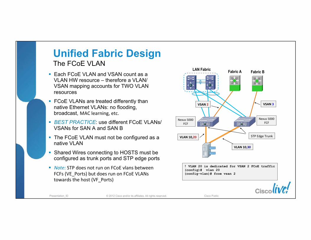
§ Each FCoE VLAN and VSAN count as a VLAN HW resource – therefore a VLAN/VSAN mapping accounts for TWO VLAN resources
§ FCoE VLANs are treated differently than native Ethernet VLANs: no flooding, broadcast, MAC learning, etc.
§ BEST PRACTICE: use different FCoE VLANs/VSANs for SAN A and SAN B
§ The FCoE VLAN must not be configured as a native VLAN
§ Shared Wires connecting to HOSTS must be configured as trunk ports and STP edge ports
§ Note: STP does not run on FCoE vlans between FCFs (VE_Ports) but does run on FCoE VLANs towards the host (VF_Ports)
! VLAN 20 is dedicated for VSAN 2 FCoE traffic (config)# vlan 20 (config-vlan)# fcoe vsan 2
VSAN 2
STP Edge Trunk
Fabric A Fabric B LAN Fabric
Nexus 5000 FCF
Nexus 5000 FCF
VSAN 3
Unified Fabric Design The FCoE VLAN

© 2012 Cisco and/or its affiliates. All rights reserved. Presentation_ID Cisco Public
§ With NX-OS release 4.2(1) Nexus 5000 supports F-Port Trunking and Channeling
§ VSAN Trunking and Port-Channel on the links between an NPV device and upstream FC switch (NP port -> F port)
§ F_Port Trunking: Better multiplexing of traffic using shared links (multiple VSANs on a common link)
§ F_Port Channeling: Better resiliency between NPV edge and Director Core (avoids tearing down all FLOGIs on a failing link)
§ Simplifies FC topology (single uplink from NPV device to FC director)
Fabric ‘A’ Supporting VSAN 20 & 40
F Port Trunking & Channeling
Unified Fabric Design F_Port Trunking and Channeling
VLAN 10,50
VLAN 10,30
VSAN 30,50
Fabric ‘B’ Supporting VSAN 30
& 50
VF
VN
TF
TNP
Server ‘1’ VSAN 20 & 30
Server ‘2’ VSAN 40 & 50

© 2012 Cisco and/or its affiliates. All rights reserved. Presentation_ID Cisco Public
Nexus 2232 10GE FEX
Fabric Extender - FEX Unified Fabric and FCoE
Nexus 5000 as FCF or as NPV
device
Nexus 5000/5500
Generation 2 CNAs
Fabric A Fabric B
FC
FCoE FC
§ Nexus 5000 access switches operating in NPV mode
§ With NX-OS release 4.2(1) Nexus 5000 supports F-Port Trunking and Channeling on the links between an NPV device and upstream FC switch (NP port -> F port)
§ F_Port Trunking: Better multiplexing of traffic using shared links (multiple VSANs on a common link)
§ F_Port Channeling: Better resiliency between NPV edge and Director Core
No host re-login needed per link failure No FSPF recalculation due to link failure
§ Simplifies FC topology (single uplink from NPV device to FC director)

© 2012 Cisco and/or its affiliates. All rights reserved. Presentation_ID Cisco Public
Unified Fabric Design FCoE and vPC together
Direct A�ach vPC Topology
VLAN 10,30
VLAN 10,20 STP Edge Trunk
VLAN 10 ONLY HERE!
Fabric A Fabric B LAN Fabric
Nexus 5000 FCF-‐A
Nexus 5000 FCF-‐B
vPC contains only 2 X 10GE links – one to each Nexus 5X00
§ vPC with FCoE are ONLY supported between hosts and N5k or N5k/2232 pairs…AND they must follow specific rules
§ A ‘vfc’ interface can only be associated with a single-‐port port-‐channel
§ While the port-‐channel configura�ons are the same on N5K-‐1 and N5K-‐2, the FCoE VLANs are different
§ FCoE VLANs are ‘not’ carried on the vPC peer-‐link (automa�cally pruned)
§ FCoE and FIP ethertypes are ‘not’ forwarded over the vPC peer link either
§ vPC carrying FCoE between two FCF’s is NOT supported
§ Best Prac�ce: Use sta�c port channel configura�on rather than LACP with vPC and Boot from SAN (this will change with future releases)

© 2012 Cisco and/or its affiliates. All rights reserved. Presentation_ID Cisco Public
EvPC & FEX Nexus 5550 Topologies starting with NX-OS 5.1(3)N1
§ In an Enhanced vPC (EvPC) SAN ‘A/B’ isolation is configured by associating each FEX with either SAN ‘A’ or SAN ‘B’ Nexus 5500
§ FCoE & FIP traffic is forwarded only over the links connected to the specific parent swicth
§ Ethernet is hashed over ‘all’ FEX fabric links
FCoE enabled server (dual CNA)
FCoE FC
N5K-A(config)# fex 100 N5K-A(config-fex)# fcoe N5K-A(config)# fex 101
N5K-B(config)# fex 101 N5K-B(config-fex)# fcoe N5K-B(config)# fex 100
FEX 101
FEX 100
N5K-B N5K-A

© 2012 Cisco and/or its affiliates. All rights reserved. Presentation_ID Cisco Public
§ VFC1 is bound to port-channel 1
§ Port-channel 1 is using LACP to negotiate with host
§ The VFC/port-channel never comes up and the host isn’t able to boot from SAN
SAN BSAN A
N5K(+N2K) as FCF or NPV DeviceN5K(+N2K) as FCF or NPV Device
1/2/4/8G FC10G Ethernet10G Unified I/O10G FCoE
LAN
N5K(+N2K) as FCF or NPV DeviceN5K(+N2K) as FCF or NPV Devicevfc 1
po-1 (vpc 1)Eth1/1 Eth1/1
Configurationinterface vfc 1
bind interface po-1
Configurationinterface vfc 2
bind interface po-1
po 1vfc 2po 1
vPC & Boot from SAN Pre 5.1(3)N1 Behaviour

© 2012 Cisco and/or its affiliates. All rights reserved. Presentation_ID Cisco Public
§ As of NX-OS Release 5.1(3)N1(1) for N5K, new VFC binding models will be supported § In this case, we now support VF_Port binding to a member port of a given port-channel § Check the configuration guide and operations guide for additional VFC binding changes
!
vPC & Boot from SAN5.1(3)N1 Behaviour
© 2012 Cisco and/or its affiliates. All rights reserved. Presentation_ID Cisco Public
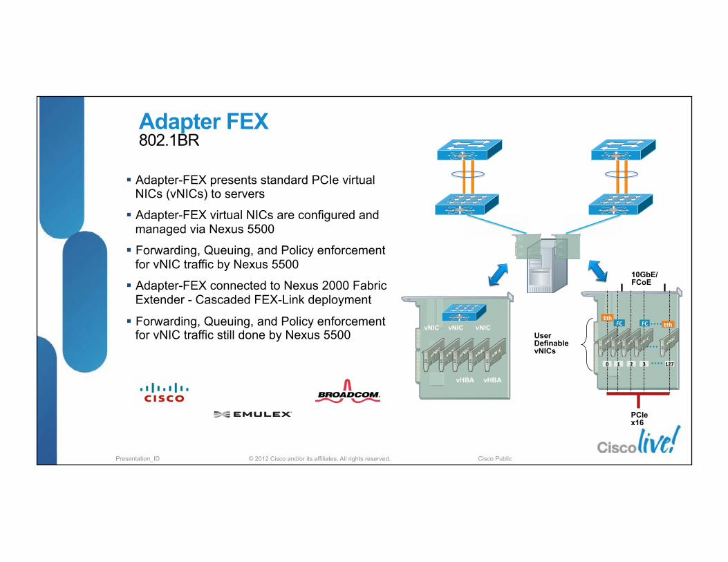
§ Adapter-FEX presents standard PCIe virtual NICs (vNICs) to servers
§ Adapter-FEX virtual NICs are configured and managed via Nexus 5500
§ Forwarding, Queuing, and Policy enforcement for vNIC traffic by Nexus 5500
§ Adapter-FEX connected to Nexus 2000 Fabric Extender - Cascaded FEX-Link deployment
§ Forwarding, Queuing, and Policy enforcement for vNIC traffic still done by Nexus 5500
vNIC vNIC vNIC
vHBA vHBA
PCIe x16
10GbE/FCoE
User Definable vNICs
Eth
0
FC
1 2
FC
3
Eth
127
Adapter FEX 802.1BR

© 2012 Cisco and/or its affiliates. All rights reserved. Presentation_ID Cisco Public
Working Group Ballot of Bridge Port Extension (P802.1BR), the IEEE standard for VNLink, has reached 100% approval by the voting members of the IEEE 802.1 committee.
November 10, the IEEE 802.1 committee passed a motion to advance the draft standard to Sponsor Ballot. This is the final stage for ratification of the standard.The first Sponsor Ballot is expected to take place in late November
Ratification of the standard is currently predicted for March 2012 The same is true for P802.1Qbg, which is the standard the includes some of the protocols that support Bridge Port Extension as well as the VEPA device being promoted by HP
Both standards are expected to be ratified in March.

© 2012 Cisco and/or its affiliates. All rights reserved. Presentation_ID Cisco Public
Adapter FEX & FCoE
CNA
FCoE
LAN SAN A
Nexus 5000 (San B)
Nexus 5000 (San A)
FCoE Storage
SAN B
vfc1
veth1
Bound to
Bound to
ethernet101/1/1
vfc2
veth2
Bound to
Bound to
ethernet102/1/1
Active Standby
Active Traffic Path
Let’s look a li�le more…
© 2012 Cisco and/or its affiliates. All rights reserved. Presentation_ID Cisco Public
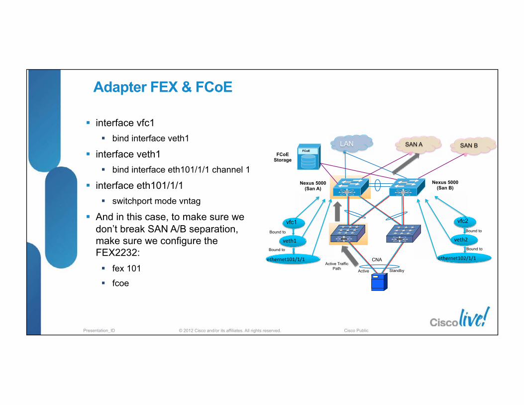
§ interface vfc1 § bind interface veth1
§ interface veth1 § bind interface eth101/1/1 channel 1
§ interface eth101/1/1 § switchport mode vntag
§ And in this case, to make sure we don’t break SAN A/B separation, make sure we configure the FEX2232: § fex 101
§ fcoe
CNA
FCoE
LAN SAN A
Nexus 5000 (San B)
Nexus 5000 (San A)
FCoE Storage
SAN B
vfc1
veth1 Bound to
Bound to
ethernet101/1/1
vfc2
veth2 Bound to
Bound to
ethernet102/1/1
Active Standby
Active Traffic Path
Adapter FEX & FCoE

© 2012 Cisco and/or its affiliates. All rights reserved. Presentation_ID Cisco Public
Transparent Bridges? FIP Snooping
ENode
ENode MAC 0E.FC.00.07.08.09
FIP Snooping Spoofed MAC 0E.FC.00.DD.EE.FF
FCF FCF MAC
0E.FC.00.DD.EE.FF
§ What does a FIP Snooping device do?
§ FIP solicita�ons (VLAN Disc, FCF Disc and FLOGI) sent out from the CNA and FIP responses from the FCF are “snooped”
§ How does a FIP Snooping device work?
§ The FIP Snooping device will be able to know which FCFs hosts are logged into
§ Will dynamically create an ACL to make sure that the host to FCF path is kept secure
§ A FIP Snooping device has NO intelligence or impact on FCoE traffic/path selec�on/load balancing/login selec�on/etc
§ Men�oned in the Annex of the FC-‐BB-‐5 (FCoE) standard as a way to provide security in FCoE environments
§ Supported on Nexus 5000/5500 – 4.1(3)
§ Supported on Nexus 7000 -‐ 6.1(1) with F2, F1 cards
VF
VN

© 2012 Cisco and/or its affiliates. All rights reserved. Presentation_ID Cisco Public
Fibre Channel Aware Device FCoE NPV
FCF
§ What does an FCoE-‐NPV device do? § ”FCoE NPV bridge" improves over a "FIP snooping
bridge" by intelligently proxying FIP func�ons between a CNA and an FCF
§ Ac�ve Fibre Channel forwarding and security element
§ FCoE-‐NPV load balance logins from the CNAs evenly across the available FCF uplink ports
§ FCoE NPV will take VSAN into account when mapping or ‘pinning’ logins from a CNA to an FCF uplink
§ Emulates exis�ng Fibre Channel Topology (same mgmt, security, HA, …)
§ Avoids Flooded Discovery and Configura�on (FIP & RIP)
Fibre Channel Configura�on and Control Applied at the Edge Port
Proxy FCoE VLAN Discovery
Proxy FCoE FCF Discovery
FCoE NPV
VF
VNP

© 2012 Cisco and/or its affiliates. All rights reserved. Presentation_ID Cisco Public
FCoE NPV: Fabric Login
VF-port
VF-port
VN-port
Initiator
Target FC Switch
FCoE-NPIV Core Switch
VNP-port
FC Link
FCoE Link
FCoE NPV Switch
FCoE Target
FLO
GI
FCID FPMA FPMA FCoE NPV core and FCoE NPV edge switches go
through FIP Nego�a�on process* (*explained in next slides) FCoE NPV edge switch does a fabric login (FLOGI)
into NPV core switch
FCoE NPV Core assigns FCID and Fabric Provided Mac-Address (FPMA) to FCoE NPV edge switch

© 2012 Cisco and/or its affiliates. All rights reserved. Presentation_ID Cisco Public
FCoE NPV: FIP VLAN Discovery
VF-port
VF-port
VN-port
Initiator
Target FC Switch
FCoE-NPIV Core Switch
VNP-port
FC Link
FCoE Link
FCoE NPV Switch
FCoE Target
FIP VLAN Discovery
FIP VLAN No�fica�on FCoE VLAN=5
FCoE VLAN=5
FcoE Initialization Protocol (FIP) is used to discover FCoE VLAN between the Initiator and FCF Initiator CNA sends FIP VLAN Discovery packets,
gets forwarded to FCoE NPV core switch Initiator discovers FCoE VLAN (VLAN=5) which
will be used for FCoE communication

© 2012 Cisco and/or its affiliates. All rights reserved. Presentation_ID Cisco Public
FCoE NPV: FIP FCF Discovery
VF-port
VF-port
VN-port
Initiator
Target FC Switch
FCoE-NPIV Core Switch
VNP-port
FC Link
FCoE Link
FCoE NPV Switch
FCoE Target
FIP FCF Solicita�on
FIP FCF Adver�sement
FCF Discovered Name=SwitchWWNMAC=FCF-
MAC
The Initiator sends FCF solicitation message with destination MAC address ALL-FCF-MAC, FCoE NPV switch forwards to FCoE NPV core switch
NPV core switch responds with FCF advertisement containing its own MAC addressand fabric related details
Initiator detects FCF along with FCF-MAC and switch WWN

© 2012 Cisco and/or its affiliates. All rights reserved. Presentation_ID Cisco Public
FCoE NPV: Fabric Login
VF-port
VF-port
VN-port
Initiator
Target FC Switch
FCoE-NPIV Core Switch
VNP-port
FC Link
FCoE Link
FCoE NPV Switch
FCoE Target
FCID FPMA
FLO
GI
FPMA
NOTE: FCoE NPV does NOT convert server FLOGI to FDISC like FC NPV
Initiator gets the FCID & the Fabric Assigned MAC-Address (FPMA)
Initiator sends a fabric login (FLOGI) towards FCoE NPV edge switch FLOGI is forwarded towards FCoE NPV core
switch without changing it into FDISC FCoE NPV core switch responds with FCID
and FPMA for the Initiator This FPMA will be used by the Initiator for all
its FCoE related communication

© 2012 Cisco and/or its affiliates. All rights reserved. Presentation_ID Cisco Public
FCoE-NPV configuration Details
n5k(config)# feature fcoe-‐npv
Proper no drop QOS needs to be applied to all NPIV VDC’s and NPV switches as shown in
earlier slides
N7K Storage VDC n7k-‐fcoe(config)# feature npiv
N5K’s with release 5.2.x
MDS w/ release 5.2.x
MDS Global command MDS9513-‐71# feature npiv
LACP Port-‐channels an be configured between switches for High availability.
Becomes VNP to VF
N7K w/ release 5.2.x
N5K’s with release 5.2.x

© 2012 Cisco and/or its affiliates. All rights reserved. Presentation_ID Cisco Public
Benefits DCB FIP Snooping FCoE NPV FCoE Switch
Scalability (Server connectivity) ✔ ✔ ✔ ✔
Support for Lossless Ethernet ✔ ✔ ✔ ✔
FCoE Traffic Engineering ✗ ✗ ✔ ✔
Security (Man in the middle attack) ✗ ✔ ✔ ✔
FC to FCoE Migration (Ease of FCoE device
migration from FC fabric to FCoE network)
✗ ✗ ✔ ✔ FCoE Traffic Load
Balancing ✗ ✗ ✔ ✔ SAN Administration
(VSAN, VFC visibility for SAN Administration) ✗ ✗ ✔ ✔
FCoE NPV Edge Capabilities
For Your Reference

© 2012 Cisco and/or its affiliates. All rights reserved. Presentation_ID Cisco Public
FCoE - Design, Operations and Management Best Practices Agenda
§ Unified Fabric – What and When § FCoE Protocol Fundamentals § Nexus FCoE Capabilities
§ FCoE Network Requirements and Design Considerations
§ DCB & QoS - Ethernet Enhancements § Single Hop Design § Multi-Hop Design
§ Futures
1K Cisco Nexus
x86
© 2012 Cisco and/or its affiliates. All rights reserved. Presentation_ID Cisco Public
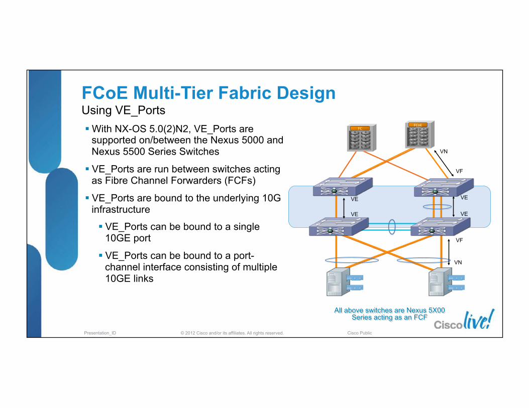
FCoE Multi-Tier Fabric Design Using VE_Ports § With NX-OS 5.0(2)N2, VE_Ports are
supported on/between the Nexus 5000 and Nexus 5500 Series Switches
§ VE_Ports are run between switches acting as Fibre Channel Forwarders (FCFs)
§ VE_Ports are bound to the underlying 10G infrastructure
§ VE_Ports can be bound to a single 10GE port
§ VE_Ports can be bound to a port-channel interface consisting of multiple 10GE links
VN
VE
VF
VE
VF
VN
FCoE FC
All above switches are Nexus 5X00 Series acting as an FCF
VE
VE

© 2012 Cisco and/or its affiliates. All rights reserved. Presentation_ID Cisco Public
What happens when FCF’’s are connected via VE_Ports
§ 10Gig Ethernet ISL or LACP port-channel must first be established between FCF Switches expanding the L2 ethernet network
§ LLDP frames with DCBx TLV’s, sourcing the MAC addresses of each switch are exchanged across the ethernet Link to determine abilities.
§ FIP Control exchange is done between switches § FSPF routing established § Fibre Channel Protocol is exchanged between the FCF’s and a Fibre
Channel merge of Zones is accomplished building out the FC SAN. § You now have established a VE_Port between two DCB switches
Dedicated FCoE Link

© 2012 Cisco and/or its affiliates. All rights reserved. Presentation_ID Cisco Public
VE_Port FIP exchange A FIP ELP (Exchange Link Parameter)is sent on each VLAN by both the N5K, N7K or MDS. A FIP ACC is sent by the switch for each VLAN.
Discovery Solicita�ons & Adver�sements from the FCF are sent both ways across the VE_Port, one for each FCoE mapped VLAN that is trunked on the interface.

© 2012 Cisco and/or its affiliates. All rights reserved. Presentation_ID Cisco Public
FCoE VE - Fibre Channel E_Port handshake
Domain ID Assign by Existing Principal Switch
Request Domain ID from New Switch
Exchange Fabric Parameters
Zone Merge Request
Enhanced Zoning Merge Request Resource Allocation
Build Fabric
FSPF exchanges

© 2012 Cisco and/or its affiliates. All rights reserved. Presentation_ID Cisco Public
Differences in Trunking VSANs with FCoE VE_Ports
§ In FC on the MDS, trunking is used to carry multiple VSANs over the same physical FC link. With FCoE, a physical link is replaced by a virtual link, a pair of MAC addresses.
§ FCoE uses assigned MAC addresses that are unique only in the context of a single FC fabric. Carrying multiple fabrics over a single VLAN would then mean having a strong possibility for duplicated MAC addresses.
§ In FCoE there cannot be more than one VSAN mapped over a VLAN. § The net result is that trunking is done at the Ethernet level, not at the FC level.
§ FC trunking is not needed and the Fibre Channel Exchange Switch Capabilities(ESC) & Exchange Port Parameters (EPP) processing is not required to be performed as on the MDS

© 2012 Cisco and/or its affiliates. All rights reserved. Presentation_ID Cisco Public
FCoE Extension Options
§ Requirement: Maintain loss-less behavior across the point-to-point link
§ Supported distance is governed by the ingress buffer size available on the switch
3 km
3 km
20 km
10 km1
1. Limited by supported Optics
FCoE IP FCIP
FCoE
FCoE Dedicated
FC
Point-to-point FC
Speed (Gbps)
Max Distance (KM)
1 8000
2 4000
4 2000
8 1000
10 680
Short Distance Options Longer Distance Options
FCoE Convereged

© 2012 Cisco and/or its affiliates. All rights reserved. Presentation_ID Cisco Public
Multi - Hop Design Extending FCoE to MDS SAN from Aggregation
Ethernet Fibre Channel
Dedicated FCoE Link Converged Link
FC FCoE
AGG
Access
CORE
L3
L2
N7K
MDS FC SAN A MDS FC SAN B
N7K
N7K N7K
§ Converged Network into the existing SAN Core
§ Leverage FCoE wires between Fibre Channel SAN to Ethernet DCB switches in Aggregation layer using Dedicated ports
§ Maintain the A – B SAN Topology with Storage VDC and Dedicated wires
§ Using N7K director Class Switches at Access layer
§ Dedicated FCoE Ports between access and Aggregation, vPC’s for Data
§ Zoning controlled by Core A-B SAN

© 2012 Cisco and/or its affiliates. All rights reserved. Presentation_ID Cisco Public
Storage on MDS Extending FCoE to MDS SAN from Access
Ethernet Fibre Channel
Dedicated FCoE Link Converged Link
AGG
Access
CORE
L3
L2
N5K
MDS FC SAN A MDS FC SAN B
FC FCoE
N5K
§ Converged Network capabilities to the existing SAN Core
§ Leverage FCoE wires between Fibre Channel SAN to Ethernet DCB switches (VE_Ports)
§ N5K access switches can be in Fibre Channel switch node and assigned Domain ID , or N5K access switches can run in FCoE-NPV mode, no FC services running local.
§ Zoning controlled by Core A-B SAN

© 2012 Cisco and/or its affiliates. All rights reserved. Presentation_ID Cisco Public
Migration of Storage to Aggregation § Different requirements for LAN and
SAN network designs
§ Factors that will influence this use case § Port density
§ Operational roles and change management
§ Storage device types
§ Potentially viable for smaller environments
§ Larger environments will need dedicated FCoE ‘‘SAN’’ devices providing target ports § Use connections to a SAN
§ Use a “storage” edge of other FCoE/DCB capable devices
Ethernet Fibre Channel
Dedicated FCoE Link Converged Link
AGG
Access
CORE
L3
L2
N5K
SAN A SAN B
FCoE
N5K
Multiple VDCs FCoE SAN LAN Agg LAN Core
SAN Admins manage Storage VDC Zoning Login Services

© 2012 Cisco and/or its affiliates. All rights reserved. Presentation_ID Cisco Public
SAN B SAN A
§ Does passing FCoE traffic through a larger aggregation point make sense?
§ Multiple links required to support the HA models
§ 1:1 ratio between access to aggregation and aggregation to SAN core is required
§ Need to plan for appropriate capacity in any core VE_Port link
§ When is a direct Edge to Core links for FCoE are more cost effective than adding another hop?
§ Smaller Edge device more likely to be able to use under-provisioned uplinks
1:1 Ratio of links required unless
FCoE-NPV FCoE uplink is
over-provisioned
CORE
Congestion on Agg-Core
links Require
proper sizing
FCoE Deployment Considerations Shared Aggregation/Core Devices
Ethernet Fibre Channel
Dedicated FCoE Link Converged Link

© 2012 Cisco and/or its affiliates. All rights reserved. Presentation_ID Cisco Public
Data Center Network Manager
DCNM
DCNM (Converged)
DCNM-SAN DESKTOP
CLIENT
Fabric Manager FMS
One converged product § Single pane of glass (web 2.0 dashboard) § Common operations (discovery, topology) § Single installer, Role based access control § Consistent licensing model (licenses on server) § Integration with UCS Manager and other OSS tools
DCNM-LAN DESKTOP
CLIENT

© 2012 Cisco and/or its affiliates. All rights reserved. Presentation_ID Cisco Public
LAN/SAN Roles Data Center Network Manager
§ Collaborative management § Defined roles & functions § FCoE Wizards
Nexus 7000
Tasks Tools
LAN Admin
Storage VDC provisioning VLAN management Ethernet config (L2, network security, VPC, QoS, etc. DCB Configuration (VL, PFC, ETS Templates)
DCNM-LAN
SAN Admin
Discovery of Storage VDCs VLAN-VSAN mapping (use reserved pool) Wizard vFC provisioning Wizard Zoning
DCNM-SAN
FCoE Wizards

© 2012 Cisco and/or its affiliates. All rights reserved. Presentation_ID Cisco Public
FCoE - Design, Operations and Management Best Practices Agenda
§ Unified Fabric – What and When § FCoE Protocol Fundamentals § Nexus FCoE Capabilities
§ FCoE Network Requirements and Design Considerations
§ DCB & QoS - Ethernet Enhancements § Single Hop Design § Multi-Hop Design
§ Futures
1K Cisco Nexus
x86

© 2012 Cisco and/or its affiliates. All rights reserved. Presentation_ID Cisco Public
Data Center Design with E-SAN
§ Same topologies as existing networks, but using Nexus Unified Fabric Ethernet switches for SANs
§ Physical and Logical separation of LAN and SAN traffic
§ Additional Physical and Logical separation of SAN fabrics
§ Ethernet SAN Fabric carries FC/FCoE & IP based storage (iSCSI, NAS, …)
§ Common components: Ethernet Capacity and Cost
Ethernet LAN and Ethernet SAN
CNA
L2
L3
NIC or CNA
Isolation
Fabric ‘A’ Fabric ‘B’
FCoE
Nexus 7000 Nexus 5000
Nexus 7000 Nexus 5000
FC
Ethernet
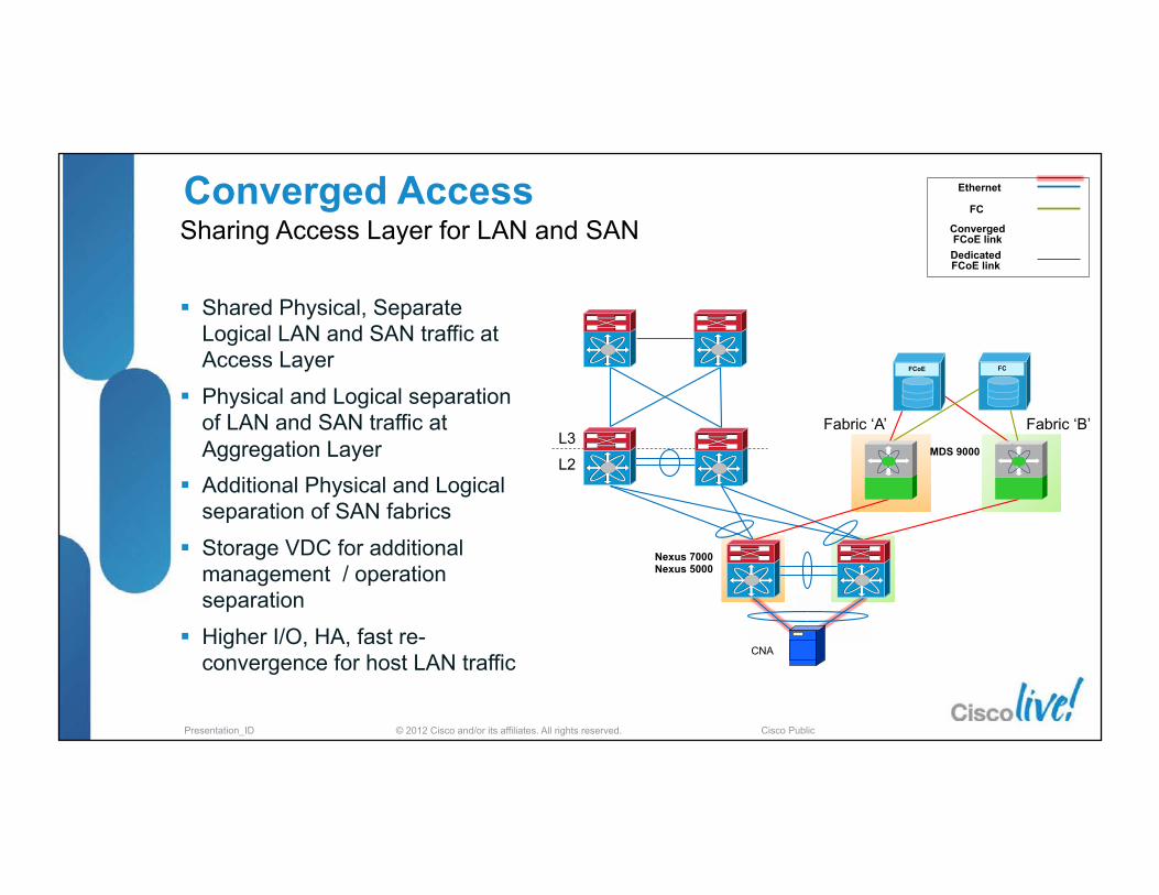
© 2012 Cisco and/or its affiliates. All rights reserved. Presentation_ID Cisco Public
Converged Access
§ Shared Physical, Separate Logical LAN and SAN traffic at Access Layer
§ Physical and Logical separation of LAN and SAN traffic at Aggregation Layer
§ Additional Physical and Logical separation of SAN fabrics
§ Storage VDC for additional management / operation separation
§ Higher I/O, HA, fast re-convergence for host LAN traffic
Sharing Access Layer for LAN and SAN
L2
L3
CNA
Fabric ‘A’ Fabric ‘B’
FC FCoE
Nexus 7000 Nexus 5000
MDS 9000
Converged FCoE link Dedicated FCoE link
FC
Ethernet

© 2012 Cisco and/or its affiliates. All rights reserved. Presentation_ID Cisco Public
……
§ LAN and SAN traffic share physical switches
§ LAN and SAN traffic use dedicated links between switches
§ All Access and Aggregation switches are FCoE FCF switches
§ Dedicated links between switches are VE_Ports
§ Storage VDC for additional operation separation at high function agg/core
§ Improved HA, load sharing and scale for LAN vs. traditional STP topologies
§ SAN can utilize higher performance, higher density, lower cost Ethernet switches for the aggregation/core
Maintaining Dual SAN fabrics with Overlay
L2
L3
CNA FC FCoE
Nexus 7000 Nexus 5000
Converged FCoE link Dedicated FCoE link
FC
Ethernet
FCF FCF
FCF
VE
Fabric ‘A’
Fabric ‘B’
LAN/SAN
Converged Network Fabrics with Dedicated Links
MDS 9500

© 2012 Cisco and/or its affiliates. All rights reserved. Presentation_ID Cisco Public
Converged Network with Dedicated Links
§ FabricPath enabled for LAN traffic § Dual Switch core for SAN A & SAN B § All Access and Aggregation switches
are FCoE FCF switches § Dedicated links between switches
are VE_Ports § Storage VDC for additional operation
separation at high function agg/core
§ Improved HA and scale over vPC (ISIS, RPF, … and N+1 redundancy)
§ SAN can utilize higher performance, higher density, lower cost Ethernet switches
Maintaining Dual SAN fabrics with FabricPath
L2
L3
CNA
Convergence
FC FCoE
Nexus 7000 Nexus 5000
Fabric ‘A’
Fabric ‘B’
FCF
FCF
FCF
FCF
VE
Converged FCoE link Dedicated FCoE link
FC
Ethernet
FabricPath
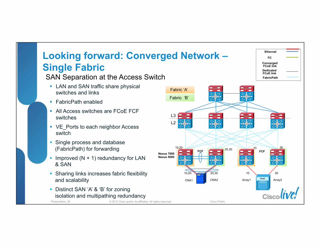
© 2012 Cisco and/or its affiliates. All rights reserved. Presentation_ID Cisco Public
Converged FCoE link Dedicated FCoE link
FC
Ethernet
FabricPath
Looking forward: Converged Network – Single Fabric SAN Separation at the Access Switch
L2
L3
FCoE
Nexus 7000 Nexus 5000
FCF FCF
CNA1 CNA2
10,20 20,30 10 30
Array1 Array2
10,20 20,30 10 30
Fabric ‘A’
Fabric ‘B’
§ LAN and SAN traffic share physical switches and links
§ FabricPath enabled
§ All Access switches are FCoE FCF switches
§ VE_Ports to each neighbor Access switch
§ Single process and database (FabricPath) for forwarding
§ Improved (N + 1) redundancy for LAN & SAN
§ Sharing links increases fabric flexibility and scalability
§ Distinct SAN ‘A’ & ‘B’ for zoning isolation and multipathing redundancy

© 2012 Cisco and/or its affiliates. All rights reserved. Presentation_ID Cisco Public
Converged FCoE link Dedicated FCoE link
FC
Ethernet
FabricPath
Looking forward: Converged Network – Single Fabric FC-BB-6
L2
L3
FCoE
Nexus 7000 Nexus 5000
FCF FDF
CNA1 CNA2
10,20 20,30 10 30
Array1 Array2
10,20 20,30 10 30
Fabric ‘A’
Fabric ‘B’
§ LAN and SAN traffic share physical switches and links
§ FabricPath enabled
§ VA_Ports to each neighbor FCF switch
§ Single Domain
§ FDF to FCF transparent failover
§ Single process and database Single process and database (FabricPath) for forwarding
§ Improved (N + 1) redundancy for LAN & SAN
§ Sharing links increases fabric flexibility and scalability
§ Distinct SAN ‘A’ & ‘B’ for zoning isolation and multipathing redundancy
VA_Ports VA_Ports VA_Ports VA_Ports

© 2012 Cisco and/or its affiliates. All rights reserved. Presentation_ID Cisco Public
Unified Multi-Tier Fabric Design Current Model – 2010 & 2011
§ All devices in the server storage path are Fibre Channel Aware § Evolutionary approach to migration to Ethernet transport for Block storage § FC-BB-6 and FabricPath (L2MP) may provide enhancements but need to be aware of
your ability to evolve
Ethernet Fabric
FC Fabric
FC Domain 7 FC Domain 3 MAC A
FCID 7.1.1
FCID 1.1.1 MAC C
D_ID = FC-‐ID (1.1.1) S_ID = FC-‐ID (7.1.1)
FC Frame
D_ID = FC-‐ID (1.1.1) S_ID = FC-‐ID (7.1.1)
FC Frame
Ethernet Fabric
FC Domain 1 MAC B
FC Storage
FCoE Frame
D_ID = FC-‐ID (1.1.1) S_ID = FC-‐ID (7.1.1)
Dest. = MAC B Srce. = MAC A
D_ID = FC-‐ID (1.1.1) S_ID = FC-‐ID (7.1.1)
Dest. = MAC C Srce. = MAC B
FC link
VE_port VE_port VF_port VN_port
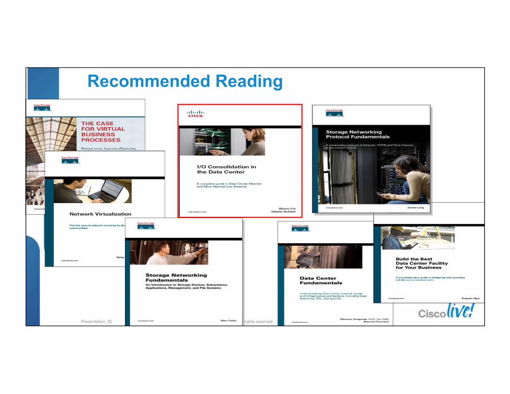
© 2012 Cisco and/or its affiliates. All rights reserved. Presentation_ID Cisco Public
Recommended Reading

© 2012 Cisco and/or its affiliates. All rights reserved. Presentation_ID Cisco Public
Appendix : Larger scale FCoE Design References

© 2012 Cisco and/or its affiliates. All rights reserved. Presentation_ID Cisco Public
Converged Access Design
Access (SAN Edge): 2 x Cisco Nexus 7018 896 ports to Hosts @ 10G 64 ports to SAN Core @ 10G
Total 2 Host Edge Switches
16 16
Overall Oversubscription 7:1
896 Host Ports
64 Storage Ports
16 16
FCoE FCoE FCoE FCoE
FCoE
Populated w/16 Line-cards Each card having:
2 ports @ 10G to SAN Core – Dedicated FCoE 2 ports @ 10G to LAN Core – Ethernet(1)
28 ports @ 10G to Hosts Total of 448 ports @ 10G to Hosts
Populated w/ 8 Line-cards Each card having:
4 Storage ports @10G 4 Edge ports @ 10G –
Dedicated FCoE SAN Core:
2 x Cisco MDS 9513 Total 64 Storage Ports ↑ Total 64 Edge Ports ↓
Analogous to a SAN Core-Edge Design
Notes: 1. Classical Ethernet LAN connections not shown. 2. This sample is only SAN A (or B) portion of the network. 3. Shared Links to the hosts allocate 50% of bandwidth to FCoE traffic.

© 2012 Cisco and/or its affiliates. All rights reserved. Presentation_ID Cisco Public
Converged Network Design
Notes: 1. Classical Ethernet LAN connections not shown. 2. This sample is only SAN A (or B) portion of the network. 3. Shared Links to the hosts allocate 50% of bandwidth to FCoE traffic.
Analogous to a SAN Edge-Core-Edge Design
Aggrega�on
FCoE FCoE FCoE FCoE FCoE FCoE
32 32 32 32
40 44 44
SAN Edge: 3 x Cisco MDS 9513 128 Storage ports @ 10G 128 Core ports @ 10G
Total 3 Storage Edge Switches
Access (SAN Edge) 4 x Cisco Nexus 7018 1,792 ports to Hosts @ 10G 128 ports to Core @ 10G
Total 4 Host Edge Switches
Overall Oversubscription 7:1
1,792 Host Ports
128 Storage Ports
Populated w/ 16 Line-cards: 2 ports @ 10G to Core – Dedicated FCoE 2 ports @ 10G to Core – Ethernet(1)
28 ports @ 10G to Hosts Total of 448 ports @ 10G to Hosts
Aggrega�on (SAN Core): Populated w/ 8 Line-‐cards:
256 ports @ 10G
Populated w/ 11 Line-‐cards: 4 ports @ 10G to Storage 4 ports @ 10G to Core
Access
SAN Edge

© 2012 Cisco and/or its affiliates. All rights reserved. Presentation_ID Cisco Public
Converged Network Design
Access (SAN Edge) 4 x Cisco Nexus7018 1,792 ports to Hosts @ 10G 128 ports to Core @ 10G
Total 4 Host Edge Switches
FCoE FCoE
32 32 32 32
Overall Oversubscription 7:1
1,792 Host Ports
128 Storage Ports
Notes: 1. Classical Ethernet LAN connections not shown. 2. This sample is only SAN A (or B) portion of the network. 3. Converged Links to the hosts allocate 50% of bandwidth to FCoE traffic.
FCoE
Populated w/ 16 Line-cards 2 ports @ 10G to Core – Dedicated FCoE 2 ports @ 10G to Core – Ethernet(1)
28 ports @ 10G to Hosts Total of 448 ports @ 10G to Hosts
Aggrega�on (SAN Core) Populated w/ 8 Line-‐cards:
128 Storage ports @ 10G 128 Core ports @ 10G
Access
Aggrega�on
Analogous to a SAN Core-Edge Design
© 2012 Cisco and/or its affiliates. All rights reserved. Presentation_ID Cisco Public
Complete Your Online Session Evaluation § Give us your feedback and you
could win fabulous prizes. Winners announced daily.
§ Receive 20 Passport points for each session evaluation you complete.
§ Complete your session evaluation online now (open a browser through our wireless network to access our portal) or visit one of the Internet stations throughout the Convention Center.
Don’t forget to activate your Cisco Live Virtual account for access to all session material, communities, and on-demand and live activities throughout the year. Activate your account at the Cisco booth in the World of Solutions or visit www.ciscolive.com.
120

© 2012 Cisco and/or its affiliates. All rights reserved. Presentation_ID Cisco Public © 2012 Cisco and/or its affiliates. All rights reserved. Presentation_ID Cisco Public