FCI LT LM UNDERGROUND - Trydor | 3 | FCI ‐ LT‐LM, UNDERGROUND NAVIGATOR – August 2, 2016 –...
11
DIPL.‐ING. H. Horstmann GmbH. Faulted Circuit Indicators Page | 1 | FCI ‐ LT‐LM, UNDERGROUND NAVIGATOR – August 2, 2016 – D.Tyers FCI – LT ‐ LM UNDERGROUND F a u l t e d C i r c u i t Indicator for Underground Applications ‐ Catalogue #’s #29‐6028‐000 PPZ, #29‐6015‐000 PPZ, # 29‐6228‐000, #29‐6215‐000 Description The Navigator LT‐LM (Load Tracking, Load Memory) is the latest generation of faulted circuit indicators, utilizing many years of experience, from the Horstmann Company. Designed for underground distribution circuits, the LT‐LM PPZ fault indicator quickly and accurately aids trouble crews in determining the status of the system and the location of faults. Installed on bare or covered conductor the unique design allows for easy installation and/or removal with a hot stick or Grip All Tool. These FCI’s are held in place by an extremely strong spring loaded mechanism for mounting surfaces, the Navigator can be mounted at any angle from vertical to horizontal. The LT‐LM housing is sealed to operate in adverse outdoor conditions. The housing materials are corrosion and UV protected polyamide, polycarbonate and stainless steel. There are no moving mechanical parts to wear or fatigue, therefore trip current calibration remains constant throughout the life of the indicator. FCI ‐ LT ‐ LM Series Fault Indicators are primarily designed for utility underground cables, where phase to phase spacing is limited. The closed core, cable clamping mechanism is designed to significantly reduce the proximity effect of adjacent cables and for easy installation and/or removal with a hot stick. Coordination with circuit protection devices is accomplished through the use of a single fault trip curve. The shape of the curve is referred to as Protection Mated. Protection Mated (PM) means the curve’s shape is designed to coordinate with to‐ day’s electronic protection devices and to avoid improper indication on circuit inrush. Through closer coordination and PPZ reset the frequency of false tripping is greatly reduced. Constantly monitoring current magnitude (load), the fault indicator is installed at a point on the cable where the ground current return path has no influence. The fault curve is adjusted electronically in relation to the load and thus referred to as load tracking (LT).
Transcript of FCI LT LM UNDERGROUND - Trydor | 3 | FCI ‐ LT‐LM, UNDERGROUND NAVIGATOR – August 2, 2016 –...

DIPL.‐ING.
H. Horstmann GmbH.Faulted Circuit Indicators
Page | 1 | FCI ‐ LT‐LM, UNDERGROUND NAVIGATOR – August 2, 2016 – D.Tyers
F C I – L T ‐ L M U N D E R G R O U N D
Faulted Circuit Indicator for Underground Applications ‐ Catalogue #’s
#29‐6028‐000 PPZ, #29‐6015‐000 PPZ, #29‐6228‐000, #29‐6215‐000
Description
The Navigator LT‐LM (Load Tracking, Load Memory) is the latest generation of faulted circuit indicators, utilizing many years of experience, from the Horstmann Company.
Designed for underground distribution circuits, the LT‐LM PPZ fault indicator quickly and accurately aids trouble crews in determining the status of the system and the location of faults. Installed on bare or covered conductor the unique design allows for easy installation and/or removal with a hot stick or Grip All Tool. These FCI’s are held in place by an extremely strong spring loaded mechanism for mounting surfaces, the Navigator can be mounted at any angle from vertical to horizontal.
The LT‐LM housing is sealed to operate in adverse outdoor conditions. The housing materials are corrosion and UV protected polyamide, polycarbonate and stainless steel. There are no moving mechanical parts to wear or fatigue, therefore trip current calibration remains constant throughout the life of the indicator.
FCI ‐ LT ‐ LM Series Fault Indicators are primarily designed for utility underground
cables, where phase to phase spacing is limited. The closed core, cable clamping
mechanism is designed to significantly reduce the proximity effect of adjacent cables
and for easy installation and/or removal with a hot stick.
Coordination with circuit protection devices is accomplished through the use of a
single fault trip curve. The shape of the curve is referred to as Protection Mated.
Protection Mated (PM) means the curve’s shape is designed to coordinate with to‐
day’s electronic protection devices and to avoid improper indication on circuit inrush.
Through closer coordination and PPZ reset the frequency of false tripping is greatly
reduced.
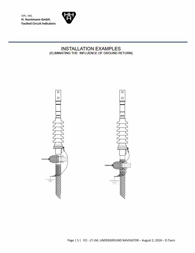
Constantly monitoring current magnitude (load), the fault indicator is installed at a point on the cable where the
ground current return path has no influence. The fault curve is adjusted electronically in relation to the load and
thus referred to as load tracking (LT).
twhite
Available from Trydor

DIPL.‐ING.
H. Horstmann GmbH.Faulted Circuit Indicators
Page | 2 | FCI ‐ LT‐LM, UNDERGROUND NAVIGATOR – August 2, 2016 – D.Tyers
Load Memory (LM) describes how quickly the characteristic curve is adjusted. The highest continuous current
sensed for at least 60 seconds will establish a fault curve position in memory and hold it for 72 hours. If the load‐current reaches or exceeds the stored value, a new fault curve position is registered and the memory time
of 72 hours starts again. If load current does not meet or exceed the established level for 72 hours, the LT‐LM
will then sense and re‐establish a new lower fault curve position.
The electronic system is encapsulated in a resin compound enabling the fault indicator to operate fully submersed
according to IEEE standard. There are no moving mechanical parts to wear. Not dependent on cable size, “one size
fits all”.
Fault detection is indicated by a super bright flashing RED LED, giving excellent all round visibility.
All Version LT ‐ LM indicators are reset by time, factory set at 4 hours.
Catalogue 29‐6028‐000 units also reset by current during a one‐time sequence
known as Pulse‐Pause‐Zero. After detection of a fault (Pulse) and a 28 second delay (Pause), a current sensor is enabled for a further 28 seconds to reset the
FCI if cur‐rents > 5 A, 60 Hz. are detected. If currents < 5 A are detected (Zero) no reset signal is sent. Thereafter the current sensor is disabled from resetting
the FCI, and reset occurs by timing out of the counter or by manual means.
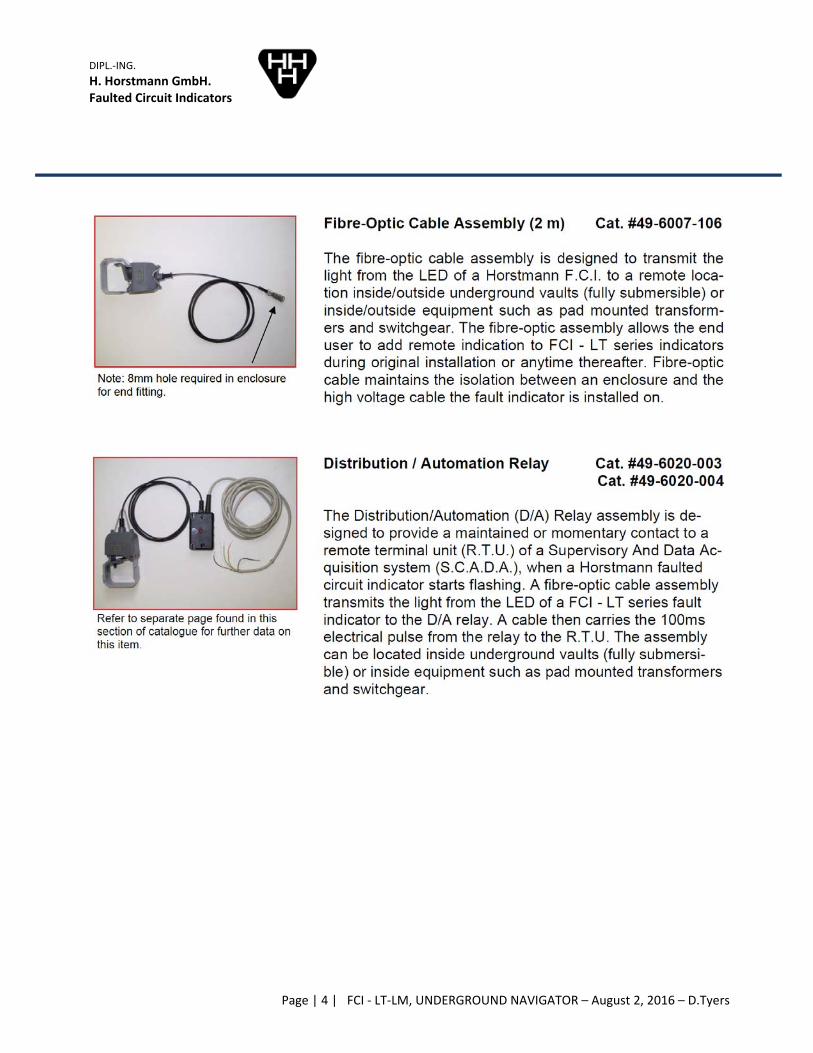
Remote indication is available as a separate fiber‐optic cable assembly that is
in‐stalled on a standard single phase unit by the end user (three phase not available). For connection to Supervisory Control and Data Acquisition
(SCADA) systems a Distribution Automation (D/A) relay is available and may be added by the end user at any time.
The LT‐LM UNDERGROUND NAVIGATOR detects fault events and provides a digital LED Strobe demonstrating that
the fault has passed the given point.
The load leveling (LM) and load memory feature enables the unit to automatically set fault trip current rating in
relation to peak load current. Once the unit detects fault current above its trip current rating the FCI sends signal
to the Red Strobe LED and the RED LED begins to flash. Cold Load pickup will not falsely trigger the flash.
The LT‐LM Navigator detects fault current with an indication of a Red strobe light. The feature of load leveling
with load memory (LM) enables the unit to automatically set the fault trip threshold in relation to peak load
current. Once the unit identifies fault current above its trip rating threshold, the Navigator LT‐LM sends a signal
to the LED Strobe Light to begin reporting of the condition. Local fault indication is provided by a bright red
flashing LED. Two combinations of reset methods are available including current, time and manual.
Fault Indication Function
(Refer to time‐current curves)

DIPL.‐ING.
H. Horstmann GmbH.Faulted Circuit Indicators
Page | 3 | FCI ‐ LT‐LM, UNDERGROUND NAVIGATOR – August 2, 2016 – D.Tyers
The LT‐LM Navigator has a single characteristic trip curve. The shape of the characteristic trip curve is referred to
as Protection Mated. Protection Mated (PM) means the curve’s shape is designed to coordinate with today’s
electronic protection devices and to avoid improper indication on circuit inrush. The Navigator constantly
monitors the load current on the conductor and electronically adjusts the trip curve position accordingly. We
refer to this action of self‐adjusting as load tracking. The initial or out of the box position of the trip curve is
displayed on the next page. Its location is described by the time ‐ current coordinates of 200 amps @ 200 MS
and the green color. This is the position of the trip curve for conductor amperages zero to thirty amps. The table
located at the bottom of the figure shows data for other positions the curve would assume when currents larger
than thirty amps are detected by the Navigator.
It should be noted that while the characteristic curve and load levelling position of the curve has been designed
for today’s protection devices, utility operating practices may dictate that load levelling will not coordinate in
100% of all operational circumstances. For those cases a (non‐adjusting) PM curve of fixed magnitude can be
provided.
DIPL.‐ING.
H. Horstmann GmbH.Faulted Circuit Indicators
Page | 4 | FCI ‐ LT‐LM, UNDERGROUND NAVIGATOR – August 2, 2016 – D.Tyers
DIPL.‐ING.
H. Horstmann GmbH.Faulted Circuit Indicators
Page | 5 | FCI ‐ LT‐LM, UNDERGROUND NAVIGATOR – August 2, 2016 – D.Tyers

DIPL.‐ING.
H. Horstmann GmbH.Faulted Circuit Indicators
Page | 6 | FCI ‐ LT‐LM, UNDERGROUND NAVIGATOR – August 2, 2016 – D.Tyers

DIP
H.Fa
A
Te
Thunpran
PL.‐ING.
Horstmann aulted Circuit
CCESSOR
est & Reset M
he test & reniversal and oper hot sticnd 'reset' swi
GmbH. t Indicators
RIES
Magnet Cat.
eset magnetshot gun tyck proceduretches of elec
Page
#49‐6001‐00
is a permaype hot stickes. The purpctronic faulte
e | 7 | FCI ‐
02
anent magneks. This allowpose is to inted circuit ind
‐ LT‐LM, UND
et retained ws testing oftroduce a madicators.
DERGROUND
by a speciaf faulted circagnetic field
D NAVIGATOR
ally designedcuit indicatothat will inf
R – August 2
d housing aors on live cfluence indiv
2, 2016 – D.Ty
llowing it toircuits followvidually the '
yers
o fitwing trip'

DIPL.‐ING.
H. Horstmann GmbH.Faulted Circuit Indicators
Page | 8 | FCI ‐ LT‐LM, UNDERGROUND NAVIGATOR – August 2, 2016 – D.Tyers

DIPL.‐ING.
H. Horstmann GmbH.Faulted Circuit Indicators
Page | 9 | FCI ‐ LT‐LM, UNDERGROUND NAVIGATOR – August 2, 2016 – D.Tyers

DIPL.‐ING.
H. Horstmann GmbH.Faulted Circuit Indicators
Page | 10 | FCI ‐ LT‐LM, UNDERGROUND NAVIGATOR – August 2, 2016 – D.Tyers

DIPL.‐ING.
H. Horstmann GmbH.Faulted Circuit Indicators
Page | 11 | FCI ‐ LT‐LM, UNDERGROUND NAVIGATOR – August 2, 2016 – D.Tyers