FCCURa tor V s ructural R air Utilizing tomat˘ W d Metal Ovlay · 1 Pedro ador VP hie Technologˇ...
22
www.azz.com 1 Pedro Amador VP & Chief Technology Officer – AZZIncorporated FCCURegenerator Vessel Structural Repair Utilizing Automated Weld Metal Overlay 29 Sept – 3 Oct 2014 RIO DE JANEIRO
Transcript of FCCURa tor V s ructural R air Utilizing tomat˘ W d Metal Ovlay · 1 Pedro ador VP hie Technologˇ...

www.azz.com 1
Pedro Amador
VP & Chief Technology Officer – AZZ Incorporated
FCCU Regenerator Vessel Structural Repair
Utilizing Automated Weld Metal Overlay
29 Sept – 3 Oct 2014
RIO DE JANEIRO

www.azz.com 2
Topics
Background of Structural Weld Overlay Repairs with Automated Welding
• Engineered Repair History
• Automated Welding Enablers
• The Temperbead Process
• Early Use examples in Refinery Applications
FCCU Regenerator Vessel Repair
• Problem Introduction and Refinery Decision Points
• Description of Vessel Condition
• Analytical Support for Structural Overlay Repair Option
• Field Implementation of Repair
Summary of Results

www.azz.com 3
Industry experience
Initial uses of “Engineered Structural Overlay” weld repairs were in the nuclear industry
in the 1990’s.
• Primary Piping to Vessel Connections
• Highly stressed weld joints
• Corrosive environment created SCC conditions
• Common in BWR and PWR designs

www.azz.com 4
Industry experience
• Structural WOL process patented
• Residual stresses from welding were used to generate compressive stresses at the
joint area
• Added strength of deposit provided a redundant repair
• Over 1,000 nuclear applications performed throughout the world
Welded Structural Overlay Being Applied Cross Section – Stress Analysis Model of Nozzle
Nozzle
Piping
Affected Weld
Simulated Crack
Structural
Overlay

www.azz.com 5
Industry experience
Early Application in Refinery
Pressure Vessel Example
• FCCU stripper/reactor
• High temperature creep failure
• 5 Year life extension required
Anticipated Design Repair
• Model existing failure condition
• Develop “Engineered Design Repair”
to manage stress levels below creep
failure limits
• Perform level 3 FFS analysis
Engineered Design Repair
• Reduced scope of work
• Reduced cost for repair
• Provided Validation of repair lifetime FCCU Stripper/Reactor failure area
www.azz.com 6
Industry experience
Engineered Repair Design
Areas Exceeding Creep Stress Limit
Engineered Structural Overlay
Post Overlay Stress Gradients
Estimated Life of Repair
Well in Excess of 5 Years
Regions below
temperature
threshold for
creep

www.azz.com 7
Industry experience
Automated Welding Enablers
Automated Control of Welding Parameters
• All welding parameters are controlled through automation
• Resulting heat input is predictable and
homogeneous throughout the deposit
• Resulting mechanical properties and residual
stresses are predictable
Capabilities Enabled by Predictable Properties
• Accurate and homogeneous mechanical
properties available for analysis
• Predictable quality of deposited weld metal
• Parameter control allows the use of
the temperbead process
• Minimization of distortion caused by welding
• Minimization of dilution of deposited metal
Automated Welding System
Applying Inconel 625 in Pressure Vessel

www.azz.com 8
Industry experience
The Temperbead Process
Can be used as an alternative to post weld heat treating
Ideal for large overlays on pressure vessels
HAZ created by 1st weld layer
HAZ is tempered by
deposition of successive
layers

www.azz.com 9
Structural Overlay Repair of FCCU
Regenerator Vessel

www.azz.com 10
Structural Overlay Repair of FCCU Regenerator Vessel
• Refinery Located in Barrancabermeja, Colombia
• Two small leaks detected in April 2013
• Leak Areas repaired using external window patches
• May of 2013 UT mapping indicated significant loss of wall thickness in the cone to
cylinder transition of the vessel
• Several repair options were evaluated:
Option Implementation
Schedule
Repair
Complexity
Repair Integrity
Window Replacement Long High (internals) High
Window Patches Medium Low Medium-Low
Structural Overlay Short Low High

www.azz.com 11
Structural Overlay Repair of FCCU Regenerator Vessel
• The FCCU is critical to the overall refinery capacity
• This refinery provides the majority of fuels for Colombia
• Structural overlay was selected because of short implementation schedule and same
or better repair life when compared to other options
Technical Concerns
• Given the thin remaining wall, can overlay be applied without causing excessive
vessel distortion?
• Will the applied overlay meet the structural stability requirements per API 579-1 FFS
Assessment?

www.azz.com 12
Structural Overlay Repair of FCCU Regenerator Vessel

www.azz.com 13
As Found Wall Thickness
1 2 3 4 5 6 7 8 9 10 11 12 13 14 15 16 17 18 19 20 21 22 23 24 25 26 27 28 29 30 31 32 33 34 35 36 37 38 39 40 41 42 43 44 45 46 47 48 49 50 51 52 53 # 55 56 57 58 59 60 61 62 63 64 65 67 68 69 70 71 72 73 74 75 76 77 78 79 80 81
A
B
C
D
E
F
West North East South West
Radial Location
Above Required Acceptable
MarginalBelow Min Wall
Nozzle
Reinforcement
Areas
Lowest thickness
location
.192” (4.9mm)
Original Thickness
Cone = Approx 1.1” (28mm)
Shell = Approx 0.8” (21mm)
Marginal Thickness
Less than 0.7” (17.8mm)
C
o
n
e

www.azz.com 14
Structural Overlay Repair of FCCU Regenerator Vessel
Failed weld allowed
an opening to form
Significant wall
thickness loss
experienced
Significant ID wall
thickness loss
experienced

www.azz.com 15
Structural Overlay Repair of FCCU Regenerator Vessel
Thermal Image and
Photo of leak
location
Thermal Image and
Photo of leak
location

www.azz.com 16
Overlay Design
Two engineering efforts were performed to design and qualify the structural overlay:
1. Predictive Numerical Distortion Analysis
• Large areas of the as-found vessel are critically thin
• Since all weld overlays cause some distortion an analysis was performed to
ensure that distortion experienced would not affect the vessel internals and
that the vessel would meet the code required Out-of-Roundness UG-80
criteria.
2. Assessment of Structural Stability
• This analysis determined that structural integrity of the vessel would be
achieved by the application of a structural overlay to restore the loss of
thickness.
• A FFS evaluation was performed in accordance with API579-1 / ASME FSS-1
• All dead weight, product weight, environmental loadings and seismic loads
were taken into account.
• Vessel was analyzed including the predicted distortions caused by the overlay
developed in the No. 1 analysis above.

www.azz.com 17
Overlay Design
Weld Overlay Design
Platform was removed
for overlay installation

www.azz.com 18
Overlay Design
Predicted Layer 1 Distortion Predicted Layer 3 Distortion

www.azz.com 19
Overlay Design
Shaded Plot of Vessel Predicted Plastic
Collapse Load - Operation after Repair
No Plastic
FFS Criteria
No Plastic
collapse of the
vessel occurs
from the
identified load
case.
Meets API 579
FFS Criteria
www.azz.com 20
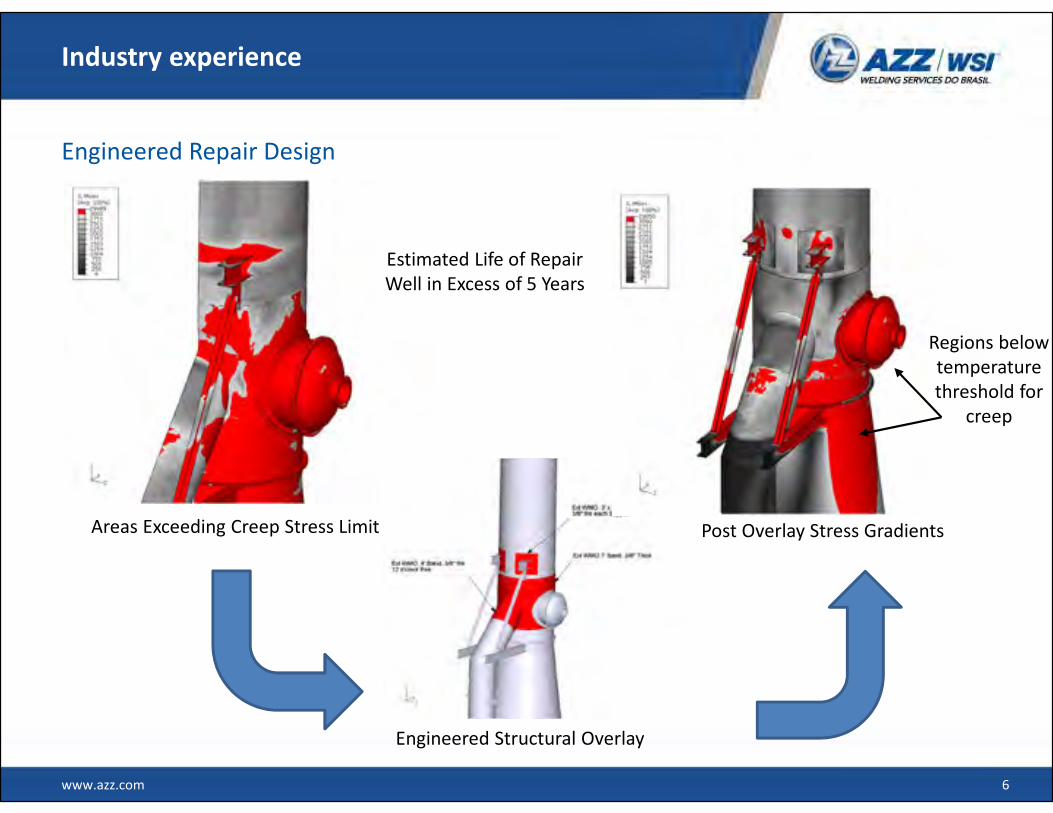
Three Layer Structural Overlay
Finished Structural Overlay
(three layers)

www.azz.com 21
Summary
Results
• Structural Overlay was utilized to repair significant pressure vessel wall thinning.
• A proprietary predictive numerical distortion analysis was used to determine
viability of repair prior to implementation.
• A Fitness for Service analysis was performed per API 579 to qualify the repair.
• Project was performed ahead of estimated schedule with zero safety incidents.
• Project was completed below initial estimated cost.

www.azz.com 22
Contact
Contact Information
Pedro Amador
VP & Chief Technology Officer
+ 1 (678) 728-9100
Norcross, GA, USA