FCC PART 22 and 90 TEST REPORT · DMR Mobile Radio, which was measured ... STM Vehicle Power Cable...
45
Note: This test report is prepared for the customer shown above and for the device described herein. It may not be duplicated or used in part without prior written consent from Bay Area Compliance Laboratories Corp. (Dongguan). This report is valid only with a valid digital signature. The digital signature may be available only under the Adobe software above version 7.0. FCC PART 22 and 90 TEST REPORT For Sepura plc Radio House, St. Andrews Road, Cambridge CB4 1GR UK FCC ID: XX6SEM8050H Report Type: Original Report Product Type: DMR Mobile Radio Test Engineer: Allen Qiao Report Number: RDG150803006-00 Report Date: 2015-11-06 Reviewed By: Sula Huang RF Leader Test Laboratory: Bay Area Compliance Laboratories Corp. (Dongguan) No.69 Pulongcun, Puxinhu Industrial Zone, Tangxia, Dongguan, Guangdong, China Tel: +86-769-86858888 Fax: +86-769-86858891 www.baclcorp.com.cn
Transcript of FCC PART 22 and 90 TEST REPORT · DMR Mobile Radio, which was measured ... STM Vehicle Power Cable...

Note: This test report is prepared for the customer shown above and for the device described herein. It may not be duplicated or used in part without prior written consent from Bay Area Compliance Laboratories Corp. (Dongguan). This report is valid only with a valid digital signature. The digital signature may be available only under the Adobe software above version 7.0.
FCC PART 22 and 90 TEST REPORT
For
Sepura plc
Radio House, St. Andrews Road, Cambridge CB4 1GR UK
FCC ID: XX6SEM8050H
Report Type:
Original Report
Product Type:
DMR Mobile Radio
Test Engineer: Allen Qiao
Report Number:
RDG150803006-00
Report Date:
2015-11-06
Reviewed By:
Sula Huang RF Leader
Test Laboratory:
Bay Area Compliance Laboratories Corp. (Dongguan) No.69 Pulongcun, Puxinhu Industrial Zone, Tangxia, Dongguan, Guangdong, China Tel: +86-769-86858888 Fax: +86-769-86858891 www.baclcorp.com.cn

Bay Area Compliance Laboratories Corp. (Dongguan) Report No.: RDG150803006-00
FCC Part 22 and 90 Page 2 of 45
TABLE OF CONTENTS GENERAL INFORMATION ....................................................................................................................................... 4
PRODUCT DESCRIPTION FOR EQUIPMENT UNDER TEST (EUT) ..................................................................................... 4 OBJECTIVE ................................................................................................................................................................... 4 RELATED SUBMITTAL(S)/GRANT(S) ............................................................................................................................. 4 TEST METHODOLOGY .................................................................................................................................................. 4 TEST FACILITY ............................................................................................................................................................. 4
SYSTEM TEST CONFIGURATION .......................................................................................................................... 5 DESCRIPTION OF TEST CONFIGURATION ...................................................................................................................... 5 EQUIPMENT MODIFICATIONS ....................................................................................................................................... 5 SUPPORT EQUIPMENT LIST AND DETAILS .................................................................................................................... 5 EXTERNAL CABLE ........................................................................................................................................................ 5 BLOCK DIAGRAM OF TEST SETUP ................................................................................................................................ 6
SUMMARY OF TEST RESULTS ............................................................................................................................... 7
FCC §2.1091- MAXIMUM PERMISSIBLE EXPOSURE (MPE) ........................................................................... 8 APPLICABLE STANDARD .............................................................................................................................................. 8
FCC §2.1046 &§ 22.727 & §90.205- RF OUTPUT POWER .................................................................................. 10 APPLICABLE STANDARD ............................................................................................................................................ 10 TEST PROCEDURE ...................................................................................................................................................... 10 TEST EQUIPMENT LIST AND DETAILS ......................................................................................................................... 10 TEST DATA ................................................................................................................................................................ 10
FCC §2.1047 & §90.207 - MODULATION CHARACTERISTIC .......................................................................... 12 APPLICABLE STANDARD ............................................................................................................................................ 12 TEST PROCEDURE ...................................................................................................................................................... 12 TEST EQUIPMENT LIST AND DETAILS ......................................................................................................................... 12 TEST DATA ................................................................................................................................................................ 12
FCC §2.1049& §22.357 & § 22.731 &§90.209 & §90.210 – OCCUPIED BANDWIDTH & EMISSION MASK 18 APPLICABLE STANDARD ............................................................................................................................................ 18 TEST EQUIPMENT LIST AND DETAILS ......................................................................................................................... 19 TEST PROCEDURE ...................................................................................................................................................... 19 TEST DATA ................................................................................................................................................................ 19
FCC §2.1051& §22.861 & §90.210 - SPURIOUS EMISSIONS AT ANTENNA TERMINALS ........................... 27 APPLICABLE STANDARD ............................................................................................................................................ 27 TEST EQUIPMENT LIST AND DETAILS ......................................................................................................................... 27 TEST PROCEDURE ...................................................................................................................................................... 28 TEST DATA ................................................................................................................................................................ 28
FCC §2.1053 & §22.861 & §90.210 - RADIATED SPURIOUS EMISSIONS ........................................................ 33 APPLICABLE STANDARD ............................................................................................................................................ 33 TEST EQUIPMENT LIST AND DETAILS ......................................................................................................................... 33 TEST PROCEDURE ...................................................................................................................................................... 33 TEST DATA ................................................................................................................................................................ 34
FCC §2.1055 & § 22.355 & §90.213- FREQUENCY STABILITY ........................................................................ 37 APPLICABLE STANDARD ............................................................................................................................................ 37
Bay Area Compliance Laboratories Corp. (Dongguan) Report No.: RDG150803006-00
FCC Part 22 and 90 Page 3 of 45
TEST EQUIPMENT LIST AND DETAILS ......................................................................................................................... 37 TEST PROCEDURE ...................................................................................................................................................... 37 TEST DATA ................................................................................................................................................................ 37
FCC §90.214 - TRANSIENT FREQUENCY BEHAVIOR ...................................................................................... 40 APPLICABLE STANDARD ............................................................................................................................................ 40 TEST EQUIPMENT LIST AND DETAILS ......................................................................................................................... 40 TEST PROCEDURE ...................................................................................................................................................... 40 TEST DATA ................................................................................................................................................................ 41

Bay Area Compliance Laboratories Corp. (Dongguan) Report No.: RDG150803006-00
FCC Part 22 and 90 Page 4 of 45
GENERAL INFORMATION Product Description for Equipment under Test (EUT) The Sepura plc’s product, model: SEM8050H (FCC ID: XX6SEM8050H) (the "EUT") in this report is a DMR Mobile Radio, which was measured approximately: 17.8 cm (L) x 19.5 cm (W) x 5.8 cm (H), rated input voltage: 13.6VDC or 15VDC powered from AC/DC adapter. Adapter information: Model: GS220A15 Input: AC100-240V, 50/60Hz, 4.0A Output: DC 15V, 13.4A, 201W max * All measurement and test data in this report was gathered from production sample serial number: 7PR031530GD0223(Assigned by Applicant). The EUT was received on 2015-08-12.
Objective This test report is prepared on behalf of Sepura plc in accordance with Part 2, Part 22 and Part 90 of the Federal Communications Commission rules. Related Submittal(s)/Grant(s) No related submittal(s). Test Methodology All tests and measurements indicated in this document were performed in accordance with the Code of federal Regulations Title 47 Part 2, Sub-part J as well as the following individual parts: Part 22 – Public Mobile Service Part 90 – Private Land Mobile Radio Service Applicable Standards: TIA 603-D and ANSI 63.4-2009. All emissions measurement was performed and Bay Area Compliance Laboratories Corp. (Dongguan). The radiated testing was performed at an antenna-to-EUT distance of 3 meters. Test Facility The Test site used by Bay Area Compliance Laboratories Corp. (Dongguan) to collect test data is located on the No.69 Pulongcun, Puxinhu Industrial Zone, Tangxia, Dongguan, Guangdong, China Test site at Bay Area Compliance Laboratories Corp. (Dongguan) has been fully described in reports submitted to the Federal Communications Commission (FCC). The details of these reports have been found to be in compliance with the requirements of Section 2.948 of the FCC Rules on February 06, 2015. The facility also complies with the radiated and AC line conducted test site criteria set forth in ANSI C63.4-2009. The Federal Communications Commission has the reports on file and is listed under FCC Registration No.: 273710. The test site has been approved by the FCC for public use and is listed in the FCC Public Access Link (PAL) database.

Bay Area Compliance Laboratories Corp. (Dongguan) Report No.: RDG150803006-00
FCC Part 22 and 90 Page 5 of 45
SYSTEM TEST CONFIGURATION Description of Test Configuration The system was configured for testing in a test mode. EUT Specification:
Operating Frequency Band 450-520 MHz Modulation Mode FM/4FSK Channel Spacing 12.5 kHz
Rated Output Power High power level: 40W Low power level: 25W
Equipment Modifications No modifications were made to the unit tested. Support Equipment List and Details
External Cable
Cable Description Shielding
Type Ferrite Core
Length (m)
From Port To
DC Cable no no 5.0 Connector DC power supply
Adapter Cable no no 1.5 Adapter EUT
Manufacturer Description Model Serial Number
Desktop
MEAN WELL Desktop PSUincludes adaptor cable GS220A15 EB42200946
Sepura Desk Mounting bracket 300-01063 / Sepura DDM(Desktop Mic with PTT) 300-01065 / Sepura USB Data Lead 300-01164 / Sepura Programming Cable 300-01075 /
Vehicle Installation Pro instrument DC Power Supply pps3300 N/A
Sepura STM(Std. Fist Mic.) 300-01077 7PR201530D30201 Sepura Keypad Mic 300-01064 / Sepura I/O Interface lead 300-01165 / Sepura Vehicle Power Cable 300-01066 / Sepura Programming Cable 300-01075 /

Bay Area Compliance Laboratories Corp. (Dongguan) Report No.: RDG150803006-00
FCC Part 22 and 90 Page 6 of 45
Block Diagram of Test Setup Vehicle Installation Desktop
1.0 Meter
1.5 Meter
50 Ω Load
Non-conductive table 80 cm above Ground Plane
Non-conductive table 150 cm above Ground Plane
Non-conductive table 150 cm above Ground Plane
EUT
13.6VDC
STM
Vehicle Power CableVehicle Power Cable
I/O Interface leadI/O Interface lead
1.0 Meter
1.5 Meter
50 Ω Load
Non-conductive table 80 cm above Ground Plane
Non-conductive table 150 cm above Ground Plane
Non-conductive table 150 cm above Ground Plane
EUT
AC/DC adapter
120VAC/60 Hz
DDM
USB data leadUSB data lead

Bay Area Compliance Laboratories Corp. (Dongguan) Report No.: RDG150803006-00
FCC Part 22 and 90 Page 7 of 45
SUMMARY OF TEST RESULTS
FCC Rules Description of Test Results
§2.1091 Maximum Permissible Exposure Compliance
§2.1046; § 22.727;§90.205 RF Output Power Compliance
§2.1047;§90.207 Modulation Characteristic Compliance
§2.1049;§22.357;§ 22.731;§90.209; §90.210 Occupied Bandwidth & Emission Mask Compliance
§2.1051; §22.861;§90.210 Spurious Emission at Antenna Terminal Compliance
§2.1053; §22.861;§90.210 Spurious Radiated Emissions Compliance
§2.1055; § 22.355;§90.213 Frequency Stability Compliance
§90.214 Transient Frequency Behavior Compliance

Bay Area Compliance Laboratories Corp. (Dongguan) Report No.: RDG150803006-00
FCC Part 22 and 90 Page 8 of 45
FCC §2.1091- MAXIMUM PERMISSIBLE EXPOSURE (MPE) Applicable Standard According to 1.1307 (b)(1), 2.1091 systems operating under the provisions of this section shall be operated in a manner that ensures the public is not exposed to RF energy level in excess of the communication guidelines.
Limits for Maximum Permissible Exposure (MPE)
Limits for Occupational/Controlled Exposure
Frequency Range (MHz)
Electric Field Strength (E) (V/m)
Magnetic Field Strength (H) (A/m)
Power Density (S) (mW/cm2)
Averaging Time |E|, |H| or S
(minutes)
0.3- 3.0 614 1.63 (100)* 6
3.0 - 30 1842/f 4.89/f (900/f2)* 6
30-300 61.4 0.163 1.0 6
300-1500 / / f/300 6
1500-100,000 / / 5 6
f = frequency in MHz; * = Plane-wave equivalent power density; MPE Calculation Predication of MPE limit at a given distance
S = PG/4πR2 Where: S = power density (in appropriate units, e.g. mW/cm2);
P = power input to the antenna (in appropriate units, e.g., mW); G = power gain of the antenna in the direction of interest relative to an isotropic radiator R = distance to the center of radiation of the antenna (appropriate units, e.g., cm);

Bay Area Compliance Laboratories Corp. (Dongguan) Report No.: RDG150803006-00
FCC Part 22 and 90 Page 9 of 45
Calculated Data:
Frequency
Max Target Output Power
Duty Cycle
Antenna Cable Loss
Typical Antenna Gain Distance Power
Density Limit
MHz mW dB dBi numeric cm mW/cm2 mW/cm2
450.0125 44668 50% 0 0 1.0 120 0.123 1.50 Note1: The manufacturer does not specify an antenna to be used with this device, but a typical installation has a gain up to 0 dBi. Note2: The maximum tune-up tolerance limit is 40W (46.0 dBm) ±0.5dB = 44668 mW (46.5dBm) Radio Exposure Statement:
Using the parameters given in the above calculation, a minimum antenna to person distance of 120 cm is required to meet the limits for occupational/controlled exposure.
Result: Compliant.

Bay Area Compliance Laboratories Corp. (Dongguan) Report No.: RDG150803006-00
FCC Part 22 and 90 Page 10 of 45
FCC §2.1046 &§ 22.727 & §90.205- RF OUTPUT POWER Applicable Standard FCC §2.1046, § 22.727 and §90.205. Test Procedure Conducted RF Output Power: TIA-603-D section 2.2.1 The RF output of the transmitter was connected to the input of the spectrum analyzer through sufficient attenuation. Spectrum Analyzer setting:
RBW VBW
100 kHz 300 kHz
Test Equipment List and Details
Manufacturer Description Model No. Serial No. Calibration Date
Calibration Due Date
R&S Spectrum Analyzer FSP 38 100478 2015-05-09 2016-05-09
AA-MCS Attenuator(40dB) CAT-50-40-200-Nm-Nf 0602-010 2015-05-08 2016-05-08
E-Microwave DC Blocking EMDCB-00036 0E01201047 2015-05-06 2016-05-06
Pasternack RF Coaxial Cable RF-01 / 2015-05-06 2016-05-06
* Statement of Traceability: Bay Area Compliance Laboratories Corp. (Dongguan) attests that all calibrations have been performed, traceable to National Primary Standards and International System of Units (SI).
Test Data
Environmental Conditions
Temperature: 27.1 °C Relative Humidity: 58 %
ATM Pressure: 100kPa The testing was performed by Allen Qiao on 2015-08-25.

Bay Area Compliance Laboratories Corp. (Dongguan) Report No.: RDG150803006-00
FCC Part 22 and 90 Page 11 of 45
Test Result: Compliance. Please refer to following tables. FCC Part 90:
Modulation mode
Channel Spacing (kHz)
fc (MHz)
Conducted Output Power
(W)
Note High Low
FM
12.5
450.0125 39.99 24.98 /
485 40.06 24.93 /
519.9875 39.92 24.95 Not for FCC Review
4FSK
450.0125 39.95 24.97 /
485 40.04 24.91 /
519.9875 40.00 24.94 Not for FCC Review
FCC Part 22:
Modulation mode
Channel Spacing (kHz)
fc (MHz)
Conducted Output Power
(W) High Low
FM 12.5 kHz
454.0125 39.96 24.97
4FSK 454.0125 39.98 24.92
Bay Area Compliance Laboratories Corp. (Dongguan) Report No.: RDG150803006-00
FCC Part 22 and 90 Page 12 of 45
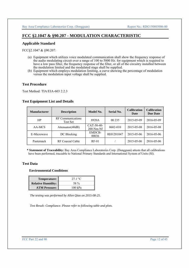
FCC §2.1047 & §90.207 - MODULATION CHARACTERISTIC Applicable Standard FCC§2.1047 & §90.207:
(a) Equipment which utilizes voice modulated communication shall show the frequency response of the audio modulating circuit over a range of 100 to 5000 Hz. for equipment which is required to have a low pass filter, the frequency response of the filter, or all of the circuitry installed between the modulation limited and the modulated stage shall be supplied.
(b) Equipment which employs modulation limiting, a curve showing the percentage of modulation versus the modulation input voltage shall be supplied.
Test Procedure Test Method: TIA/EIA-603 2.2.3 Test Equipment List and Details
Manufacturer Description Model No. Serial No. Calibration Date
Calibration Due Date
HP RF Communications Test Set 8920A 00 235 2015-05-09 2016-05-09
AA-MCS Attenuator(40dB) CAT-50-40-200-Nm-Nf 0602-010 2015-05-08 2016-05-08
E-Microwave DC Blocking EMDCB-00036 0E01201047 2015-05-06 2016-05-06
Pasternack RF Coaxial Cable RF-01 / 2015-05-06 2016-05-06
* Statement of Traceability: Bay Area Compliance Laboratories Corp. (Dongguan) attests that all calibrations have been performed, traceable to National Primary Standards and International System of Units (SI).
Test Data
Environmental Conditions
Temperature: 27.1 °C Relative Humidity: 58 %
ATM Pressure: 100 kPa The testing was performed by Allen Qiao on 2015-08-25.
Test Result: Compliance. Please refer to following table and plots.

Bay Area Compliance Laboratories Corp. (Dongguan) Report No.: RDG150803006-00
FCC Part 22 and 90 Page 13 of 45
MODULATION LIMITING
Carrier Frequency: 485MHz, Channel Spacing= 12.5 kHz, high power level
AUDIO INPUT LEVEL
DEVIATION (@300Hz)
DEVIATION (@ 1kHz)
DEVIATION (@ 3kHz) Limit
dBµV kHz kHz kHz kHz 100.5 2.259 2.239 1.951 2.5 95.5 2.251 2.235 1.955 2.5 90.5 1.436 2.238 1.951 2.5 85.5 0.853 2.225 1.951 2.5 80.5 0.493 1.500 1.961 2.5 75.5 0.310 0.889 1.753 2.5 70.5 0.202 0.522 1.016 2.5 65.5 0.137 0.323 0.585 2.5 60.5 0.112 0.213 0.351 2.5

Bay Area Compliance Laboratories Corp. (Dongguan) Report No.: RDG150803006-00
FCC Part 22 and 90 Page 14 of 45
Carrier Frequency: 485MHz, Channel Spacing= 12.5 kHz, low power level
AUDIO INPUT LEVEL
DEVIATION (@300Hz)
DEVIATION (@ 1kHz)
DEVIATION (@ 3kHz) Limit
dBµV kHz kHz kHz kHz 100.5 2.279 2.239 1.971 2.5 95.5 2.171 2.275 2.045 2.5 90.5 1.476 2.288 1.911 2.5 85.5 0.813 2.195 1.871 2.5 80.5 0.503 1.500 2.021 2.5 75.5 0.320 0.969 1.693 2.5 70.5 0.152 0.612 1.016 2.5 65.5 0.187 0.303 0.605 2.5 60.5 0.142 0.153 0.291 2.5

Bay Area Compliance Laboratories Corp. (Dongguan) Report No.: RDG150803006-00
FCC Part 22 and 90 Page 15 of 45
Audio Frequency Response
Carrier Frequency: 485 MHz, Channel Spacing= 12.5 kHz, high power level
Audio Frequency
Response Attenuation
Hz dB 300 -10.25 400 -7.83 500 -6.27 600 -5.11 700 -4.02 800 -2.75 900 -1.26 1000 0.00 1200 1.75 1400 3.22 1600 4.40 1800 4.25 2000 4.43 2200 5.35 2400 5.83 2600 6.53 2800 7.38 3000 6.58

Bay Area Compliance Laboratories Corp. (Dongguan) Report No.: RDG150803006-00
FCC Part 22 and 90 Page 16 of 45
Audio Frequency Response
Carrier Frequency: 485MHz, Channel Spacing= 12.5 kHz, low power level
Audio Frequency
Response Attenuation
Hz dB 300 -10.16 400 -8.06 500 -5.82 600 -4.94 700 -3.58 800 -2.49 900 -1.02 1000 0.00 1200 1.76 1400 3.12 1600 4.17 1800 4.50 2000 4.44 2200 5.09 2400 5.73 2600 6.37 2800 7.29 3000 6.80

Bay Area Compliance Laboratories Corp. (Dongguan) Report No.: RDG150803006-00
FCC Part 22 and 90 Page 17 of 45
Audio Frequency Low Pass Filter Response
Carrier Frequency: 485 MHz, Channel Spacing= 12.5 kHz, high power level
Audio
Frequency Response
Attenuation Limit
kHz dB dB 3.0 -1.3 0.0 3.5 -11.3 -6.7 4.0 -19.0 -12.5 5.0 -28.4 -22.2 7.0 -45.3 -36.8
10.0 -59.8 -52.3 15.0 -78.3 -69.9 20.0 -84.3 -82.5 30.0 -84.0 -82.5 50.0 -84.1 -82.5 70.0 -85.0 -82.5

Bay Area Compliance Laboratories Corp. (Dongguan) Report No.: RDG150803006-00
FCC Part 22 and 90 Page 18 of 45
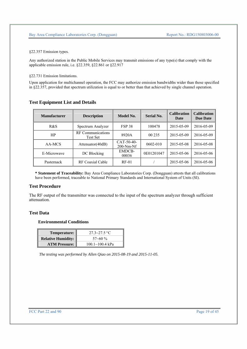
FCC §2.1049& §22.357 & § 22.731 &§90.209 & §90.210 – OCCUPIED BANDWIDTH & EMISSION MASK Applicable Standard FCC §2.1049, §22.357, § 22.731, §90.209 and §90.210
Applicable Emission Masks
Frequency band (MHz) Mask for equipment
with audio low pass filter
Mask for equipment without audio low
pass filter Below 25 A or B A or C
25-50 B C 72-76 B C
150-174 B, D, or E C, D or E 150 paging only B C
220-222 F F 421-512 B, D, or E C, D, or E
450 paging only B G 806-809/851-854 B H 809-824/854-869 B G 896-901/935-940 I J
902-928 K K 929-930 B G
4940-4990 MHz L or M L or M 5850-5925
All other bands B C
Emission Mask D—12.5 kHz channel bandwidth equipment. For transmitters designed to operate with a 12.5 kHz channel bandwidth, any emission must be attenuated below the power (P) of the highest emission contained within the authorized bandwidth as follows:
(1) On any frequency from the center of the authorized bandwidth f0 to 5.625 kHz removed from f0: Zero dB.
(2) On any frequency removed from the center of the authorized bandwidth by a displacement frequency (fd in kHz) of more than 5.625 kHz but no more than 12.5 kHz: At least 7.27(fd−2.88 kHz) dB.
(3) On any frequency removed from the center of the authorized bandwidth by a displacement frequency (fd in kHz) of more than 12.5 kHz: At least 50 + 10 log (P) dB or 70 dB, whichever is the lesser attenuation.
(4) The reference level for showing compliance with the emission mask shall be established using a resolution bandwidth sufficiently wide (usually two or three times the channel bandwidth) to capture the true peak emission of the equipment under test. In order to show compliance with the emission mask up to and including 50 kHz removed from the edge of the authorized bandwidth, adjust the resolution bandwidth to 100 Hz with the measuring instrument in a peak hold mode. A sufficient number of sweeps must be measured to insure that the emission profile is developed. If video filtering is used, its bandwidth must not be less than the instrument resolution bandwidth. For emissions beyond 50 kHz from the edge of the authorized bandwidth, see paragraph (o) of this section. If it can be shown that use of the above instrumentation settings do not accurately represent the true interference potential of the equipment under test, an alternate procedure may be used provided prior Commission approval is obtained.
Bay Area Compliance Laboratories Corp. (Dongguan) Report No.: RDG150803006-00
FCC Part 22 and 90 Page 19 of 45
§22.357 Emission types.
Any authorized station in the Public Mobile Services may transmit emissions of any type(s) that comply with the applicable emission rule, i.e. §22.359, §22.861 or §22.917 §22.731 Emission limitations. Upon application for multichannel operation, the FCC may authorize emission bandwidths wider than those specified in §22.357, provided that spectrum utilization is equal to or better than that achieved by single channel operation. Test Equipment List and Details
Manufacturer Description Model No. Serial No. Calibration Date
Calibration Due Date
R&S Spectrum Analyzer FSP 38 100478 2015-05-09 2016-05-09
HP RF Communications Test Set 8920A 00 235 2015-05-09 2016-05-09
AA-MCS Attenuator(40dB) CAT-50-40-200-Nm-Nf 0602-010 2015-05-08 2016-05-08
E-Microwave DC Blocking EMDCB-00036 0E01201047 2015-05-06 2016-05-06
Pasternack RF Coaxial Cable RF-01 / 2015-05-06 2016-05-06
* Statement of Traceability: Bay Area Compliance Laboratories Corp. (Dongguan) attests that all calibrations have been performed, traceable to National Primary Standards and International System of Units (SI).
Test Procedure The RF output of the transmitter was connected to the input of the spectrum analyzer through sufficient attenuation. Test Data
Environmental Conditions
Temperature: 27.3~27.5 °C Relative Humidity: 57~60 %
ATM Pressure: 100.1~100.4 kPa The testing was performed by Allen Qiao on 2015-08-19 and 2015-11-05.

Bay Area Compliance Laboratories Corp. (Dongguan) Report No.: RDG150803006-00
FCC Part 22 and 90 Page 20 of 45
Test Result: Compliance. Please refer to the following tables and plots.
FCC Part 90:
Modulation Mode
Channel Spacing fc
26 dB Bandwidth
99% Bandwidth Power
Level kHz MHz kHz kHz
FM
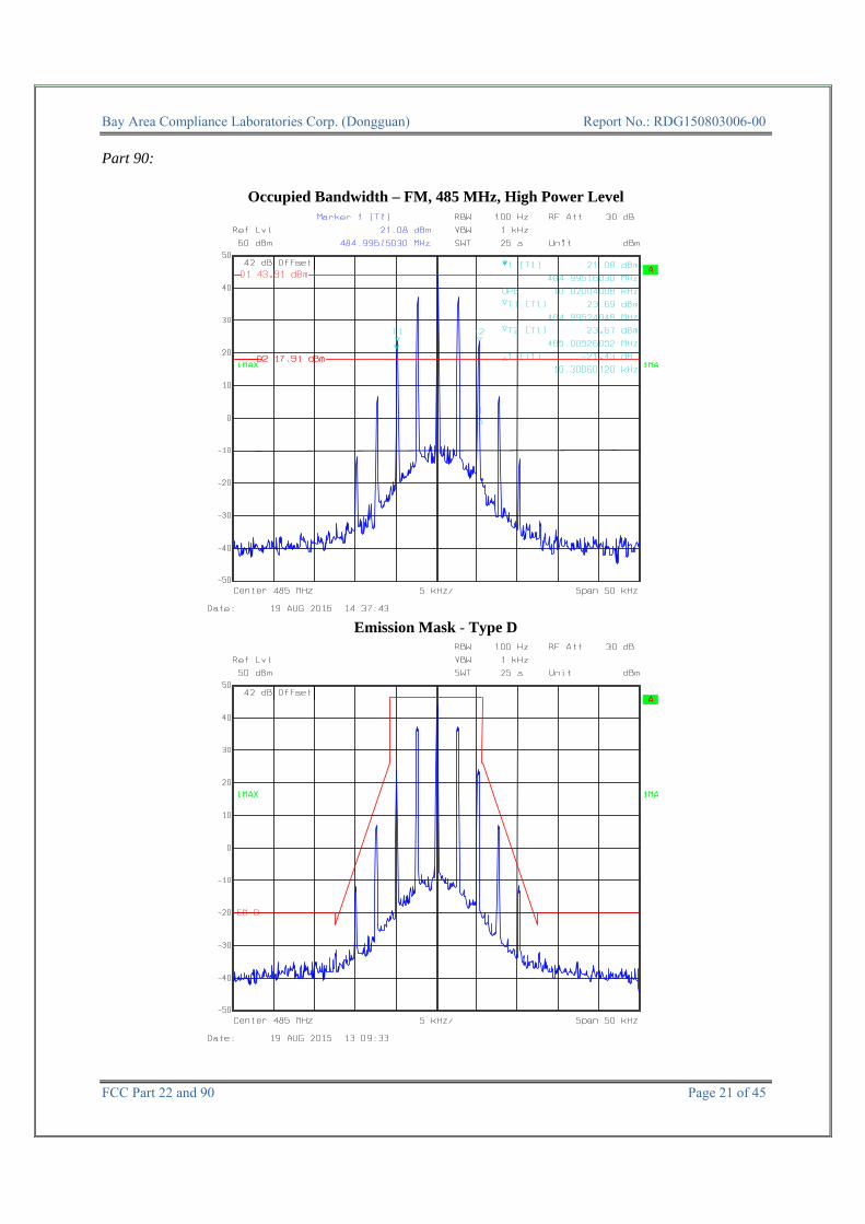
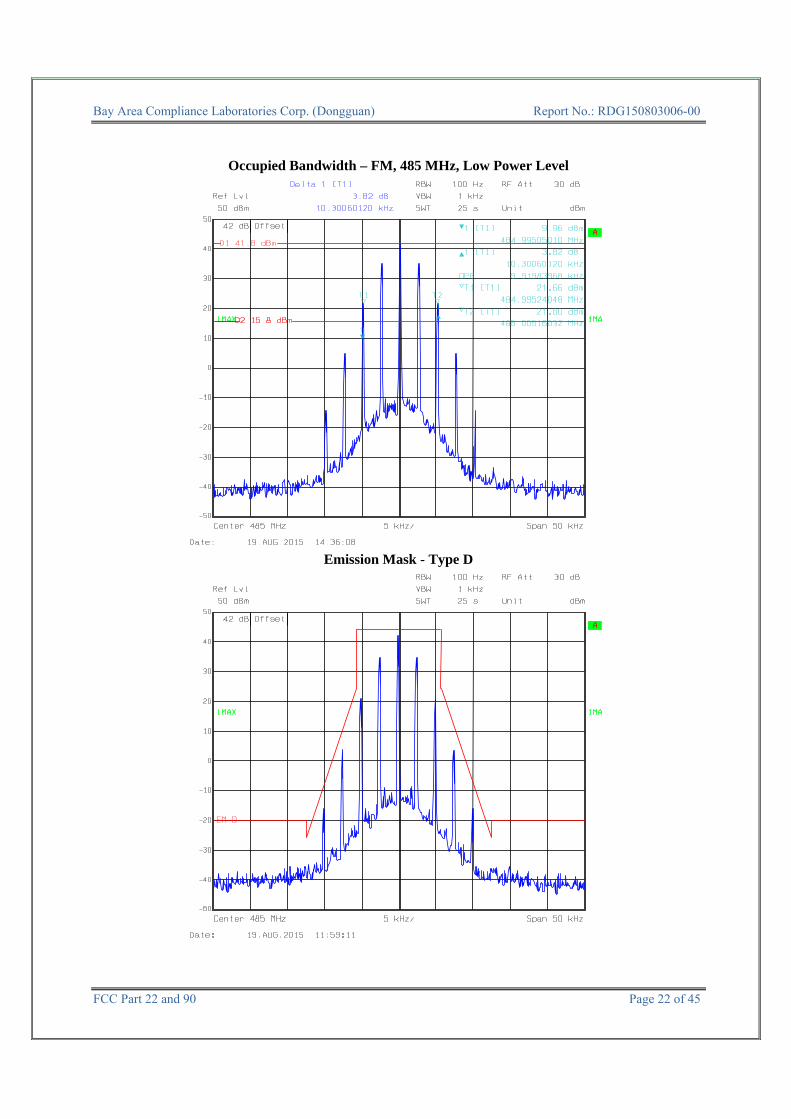
12.5 485
10.30 10.02 High
4FSK 9.70 7.31 FM 10.30 9.92
Low 4FSK 9.10 7.11
FCC Part 22:
Modulation Mode
Channel Spacing fc
26 dB Bandwidth
99% Bandwidth Power
Level kHz MHz kHz kHz
FM
12.5 454.0125
10.31 9.92 High
4FSK 9.05 7.31 FM 10.31 9.92
Low 4FSK 9.62 7.31
Note: Emission bandwidth was based on calculation method instead of measurement. Per CFR 47 §2.201& §2.202&, Bn = 2M + 2D For FM Mode (Channel Spacing: 12.5 kHz) Emission Designator 11K0F3E In this case, the maximum modulating frequency is 3.0 kHz with a 2.5 kHz deviation. BW = 2(M+D) = 2*(3.0 kHz + 2.5 kHz) = 11 kHz = 11K0 F3E portion of the designator represents an FM voice transmission Therefore, the entire designator for 12.5 kHz channel spacing FM mode is 11K0F3E. For Digital Mode (Channel Spacing: 12.5 kHz) Emission Designator 7K60FXD and 7K60FXW The 99% energy rule (title 47CFR 2.1049) was used for digital mode. It basically states that 99% of the modulation energy falls within X kHz, in this case, 7.31 kHz. The emission mask was obtained from 47CFR 90.210(d). FXD and FXW portion of the designator indicates digital information. Therefore, the entire designator for 12.5 kHz channel spacing digital mode is 7K60FXD and 7K60FXW.
Bay Area Compliance Laboratories Corp. (Dongguan) Report No.: RDG150803006-00
FCC Part 22 and 90 Page 21 of 45
Part 90:
Occupied Bandwidth – FM, 485 MHz, High Power Level
Emission Mask - Type D
Bay Area Compliance Laboratories Corp. (Dongguan) Report No.: RDG150803006-00
FCC Part 22 and 90 Page 22 of 45
Occupied Bandwidth – FM, 485 MHz, Low Power Level
Emission Mask - Type D

Bay Area Compliance Laboratories Corp. (Dongguan) Report No.: RDG150803006-00
FCC Part 22 and 90 Page 23 of 45
Occupied Bandwidth –4FSK, 485 MHz, High Power Level
Emission Mask - Type D

Bay Area Compliance Laboratories Corp. (Dongguan) Report No.: RDG150803006-00
FCC Part 22 and 90 Page 24 of 45
Occupied Bandwidth – 4FSK, 485 MHz, Low Power Level
Emission Mask - Type D

Bay Area Compliance Laboratories Corp. (Dongguan) Report No.: RDG150803006-00
FCC Part 22 and 90 Page 25 of 45
Part 22:
Occupied Bandwidth – FM, 454.0125MHz, High Power Level
Occupied Bandwidth – FM, 454.0125 MHz, Low Power Level

Bay Area Compliance Laboratories Corp. (Dongguan) Report No.: RDG150803006-00
FCC Part 22 and 90 Page 26 of 45
Occupied Bandwidth –4FSK, 454.0125 MHz, High Power Level
Occupied Bandwidth – 4FSK, 454.0125 MHz, Low Power Level

Bay Area Compliance Laboratories Corp. (Dongguan) Report No.: RDG150803006-00
FCC Part 22 and 90 Page 27 of 45
FCC §2.1051& §22.861 & §90.210 - SPURIOUS EMISSIONS AT ANTENNA TERMINALS Applicable Standard
Emission Mask D—12.5 kHz channel bandwidth equipment. For transmitters designed to operate with a 12.5 kHz channel bandwidth, any emission must be attenuated below the power (P) of the highest emission contained within the authorized bandwidth as follows:
(1) On any frequency from the center of the authorized bandwidth f0 to 5.625 kHz removed from f0: Zero dB.
(2) On any frequency removed from the center of the authorized bandwidth by a displacement frequency (fd in kHz) of more than 5.625 kHz but no more than 12.5 kHz: At least 7.27(fd−2.88 kHz) dB.
(3) On any frequency removed from the center of the authorized bandwidth by a displacement frequency (fd in kHz) of more than 12.5 kHz: At least 50 + 10 log (P) dB or 70 dB, whichever is the lesser attenuation.
(4) The reference level for showing compliance with the emission mask shall be established using a resolution bandwidth sufficiently wide (usually two or three times the channel bandwidth) to capture the true peak emission of the equipment under test. In order to show compliance with the emission mask up to and including 50 kHz removed from the edge of the authorized bandwidth, adjust the resolution bandwidth to 100 Hz with the measuring instrument in a peak hold mode. A sufficient number of sweeps must be measured to insure that the emission profile is developed. If video filtering is used, its bandwidth must not be less than the instrument resolution bandwidth. For emissions beyond 50 kHz from the edge of the authorized bandwidth, see paragraph (o) of this section. If it can be shown that use of the above instrumentation settings do not accurately represent the true interference potential of the equipment under test, an alternate procedure may be used provided prior Commission approval is obtained.
§22.861 Emission limitations. (a) Out of band emissions. The power of any emission outside of the authorized operating frequency ranges must be
attenuated below the transmitting power (P) by a factor of at least 43 + 10 log (P) dB. Test Equipment List and Details
Manufacturer Description Model No. Serial No. Calibration Date
Calibration Due Date
R&S Spectrum Analyzer FSP 38 100478 2015-05-09 2016-05-09
HP RF Communications Test Set 8920A 00 235 2015-05-09 2016-05-09
AA-MCS Attenuator(40dB) CAT-50-40-200-Nm-Nf 0602-010 2015-05-08 2016-05-08
E-Microwave DC Blocking EMDCB-00036 0E01201047 2015-05-06 2016-05-06
Mini-Circuits HIGH PASS FILTER BHP-550+ YZU15801121 2015-05-06 2016-05-06
Pasternack RF Coaxial Cable RF-01 / 2015-05-06 2016-05-06
* Statement of Traceability: Bay Area Compliance Laboratories Corp. (Dongguan) attests that all calibrations have been performed, traceable to National Primary Standards and International System of Units (SI).

Bay Area Compliance Laboratories Corp. (Dongguan) Report No.: RDG150803006-00
FCC Part 22 and 90 Page 28 of 45
Test Procedure Adjust the spectrum analyzer for the following settings: 1) Resolution Bandwidth = 100 kHz for spurious emissions below 1 GHz, and 1 MHz for spurious
emissions above 1 GHz. 2) Video Bandwidth ≥3 times the resolution bandwidth. 3) Sweep Speed ≤2000 Hz per second. 4) Detector Mode = mean or average power. Test Data
Environmental Conditions
Temperature: 27.3 °C Relative Humidity: 59 %
ATM Pressure: 100.2 kPa The testing was performed by Allen Qiao on 2015-08-18.

Bay Area Compliance Laboratories Corp. (Dongguan) Report No.: RDG150803006-00
FCC Part 22 and 90 Page 29 of 45
FCC PART 90
485MHz – FM Mode,High Power
Fundamental test with Band Reject Filter

Bay Area Compliance Laboratories Corp. (Dongguan) Report No.: RDG150803006-00
FCC Part 22 and 90 Page 30 of 45
FCC PART 90485 MHz –4FSK Mode,High Power
Fundamental test with Band Reject Filter
Bay Area Compliance Laboratories Corp. (Dongguan) Report No.: RDG150803006-00
FCC Part 22 and 90 Page 31 of 45
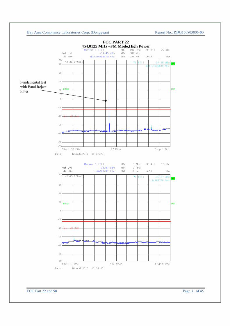
FCC PART 22
454.0125 MHz –FM Mode,High Power
Fundamental test with Band Reject Filter
Bay Area Compliance Laboratories Corp. (Dongguan) Report No.: RDG150803006-00
FCC Part 22 and 90 Page 32 of 45
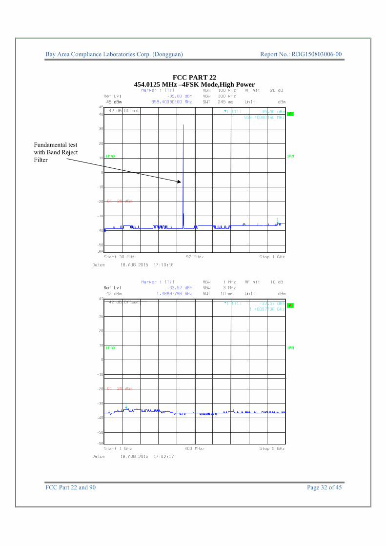
FCC PART 22454.0125 MHz –4FSK Mode,High Power
Fundamental test with Band Reject Filter
Bay Area Compliance Laboratories Corp. (Dongguan) Report No.: RDG150803006-00
FCC Part 22 and 90 Page 33 of 45
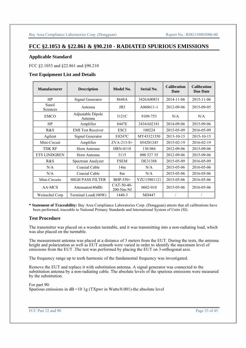
FCC §2.1053 & §22.861 & §90.210 - RADIATED SPURIOUS EMISSIONS Applicable Standard FCC §2.1053 and §22.861 and §90.210 Test Equipment List and Details
Manufacturer Description Model No. Serial No. Calibration Date
Calibration Due Date
HP Signal Generator 8648A 3426A00831 2014-11-06 2015-11-06 Sunol
Sciences Antenna JB3 A060611-1 2012-09-06 2015-09-05
EMCO Adjustable Dipole Antenna 3121C 9109-753 N/A N/A
HP Amplifier 8447E 2434A02181 2014-09-06 2015-09-06 R&S EMI Test Receiver ESCI 100224 2015-05-09 2016-05-09
Agilent Signal Generator E8247C MY43321350 2013-10-15 2015-10-15 Mini-Circuit Amplifier ZVA-213-S+ 054201245 2015-02-19 2016-02-19
TDK RF Horn Antenna HRN-0118 130 084 2012-09-06 2015-09-06 ETS LINDGREN Horn Antenna 3115 000 527 35 2012-09-06 2015-09-06
R&S Spectrum Analyzer FSEM DE31388 2015-05-09 2016-05-09 N/A Coaxial Cable 14m N/A 2015-05-06 2016-05-06 N/A Coaxial Cable 8m N/A 2015-05-06 2016-05-06
Mini-Circuits HIGH PASS FILTER BHP-550+ YZU15801121 2015-05-06 2016-05-06
AA-MCS Attenuator(40dB) CAT-50-40-200-Nm-Nf 0602-010 2015-05-06 2016-05-06
Weinschel Corp Terminal Load(100W) 1440-3 MD447 / / * Statement of Traceability: Bay Area Compliance Laboratories Corp. (Dongguan) attests that all calibrations have
been performed, traceable to National Primary Standards and International System of Units (SI). Test Procedure The transmitter was placed on a wooden turntable, and it was transmitting into a non-radiating load, which was also placed on the turntable. The measurement antenna was placed at a distance of 3 meters from the EUT. During the tests, the antenna height and polarization as well as EUT azimuth were varied in order to identify the maximum level of emissions from the EUT .The test was performed by placing the EUT on 3-orthogonal axis. The frequency range up to teeth harmonic of the fundamental frequency was investigated. Remove the EUT and replace it with substitution antenna. A signal generator was connected to the substitution antenna by a non-radiating cable. The absolute levels of the spurious emissions were measured by the substitution. For part 90: Spurious emissions in dB =10 1g (TXpwr in Watts/0.001)-the absolute level

Bay Area Compliance Laboratories Corp. (Dongguan) Report No.: RDG150803006-00
FCC Part 22 and 90 Page 34 of 45
Spurious attenuation limit in dB =50+10 Log10 (power out in Watts) for EUT with a 12.5 kHz channel bandwidth. For part 22: The power of any emission outside of the authorized operating frequency ranges must be attenuated below the transmitting power (P) by a factor of at least 43 + 10 log (P) dB. Test Data
Environmental Conditions
Temperature: 27.3°C Relative Humidity: 57 %
ATM Pressure: 98.9kPa The testing was performed by Allen Qiao on 2015-08-13..
Test Mode: Transmitting (FM mode, high power level, powered from 13.6VDC)
Frequency (MHz)
Polar (H/V)
Receiver Reading (dBµV)
Substituted Method Absolute
Level (dBm)
Limit (dBm)
Margin (dB)
S.G. Level (dBm)
Antenna Gain
(dBd/dBi)
Cable Loss (dB)
Frequency: 485.000 MHz for FCC PART 90 1455.000 H 34.30 -66.8 9.3 1.3 -58.8 -20.0 38.8 1455.000 V 33.62 -67.5 9.3 1.3 -59.5 -20.0 39.5 1940.000 H 33.18 -65.6 11.9 1.4 -55.1 -20.0 35.1 1940.000 V 32.68 -65.3 11.9 1.4 -54.8 -20.0 34.8 970.000 H 40.19 -50 0.0 1.0 -51.0 -20.0 31.0 970.000 V 37.67 -54.1 0.0 1.0 -55.1 -20.0 35.1
Frequency: 454.0125 MHz for FCC PART 22 1362.038 H 34.59 -65.8 8.7 1.4 -58.5 -13.0 45.5 1362.038 V 33.41 -66.9 8.7 1.4 -59.6 -13.0 46.6 1816.050 H 34.94 -65.1 11.2 1.3 -55.2 -13.0 42.2 1816.050 V 34.37 -65.9 11.2 1.3 -56.0 -13.0 43.0 908.025 H 45.84 -46.8 0.0 1 -47.8 -13.0 34.8 908.025 V 35.78 -58.8 0.0 1 -59.8 -13.0 46.8

Bay Area Compliance Laboratories Corp. (Dongguan) Report No.: RDG150803006-00
FCC Part 22 and 90 Page 35 of 45
Test Mode: Transmitting (FSK mode, high power level, powered from 13.6VDC)
Frequency (MHz)
Polar (H/V)
Receiver Reading (dBµV)
Substituted Method Absolute
Level (dBm)
Limit (dBm)
Margin (dB)
S.G. Level (dBm)
Antenna Gain
(dBd/dBi)
Cable Loss (dB)
Frequency: 485.000 MHz for FCC PART 90 1455.000 H 36.60 -64.5 9.3 1.3 -56.5 -20.0 36.5 1455.000 V 35.58 -65.6 9.3 1.3 -57.6 -20.0 37.6 1940.000 H 34.82 -64 11.9 1.4 -53.5 -20.0 33.5 1940.000 V 34.42 -63.5 11.9 1.4 -53.0 -20.0 33.0 970.000 H 49.10 -41.1 0.0 1 -42.1 -20.0 22.1 970.000 V 37.95 -53.8 0.0 1 -54.8 -20.0 34.8
Frequency: 454.0125 MHz for FCC PART 22 1362.038 H 35.84 -64.5 8.7 1.4 -57.2 -13.0 44.2 1362.038 V 34.13 -66.2 8.7 1.4 -58.9 -13.0 45.9 1816.050 H 36.14 -63.9 11.2 1.3 -54.0 -13.0 41.0 1816.050 V 35.13 -65.2 11.2 1.3 -55.3 -13.0 42.3 908.025 H 38.27 -54.4 0.0 1 -55.4 -13.0 42.4 908.025 V 38.40 -56.2 0.0 1 -57.2 -13.0 44.2
Test Mode: Transmitting (FM mode, high power level, powered from AC/DC Adapter)
Frequency (MHz)
Polar (H/V)
Receiver Reading (dBµV)
Substituted Method Absolute
Level (dBm)
Limit (dBm)
Margin (dB)
S.G. Level (dBm)
Antenna Gain
(dBd/dBi)
Cable Loss (dB)
Frequency: 485.000 MHz for FCC PART 90 1455.000 H 34.80 -66.3 9.3 1.3 -58.3 -20.0 38.3 1455.000 V 33.95 -67.2 9.3 1.3 -59.2 -20.0 39.2 1940.000 H 33.58 -65.2 11.9 1.4 -54.7 -20.0 34.7 1940.000 V 33.03 -64.9 11.9 1.4 -54.4 -20.0 34.4 970.000 H 39.99 -50.2 0.0 1.0 -51.2 -20.0 31.2 970.000 V 37.19 -54.5 0.0 1.0 -55.5 -20.0 35.5
Frequency: 454.0125 MHz for FCC PART 22 1362.038 H 34.09 -66.3 8.7 1.4 -59.0 -13.0 46.0 1362.038 V 32.95 -67.4 8.7 1.4 -60.1 -13.0 47.1 1816.050 H 34.64 -65.4 11.2 1.3 -55.5 -13.0 42.5 1816.050 V 34.17 -66.1 11.2 1.3 -56.2 -13.0 43.2 908.025 H 45.90 -46.7 0.0 1.0 -47.7 -13.0 34.7 908.025 V 36.20 -58.4 0.0 1.0 -59.4 -13.0 46.4
Bay Area Compliance Laboratories Corp. (Dongguan) Report No.: RDG150803006-00
FCC Part 22 and 90 Page 36 of 45
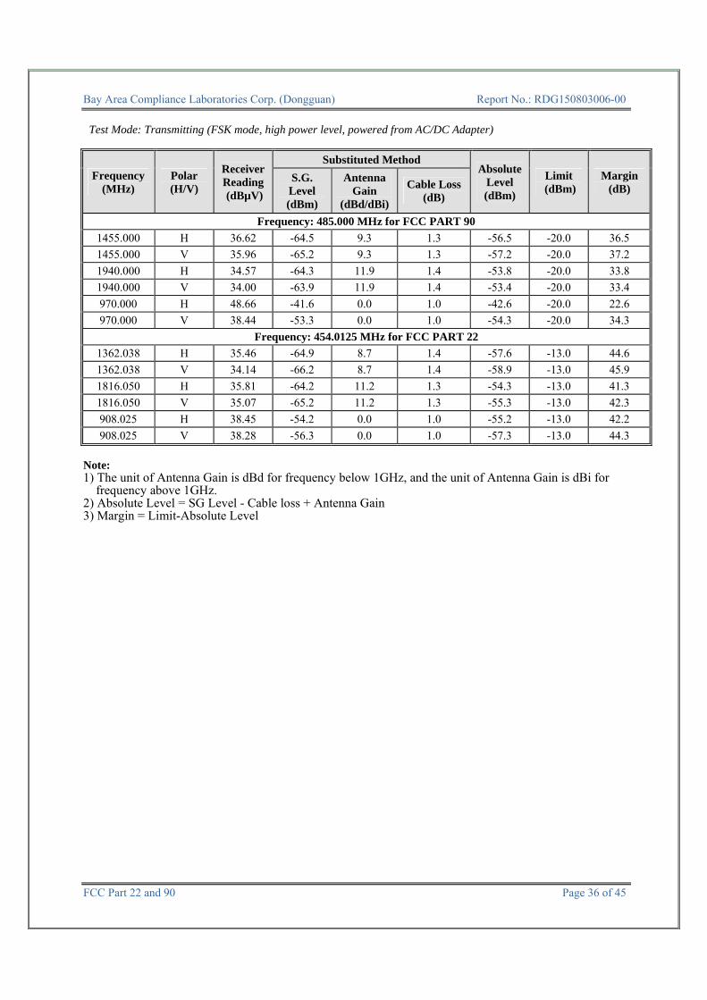
Test Mode: Transmitting (FSK mode, high power level, powered from AC/DC Adapter)
Frequency (MHz)
Polar (H/V)
Receiver Reading (dBµV)
Substituted Method Absolute
Level (dBm)
Limit (dBm)
Margin (dB)
S.G. Level (dBm)
Antenna Gain
(dBd/dBi)
Cable Loss (dB)
Frequency: 485.000 MHz for FCC PART 90 1455.000 H 36.62 -64.5 9.3 1.3 -56.5 -20.0 36.5 1455.000 V 35.96 -65.2 9.3 1.3 -57.2 -20.0 37.2 1940.000 H 34.57 -64.3 11.9 1.4 -53.8 -20.0 33.8 1940.000 V 34.00 -63.9 11.9 1.4 -53.4 -20.0 33.4 970.000 H 48.66 -41.6 0.0 1.0 -42.6 -20.0 22.6 970.000 V 38.44 -53.3 0.0 1.0 -54.3 -20.0 34.3
Frequency: 454.0125 MHz for FCC PART 22 1362.038 H 35.46 -64.9 8.7 1.4 -57.6 -13.0 44.6 1362.038 V 34.14 -66.2 8.7 1.4 -58.9 -13.0 45.9 1816.050 H 35.81 -64.2 11.2 1.3 -54.3 -13.0 41.3 1816.050 V 35.07 -65.2 11.2 1.3 -55.3 -13.0 42.3 908.025 H 38.45 -54.2 0.0 1.0 -55.2 -13.0 42.2 908.025 V 38.28 -56.3 0.0 1.0 -57.3 -13.0 44.3
Note: 1) The unit of Antenna Gain is dBd for frequency below 1GHz, and the unit of Antenna Gain is dBi for
frequency above 1GHz. 2) Absolute Level = SG Level - Cable loss + Antenna Gain 3) Margin = Limit-Absolute Level

Bay Area Compliance Laboratories Corp. (Dongguan) Report No.: RDG150803006-00
FCC Part 22 and 90 Page 37 of 45
FCC §2.1055 & § 22.355 & §90.213- FREQUENCY STABILITY Applicable Standard FCC §2.1055, § 22.355, §90.213 Test Equipment List and Details
Manufacturer Description Model No. Serial No. Calibration Date
Calibration Due Date
R&S Spectrum Analyzer FSP 38 100478 2015-05-09 2016-05-09
Dongzhixu High Temperature Test Chamber DP1000 201105083-4 2015-08-11 2016-08-11
UNI-T Multimeter UT39A M130199938 2015-04-10 2016-04-10
AA-MCS Attenuator(40dB) CAT-50-40-200-Nm-Nf 0602-010 2015-05-06 2016-05-06
E-Microwave DC Blocking EMDCB-00036 0E01201047 2015-05-06 2016-05-06Pasternack RF Coaxial Cable RF-01 / 2015-05-06 2016-05-06
* Statement of Traceability: Bay Area Compliance Laboratories Corp. (Dongguan) attests that all calibrations have
been performed, traceable to National Primary Standards and International System of Units (SI). Test Procedure Frequency Stability vs. Temperature: The equipment under test was connected to DC power supply and the RF output was connected to a frequency counter via feed-through attenuators. The EUT was placed inside the temperature chamber. The power leads and RF output cable exited the chamber through an opening made for the purpose. After the temperature stabilized for approximately 20 minutes, the frequency output was recorded from the counter. The frequency stability shall be measured with variation of primary supply voltage as follows: (1) Vary primary supply voltage from 85 to 115 percent of the nominal value. (2) For hand carried, battery powered equipment, reduce primary supply voltage to the battery operating end point
which shall be specified by the manufacturer. Test Data
Environmental Conditions
Temperature: 27.1 °C
Relative Humidity: 58 % ATM Pressure: 100kPa
The testing was performed by Allen Qiao on 2015-08-25.

Bay Area Compliance Laboratories Corp. (Dongguan) Report No.: RDG150803006-00
FCC Part 22 and 90 Page 38 of 45
Note: The EUT may be used in a base station or a mobile station configuration, the strict limits
were applied.
Test Mode: Transmitting
FCC PART 90
Reference Frequency:485.000 MHz, Limit: 1.5 ppm Temerature Voltage Reading Frequency Error
VDC MHz ppm -30 13.6 485.00021 0.43 -20 13.6 485.00045 0.93 -10 13.6 485.00028 0.58 0 13.6 485.00037 0.76
10 13.6 485.00026 0.54 20 13.6 485.00030 0.62 30 13.6 485.00045 0.93 40 13.6 485.00032 0.66 50 13.6 485.00031 0.64
25 10.8 485.00035 0.72 15.6 485.00015 0.31
Reference Frequency:485.000 MHz, Limit: 1.5 ppm
Temerature Voltage Reading Frequency Error VAC MHz ppm -30 120 485.00038 0.78 -20 120 485.00032 0.66 -10 120 485.00013 0.27 0 120 485.00022 0.45
10 120 485.00034 0.70 20 120 485.00028 0.58 30 120 485.00037 0.76 40 120 485.00026 0.54 50 120 485.00024 0.49
25 102 485.00028 0.58 138 485.00032 0.66

Bay Area Compliance Laboratories Corp. (Dongguan) Report No.: RDG150803006-00
FCC Part 22 and 90 Page 39 of 45
FCC PART 22
Reference Frequency: 454.0125MHz, Limit: 2.5 ppm Temerature Voltage Reading Frequency Error
VDC MHz ppm -30 13.6 454.01264 0.31 -20 13.6 454.01284 0.75 -10 13.6 454.01285 0.77 0 13.6 454.01275 0.55
10 13.6 454.01256 0.13 20 13.6 454.012700 0.44 30 13.6 454.01279 0.64 40 13.6 454.01266 0.35 50 13.6 454.01269 0.42
25 10.8 454.01261 0.24 15.6 454.01269 0.42
Reference Frequency: 454.0125MHz, Limit: 2.5 ppm Temerature Voltage Reading Frequency Error
VAC MHz ppm -30 120 454.01256 0.13 -20 120 454.01268 0.40 -10 120 454.01274 0.53 0 120 454.01267 0.37
10 120 454.01262 0.26 20 120 454.01282 0.70 30 120 454.01264 0.31 40 120 454.01276 0.57 50 120 454.01284 0.75
25 102 454.01244 -0.13 138 454.01263 0.29
Bay Area Compliance Laboratories Corp. (Dongguan) Report No.: RDG150803006-00
FCC Part 22 and 90 Page 40 of 45
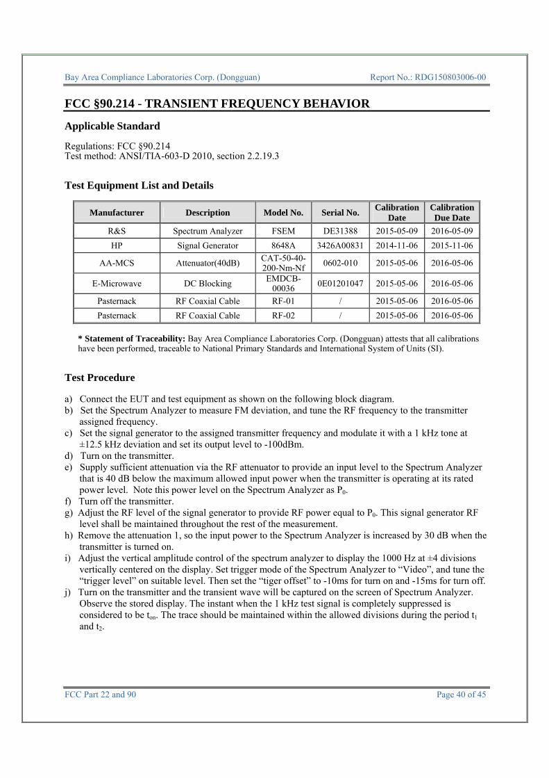
FCC §90.214 - TRANSIENT FREQUENCY BEHAVIOR Applicable Standard Regulations: FCC §90.214 Test method: ANSI/TIA-603-D 2010, section 2.2.19.3 Test Equipment List and Details
Manufacturer Description Model No. Serial No. Calibration Date
Calibration Due Date
R&S Spectrum Analyzer FSEM DE31388 2015-05-09 2016-05-09HP Signal Generator 8648A 3426A00831 2014-11-06 2015-11-06
AA-MCS Attenuator(40dB) CAT-50-40-200-Nm-Nf 0602-010 2015-05-06 2016-05-06
E-Microwave DC Blocking EMDCB-00036 0E01201047 2015-05-06 2016-05-06
Pasternack RF Coaxial Cable RF-01 / 2015-05-06 2016-05-06Pasternack RF Coaxial Cable RF-02 / 2015-05-06 2016-05-06
* Statement of Traceability: Bay Area Compliance Laboratories Corp. (Dongguan) attests that all calibrations have been performed, traceable to National Primary Standards and International System of Units (SI).
Test Procedure a) Connect the EUT and test equipment as shown on the following block diagram. b) Set the Spectrum Analyzer to measure FM deviation, and tune the RF frequency to the transmitter
assigned frequency. c) Set the signal generator to the assigned transmitter frequency and modulate it with a 1 kHz tone at
±12.5 kHz deviation and set its output level to -100dBm. d) Turn on the transmitter. e) Supply sufficient attenuation via the RF attenuator to provide an input level to the Spectrum Analyzer
that is 40 dB below the maximum allowed input power when the transmitter is operating at its rated power level. Note this power level on the Spectrum Analyzer as P0.
f) Turn off the transmitter. g) Adjust the RF level of the signal generator to provide RF power equal to P0. This signal generator RF
level shall be maintained throughout the rest of the measurement. h) Remove the attenuation 1, so the input power to the Spectrum Analyzer is increased by 30 dB when the
transmitter is turned on. i) Adjust the vertical amplitude control of the spectrum analyzer to display the 1000 Hz at ±4 divisions
vertically centered on the display. Set trigger mode of the Spectrum Analyzer to “Video”, and tune the “trigger level” on suitable level. Then set the “tiger offset” to -10ms for turn on and -15ms for turn off.
j) Turn on the transmitter and the transient wave will be captured on the screen of Spectrum Analyzer. Observe the stored display. The instant when the 1 kHz test signal is completely suppressed is considered to be ton. The trace should be maintained within the allowed divisions during the period t1 and t2.

Bay Area Compliance Laboratories Corp. (Dongguan) Report No.: RDG150803006-00
FCC Part 22 and 90 Page 41 of 45
k) Then turn off the transmitter, and another transient wave will be captured on the screen of Spectrum
Analyzer. The trace should be maintained within the allowed divisions during the period t3.
Test Data
Environmental Conditions
Temperature: 27.3 °C
Relative Humidity: 59 % ATM Pressure: 100.2 kPa
The testing was performed by Allen Qiao on 2015-08-18 and 2015-11-04.
Channel Spacing (kHz)
Transient Period (ms)
Maximum frequencydifference Result
12.5 <10(t1 ) ±12.5 kHz
Pass <25(t2 ) ±6.25 kHz <10 (t3 ) ±12.5 kHz
Please refer to the following plots.
Spectrum Analyzer
EUT
Signal Generator
Attenuator 1 Attenuator 2 Com
biner
Spectrum Analyzer

Bay Area Compliance Laboratories Corp. (Dongguan) Report No.: RDG150803006-00
FCC Part 22 and 90 Page 42 of 45
Turn on – 485 MHz, FM Mode, High power level
Turn off – 485 MHz, FM Mode, High power level

Bay Area Compliance Laboratories Corp. (Dongguan) Report No.: RDG150803006-00
FCC Part 22 and 90 Page 43 of 45
Turn on – 485 MHz, FM Mode, Low power level
Turn off – 485MHz, FM Mode, Low power level

Bay Area Compliance Laboratories Corp. (Dongguan) Report No.: RDG150803006-00
FCC Part 22 and 90 Page 44 of 45
Turn on – 485 MHz, 4FSK Mode, High power level
Turn off – 485 MHz, 4FSK Mode, High power level

Bay Area Compliance Laboratories Corp. (Dongguan) Report No.: RDG150803006-00
FCC Part 22 and 90 Page 45 of 45
***** END OF REPORT *****
Turn on – 485 MHz, 4FSK Mode, Low power level
Turn off – 485 MHz, 4FSK Mode, Low power level