FC722 Cerberus Fire control panel - zrelektronik.com€¦ · CPS Fire Safety FC722 Cerberus ... CPS...
10
Building Technologies CPS Fire Safety FC722 Cerberus ® PRO Fire control panel Series FS720 (IP4) Compact, prefabricated microprocessor-controlled fire control panel for the connection of up to 252 addresses Fire control panel can be used as stand-alone version or networked Up to 64 stations (fire control panels and fire terminals) can be connected in one network Integrated emergency operation function Redundant network node, degrade operation according to EN 54 Fast Ethernet interface for heterogeneous network Integrated user-friendly operating unit Optional printer, key switch, LED indicators Slots for RS232, RS485 serial ports Emergency power supply for up to 72 h emergency power time Detection and automatic read-in (auto configuration) of all C-NET devices, pro- viding immediate simple operation Processes signals from the Cerberus PRO FD720 detector series Floor repeater devices, alarm devices and mimic displays in the detector loop (C-NET) Flexible programming of complex applications and controls Stored data can be uploaded via remote access Firmware download of all processor controlled control panel components
Transcript of FC722 Cerberus Fire control panel - zrelektronik.com€¦ · CPS Fire Safety FC722 Cerberus ... CPS...

Building TechnologiesCPS Fire Safety
FC722 Cerberus® PRO
Fire control panel
Series FS720 (IP4)
Compact, prefabricated microprocessor-controlled fire control panel for the connection of up to 252 addresses
Fire control panel can be used as stand-alone version or networked Up to 64 stations (fire control panels and fire terminals) can be connected in
one network Integrated emergency operation function Redundant network node, degrade operation according to EN 54 Fast Ethernet interface for heterogeneous network Integrated user-friendly operating unit Optional printer, key switch, LED indicators Slots for RS232, RS485 serial ports Emergency power supply for up to 72 h emergency power time Detection and automatic read-in (auto configuration) of all C-NET devices, pro-
viding immediate simple operation Processes signals from the Cerberus PRO FD720 detector series Floor repeater devices, alarm devices and mimic displays in the detector loop
(C-NET) Flexible programming of complex applications and controls Stored data can be uploaded via remote access Firmware download of all processor controlled control panel components
2
Building Technologies CPS Fire Safety
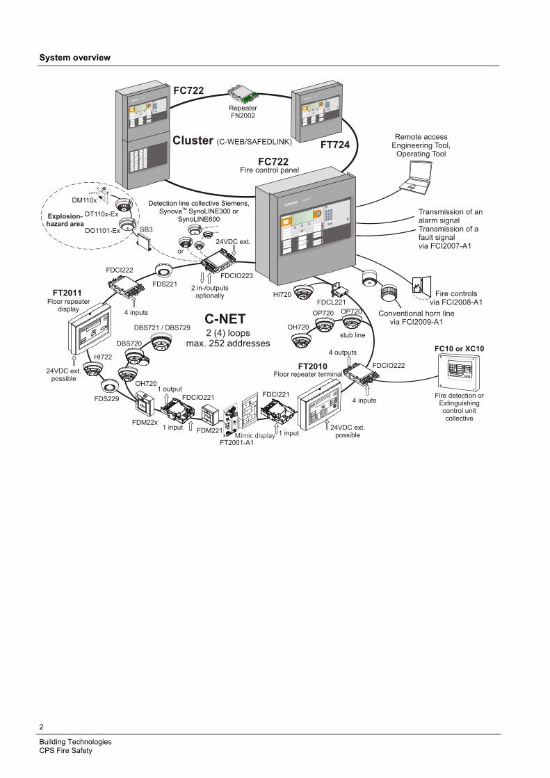
System overview
FC10 or XC10
Fire detection orExtinguishingcontrol unitcollective
2 (4) loopsmax. 252 addresses
C-NET
FT2010
stub line
FDCI222
4 inputs
4 outputs
Floor repeater terminal
24VDC ext.possible
FT2011Floor repeater
display
24VDC ext.possible
FC722Fire control panel
Fire controlsvia FCI2008-A1
Remote accessEngineering Tool,
Operating Tool
FDCL221
FDCIO222
FDM22xFDM221
FDS221
DBS720
OH720
HI722
HI720
OP7204 inputs Conventional horn linevia FCI2009-A1
FDS229 FDCIO221
1 input
1 output
1 input
FDCI221
OH720
24VDC ext.
2 in-/outputsoptionally
FDCIO223
SB3DO1101-Ex
DT110x-Ex
DM110x
avoid electrostaticcharging!
avoid electrostaticcharging!
or
Cluster (C-WEB/SAFEDLINK)
RepeaterFN2002
FT724
FC722
Explosion-hazard area
Detection line collective Siemens, Synova SynoLINE300 or
SynoLINE600
TMTransmission of analarm signalTransmission of afault signalvia FCI2007-A1
Mimic displayFT2001-A1
OP720
DBS721 / DBS729
3
Building Technologies CPS Fire Safety
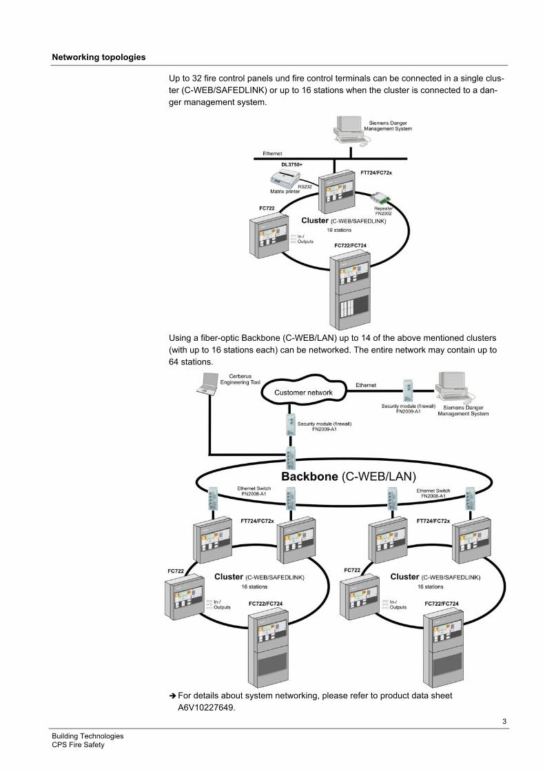
Networking topologies
Up to 32 fire control panels und fire control terminals can be connected in a single clus-ter (C-WEB/SAFEDLINK) or up to 16 stations when the cluster is connected to a dan-ger management system.
Using a fiber-optic Backbone (C-WEB/LAN) up to 14 of the above mentioned clusters (with up to 16 stations each) can be networked. The entire network may contain up to 64 stations.
For details about system networking, please refer to product data sheet
A6V10227649.
4
Building Technologies CPS Fire Safety
Characteristics
– The FC722 is a compact fire control panel with an integrated operating unit that can process signals from FD720 devices.
– The control panel can be used as a stand-alone unit or in a network. – The control panel can be programmed with the user-friendly Cerberus-Engineering-
Tool to create a system with great versatility. – All detector lines are monitored for ground faults. – Adaptation of the user text directly on the terminal or with the software engineering
tool. – Up to 2000 events can be stored according to various criteria. – Automatic summer/winter time change. – Connection of Siemens Danger Management System
Functional elements
Operating unit The following are located on the operating unit:
– CPU module and the electronics for the operating unit – Ethernet connection – Slots for RS232, RS485 modules and networking modules (SAFEDLINK) – Space for 'Kaba' or 'Nordic' key switch – Space for event printer (except FC722-YZ)
Periphery board The following are located on the periphery board:
– Connection terminals for C-NET loops, remote transmission (alarm, fault), horn output, programmable control inputs/outputs, monitored alarm and fault output, degrade supply, power supply
– Plug-in position for loop extension (C-NET)
Power supply 70 W or 150 W, emergency power supply The power supply supplies the hardware and charges the batteries
– The batteries supply the emergency power in case of power failure
Housing A pivoting mounting panel can be installed on the housing backplane to allow installa-tion of:
– 1 fire brigade periphery module (for Germany) – 1 sounder module (can also be mounted onto the U-rail TS35)
Configuration The FXS7212 Cerberus-Engineering-Tool permits the system to be adapted to specific customers' requirements.
Application ranges
The FC722 is ideally suited for applications, e.g. in workshops, hotels, etc. or when networked as part of much larger applications. The FC722 can be used by the flexible cross-linking possibilities however also for ex-tensive systems.
5
Building Technologies CPS Fire Safety
Operation
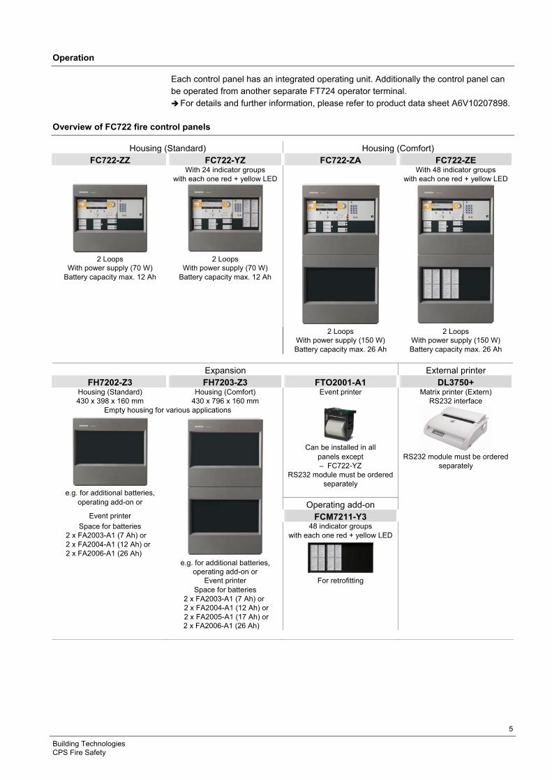
Each control panel has an integrated operating unit. Additionally the control panel can be operated from another separate FT724 operator terminal. For details and further information, please refer to product data sheet A6V10207898.
Overview of FC722 fire control panels
Housing (Standard) Housing (Comfort) FC722-ZZ FC722-YZ FC722-ZA FC722-ZE
With 24 indicator groups With 48 indicator groups with each one red + yellow LED with each one red + yellow LED
2 Loops 2 Loops
With power supply (70 W) With power supply (70 W) Battery capacity max. 12 Ah Battery capacity max. 12 Ah
2 Loops 2 Loops With power supply (150 W) With power supply (150 W) Battery capacity max. 26 Ah Battery capacity max. 26 Ah
Expansion External printer FH7202-Z3 FH7203-Z3 FTO2001-A1 DL3750+
Housing (Standard) Housing (Comfort) Event printer Matrix printer (Extern) 430 x 398 x 160 mm 430 x 796 x 160 mm RS232 interface
Empty housing for various applications
Can be installed in all
panels except RS232 module must be ordered – FC722-YZ separately
RS232 module must be ordered separately
e.g. for additional batteries, operating add-on or Operating add-on
Event printer FCM7211-Y3 Space for batteries 48 indicator groups
2 x FA2003-A1 (7 Ah) or with each one red + yellow LED 2 x FA2004-A1 (12 Ah) or 2 x FA2006-A1 (26 Ah)
e.g. for additional batteries, operating add-on or
Event printer For retrofitting Space for batteries 2 x FA2003-A1 (7 Ah) or 2 x FA2004-A1 (12 Ah) or 2 x FA2005-A1 (17 Ah) or 2 x FA2006-A1 (26 Ah)
6
Building Technologies CPS Fire Safety
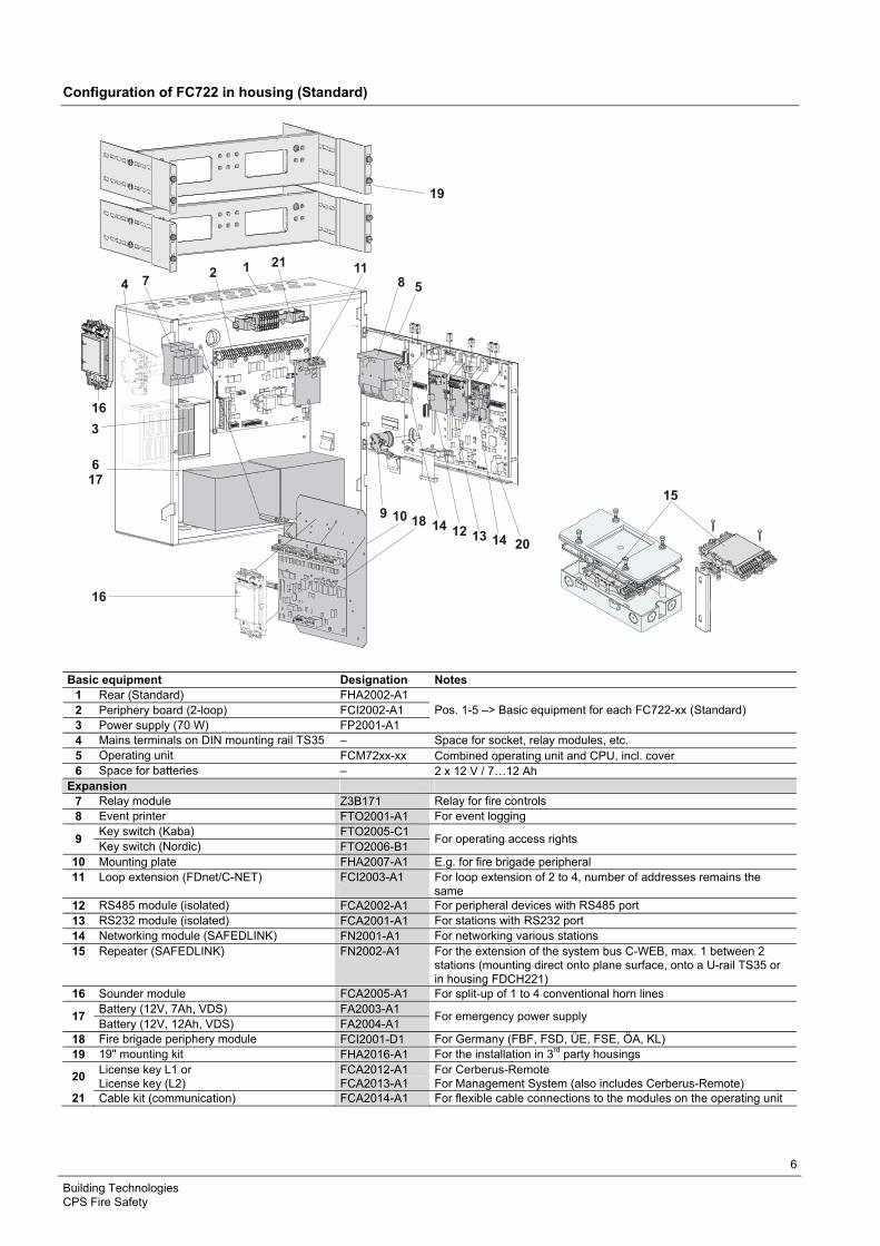
Configuration of FC722 in housing (Standard)
2 1
3
617
18
4 8
10
5
12 13 14
7
9
19
11
15
16
16
2014
21
Basic equipment Designation Notes 1 Rear (Standard) FHA2002-A1 2 Periphery board (2-loop) FCI2002-A1 3 Power supply (70 W) FP2001-A1
Pos. 1-5 –> Basic equipment for each FC722-xx (Standard)
4 Mains terminals on DIN mounting rail TS35 – Space for socket, relay modules, etc. 5 Operating unit FCM72xx-xx Combined operating unit and CPU, incl. cover 6 Space for batteries – 2 x 12 V / 7…12 Ah
Expansion 7 Relay module Z3B171 Relay for fire controls 8 Event printer FTO2001-A1 For event logging
Key switch (Kaba) FTO2005-C1 9
Key switch (Nordic) FTO2006-B1 For operating access rights
10 Mounting plate FHA2007-A1 E.g. for fire brigade peripheral 11 Loop extension (FDnet/C-NET) FCI2003-A1 For loop extension of 2 to 4, number of addresses remains the
same 12 RS485 module (isolated) FCA2002-A1 For peripheral devices with RS485 port 13 RS232 module (isolated) FCA2001-A1 For stations with RS232 port 14 Networking module (SAFEDLINK) FN2001-A1 For networking various stations 15 Repeater (SAFEDLINK) FN2002-A1 For the extension of the system bus C-WEB, max. 1 between 2
stations (mounting direct onto plane surface, onto a U-rail TS35 or in housing FDCH221)
16 Sounder module FCA2005-A1 For split-up of 1 to 4 conventional horn lines Battery (12V, 7Ah, VDS) FA2003-A1
17 Battery (12V, 12Ah, VDS) FA2004-A1
For emergency power supply
18 Fire brigade periphery module FCI2001-D1 For Germany (FBF, FSD, ÜE, FSE, ÖA, KL) 19 19" mounting kit FHA2016-A1 For the installation in 3rd party housings
20 License key L1 or License key (L2)
FCA2012-A1 FCA2013-A1
For Cerberus-Remote For Management System (also includes Cerberus-Remote)
21 Cable kit (communication) FCA2014-A1 For flexible cable connections to the modules on the operating unit

7
Building Technologies CPS Fire Safety
Configuration of FC722 in housing (Comfort)
14
1
2
3
4
5
617
7
8
912 13 14
18
19
8
1018
22
16
15
11
16
20
21
21
Basic equipment Designation Notes 1 Rear (Comfort) FHA2003-A1 2 Periphery board (2-loop) FCI2002-A1 3 Power supply (SV 24V-150 W) V24230-Z6-A4
Pos. 1-5 –> Basic equipment for each FC722-xx (Comfort)
4 Mains terminals on DIN mounting rail TS35 – Space for socket, relay modules, etc. 5 Operating unit FCM72xx-xx Combined operating unit and CPU, incl. cover 6 Space for batteries – 2 x 12 V / 7… 26 Ah
Expansion 7 Relay module Z3B171 Relay for fire controls 8 Event printer FTO2001-A1 For event logging
Key switch (Kaba) FTO2005-C1 9
Key switch (Nordic) FTO2006-B1 For operating access rights
10 Mounting plate FHA2007-A1 E.g. for fire brigade peripheral 11 Loop extension (FDnet/C-NET) FCI2003-A1 For loop extension of 2 to 4, number of addresses remains the
same 12 RS485 module (isolated) FCA2002-A1 For peripheral devices with RS485 port 13 RS232 module (isolated) FCA2001-A1 For stations with RS232 port 14 Networking module (SAFEDLINK) FN2001-A1 For networking various stations 15 Repeater (SAFEDLINK) FN2002-A1 For the extension of the system bus C-WEB, max. 1 between 2
stations (mounting direct onto plane surface, onto a U-rail TS35 or in housings FDCH221)
16 Sounder module FCA2005-A1 For split-up of 1 to 4 conventional horn lines
8
Building Technologies CPS Fire Safety
Battery (12 V, 7 Ah, VDS) FA2003-A1 Battery (12 V, 12 Ah, VDS) FA2004-A1 17 Battery (12 V, 26 Ah, VDS) FA2006-A1
For emergency power supply
18 Fire brigade periphery module FCI2001-D1 For Germany (FBF, FSD, ÜE, FSE, ÖA, KL) 19 19" mounting kit FHA2016-A1 For the installation in 3rd party housings
20 License key L1 or License key (L2)
FCA2012-A1 FCA2013-A1
For Cerberus-Remote For Management System (also includes Cerberus-Remote)
21 Cable kit (communication) FCA2014-A1 For flexible cable connections to the modules on the operating unit22 Power supply kit (150 W, B) FP2005-A1 For additional power supply
Technical data
FC722 in housing (Standard) FC722 in housing (Comfort)
Mains voltage AC 85… 265 V AC 98 …127 V / AC 196…253 V
Power supply 70 W 150 W
Operating voltage DC 21… 28.6 V DC 21… 28.4 V
Operating current max. 2.5 A max. 5 A
Battery capacity 2 x 12 V, 7… 12 Ah 2 x 12 V, 26 Ah
Battery monitoring yes yes
Mains monitoring yes yes
Connectable detector series Cerberus PRO FD720 (C-NET) Cerberus PRO FD720 (C-NET)
Number of lines – Loops (with loop extension) or – Stub lines
2 (4) 4 (8)
2 (4) 4 (8)
Number of addresses max. 252 max. 252
Integrated inputs/outputs – Relay output
– Remote transmission alarm – Remote transmission fault
– Monitored outputs – Alarm – Fault – Horn
– Free programmable inputs/outputs
1 1
1 1 1 8
1 1
1 1 1 8
Operating unit integrated integrated
Plug-in position for serial interfaces RS232, RS485
2 2
Plug-in position for network module 2 2
Plug-in position for loop extension 1 1
Mounting place for cable kit (communication) 1 2
Sounder module max. 1 max. 1
Ethernet connection RJ45 1 1
Operating temperature -8… +42 °C -8… +42 °C
Storage temperature -20… +60 °C -20… +60 °C
Humidity (no condensation permitted) ≤95 % rel. ≤95 % rel.
Dimensions (B x H x T) – Without cover cap – With cover cap
430 x 398 x 160 mm 430 x 398 x 188 mm
430 x 796 x 160 mm 430 x 796 x 188 mm
Color – Housing – Cover
grey, ~RAL 7035
grey, ~RAL-Design 050 00 00
grey, ~RAL 7035
grey, ~RAL-Design 050 00 00
Protection category (IEC 60529) IP30 IP30
Approvals – VdS – LPCB
G209076 126aw/06
G209076 126aw/06

9
Building Technologies CPS Fire Safety
FC722
Details for ordering
Type Part no Designation Weight
Fire control panels FC722-ZZ S54400-C29-A5 Fire control panel (2L) 10.660 kg
FC722-YZ S54400-C29-A4 Fire control panel (2L, 1LED) 10.500 kg
FC722-ZA S54400-C29-A2 Fire control panel (2L) 18.250 kg
FC722-ZE S54400-C29-A1 Fire control panel (2L, 2LED) 20.850 kg
Expansion Z3B171 BPZ:4843830001 Relay module 250 VAC / 10 A (1 relay) 0.042 kg
FTO2001-A1 A5Q00010126 Event printer 0.250 kg
– A5Q00017619 Replacement printer rolls (10 rolls) 0.090 kg
FTO2005-C1 A5Q00010113 Key switch (Kaba) 0.013 kg
FTO2006-B1 A5Q00010129 Key switch (Nordic) 0.050 kg
FHA2007-A1 A5Q00010151 Mounting plate 0.800 kg
FCI2003-A1 A5Q00010136 Loop extension (FDnet/C-NET) 0.064 kg
FCA2002-A1 A5Q00009923 RS485 module (isolated) 0.067 kg
FCA2001-A1 A5Q00005327 RS232 module (isolated) 0.068 kg
FN2001-A1 A5Q00012851 Network module (SAFEDLINK) 0.077 kg
FN2002-A1 S24236-B2502-A1 Repeater (SAFEDLINK) 0.154 kg
FCA2005-A1 A5Q00014866 Sounder module 0.140 kg
FCA2014-A1 A5Q00023027 Cable kit (communication) 0.224 kg
FCI2001-D1 A5Q00013100 Fire brigade periphery module 0.482 kg
FH7202-Z3 S54400-B70-A101 Housing (Standard) 7.500 kg
FH7203-Z3 S54400-B71-A101 Housing (Comfort) 15.000 kg
FCM7211-Y3 S54400-F75-A1 Operating add-on (2xLED-ind.) 2.600 kg
FHA2016-A1 A5Q00020179 19" mounting kit 3.000 kg
FN2006-A1 S54400-A109-A1 Fiber network module (SM) 0.770 kg
FN2007-A1 S54400-A110-A1 Fiber network module (MM) 0.770 kg
FP2003-A1 A5Q00016005 Power supply kit (70 W) 0.650 kg
FP2004-A1 A5Q00020825 Power supply kit (150 W) for installation in
empty housing
1.366 kg
Additional power supply
FP2005-A1 A5Q00018779 Power supply kit (150 W, B) ) for cascad-
ing
1.100 kg
Networks (backbone) FN2008-A1 S54400-F94-A1 Ethernet switch 0.800 kg
FN2009-A1 S54400-F95-A1 Security module 0.800 kg
FHA2029-A1 S54400-B79-A1 Mounting kit for Ethernet switch (Comfort) 0.500 kg
FHA2030-A1 S54400-B81-A1 Mounting kit for Ethernet switch
(Large Ext.)
0.500 kg
Batteries FA2003-A1 A5Q00019353 Battery (12 V, 7 Ah, VDS) 2.450 kg
FA2004-A1 A5Q00019354 Battery (12 V, 12 Ah, VDS) 3.930 kg
FA2005-A1 A5Q00019677 Battery (12 V, 17 Ah, VDS) 5.640 kg
FA2006-A1 A5Q00019356 Battery (12 V, 26 Ah, VDS) 7.572 kg
Software license FCA2012-A1 A5Q00018856 License key (L1) 0.010 kg
FCA2013-A1 A5Q00018857 License key (L2) 0.010 kg
External printer DL3750+ A5Q00023962 Matrix printer (Extern) 7.300 kg
Spare part – A5Q00023963 Black typewriter ribbon for matrix printer
DL3750+
0.078 kg

Siemens Switzerland Ltd Infrastructure & Cities Sector Building Technologies Division International Headquarters CPS Fire Safety Gubelstrasse 22 CH-6301 Zug Tel. +41 41 724 24 24 www.siemens.com/buildingtechnologies
© 2012 Copyright bySiemens Switzerland Ltd
Data and design subject to change without notice.Supply subject to availability.
Document no. A6V10206525_e_en_-- Manual FS720
Edition 04.2012 Section 1