FBIP-21 BACnet/IPt adapter module user’s manual · PDF fileBACnet is a standard data...
68
Options for ABB drives, converters and inverters User’s manual FBIP-21 BACnet/IP adapter module
Transcript of FBIP-21 BACnet/IPt adapter module user’s manual · PDF fileBACnet is a standard data...

Options for ABB drives, converters and inverters
User’s manualFBIP-21 BACnet/IP adapter module

List of related manuals
You can find manuals and other product documents in PDF format on the Internet. See section Document library on the Internet on the inside of the back cover. For manuals not available in the Document library, contact your local ABB representative.
ACH580-01 manuals
Drive manuals and guides Code (EN/Multilingual)
ACH580 HVAC control program firmware manual
3AXD50000027537

6. Start-up
3AFE68462401 Rev D
fety
2007 ABB Oy. All Rights Reserved.
User’s manual
FBIP-21 BACnet/IP adapter module
3AXD50000028468 Rev AENEFFECTIVE: 2016-01-27
2016 ABB OyAll Rights Reserved.
1. Safety instructions
Table of contents
4. Mechanical installation
5. Electrical installation


Table of contents 5
Table of contents
List of related manuals . . . . . . . . . . . . . . . . . . . . . . . . . . . . . . . . . 2
1. Safety instructions
Contents of this chapter . . . . . . . . . . . . . . . . . . . . . . . . . . . . . . . . 9Use of warnings . . . . . . . . . . . . . . . . . . . . . . . . . . . . . . . . . . . . . . 9Safety in installation . . . . . . . . . . . . . . . . . . . . . . . . . . . . . . . . . . 10
2. Introduction to the manual
Contents of this chapter . . . . . . . . . . . . . . . . . . . . . . . . . . . . . . . 11Purpose of the manual . . . . . . . . . . . . . . . . . . . . . . . . . . . . . . . . 11Applicability . . . . . . . . . . . . . . . . . . . . . . . . . . . . . . . . . . . . . . . . 11Compatibility . . . . . . . . . . . . . . . . . . . . . . . . . . . . . . . . . . . . . . . 11Cyber Security Disclaimer . . . . . . . . . . . . . . . . . . . . . . . . . . . . . 12Target audience . . . . . . . . . . . . . . . . . . . . . . . . . . . . . . . . . . . . . 12Before you start . . . . . . . . . . . . . . . . . . . . . . . . . . . . . . . . . . . . . 12Contents . . . . . . . . . . . . . . . . . . . . . . . . . . . . . . . . . . . . . . . . . . . 13Terms and abbreviations . . . . . . . . . . . . . . . . . . . . . . . . . . . . . . 14
3. Overview of the BACnet/IP network and the FBIP-21 moduleContents of this chapter . . . . . . . . . . . . . . . . . . . . . . . . . . . . . . . 17BACnet . . . . . . . . . . . . . . . . . . . . . . . . . . . . . . . . . . . . . . . . . . . . 17
BACnet supported network type with FBIP-21 . . . . . . . . . . 17Topology of the BACnet/IP network . . . . . . . . . . . . . . . . . . 18
Example 1 . . . . . . . . . . . . . . . . . . . . . . . . . . . . . . . . . . . 18Example 2 . . . . . . . . . . . . . . . . . . . . . . . . . . . . . . . . . . . 18
FBIP-21 BACnet/IP adapter module . . . . . . . . . . . . . . . . . . . . . 19Layout of the FBIP-21 BACnet/IP adapter module . . . . . . . 20
4. Mechanical installation
Contents of this chapter . . . . . . . . . . . . . . . . . . . . . . . . . . . . . . . 21Necessary tools and instructions . . . . . . . . . . . . . . . . . . . . . . . . 21Unpacking and examining the delivery . . . . . . . . . . . . . . . . . . . 21

6 Table of contents
Installing the adapter module . . . . . . . . . . . . . . . . . . . . . . . . . . . 22
5. Electrical installationContents of this chapter . . . . . . . . . . . . . . . . . . . . . . . . . . . . . . . 25Necessary tools and instructions . . . . . . . . . . . . . . . . . . . . . . . . 25General cabling instructions . . . . . . . . . . . . . . . . . . . . . . . . . . . . 25Connecting the adapter module to the BACnet/IP network . . . . 26
Connection procedure . . . . . . . . . . . . . . . . . . . . . . . . . . . . . 26
6. Start-upContents of this chapter . . . . . . . . . . . . . . . . . . . . . . . . . . . . . . . 27Configuring the BACnet/IP connection . . . . . . . . . . . . . . . . . . . . 28
FBIP-21 configuration parameters – group A (group 1) . . . . 29Activating drive control functions with ACH580 . . . . . . . . . . . . . 36
Drive control . . . . . . . . . . . . . . . . . . . . . . . . . . . . . . . . . . . . . 36Start/stop direction control . . . . . . . . . . . . . . . . . . . . . . . . . . 36Input reference select . . . . . . . . . . . . . . . . . . . . . . . . . . . . . 37
Frequency reference . . . . . . . . . . . . . . . . . . . . . . . . . . . 37Speed reference. . . . . . . . . . . . . . . . . . . . . . . . . . . . . . . 38
Miscellaneous drive control . . . . . . . . . . . . . . . . . . . . . . . . . 38Relay output control . . . . . . . . . . . . . . . . . . . . . . . . . . . . . . . 39
Data point connections . . . . . . . . . . . . . . . . . . . . . . . . . . 40Analog output control . . . . . . . . . . . . . . . . . . . . . . . . . . . . . . 40
Data point connections . . . . . . . . . . . . . . . . . . . . . . . . . . 41PID control . . . . . . . . . . . . . . . . . . . . . . . . . . . . . . . . . . . . . . 41
Data point connections . . . . . . . . . . . . . . . . . . . . . . . . . . 41Communication fault . . . . . . . . . . . . . . . . . . . . . . . . . . . . . . 42Drive feedback . . . . . . . . . . . . . . . . . . . . . . . . . . . . . . . . . . . 43Fault queue for drive diagnostics . . . . . . . . . . . . . . . . . . . . . 45
Starting up fieldbus communication for ACH580 drives . . . . . . . 46Parameter setting examples . . . . . . . . . . . . . . . . . . . . . . . . 47
Frequency control. . . . . . . . . . . . . . . . . . . . . . . . . . . . . . 47
7. Communication protocolContents of this chapter . . . . . . . . . . . . . . . . . . . . . . . . . . . . . . . 49BACnet/IP . . . . . . . . . . . . . . . . . . . . . . . . . . . . . . . . . . . . . . . . . 49Prioritizing commands . . . . . . . . . . . . . . . . . . . . . . . . . . . . . . . . 49
Table of contents 7
BACnet interoperability building blocks . . . . . . . . . . . . . . . . . . . 50BACnet object list . . . . . . . . . . . . . . . . . . . . . . . . . . . . . . . . . . . . 51
AI object . . . . . . . . . . . . . . . . . . . . . . . . . . . . . . . . . . . . . . . 51AO object . . . . . . . . . . . . . . . . . . . . . . . . . . . . . . . . . . . . . . 51AV object . . . . . . . . . . . . . . . . . . . . . . . . . . . . . . . . . . . . . . 52BI object . . . . . . . . . . . . . . . . . . . . . . . . . . . . . . . . . . . . . . . . 56BO object . . . . . . . . . . . . . . . . . . . . . . . . . . . . . . . . . . . . . . . 57BV object . . . . . . . . . . . . . . . . . . . . . . . . . . . . . . . . . . . . . . . 57
8. Diagnostics
Contents of this chapter . . . . . . . . . . . . . . . . . . . . . . . . . . . . . . . 61Fault and warning messages . . . . . . . . . . . . . . . . . . . . . . . . . . . 61LEDs . . . . . . . . . . . . . . . . . . . . . . . . . . . . . . . . . . . . . . . . . . . . . 62
9. Technical data
Contents of this chapter . . . . . . . . . . . . . . . . . . . . . . . . . . . . . . . 65Layout diagram . . . . . . . . . . . . . . . . . . . . . . . . . . . . . . . . . . . . . 65General conditions . . . . . . . . . . . . . . . . . . . . . . . . . . . . . . . . . . . 66BACnet link . . . . . . . . . . . . . . . . . . . . . . . . . . . . . . . . . . . . . . . . 66
Further informationProduct and service inquiries . . . . . . . . . . . . . . . . . . . . . . . . . . . 67Product training . . . . . . . . . . . . . . . . . . . . . . . . . . . . . . . . . . . . . 67Providing feedback on ABB Drives manuals . . . . . . . . . . . . . . . 67Document library on the Internet . . . . . . . . . . . . . . . . . . . . . . . . 67

8 Table of contents

Safety instructions 9
1Safety instructions
Contents of this chapter
The chapter contains the warning symbols used in this manual and the safety instructions which you must obey when you install or connect an optional module to a drive, converter or inverter. If you ignore the safety instructions, injury, death or damage can occur. Read this chapter before you start the installation.
Use of warnings
Warnings tell you about conditions which can cause injury or death, or damage to the equipment. They also tell you how to prevent the danger. The manual uses these warning symbols:
Electricity warning tells you about hazards from electricity which can cause injury or death, or damage to the equipment.
General warning tells you about conditions, other than those caused by electricity, which can cause injury or death, or damage to the equipment.

10 Safety instructions
Safety in installation
These instructions are for all who install or connect an optional module to a drive, converter or inverter and need to open its front cover or door to do the work.
WARNING! Obey these instructions. If you ignore them, injury or death, or damage to the equipment can occur.
• If you are not a qualified electrician, do not do installation or maintenance work.
• Disconnect the drive, converter or inverter from all possible power sources. After you have disconnected the drive, converter or inverter, always wait for 5 minutes to let the intermediate circuit capacitors discharge before you continue.
• Disconnect all dangerous voltages connected to other control signal connectors in reach. For example, it is possible that 230 V AC is connected from outside to a relay output of the drive, converter or inverter.
• Always use a multimeter to make sure that there are no parts under voltage in reach. The impedance of the multimeter must be at least 1 Mohm.

Introduction to the manual 11
2Introduction to the manual
Contents of this chapter
This chapter contains general information on the manual and gives the compatibility information of the FBIP-21 adapter module.
Purpose of the manual
The manual provides information on installing, commissioning and using the FBIP-21 BACnet adapter module.
Applicability
This manual applies to the FBIP-21 BACnet/IP adapter module, SW version 0.41 and later.
Compatibility
The FBIP-21 adapter module is compatible with the following drives and protocols:
Drives ACH580
Protocols • Ethernet standards IEEE 802.3 and IEEE 802.3u• All BACnet/IP clients that support protocol version 1,
revision 12.

12 Introduction to the manual
Cyber Security Disclaimer
This product is designed to be connected to and to communicate information and data via a network interface. It is Customer's sole responsibility to provide and continuously ensure a secure connection between the product and Customer network or any other network (as the case may be). Customer shall establish and maintain any appropriate measures (such as but not limited to the installation of firewalls, application of authentication measures, encryption of data, installation of anti-virus programs, etc.) to protect the product, the network, its system and the interface against any kind of security breaches, unauthorized access, interference, intrusion, leakage and/or theft of data or information. ABB and its affiliates are not liable for damages and/or losses related to such security breaches, any unauthorized access, interference, intrusion, leakage and/or theft of data or information.
Target audience
This manual is intended for people who plan the installation, install, start up, use and service the adapter module.
The manual is written for readers worldwide. Both SI and imperial units are shown.
Before you start
Before you do work on the module, read this manual and the applicable drive/converter /inverter manual that contains the hardware and safety instructions for the product in question.
You are expected to know the fundamentals of electricity, wiring, electrical components and electrical schematic symbols.

Introduction to the manual 13
Contents
The manual consists of the following chapters:• Safety instructions gives the safety instructions which you
must obey when you install a fieldbus adapter module.
• Overview of the BACnet/IP network and the FBIP-21 module contains a short description of the BACnet/IP network and the adapter module.
• Mechanical installation contains a delivery checklist and instructions on installing the adapter module.
• Electrical installation contains instructions on cabling and connecting the adapter module to the BACnet/IP network.
• Start-up presents the steps to take during the start-up of the drive with the adapter module and gives information on configuring the BACnet/IP network.
• Communication protocol describes the BACnet/IP communication protocol for the adapter module.
• Diagnostics explains how to trace faults with the status LEDs on the adapter module.
• Technical data contains the technical data of the adapter module and the Ethernet link.

14 Introduction to the manual
Terms and abbreviations
Term/Abbreviation
Explanation
AI Analog input
AO Analog output
AV Analog value
BBMD BACnet Broadcast Management Device
BI Binary input
BO Binary output
BV Binary value
C Commandable property
DHCP Dynamic Host Control Protocol. A protocol for automating the configuration of IP devices. DHCP can be used to automatically assign IP addresses and related network information.
DIO Digital inputs/outputs of the drive
EMC Electromagnetic compatibility
FBA Fieldbus adapter
FBIP-21 BACnet adapter module
One of the optional fieldbus adapter modules available for ABB drives. FBIP-21 is a device through which an ABB drive is connected to a BACnet/IP network.
Fieldbus adapter module
Device through which the drive is connected to an external communication network, that is, a fieldbus. The communication with the module is activated with a drive parameter.
FTP Foiled twisted pair
HVAC Heating, ventilating, and air conditioning
LAN Local area network
MAC ID Every node on an Ethernet network has to have a unique identifier. This node number is called MAC ID (Media Access Control ID).
R Readable property
RC Resistor -capacitor

Introduction to the manual 15
RO Relay output
STP Shielded twisted pair
UTP Unshielded twisted pair
VLAN Virtual LAN
W Writable property
WAN Wide area network
Term/Abbreviation
Explanation

16 Introduction to the manual

Overview of the BACnet/IP network and the FBIP-21 module 17
3Overview of the BACnet/IP network and the FBIP-21 module
Contents of this chapter
This chapter contains a short description of the BACnet/IP network and the FBIP-21 adapter module.
BACnet
BACnet is a standard data communication protocol that enables interoperability between different building systems (e.g. fire, security, lighting, HVAC, elevator, etc.) and devices in building automation and control applications. It enables data sharing among different types of devices from a broad set of suppliers.
BACnet supported network type with FBIP-21
The ACH580 drive can be used with the following BACnet/IP network types for transporting BACnet messages. A BACnet router is used to connect the various network types.
BACnet/IP - This type is used with the existing Ethernet infrastructure, VLAN and WAN networks. It uses the UDP/IP for compatibility with existing IP infrastructure. When it is used with multiple IP subnets, an additional device BACnet Broadcast

18 Overview of the BACnet/IP network and the FBIP-21 module
Management Devices (BBMDs) is required to manage inter-subnet BACnet broadcast messages. Each subnet requires one BBMD.
Topology of the BACnet/IP network
The below examples show the allowable topologies for a BACnet/IP network with FBIP-21 module.
Example 1
Example 2
Switch or router
Other deviceOther device ABB drive
ABB drive
BACnet building controller
ABB drive ABB drive Other devices

Overview of the BACnet/IP network and the FBIP-21 module 19
FBIP-21 BACnet/IP adapter module
The FBIP-21 BACnet/IP adapter module is an optional device for ABB drives which enables the connection of the drive to a BACnet/IP network. For example, the FBIP-21 BACnet/IP adapter module connects the ACH580 drive designed for HVAC and refrigeration applications.
Through the adapter module you can:• give control commands to the drive (for example, Start, Stop,
Run permissive)
• give a motor speed or torque reference to the drive
• give a process actual value or a process setpoint to the PID controller of the drive
• read status information and actual values from the drive
• reset a drive fault
• read and command analog and digital I/Os of the drive.
The adapter module is installed into an option slot on the drive control unit. See the drive manuals for module placement options.
20 Overview of the BACnet/IP network and the FBIP-21 module
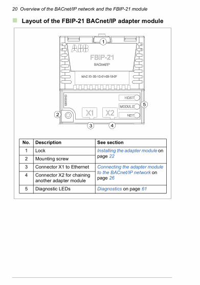
Layout of the FBIP-21 BACnet/IP adapter module
1
No. Description See section
1 Lock Installing the adapter module on page 222 Mounting screw
3 Connector X1 to Ethernet Connecting the adapter module to the BACnet/IP network on page 26
4 Connector X2 for chaining another adapter module
5 Diagnostic LEDs Diagnostics on page 61
5
2
3 4

Mechanical installation 21
4Mechanical installation
Contents of this chapter
This chapter contains a delivery checklist and instructions to install the adapter module.
Necessary tools and instructions
See the applicable drive hardware manual.
Unpacking and examining the delivery
1. Open the option package.
2. Make sure that the package contains:
• BACnet adapter module, type FBIP-21 and
• this manual.
3. Make sure that there are no signs of damage.

22 Mechanical installation
Installing the adapter module
WARNING! Obey the safety instructions. See chapter Safety instructions on page 9. If you ignore the safety instructions, injury or death can occur.
The adapter module has a specific position in the drive. Plastic pins, a lock and one screw to hold the adapter module in place. The screw also makes an electrical connection between the module and drive frame for cable shield termination.
When the adapter module is installed, it makes the signal and power connection to the drive through a 20-pin connector.
When you install or remove the adapter module from the control unit:
1. Pull out the lock.
1

Mechanical installation 23
2. Put the adapter module carefully into its position on the drive.
3. Push in the lock.
4. Tighten the screw to torque 0.8 N·m.
Note: A too high torque can break the screws. It is necessary to tighten the screw properly to fulfill the EMC requirements and to make sure the proper operation of the module.
See the applicable drive manual for further instructions on how to install the adapter module to the drive.
3
4

24 Mechanical installation

Electrical installation 25
5Electrical installation
Contents of this chapter
This chapter contains: • general cabling instructions
• instructions on connecting the adapter module to the BACnet/IP network.
Necessary tools and instructions
See the applicable drive hardware manual.
General cabling instructions
WARNING! Obey the safety instructions. See chapter Safety instructions on page 9. If you ignore the safety instructions, injury or death can occur. If you are not a qualified electrician, do not do electrical work.
• Arrange the bus cables as far away from the motor cables as possible.
• Avoid parallel runs.
• Use bushings at cable entries.

26 Electrical installation
Connecting the adapter module to the BACnet/IP network
The network cable can be CAT5 or higher, and type unshielded twisted pair (UTP), foiled twisted pair (FTP) or shielded twisted pair (STP).
When FTP or STP is used, the cable shield is connected to the drive frame through a resistor-capacitor (RC) circuit.
Connection procedure
1. Connect the network cable to the RJ-45 connector (X1) on the adapter module.
2. If you want to create a daisy chain with FBIP-21 adapter modules, connect the X2 connector of the first adapter module to X1 on the next adapter module, and so on. See BACnet/IP network topology Example 2 on page 18.

Start-up 27
6Start-up
Contents of this chapter
This chapter contains:
• information on configuring the drive for operation with the adapter module
• drive-specific instructions on starting up the drive with the adapter module
• information on configuring the client for communication with the adapter module.

28 Start-up
Configuring the BACnet/IP connection
WARNING! Obey the safety instructions given in this manual and the drive documentation.
After the adapter module has been mechanically and electrically installed according to the instructions in chapters Mechanical installation and Electrical installation, you must prepare the drive for communication with the module.
The detailed procedure for activating the module for BACnet/IP communication with the drive depends on the drive type. Normally, you must adjust a parameter to activate the communication. See the drive-specific start-up sections starting on page 36.
Once communication between the drive and the adapter module has been established, several configuration parameters are copied to the adapter module. These parameters are shown in the tables below and must be checked first and adjusted where necessary. You can adjust the parameters via a drive control panel or a PC tool.
Note: The new parameter settings take effect only when you power up the module the next time or when you activate the fieldbus adapter refresh parameter.

Start-up 29
FBIP-21 configuration parameters – group A (group 1)
Group A (group 1) corresponds to parameter group 51 in ACH580 drive.
No. Name/Value Description Default
01 FBA type Shows the fieldbus adapter type as detected by the drive. You cannot adjust this value. This parameter is read-only.
47808 = BACnet
0 = None Communication between the drive and the module is not established.
47808 = BACnet
BACnet
02 Reserved This parameter is not used by the adapter module.
-
03 Commrate Sets the bit rate of the communication and determines if the communication can be simultaneously two-way (full duplex) or only one way (half duplex).
0 = Auto
0 = Auto Auto-negotiate
1 = 100 Mbps FD
100 Mbps, full duplex
2 = 100 Mbps HD
100 Mbps, half duplex
3 = 10 Mbps FD 10 Mbps, full duplex
4 = 10 Mbps HD 10 Mbps, half duplex
04 IP configuration Sets the method for configuring the IP address, subnet mask and gateway address for the Ethernet interface.
1 = Dyn IP DHCP
0 = Static IP Configuration will be obtained from parameters 05…13.
1 = Dyn IP DHCP
Configuration is obtained via DHCP.

30 Start-up
05 IP address 1 An IP address is assigned to each IP node on a network. An IP address is a 32-bit number that is typically represented in “dotted decimal” notation consisting of four decimal integers, in the range 0…255, separated by periods. Each integer represents the value of one octet (8-bits) in the IP address. Parameters 05…08 define the four octets of the IP address.
0
0…255 IP address
… … … …
08 IP address 4 See parameter 05 IP address 1. 0
0…255 IP address
No. Name/Value Description Default

Start-up 31
09 Subnet CIDR Defines subnet masks for CIDR notation.Subnet masks are used for splitting networks into smaller networks called subnets. A subnet mask is a 32-bit binary number that splits the IP address into a network address and host address. Subnet masks are typically represented in either dotted decimal notation or the more compact CIDR notation, as shown in the table below.
0
1…31 Subnet mask in CIDR notation
No. Name/Value Description Default
Dotted decimal CIDR Dotted decimal CIDR
255.255.255.254 31 255.254.0.0 15
255.255.255.252 30 255.252.0.0 14
255.255.255.248 29 255.248.0.0 13
255.255.255.240 28 255.240.0.0 12
255.255.255.224 27 255.224.0.0 11
255.255.255.192 26 255.224.0.0 10
255.255.255.128 25 255.128.0.0 9
255.255.255.0 24 255.0.0.0 8
255.255.254.0 23 254.0.0.0 7
255.255.252.0 22 252.0.0.0 6
255.255.248.0 21 248.0.0.0 5
255.255.240.0 20 240.0.0.0 4
255.255.224.0 19 224.0.0.0 3
255.255.192.0 18 192.0.0.0 2
255.255.128.0 17 128.0.0.0 1
255.255.0.0 16

32 Start-up
10 GW address 1 Defines the four octets of the gateway address.IP gateways connect individual physical IP subnets into a unified IP network. An IP node on one subnet communicates with an IP node on another subnet by sending data to the IP gateway for forwarding. Parameters 10...13 define the four octets of the gateway address.
0
0…255 GW address
… … … …
13 GW address 4 See parameter 10 GW address 1. 0
0…255 GW address
14 Device obj ID lo Defines the device object ID for BACnet devices.The Device Object ID needs to be unique across all BACnet devices in the building network.Valid values are 0...4194303.For values 0...9999, this parameter sets the values directly. For values greater than 9999, the ID is calculated with this formula:Device ID = (10000 * par. 15) + par. 14.
0
0…9999 Device ID
15 Device obj ID hi Defines the device object ID for BACnet devices.
0
0…419 Device ID
16 Max APDU retries
Defines the number of retries to send when no response is seen to confirmed requests.
3
0…10 Number of retries.
17 APDU timeout Defines the time a client waits for response from a BACnet device.
6 s
6…60 s Waiting time.
No. Name/Value Description Default

Start-up 33
20 Timeout time Sets the delay time for directing messages to the drive before a communication loss condition is declared. • If value is zero, the feature is disabled.• If value is non zero, the timeout is in units
of 100ms. For example, a value of 300 is 30.0 seconds.
300 (30.0 s
0…65535 Delay time
21 Timeout mode Defines the message type that resets the timeout counter for detecting communication loss between the drive and the master.
1 = Any packet
1 = Any packet Any message directed to the drive resets the timeout.
2 = Control RW A write to control or reference resets the timeout.
22...26
Reserved
27 FBA Par refresh Validates any changed adapter module configuration parameter settings. After refreshing, the value reverts automatically to Done.Note: This parameter cannot be changed while the drive is running.
0 = Done
0 = Done Refreshing done
1 = Configure Refreshing
28 FBA Par table ver
Displays the parameter table revision of the fieldbus adapter module mapping file stored in the memory of the drive.In format xyz, where x = major revision numbery = minor revision numberz = correction numberThis parameter is read-only.
0 hex
No. Name/Value Description Default

34 Start-up
0..0xFFFF Parameter table revision
29 FBA Drive type code
Displays the drive type code of the fieldbus adapter module mapping file stored in the memory of the drive.This parameter is read-only.
0
0...65535 Drive type code of the fieldbus adapter module mapping file
30 FBA Mapping file ver
Displays the fieldbus adapter module mapping file revision stored in the memory of the drive in decimal format.This parameter is read-only.
0
0...65535 Mapping file revision
31 D2FBA comm status
Displays the status of the fieldbus adapter module communication.This parameter is read-only.Note: The value names may vary by drive.
0 = Idle
0 = Idle Adapter is not configured.
1 = Exec.init Adapter is initializing.
2 = Time out A timeout has occurred in the communication between the adapter and the drive.
3 = Conf.err Adapter configuration error
4 = Off-line Adapter is off-line.
5 = On-line Adapter is on-line.
6 = Reset Adapter is performing a hardware reset.
32 FBA comm SW ver
Read-only. Displays the firmware patch and build number of the adapter module in format xxyy, where:xx = patch numberyy = build number.Example: C80D ≥ 200.13 or 0 ≥ 0.0
0 hex
No. Name/Value Description Default

Start-up 35
0..0xFFFF Firmware patch and build number of the adapter module
33 FBA appl SW ver
Read-only. Displays the firmware version of the adapter module in format xxyy, where:xx = major revision numberyy = minor revision number.Example: 0041h = 0.41Version number is in the form: <major>,<minor>,<patch>,<build>Example: 0.41.200.6 or 0.41.0.0
0 hex
0..0xFFFF Firmware version of the adapter module
No. Name/Value Description Default
36 Start-up
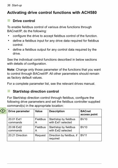
Activating drive control functions with ACH580
Drive control
To enable fieldbus control of various drive functions through BACnet/IP, do the following:
• configure the drive to accept fieldbus control of the function.
• define a fieldbus input for any drive data required for fieldbus control.
• define a fieldbus output for any control data required by the drive.
See the individual control functions described in below sections with details of configuration.
Note: Change only those parameter of the functions that you want to control through BACnet/IP. All other parameters should remain as factory default values.
For a complete parameter list, see the relevant drives manual.
Start/stop direction control
For Start/stop direction control through fieldbus, configure the following drive parameters and set the fieldbus controller supplied command(s) in the appropriate location:
Drive parameter Value Description BACnet access point
20.01 Ext1 commands
Fieldbus A
Start/stop by fieldbus with Ext1 selected
BV10
20.06 Ext2 commands
Fieldbus A
Start/stop by fieldbus with Ext2 selected
BV10
20.21 Direction Request Direction by fieldbus, if required
BV11

Start-up 37
Input reference select
The tables below show how to use the fieldbus to select the drive input references for frequency and speed control modes.
• For frequency control, set parameter 99.04 Motor control mode = Scalar (1) (default value for ACH580).
• For speed control, set parameter 99.04 Motor control mode = Vector (0)
Vector control has better accuracy than the scalar control, but vector control cannot be used in all situations. For information on control modes and reference scaling, see the drive manual.
The actual output values of the drive can be read from AV0...AV6, AV31 and AV32. For example, AV0 is output speed in rpm, AV1 is output frequency in Hz and AV31 is output speed in %.
Frequency reference
For using the fieldbus to provide input frequency references to the drive, configure the following drive parameters and set the fieldbus controller supplied reference word(s) in the appropriate location:
Drive parameter
Value Description BACnet access point
19.11 Ext1/Ext2 selection
2 = FBA A MCW bit
Reference set selection by fieldbus
BV13
28.11 Ext1 frequency ref1
3 = FBA ref1 1)
Frequency reference source 1
AV16
28.15 Ext2 frequency ref1
5 = FBA ref2 1))
Frequency reference source 2
AV17
46.02 Frequency scaling
50.00 Hz 1) 16-bit scaling of frequency-related parameters
AV16/AV17
50.04 FBA A ref1 type/50.05 FBA A ref2 type
0 = Speed or frequency5 = Frequency
References (1 or 2) type for scaling defined in parameter 46.02 Frequency scaling
AV16/AV17
1) As example

38 Start-up
Speed reference
For using the fieldbus to provide input speed references to the drive, configure the following drive parameters and set the fieldbus controller supplied reference word(s) in the appropriate location:
Miscellaneous drive control
To use the fieldbus for different drive control functions, configure the following drive parameters and set the fieldbus controller supplied command(s) in the appropriate location:
Drive parameter Value Description BACnet access point
19.11 Ext1/Ext2 selection
2 = FBA A MCW bit
Reference set selection by fieldbus
BV13
22.11 Ext1 speed ref1
3 =FBA ref1 1) Speed reference source 1
AV16
22.18 Ext2 speed ref1
5 =FBA ref2 1) Speed reference source 2
AV17
46.01 Speed scaling
1500 rpm 1) 16-bit scaling of speed-related parameters
AV16/AV17
50.04 FBA A ref1 type/50.05 FBA A ref2 type
0 = Speed or frequency 4 = Speed
References (1 or 2) type for scaling defined in parameter 46.02 Frequency scaling
AV16/AV17
1) As example
Drive parameter Value Description BACnet access point
20.40 Run permissive Fieldbus adapter
Run permission by fieldbus
BV12
20.01 Ext1 commands/20.06 Ext2 commands
Fieldbus A Fault reset by fieldbus BV14

Start-up 39
Relay output control
For relay output control through fieldbus,
• set the following drive parameters to select the source for the ROs
• program the drive for control through BACnet
• set the fieldbus controller supplied binary coded relay command(s) in the appropriate location.
20.41 Start interlock 1 Fieldbus adapter
Source for start interlock 1 is fieldbus
BV20
20.42 Start interlock 2 Fieldbus adapter
Source for start interlock 2 is fieldbus
BV21
Drive parameter
Value Description BACnet access point
10.24 RO1 source
RO/DIO control word bit0
Relay output 1 controlled by fieldbus
BO0
10.27 RO2 source
RO/DIO control word bit1
Relay output 2 controlled by fieldbus
BO1
10.30 RO3 source
RO/DIO control word bit2
Relay output 3 controlled by fieldbus
BO2
15.07 RO4 source
RO/DIO control word bit3
Relay output 4 controlled by fieldbus
BO3
15.10 RO5 source
RO/DIO control word bit4
Relay output 5 controlled by fieldbus
BO4
15.23 DO1 source
RO/DIO control word bit8
Digital output 1 controlled by fieldbus
BO5
Drive parameter Value Description BACnet access point

40 Start-up
Data point connections
The BACnet access points of the above relay output control parameters are in turn linked to the following parameters:
Analog output control
For analog output control through fieldbus, configure the following drive parameters and set the fieldbus controller supplied analog value(s) in the appropriate location.
For more information on scaling of analog outputs and inputs, see the ACH580 HVAC control program firmware manual (3AXD50000027537[English]).
BACnet access point
Drive parameter Description
BO0...BO5 10.99 RO/DIO control word
Storage parameter for relay output and digital outputs
Drive parameter
Value Description BACnet access point
13.12 AO1 source
AO1 data storage
Analog output 1 controlled by fieldbus
AO0
13.22 AO2 source
AO2 data storage
Analog output 2 controlled by fieldbus
AO1
13.17 AO1 source min
0.0 Minimum value of signal selected by parameter 13.12 AO1 source
AO0
13.18 AO1 source max
100.0 Maximum value of signal selected by parameter 13.12 AO1 source
AO0
13.27 AO2 source min
0.0 Minimum value of signal selected by parameter 13.22 AO2 source
AO1
13.28 AO2 source max
100.0 Maximum value of signal selected by parameter 13.22 AO2 source
AO1

Start-up 41
Data point connections
The BACnet access points in the above drive parameter connections are linked to the following data points:
PID control
For PID control through fieldbus, configure the following drive parameters and set the fieldbus controller supplied PID value(s) in the appropriate location:
Data point connections
The BACnet access points in the above drive parameter connections are linked to the following data points:
BACnet access point
Drive parameter Description
AO0 13.91 AO1 data storage
Storage parameter for AO1
AO1 13.92 AO2 data storage
Storage parameter for AO2
Drive parameter Value Description BACnet access point
40.08 Set 1 feedback 1 source
Feedback storage
Feedback 1 source data storage
AV43
40.09 Set 1 feedback 2 source
Feedback storage
Feedback 2 source data storage
AV43
40.16 Set 1 setpoint 1 source
Setpoint data storage
Setpoint 1 source data storage
AV42
40.17 Set 1 setpoint 2 source
Setpoint data storage
Setpoint 2 source data storage
AV42
BACnet access point
Drive parameter Description
AV43 40.91 Feedback data storage
Storage parameter for process feedback value

42 Start-up
Communication fault
BACnet has no built-in feature to detect communication timeout, because it is not a synchronous protocol. If communication timeouts are needed, you can use the following parameters to detect timeouts based on different packets and specifying the drive action.
Full timeout time is the sum of parameters 51.20 Timeout time and 50.03 FBA A comm loss tout.
AV42 40.92 Setpoint data storage
Storage parameter for process setpoint value
Drive parameter Value Description
51.21 Timeout mode 1 = Any packet2 = Control RW
Defines the message type that resets the timeout counter for detecting communication loss between the drive and the master.
51.20 Timeout time 0...65535 Sets the delay time for directing messages to the drive before a communication loss condition is declared.• If value is zero, the feature is
disabled.• If value is non-zero, the time is in
units of 100 ms. For example, a value of 300 is 30.0 seconds.
50.02 FBA A comm loss func
0 = No action1 = Fault2 = Last speed3 = Speed ref safe4 = Fault always5 = Warning
Selects how the drive reacts upon a fieldbus communication break. The time delay is defined by parameter 50.03 FBA A comm loss t out.
BACnet access point
Drive parameter Description

Start-up 43
Drive feedback
The inputs to the controller (drive outputs) have pre-defined meanings established by the protocol. This feedback does not required drive configuration.
The following table lists a sample of the feedback data. For a complete listing, see the input word/point/object listings in the chapter Communication protocol.
50.03 FBA A comm loss t out
0.3...6553.5 s Defines the time delay before the action defined by parameter 50.02 FBA A comm loss func is taken.
Drive parameter Description BACnet access point
01.01 Motor speed used
Estimated motor speed in RPM AV0
01.06 Output frequency
Estimated drive output frequency in Hz
AV1
01.11 DC voltage DC bus voltage AV2
01.13 Output voltage Calculated motor voltage in V AC AV3
01.07 Motor current Measured (absolute) motor current in A
AV4
01.10 Motor torque Motor torque in percent of the nominal motor torque
AV5
01.14 Output power Drive output power AV6
05.11 Inverter temperature
Estimated drive temperature in percent of fault limit
AV7
01.20 Inverter kWh counter
Amount of energy that has passed through the drive (in either direction) in full kilowatt-hours. Whenever the counter rolls over, 01.19 Inverter MWh counter is incremented. The minimum value is zero.
AV9
Drive parameter Value Description

44 Start-up
35.01 Motor estimated temperature
Displays the motor temperature as estimated by the internal motor thermal protection model
AV15
01.03 Motor speed %
Motor speed in percent of the synchronous motor speed.
AV31
01.50 Current hour kWh
Current hour energy consumption. This is the energy of the last 60 minutes (not necessarily continuous) the drive has been running, not the energy of a calendar hour. The value is set to the value before the power cycle when the drive is again up and running.
AV130
01.51 Previous hour kWh
Previous hour energy consumption. The value 01.50 Current hour kWh is stored here when its values has been cumulated for 60 minutes. The value is set to the value before the power cycle when the drive is again up and running.
AV131
01.52 Current day kWh
Current day energy consumption. The value 01.51 Previous hour kWh is stored here when its value has been cumulated for 24 hours. The value is set to the value before the power cycle when the drive is again up and running.
AV132
01.53 Previous day kWh
Previous day energy consumption. The value 01.52 Current day kWh is stored here when its value has been cumulated for 24 hours. The value is set to the value before the power cycle when the drive is again up and running
AV133
Drive parameter Description BACnet access point

Start-up 45
Fault queue for drive diagnostics
Faults specific to fieldbus control are listed below:
For general ACH580 diagnostics information, see the Diagnostics section in the ACH580 User’s manual.
Drive parameter Description BACnet access point
04.01 Tripping fault
Fault that caused the current trip AV18
04.11 Latest fault Code of the first stored (non-active) fault
AV19
04.12 2nd last fault
Code of the second stored (non-active) fault
AV20

46 Start-up
Starting up fieldbus communication for ACH580 drives
Follow these steps to setup fieldbus communication in ACH580 drives. For example of appropriate values, see Parameter setting examples (page 47).
1. Power up the drive.
2. Enable communication between the adapter module and the drive with parameter 50.01 FBA A enable.
3. Configure network settings with parameters 51.03...51.13.
4. Define the device object instance value with parameters 51.14 Device obj ID lo and 51.15 Device obj ID hi.
Note: The object instance value should be unique and in the range 1...4194303.
5. Define communication loss function to monitor the communication between fieldbus master and adapter module and between adapter module and drive:
• With parameters 51.20 and 51.21, set the timeout time and timeout mode.
• With parameter 50.03 FBA A comm loss t out, define the communication break reaction time.
• With parameter 50.02 FBA A comm loss func, select how the drive reacts to a fieldbus communication break.
6. With parameter 96.07 Parameter save manually, save the valid parameter values to permanent memory.
7. With parameter 51.27 FBA A par refresh, validate the settings made in parameter group 51.
8. Set the relevant drive control parameters to control the drive according to the application.

Start-up 47
Parameter setting examples
Frequency control
The table below shows an example of how to configure a basic frequency control application. Assume the rest of parameters are in default values.
ACH580 Drive parameter
Settings Description
50.01 FBA A enable 1 = Enable Enables communication between the drive and fieldbus adapter A, and specifies the slot the adapter is installed into.
51.01 FBA A type 47808 = BACnet1) Shows the fieldbus adapter type as detected by the drive.
51.03 Commrate 0 = Auto2) BACnet communication rate is negotiated automatically by the device.
51.04 IP configuration
1 = Static IP Configuration is obtained through parameter 51.05...51.13.
51.05 IP address 1 1922) First part of the IP address
51.06 IP address 2 1682) Second part of the IP address
51.07 IP address 3 02) Third part of the IP address
51.08 IP address 4 162) Last part of the IP address
51.09 Subnet CIDR 242) Sets the network mask as 255.255.255.0, allowing access only to the last subnet.
51.14 Device obj ID lo
512) Configures device object ID.
51.20 Comm loss time
3002) Sets the communication timeout as 30 seconds.

48 Start-up
51.21 Comm loss mode
1 = Any message2) The timeout feature monitors the updating of the Control word and Reference 1.
51.27 FBA A par refresh
1 = Configure Validates the FBIP-21 configuration parameter settings.
20.01 Ext1 commands
12 = Fieldbus A Selects the Fieldbus A interface as the source of start and stop commands for external control location 1.
28.11 Ext1 frequency ref1
4 = FB A ref1 Selects fieldbus reference 1 as the source for frequency reference 1.
1) Read-only or automatically detected/set2) Example
ACH580 Drive parameter
Settings Description

Communication protocol 49
7Communication protocol
Contents of this chapter
This chapter describes the BACnet/IP communication protocol for the adapter module.
BACnet/IP
BACnet/IP is a standard data communication protocol intended for supervision and control of building automation equipment.
The FBIP-21 adapter module supports the BACnet protocol version 1, revision 12 according to the ISO 16484-5:2014 standard.
BACnet/IP uses objects to abstract and represent information. An object is a collection of data elements called properties. The type of the object determines which properties are present. This information is accessed through standardized services, which can also be used to command BACnet devices.
The FBIP-21 adapter module acts as a server providing object data access for BACnet clients.
Prioritizing commands
Commandable objects consist of priority array property, which is used to store the command priority. If you do not define priority with a command (example, write service request), the priority defaults to the least important command.

50 Communication protocol
If the client no longer needs to control an object, it can relinquish the control by writing the priority property value as NULL. For more details, see the BACnet ISO standard 16484-5:2014.
Note: Priority arrays are not stored over the power cycle.
BACnet interoperability building blocks
The following BACnet interoperability building blocks that is collection of one or more services, are supported by FBIP-21:
Building block (short name)
Description
DS-RP-B Data Sharing – Read Property – B (Provider / Server)
DS-RPM-B Data Sharing – Read Property Multiple – B (Provider / Server)
DS-WP-B Data Sharing – Write Property – B (Provider / Server)
DS-WPM-B Data Sharing – Write Property Multiple – B (Provider / Server)
DM-DDB-B Device Management – Dynamic Device Binding – B (Provider / Server)
DM-DOB-B Device Management – Dynamic Object Binding – B (Provider / Server)
DM-DCC-B Device Management– Device Communication Control – B (Provider / Server), password is not required
DM-RD-B Device Management– Reinitialize Device B (Provider/Server), password is not required

Communication protocol 51
BACnet object list
The adapter module supports the BACnet objects listed below. The present value property of the object can be readable (R), writable (W) or commandable (C), i.e. writable with priority.
AI object
AO object
Object ID
Default object name
Description Minimum/Maximum preset value
Unit Present value access type
AI0 AI1-Monitor Indicates the input level of analog input 1.
0,100 % R
AI1 AI2-Monitor Indicates the input level of analog input 2.
0,100 % R
Object ID
Default object name
Description Minimum/Maximum preset value
Unit Present value access type
AO0 AO1-command
Controls analog output 1 (drive must be configured for BACnet control).
0,100 % C
AO1 AO2-command
Controls analog output 2 (drive must be configured for BACnet control).
0,100 % C

52 Communication protocol
AV object
Object ID
Default object name
Description Minimum/Maximum present value (information, depends on the drive parameter)
Unit Present value access type
AV0 Output-RPM
Motor speed 0, nominal speed rpm R
AV0 Output-RPM
Motor speed 0, nominal speed rpm R
AV1 Output-Freq
Output frequency
-500, 500 Hz R
AV2 DC-Voltage
DC bus voltage
0, 2000 V R
AV3 Output-Voltage
AC output voltage
0, 2000 V R
AV4 Output-Current
Output current of drive
0, nominal current A R
AV5 Output-Torque
Output torque of motor as a percentage of nominal torque
-1600, 1600 % R
AV6 Output-Power
Output power in kW
nominal power (+/-)
kW R
AV7 Operating-Temp-Range
Heatsink temperature
-40, 160 % R
AV9 Kilowatt-Hour-Meter-NR
Cumulative energy usage of the drive. This value cannot be reset.
0, 65535999999 kWh R

Communication protocol 53
AV15 Motor-Temp-Degrees-C
Motor temperature
-10, 200 °C R
AV16 Input-Reference-1
Speed setpoint 1
-150, 150 % C
AV17 Input-Reference-2
Speed setpoint 2
-150, 150 % C
AV18 Active-Fault
Active fault - No unit
R
AV19 Previous-Fault-1
Previous fault-1
- No unit
R
AV20 Previous-Fault-2
Previous fault-2
- No unit
R
AV21 AO1-Monitor
Output level of Analog Output 1
0, 100 % R
AV22 AO2-Monitor
Output level of Analog Output 2
0, 100 % R
AV23 Accel-1-Seconds
For frequency reference chain
0, 1800 s W
AV24 Decel-1-Seconds
For frequency reference chain
0, 1800 s W
AV29 Min-Speed
Minimum speed
-500, 500 Hz W
AV30 Max-Speed
Maximum speed
-500, 500 Hz W
Object ID
Default object name
Description Minimum/Maximum present value (information, depends on the drive parameter)
Unit Present value access type

54 Communication protocol
AV31 Output-Speed
Actual motor speed
-200, 200 % R
AV32 Output-Current-Range
Actual motor current
0, 200 % R
AV33 Max-Current
Max motor current
0, nominal current A W
AV40 LOOP-Feedback-Monitor
Loop controller feedback
0, 100 % R
AV41 LOOP-Setpoint-Monitor
Loop setpoint monitor
0, 100 % R
AV42 LOOP-Setpoint
Loop setpoint 0, 100 % C
AV43 LOOP-Feedback
Loop feedback
0, 100 % W
AV44 LOOP-Output
Loop output 0, 100 % R
AV45 LOOP-Gain
Loop gain 0.1, 100 No unit
W
AV46 LOOP-Integration-Time
Loop integration time
0, 3600 s W
AV49 LOOP-Deviation-Monitor
Loop controller deviation
0, 100 %
AV53 LOOP-1-Gain
Loop-1 gain 0.1, 100 No unit
W
AV54 LOOP-1-Integration-Time
Loop-1 integration time
0, 3600 s W
Object ID
Default object name
Description Minimum/Maximum present value (information, depends on the drive parameter)
Unit Present value access type

Communication protocol 55
AV130 Kilowatt-Hour-This-Hour
Kilowatt hour this hour
0, 3.40282347e38 kWh R
AV131 Kilowatt-Hour-Last-Hour
Kilowat hour during last hour
0, 3.40282347e38 kWh R
AV132 Kilowatt-Hour-This-Day
Kilowatt hour today
0, 3.40282347e38 kWh R
AV133 Kilowatt-Hour-Last-Day
Kilowatt hour last day
0, 3.40282347e38 kWh R
Object ID
Default object name
Description Minimum/Maximum present value (information, depends on the drive parameter)
Unit Present value access type

56 Communication protocol
BI object
Object ID
Default object name
Description Default active/Inactive text
Present value access type
BI0 RO1-Monitor Status of Relay Output 1 ON / OFF
R
BI1 RO2-Monitor Status of Relay Output 2 ON / OFF
R
BI2 RO3-Monitor Status of Relay Output 3 ON / OFF
R
BI3 RO4-Monitor Status of Relay Output 4 ON / OFF
R
BI4 RO5-Monitor Status of Relay Output 5 ON / OFF
R
BI5 DO1-Monitor Status of Digital Output 1 ON / OFF
R
BI6 DI1-Monitor Status of Digital Input 1 ON / OFF
R
BI7 DI2-Monitor Status of Digital Input 2 ON / OFF
R
BI8 DI3-Monitor Status of Digital Input 3 ON / OFF
R
BI9 DI4-Monitor Status of Digital Input 4 ON / OFF
R
BI10 DI5-Monitor Status of Digital Input 5 ON / OFF
R
BI11 DI6-Monitor Status of Digital Input 6 ON / OFF
R

Communication protocol 57
BO object
BV object
Object ID
Default object name
Description Default active/Inactive text
Present value access type
BO0 RO1-Command Output state of Relay 1 ON / OFF C
BO1 RO2-Command Output state of Relay 2 ON / OFF C
BO2 RO3-Command Output state of Relay 3 ON / OFF C
BO3 RO4-Command Output state of Relay 4 ON / OFF C
BO4 RO5-Command Output state of Relay 5 ON / OFF C
BO5 DO1-Command Output state of Digital Output 1
ON / OFF C
Object ID
Default object name
Description Default active/Inactive text
Present value access type
BV0 RUN-STOP-Monitor
Run status of drive RUN / STOP
R
BV1 Direction-Monitor
Rotational direction of the motor
REVERSE / FORWARD
R
BV2 OK-FAULT-Monitor
Actual fault status of drive
FAULT / OK R
BV3 EXT1-EXT2-Monitor
Actual control source EXT2 / EXT1
R
BV4 HAND-AUTO-Monitor
Actual operating mode HAND / AUTO
R
BV5 Warning-Monitor
Actual warning status WARNING / OK
R
BV7 Ready-Monitor
Actual ready status READY / NOT-READY
R

58 Communication protocol
BV8 At-Setpoint-Monitor
Actual at setpoint status YES / NO R
BV9 Enabled-Monitor
Actual run enabled status
ENABLE / DISABLE
R
BV10 RUN-STOP-Command
Command to start drive RUN / STOP
C
BV11 Direction-Command
Command to rotational direction
REVERSE / FORWARD
C
BV12 Run-Permissive-Command
Command to Run Permissive command
ENABLE / DISABLE
C
BV13 EXT1-EXT2-Command
Command to External 1 or External 2
EXT2 / EXT1
C
BV14 Fault-Reset-Command
Command to fault reset RESET / NO
W
BV18 Control-Override-Command
Command the drive into BACnet Control Override. In this mode BACnet acquires drive control from its normal source. Note: The HAND mode of the panel has priority over BACnet Control Override.
ON / OFF C
BV19 Control-Override-Monitor
Indicates if drive is placed in BACnet Control Override by commanding BV18. In this mode BACnet acquires drive control from its normal source. Note that HAND mode of the panel has priority over BACnet Control Override.
ON / OFF R
Object ID
Default object name
Description Default active/Inactive text
Present value access type
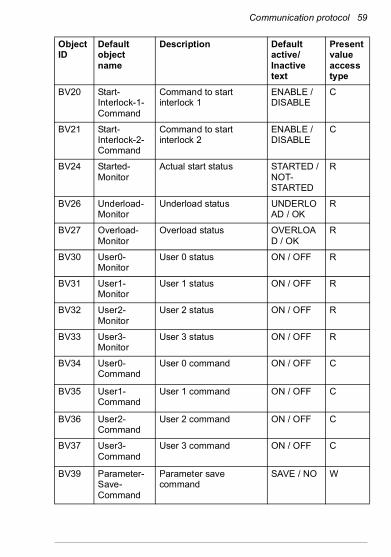
Communication protocol 59
BV20 Start-Interlock-1-Command
Command to start interlock 1
ENABLE / DISABLE
C
BV21 Start-Interlock-2-Command
Command to start interlock 2
ENABLE / DISABLE
C
BV24 Started-Monitor
Actual start status STARTED / NOT-STARTED
R
BV26 Underload-Monitor
Underload status UNDERLOAD / OK
R
BV27 Overload-Monitor
Overload status OVERLOAD / OK
R
BV30 User0-Monitor
User 0 status ON / OFF R
BV31 User1-Monitor
User 1 status ON / OFF R
BV32 User2-Monitor
User 2 status ON / OFF R
BV33 User3-Monitor
User 3 status ON / OFF R
BV34 User0-Command
User 0 command ON / OFF C
BV35 User1-Command
User 1 command ON / OFF C
BV36 User2-Command
User 2 command ON / OFF C
BV37 User3-Command
User 3 command ON / OFF C
BV39 Parameter-Save-Command
Parameter save command
SAVE / NO W
Object ID
Default object name
Description Default active/Inactive text
Present value access type

60 Communication protocol
Diagnostics 61
8Diagnostics
Contents of this chapter
This chapter explains how to trace faults with the status LEDs on the adapter module when the module is used for BACnet communication.
Fault and warning messages
For the fault and warning messages concerning the adapter module, see the drive firmware manual.

62 Diagnostics
LEDs
The adapter module is equipped with three bicolor diagnostic LEDs. The LEDs are described below.
Name Color Function
HOSTBlinking green
Establishing communication to host
Green Connection to host OK
Blinking red Communication to host lost temporarily
Flashing orange, alternating with the MODULE flashing orange
Internal file system error. The error may be cleared by cycling drive power. If the error persists, contact your local ABB representative.
MODULE Off There is no power applied to the device.
Flashing orange
Device is attempting to obtain IP configuration from the DHCP server.
Orange Device is executing Duplicate Address Detection.
Flashing green
Device is waiting for a BACnet request.
Green Device has received a BACnet request within the timeout period.
Flashing red Ethernet link is down.

Diagnostics 63
Red • Ethernet interface is disabled. • Duplicate Address Detection may have
detected a duplicate address. Check the IP configuration and either initiate a Fieldbus Adapter parameter refresh or cycle power to the drive.
or• Drive is not supported by FBIP-21.
Flashing orange, alternating with the HOST flashing orange
Internal file system error. The error may be cleared by cycling drive power. If the error persists, contact your local ABB representative.
Flashing red/green
Device is in boot mode, ready for firmware update (HOST led is Off).
NET Off BACnet link is down.
Flashing green
BACnet link is up at 100 Mbps.Flashing indicates activity on interface.
Flashing orange
BACnet link is up at 10 Mbps.Flashing indicates activity on interface.
Name Color Function

64 Diagnostics

Technical data 65
9Technical data
Contents of this chapter
This chapter contains the technical specifications of the adapter module and the BACnet link.
Layout diagram
The figure below shows the enclosure of the FBIP-21 BACnet/IP adapter module from the front and side.

66 Technical data
General conditions
BACnet link
Installation Into an option slot on the drive control unit
Degree of protection IP20
Ambient conditions The ambient conditions specified for the drive in its manuals are applicable.
Package Cardboard. Plastic wrapping: Antistatic air bubble sheet (PE).
Indicators Three bicolor LEDs (HOST, MODULE, NETWORK/NET)
Connectors A 20-pin connector to the drive RJ-45 connector to Ethernet (X1)RJ-45 connector for chaining another adapter module (X2)
Power supply +3.3 V ±5% max. 400 mA (supplied by the drive)
Compliance Complies with EMC standard EN 61800-3:2004Printed circuit board conformal coated
Compatible devices Ethernet Standard IEEE 802.3 and IEEE 802.3u devices
Medium 10BASE-TX or 100Base-TX with Auto-negotiation and Auto-MDIX (Auto-crossover)• Wiring: CAT5/6 UTP, CAT5/6 FTP, CAT5/6
STP• Connector: RJ-45• Termination: Internal• Maximum segment length: 100 m / 328 ft
Topology Bus or star.Max. 50 nodes allowed for FBIP-21 in a daisy chain topology.
Transfer rate 10 Mbps or 100 Mbps
Serial communication type
Half or full duplex
Protocol BACnet/IP

Further information
Product and service inquiriesAddress any inquiries about the product to your local ABB representative, quoting the type designation and serial number of the unit in question. A listing of ABB sales, support and service contacts can be found by navigating to www.abb.com/searchchannels.
Product trainingFor information on ABB product training, navigate to new.abb.com/service/training.
Providing feedback on ABB Drives manualsYour comments on our manuals are welcome. Navigate to new.abb.com/drives.manuals-feedback-form.
Document library on the InternetYou can find manuals and other product documents in PDF format on the Internet at www.abb.com/drives/documents.

Contact us
www.abb.com/drives www.abb.com/solar www.abb.com/windpowerwww.abb.com/drivespartners
3AXD50000028468 Rev A (EN) 2016-01-27