Fax: (210) 223-9589 -...
55
Transcript of Fax: (210) 223-9589 -...


Stantec Architecture Inc. 1344 South Flores Street Suite 201 San Antonio TX 78204-1672 Tel: (210) 223-9588 Fax: (210) 223-9589
ADDENDUM #2
12/12/2014
TO PLANS AND SPECIFICATIONS FOR NEW BAND HALL COLE HIGH SCHOOL FT. SAM HOUSTON ISD Ft. Sam Houston San Antonio, TX 12-12-14
NOTE:
If you have questions about this project, please contact:
Edward Rodriguez, Project Manager at Stantec Architecture.
210.223.9588
or
Wanira Magaloni, Designer
This Addendum is generally separated into sections for convenience; however, all contractors,
subcontractors, material suppliers and other involved parties shall be responsible for reading the entire
Addendum. Failure to list an item(s) in all affected sections of this Addendum does not relieve any
party affected from performing per instructions, provided the information is set forth one time
anywhere in the Addendum.
This document shall become attached to and part of the Construction Documents for the
aforementioned project.

BID DATE and TIME: December 18, 2014 at 2:30 pm DELIVER PROPOSALS TO:
Office of Stantec Architecture 1344 South Flores Street
Suite 201
San Antonio, Texas 78204
ATTACHMENTS: PREVAILING WAGE RATES
SPECIFICATION SECTION 123213 – WOOD CASE WORK
GENERAL ITEMS:
1. Liquated damages for the project are $500.00 per day.
2. The date of substantial completion is October 31, 2015
3. The current prevailing wage rates for the project is attached.
4. Refer to “Instructions to Offerors” RCSP ATTACHMENT B-OFFER
QUESTIONNAIRE– Item #16 CONFIRMATIONS A and B –
As of today’s date, the documents referenced in Item #16 – Confirmations - A and B
Appendix A1 “Standard Form of Agreement Between Owner and Contractor Where The Basis Of Payment Is A Stipulated Sum, AIA Document A101-2007, as amended by Owner”
And Appendix A2 “General Conditions of the Contract for Construction
AIA Document A201-2007, as amended by Owner”
Have not been made available to the architect for issuing to Offerors.
As a result, a response to Items “16 – Confirmation A and B” are not required at the time
a bid is submitted. These documents will be made available after the bid date of the
project. Once the above documents are issued, the apparent successful bidder will have
an opportunity to review them and provide comments or requested changes. The
comments and requested changes along with the final contract are subject to review and
approval of the Ft. Sam Houston ISD legal counsel.
Band Hall, Cole High School, Ft. Sam Houston ISD
Addendum #2 Page 2 of 4

SPECIFICATIONS: 6. Revisions to the Specifications are as follows:
ITEM SECTION DESCRIPTION S1-1 06 20 23 Interior Finish Carpentry Delete Section in its’ entirety. S1-2 07 41 23 Metal Wall Panels Part 2-Products-Basis of Design: Provide Metal wall panels as
described in the drawings on Sheet A201; The maximum length of panel “MP1” shall be 10’-0” long. The location of the joints for these panels will be coordinated during the shop drawing/submittal review of the project.
S1-3 08 41 00 Steel Acoustical Windows Delete Section in its’ entirety. S1-4 10 28 00 Toilet and Bath
Accessories CLARIFICATION: The Owner will provide Soap Dispensers, Paper Towel Dispenser and Trash Receptacles
S1-5 10 28 00 Toilet and Bath Accessories
CLARIFICATION: SANITARY NAPKIN DISPOSAL UNITS Surface Mounted Type: Fabricate of stainless steel with seamless exposed walls, tightly self closing top cover and locking bottom panel with continuous stainless steel piano hinge.
S1-6 12 32 13 Wood Case Work ADD this section in its’ entirety.
DRAWINGS: N/A.
ITEM SHEET NUMBER DESCRIPTION
Band Hall, Cole High School, Ft. Sam Houston ISD
Addendum #2 Page 3 of 4

END OF ADDENDUM #2
Band Hall, Cole High School, Ft. Sam Houston ISD
Addendum #2 Page 4 of 4
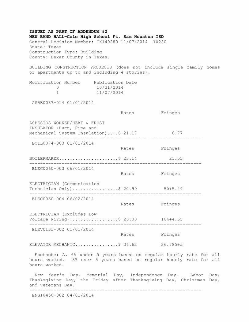
ISSUED AS PART OF ADDENDUM #2 NEW BAND HALL-Cole High School Ft. Sam Houston ISD General Decision Number: TX140280 11/07/2014 TX280 State: Texas Construction Type: Building County: Bexar County in Texas. BUILDING CONSTRUCTION PROJECTS (does not include single family homes or apartments up to and including 4 stories). Modification Number Publication Date 0 10/31/2014 1 11/07/2014 ASBE0087-014 01/01/2014 Rates Fringes ASBESTOS WORKER/HEAT & FROST INSULATOR (Duct, Pipe and Mechanical System Insulation)....$ 21.17 8.77 ---------------------------------------------------------------- BOIL0074-003 01/01/2014 Rates Fringes BOILERMAKER......................$ 23.14 21.55 ---------------------------------------------------------------- ELEC0060-003 06/01/2014 Rates Fringes ELECTRICIAN (Communication Technician Only).................$ 20.99 5%+5.49 ---------------------------------------------------------------- ELEC0060-004 06/02/2014 Rates Fringes ELECTRICIAN (Excludes Low Voltage Wiring)..................$ 26.00 10%+4.65 ---------------------------------------------------------------- ELEV0133-002 01/01/2014 Rates Fringes ELEVATOR MECHANIC................$ 36.62 26.785+a Footnote: A. 6% under 5 years based on regular hourly rate for all hours worked. 8% over 5 years based on regular hourly rate for all hours worked. New Year's Day, Memorial Day, Independence Day, Labor Day, Thanksgiving Day, the Friday after Thanksgiving Day, Christmas Day, and Veterans Day. ---------------------------------------------------------------- ENGI0450-002 04/01/2014

Rates Fringes POWER EQUIPMENT OPERATOR Cranes......................$ 34.85 9.85 ---------------------------------------------------------------- IRON0066-013 12/01/2013 Rates Fringes IRONWORKER, STRUCTURAL...........$ 19.80 5.95 ---------------------------------------------------------------- IRON0084-011 06/15/2014 Rates Fringes IRONWORKER, ORNAMENTAL...........$ 22.02 6.35 ---------------------------------------------------------------- PLUM0142-009 07/01/2014 Rates Fringes HVAC MECHANIC (HVAC Electrical Temperature Control Installation Only).......$ 30.40 10.10 HVAC MECHANIC (HVAC Unit Installation Only)...............$ 30.40 10.10 PIPEFITTER (Including HVAC Pipe Installation)...............$ 30.40 10.10 PLUMBER (Excludes HVAC Pipe Installation)....................$ 30.40 10.10 ---------------------------------------------------------------- SFTX0669-002 07/31/2014 Rates Fringes SPRINKLER FITTER (Fire Sprinklers)......................$ 26.36 16.52 ---------------------------------------------------------------- SHEE0067-004 04/01/2014 Rates Fringes Sheet metal worker Excludes HVAC Duct Installation................$ 25.60 13.54 HVAC Duct Installation Only.$ 25.60 13.54 ---------------------------------------------------------------- SUTX2014-006 07/21/2014 Rates Fringes BRICKLAYER.......................$ 22.15 0.00 CARPENTER (Acoustical Ceiling Installation Only)...............$ 17.83 0.00 CARPENTER (Form Work Only).......$ 13.63 0.00 CARPENTER, Excludes Acoustical Ceiling Installation, Drywall Hanging, Form Work, and Metal

Stud Installation................$ 16.86 4.17 CAULKER..........................$ 15.00 0.00 CEMENT MASON/CONCRETE FINISHER...$ 22.27 5.30 DRYWALL FINISHER/TAPER...........$ 13.81 0.00 DRYWALL HANGER AND METAL STUD INSTALLER........................$ 15.18 0.00 ELECTRICIAN (Low Voltage Wiring Only).....................$ 20.39 3.04 IRONWORKER, REINFORCING..........$ 12.27 0.00 LABORER: Common or General......$ 10.75 0.00 LABORER: Mason Tender - Brick...$ 11.88 0.00 LABORER: Mason Tender - Cement/Concrete..................$ 12.00 0.00 LABORER: Pipelayer..............$ 11.00 0.00 LABORER: Roof Tearoff...........$ 11.28 0.00 LABORER: Landscape and Irrigation.......................$ 8.00 0.00 OPERATOR: Backhoe/Excavator/Trackhoe.......$ 15.98 0.00 OPERATOR: Bobcat/Skid Steer/Skid Loader................$ 14.00 0.00 OPERATOR: Bulldozer.............$ 14.00 0.00 OPERATOR: Drill.................$ 14.50 0.00 OPERATOR: Forklift..............$ 12.50 0.00 OPERATOR: Grader/Blade..........$ 23.00 5.07 OPERATOR: Loader................$ 12.79 0.00 OPERATOR: Mechanic..............$ 18.75 5.12 OPERATOR: Paver (Asphalt, Aggregate, and Concrete).........$ 16.03 0.00 OPERATOR: Roller................$ 12.00 0.00

PAINTER (Brush, Roller and Spray), Excludes Drywall Finishing/Taping.................$ 13.07 0.00 ROOFER...........................$ 12.00 0.00 TILE FINISHER....................$ 11.32 0.00 TILE SETTER......................$ 14.94 0.00 TRUCK DRIVER: Dump Truck........$ 12.39 1.18 TRUCK DRIVER: Flatbed Truck.....$ 19.65 8.57 TRUCK DRIVER: Semi-Trailer Truck............................$ 12.50 0.00 TRUCK DRIVER: Water Truck.......$ 12.00 4.11 ---------------------------------------------------------------- WELDERS - Receive rate prescribed for craft performing operation to which welding is incidental. ================================================================ Unlisted classifications needed for work not included within the scope of the classifications listed may be added after award only as provided in the labor standards contract clauses (29CFR 5.5 (a) (1) (ii)). ---------------------------------------------------------------- The body of each wage determination lists the classification and wage rates that have been found to be prevailing for the cited type(s) of construction in the area covered by the wage determination. The classifications are listed in alphabetical order of "identifiers" that indicate whether the particular rate is union or non-union. Union Identifiers An identifier enclosed in dotted lines beginning with characters other than "SU" denotes that the union classification and rate have found to be prevailing for that classification. Example: PLUM0198-005 7/01/2011. The first four letters , PLUM, indicate the international union and the four-digit number, 0198, that follows indicates the local union number or district council number where applicable , i.e., Plumbers Local 0198. The next number, 005 in the example, is an internal number used in processing the wage determination. The date, 07/01/2011, following these characters is the effective date of the most current negotiated rate/collective bargaining agreement which would be July 1, 2011 in the above example. Union prevailing wage rates will be updated to reflect any changes in the collective bargaining agreements governing the rates.
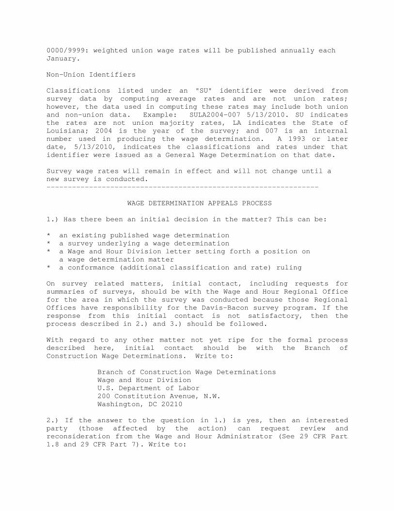
0000/9999: weighted union wage rates will be published annually each January. Non-Union Identifiers Classifications listed under an "SU" identifier were derived from survey data by computing average rates and are not union rates; however, the data used in computing these rates may include both union and non-union data. Example: SULA2004-007 5/13/2010. SU indicates the rates are not union majority rates, LA indicates the State of Louisiana; 2004 is the year of the survey; and 007 is an internal number used in producing the wage determination. A 1993 or later date, 5/13/2010, indicates the classifications and rates under that identifier were issued as a General Wage Determination on that date. Survey wage rates will remain in effect and will not change until a new survey is conducted. ---------------------------------------------------------------- WAGE DETERMINATION APPEALS PROCESS 1.) Has there been an initial decision in the matter? This can be: * an existing published wage determination * a survey underlying a wage determination * a Wage and Hour Division letter setting forth a position on a wage determination matter * a conformance (additional classification and rate) ruling On survey related matters, initial contact, including requests for summaries of surveys, should be with the Wage and Hour Regional Office for the area in which the survey was conducted because those Regional Offices have responsibility for the Davis-Bacon survey program. If the response from this initial contact is not satisfactory, then the process described in 2.) and 3.) should be followed. With regard to any other matter not yet ripe for the formal process described here, initial contact should be with the Branch of Construction Wage Determinations. Write to: Branch of Construction Wage Determinations Wage and Hour Division U.S. Department of Labor 200 Constitution Avenue, N.W. Washington, DC 20210 2.) If the answer to the question in 1.) is yes, then an interested party (those affected by the action) can request review and reconsideration from the Wage and Hour Administrator (See 29 CFR Part 1.8 and 29 CFR Part 7). Write to:

Wage and Hour Administrator U.S. Department of Labor 200 Constitution Avenue, N.W. Washington, DC 20210 The request should be accompanied by a full statement of the interested party's position and by any information (wage payment data, project description, area practice material, etc.) that the requestor considers relevant to the issue. 3.) If the decision of the Administrator is not favorable, an interested party may appeal directly to the Administrative Review Board (formerly the Wage Appeals Board). Write to: Administrative Review Board U.S. Department of Labor 200 Constitution Avenue, N.W. Washington, DC 20210 4.) All decisions by the Administrative Review Board are final. ================================================================
END OF GENERAL DECISION
NEW BAND HALL STANTEC PROJ. NO. 214000210 COLE HIGH SCHOOL FT. SAM HOUSTON INDEPENDENT SCHOOL DISTRICT ISSUED AS PART OF ADDENDUM 2 SECTION 12 32 13 - WOOD CASEWORK PART 1 - GENERAL 1.1 RELATED DOCUMENTS
A. Drawings and general provisions of Contract, including General and Supplementary Conditions and Division 1 Specification Sections, apply to Work of this Section.
1.2 DESCRIPTION OF WORK
A. Extent of wood casework is shown on drawings.
B. Work includes the fabrication and installation of standard furniture components of base cabinets, wall cabinets, storage cabinets, wardrobe cabinets, tables, shelf units, and other units as indicated.
C. This Section does not include custom millwork. Refer to Division 6 Specification Sections for custom millwork
requirements. Casework is distinguished from custom millwork specified in Division 6 Sections by model numbers which correspond to predetermined cabinet designs. Refer to the plans for casework model numbers.
1.3 DEFINITIONS
A. Interior architectural woodwork includes wood furring, blocking, shims, and hanging strips for installing
woodwork items, unless concealed within other construction before woodwork installation.
B. AWI-QSI: American Woodwork Institute – Quality Standards Illustrated.
C. AWI-AWS: American Woodwork Institute – Architectural Wood Standards. D. Balanced Construction: To achieve balanced construction panels should be absolutely symmetrical from the
centerline, i.e., use materials on either side, which contract or expand, or are moisture permeable, at the same rate.
E. Particleboard Core Plywood: From AWI-QSI and AWI-AWS, plywood where the core is particleboard. Particleboard Core Plywood is not used on or allowed on the job.
F. Medium Density Fiberboard (MDF) Core Plywood: From AWI-QSI and AWI-AWS, plywood where the core is MDF. MDF Core Plywood is not used on or allowed on the job.
G. Plywood: From AWI-QSI and AWI-AWS, Veneer Core (three or more layers of wood glued together) - For this Job, 7-ply minimum core shall be required and will be the only form of plywood recognized as plywood. Wood glued to one or both sides of Particleboard or MDF is by definition, for this job, not a form of plywood. These non-plywood panel products will not be allowed on this job unless otherwise indicated within this specification.
H. Base: The bottom support of a cabinet; the substructure on which the top of the cabinet stands or rests; occurs at cabinets mounted on the floor. The Cabinet Base shall be a water resistant wood or other material structure upon which the top of the cabinet shall be built. It shall be provided from the floor surface to a height that is four (4) inches above the finished floor. The base shall be provided at all faces/sides of all cabinets. For rectilinear and four sided cabinets, the base shall be provided at the front, left side, right side and rear of the cabinet. Where cabinets are more than four sided, and there is not a single front, left side, right side or rear, the base shall be provided at all the sides of the polygon shaped cabinet. Where the cabinet has a curved footprint, the bottom of the curved panel, and all the other sides of the cabinet shall be provided with a base. At cabinets with less than four sides, all the sides shall be provided with a base.
I. More definitions are in Part 2.
J. For the purposes of this specification and project:
1. Thermoset Decorative Overlay (TDO): Melamine. 2. High-Pressure Decorative Laminate (HPDL): Plastic Laminate other than Melamine. 3. CLS: Thin Plastic Laminate used exclusively for cabinet liner or other “hidden from view” applications,
unless otherwise indicated. WOOD CASEWORK 12 32 13 - 1 ©2013 SHW Group Architects | Engineers | Planners

NEW BAND HALL STANTEC PROJ. NO. 214000210 COLE HIGH SCHOOL FT. SAM HOUSTON INDEPENDENT SCHOOL DISTRICT ISSUED AS PART OF ADDENDUM 2 1.4 SUBMITTALS
A. Product Data: Submit manufacturer's data and installation instructions for each type of furniture unit.
B. Samples: Samples will be reviewed by Architect for color, texture, and pattern only. Compliance with other specified requirements is exclusive responsibility of Contractor. Comply with AWS Section 1 – Submittals, and, in addition, the following:
1. Submit 6 inches x 6 inches samples of specified finishes, including top material. 2. Submit section of countertop showing top, front edge, and backsplash construction. 3. Submit both hinged and sliding door samples.
C. Shop Drawings: Comply with AWS Section 1 – Submittals, and, in addition, the following:
1. Submit one copy of Shop Drawings to AWI Quality Certification Program for review. 2. Shop Drawings to display AWS certified compliance label on first page. 3. Coordinate shop drawings with other work involved. 4. Show locations and sizes of cutouts and holes for plumbing fixtures, faucets, soap dispensers, and
other items installed in wood casework. 1.5 QUALITY ASSURANCE
A. Single Source Responsibility: Provide wood casework with tops and accessories manufactured or furnished by same furniture company for single responsibility.
B. Catalog Standards: Manufacturer's catalog numbers may be shown on drawings for convenience in identifying
certain cabinet work. Unless modified by notation on drawings or otherwise specified, catalog description for indicated number constitutes requirements for each such cabinet.
C. The use of catalog numbers, and specific requirements set forth in drawings and specifications, are not intended
to preclude the use of any other acceptable manufacturer's product or procedures which may be equivalent, but are given for purpose of establishing standard of design and quality for materials, construction and workmanship.
D. Quality Standard: Unless otherwise indicated, comply with Architectural Woodwork Institute, Architectural
Woodwork Manufacturers Association of Canada, Woodwork Institute “Architectural Woodwork Standards” (AWS) for grades of interior architectural woodwork, construction, finishes, and other requirements.
1. Provide AWS Quality Certification Program certificates indicating that woodwork, including installation,
complies with requirements of grades specified. 2. The Contractor, upon award of the Work, shall register the Work under this Section with the AWI Quality
Certification Program 800-449-8811 www.awiqcp.org 1.6 DELIVERY, STORAGE, AND HANDLING
A. Deliver wood casework only after wet operations in building are completed.
B. Store completed wood furniture in a ventilated place, protected from the weather, with relative humidity therein of 50 percent or less at 70 deg. F (22 deg. C).
C. Protect finished surfaces from soiling and damage during handling and installation. Keep covered with
polyethylene film or other protective covering. PART 2 - PRODUCTS 2.1 WOOD CASEWORK
A. General Cabinet Construction Requirements:
1. Cabinet bases (see definition of base) shall be of dimensional lumber. 2. Frames, side panels, and structural parts of the cabinets shall be of plywood and or dimensional
lumber. WOOD CASEWORK 12 32 13 - 2 ©2013 SHW Group Architects | Engineers | Planners

NEW BAND HALL STANTEC PROJ. NO. 214000210 COLE HIGH SCHOOL FT. SAM HOUSTON INDEPENDENT SCHOOL DISTRICT ISSUED AS PART OF ADDENDUM 2
3. Doors, shelves, and drawer fronts may have their substrate of any wood material <except particleboard> <and> <except> <medium density and heavy density fiberboards>.
4. All fixed shelves shall be full shelf thickness “stop dado” jointed to their supports. The full depth of the stop dado joint shall begin no more than 1-1/2 inches from the face of the shelf and end at the back of the shelf. Such joint shall be continuous.
B. Definitions: The following definitions apply to wood casework units:
1. Exposed portions of casework (Finish Surfaces) include surfaces visible when doors and drawers are
closed. Bottoms of cases more than 4'-0" above floor shall be considered as exposed. Visible members in open cases or behind glass doors also shall be considered as exposed portions.
2. Semi-exposed portions of casework includes those members behind opaque doors, such as shelves, divisions, interior faces of ends, case back, drawer sides, backs and bottoms, and back face of doors. Tops of cases 6'-6" or more above floor shall be considered semi-exposed.
3. Concealed portions of casework include sleepers, web frames, dust panels, and other surfaces not usually visible after installation.
C. Wood Construction: 1. HARDBOARD IS UNACCEPTABLE FOR USE AS A SUBSTRATE. MELAMINE IS UNACCEPTABLE
FOR USE AS A FINISH SURFACE. 2. PARTICLEBOARD CORE PLYWOOD AND ANY OF IT’S VARIANTS SHALL NOT BE ALLOWED IN
THE CASEWORK CONSTRUCTION. 3. MEDIUM DENSITY FIBERBOARD (MDF) CORE PLYWOOD AND ANY OF IT’S VARIANTS SHALL NOT
BE ALLOWED IN THE CASEWORK CONSTRUCTION. 4. PARTICLEBOARD AND ANY OF IT’S VARIANTS SHALL NOT BE ALLOWED IN THE CASEWORK
CONSTRUCTION. 5. MEDIUM DENSITY FIBERBOARD (MDF) AND ANY OF IT’S VARIANTS SHALL NOT BE ALLOWED IN
THE CASEWORK CONSTRUCTION. D. Exposed Materials: Do not use exposed faces of lighter-than-average color joined with exposed faces of
darker-than-average color. Do not use two adjacent faces which are noticeably dissimilar in grain, figure, and natural character markings.
1. Solid Lumber: Clear, dry, premium grade red oak, free from defects and selected for compatible grain
and color. 2. Plywood Face Veneer: Same species as exposed solid lumber, clear, selected for grain and color
compatible with exposed solid lumber, no defects. Provide solid crossbandings without voids. Edgeband exposed edges with solid wood of same species as face veneer.
E. Semi-Exposed Materials:
1. Solid Lumber: Dry, sound, selected to eliminate appearance defects. Any species of hardwood, or
softwood of similar color and grain to exposed portions. 2. Plywood: Hardwood, ANSI/HPMA HP, Good Grade (1), or softwood ANSI/VOL. PROD. STD. PS-1,
Group 1, A-A, INT, of species to match color and grain of exposed members.
F. Concealed Members:
1. Solid Lumber or Plywood: Any species, with no defects affecting strength or utility.
G. Glass: ASTM C 1048, Kind FT (fully tempered), Condition A, Type I, Class 1, quality q3 (Glazing select).
H. Clear Wood Finish:
I. General: Provide complete factory finish to comply with chemical and physical resistance requirements. After installation, touch up or refinish damaged portions equal to original factory finish.
J. Preparation: Sand exposed and semi-exposed components, using machine and hand methods. Machine marks,
cross sanding, tool marks or other surface blemishes are not acceptable.
K. Exposed Portions: Carefully sand finishes after each surface treatment. Apply finishes as follows:
1. Sealer coat, if required. 2. Stain, to match color selected, if required. 3. Mineral filler, for open grained wood, if required.
WOOD CASEWORK 12 32 13 - 3 ©2013 SHW Group Architects | Engineers | Planners

NEW BAND HALL STANTEC PROJ. NO. 214000210 COLE HIGH SCHOOL FT. SAM HOUSTON INDEPENDENT SCHOOL DISTRICT ISSUED AS PART OF ADDENDUM 2
4. Multiple coats of highly chemical resistant finish, heat dried and sanded between each coat to produce a smooth, satin luster free of imperfections.
L. Semi-Exposed Portions: Apply sealer coat, colored to match exposed portions, and follow with heavy application
of clear, water repellant finish coat to provide a smooth, washable surface.
M. Concealed Portions: One heavy coat of water repellant finish.
N. Manufacturers: Subject to compliance with requirements, manufacturers offering products which may be incorporated in the Work include the following:
1. Cabinets by Design 770.418.1200 http://216.120.237.3/~cabinets/ 2. [Imperial Mill & Fixtures Inc. 361-883-4630] 3. Kewaunee Scientific Corporation 704-873-7202 www.kewaunee.com 4. [South Texas Woodmill, Inc. 956-831-3304 www.stx-woodmill.com ] 5. Terrill Manufacturing Co. Inc. 325-655-7133 www.terrillmfg.com
2.2 CASEWORK HARDWARE AND ACCESSORIES
A. Provide manufacturer's standard, satin finish hardware units, unless otherwise indicated.
B. Hinges: Institutional type, 5 knuckle. Provide one pair for doors less than 4 ft. high and 1-1/2 pair for doors over 4 ft.
C. Pulls: Solid metal, for drawers and swing doors, mounted with 2 screws fastened from back. For sliding doors,
provide recessed flush pulls. Provide 2 pulls for drawers over 24 inches wide.
D. Door Catches: Dual self-aligning permanent magnet type. Provide 2 catches on doors over 4 ft. high.
E. Drawer Slides: Designed to permit easy removal, and yet prevent inadvertant drawer removal. Provide on all drawers, equal to, or better than K&V #1300.
F. Label Holders: Provide where indicated, size to receive standard label cards approximately 1 inch x 2 inches
nominal size, finished to match other exposed hardware.
G. Drawer and Cupboard Locks: Half-mortise type, 5-pin tumbler and dead bolt, round cylinder only exposed, brass with plated finish.
H. Sliding Door Hardware Sets: Manufacturer's standard, to suit type and size of sliding door units.
I. Cabinet Base Molding: Extruded rubber, color as indicated on the color schedule for rubber base, 4 inches high.
Provide on exposed sides and fronts of floor-mounted cabinets.
J. Leg Shoes: Extruded vinyl or rubber, black, open bottom type.
K. Adjustable Shelf Supports:
1. Shelf Standards: 255 Series, nickel-plated, Knape & Vogt Manufacturing Company 800-253-1561 www.knapeandvogt.com
2. Shelf Brackets: 256 Series, nickel-plated, Knape & Vogt Manufacturing Company 800-253-1561 www.knapeandvogt.com
2.3 FABRICATION
A. Fabricate wood furniture to dimensions, profiles, and details shown.
B. Assemble units in the shop in as large components as practicable to minimize field jointing.
C. Install hardware uniformly and precisely after final finishing is complete. Set hinges snug and flat in mortises unless otherwise indicated. Turn screws to flat seat. Adjust and align hardware so that moving parts operate freely and contact points meet accurately. Allow for final field adjustment after installation.
WOOD CASEWORK 12 32 13 - 4 ©2013 SHW Group Architects | Engineers | Planners

NEW BAND HALL STANTEC PROJ. NO. 214000210 COLE HIGH SCHOOL FT. SAM HOUSTON INDEPENDENT SCHOOL DISTRICT ISSUED AS PART OF ADDENDUM 2 2.4 TOPS AND ACCESSORIES
A. Tops, Box Curbs, Splash Rim: Provide smooth, clean, exposed tops and edges, in uniform plane free of defects. Make exposed edges and corners uniformly rounded.
B. Top Sizes: Furnish tops in maximum practicable lengths.
C. Top Thickness: Maintain 1-1/4 inch thickness with tolerance not exceeding plus or minus 1/32 inch. Provide front
and end overhang of 1 inch over base cabinets, formed with continuous drip groove on under surface 1/2 inch from edge.
D. Top Laminate: HGS (0.050 inch nominal thickness).
E. Plastic Laminate: Provide plastic laminate sheet color as referenced by Architect from manufacturer's
designations for products of this type, complying with NEMA LD-3. Use general purpose grade 0.050 inch thick for flat tops, shop-bonded with fully waterproof bond glue to 3/4 inch thick sub-top hardwood faced 7-ply minimum, veneer core plywood or phenolic resin bonded particleboard. At countertops with sinks or other plumbed fixtures or accessories use only shop-bonded with fully waterproof bond glue to 3/4" thick sub-top hardwood faced 7-ply, minimum, Veneer Core Plywood or water resistant particleboard. OVERLAY PLYWOOD AND REGULAR PARTICLEBOARD ARE UNACCEPTABLE ADJACENT TO PLUMBING FIXTURES AND FIXTURE ACCESSORIES. Smooth sand surfaces to which plastic laminate is to be bonded. Apply standard phenolic backing sheet to back of panels. Build up exposed edges of tops to 1-1/4 inch thickness. Self-edge exposed edges of top, splash, and openings with same plastic laminate used for tops. Unless otherwise indicated, top and back splash one piece.
PART 3 - EXECUTION 3.1 CASEWORK INSTALLATION
A. Quality Standard: Install wood casework to comply with AWS for the items specified in Part 2 of this Section
for type of wood casework involved.
B. Install plumb, level, true and aligned with no distortions. Shim as required, using concealed shims. Where casework abuts other finished work, scribe and apply filler strips for accurate fit with fasteners concealed where practicable.
C. Base Cabinets: Set cabinets straight, plumb, and level. Adjust sub-tops within 1/16 inch of a single plane. Fasten
each individual cabinet to floor at toe space, with fasteners spaced 24 inches o.c. Bolt continuous cabinets together. Secure individual cabinets with not less than 2 fasteners into floor, where they do not adjoin other cabinets.
D. Where required, assemble units into one integral unit with joints flush, tight, and uniform. Align similar adjoining
doors and drawers to a tolerance of 1/16 inch.
E. Wall Cabinets: Securely fasten to solid supporting material, not plaster, lath, or wallboard. Anchor, adjust, and align wall cabinets as specified for base cabinets.
1. Reinforcement of stud walls to support wall-mounted cabinets will be done during wall erection by trade
involved, but responsibility for accurate location and sizing of reinforcement is part of this work.
F. Adjust casework and hardware so that doors and drawers operate smoothly without warp or bind. Lubricate operating hardware as recommended by manufacturer.
G. Keying: Key cabinet locks alike <within each room and differently from room to room> <throughout the areas
receiving new cabinets>. Provide 4 master keys which can operate all cabinet locks provided and installed] 3.2 INSTALLATION OF TOPS
A. Field Jointing: Where practicable, make in same manner as factory jointing using dowels, splines, adhesives, and
fasteners recommended by manufacturer. Locate field joints as shown on accepted shop drawings, factory prepared so there is no job site processing of top and edge surfaces.
B. Fastenings: Use concealed clamping devices for field joints, except for natural stone, composition stone and
epoxy tops, located within 6" of front, at back edges and at intervals not exceeding 24 inches. Tighten in WOOD CASEWORK 12 32 13 - 5 ©2013 SHW Group Architects | Engineers | Planners

NEW BAND HALL STANTEC PROJ. NO. 214000210 COLE HIGH SCHOOL FT. SAM HOUSTON INDEPENDENT SCHOOL DISTRICT ISSUED AS PART OF ADDENDUM 2
accordance with manufacturer's instructions to exert a constant, heavy clamping pressure at joints. Except for natural stone, composition stone and epoxy tops, secure tops to cabinets with "Z"-type fasteners or equivalent, using 2 or more fasteners at each front, end, and back.
C. Workmanship: Abut top and edge surfaces in one true plane, with internal supports placed to prevent any
deflection. Provide flush hairline joints in top units using clamping devices. At stone-type material joints, use manufacturer's recommended adhesives and holding devices to provide joint widths not more than 1/16" wide at any location, completely filled and flush with abutting edges.
D. After installation, carefully dress joints smooth, remove any surface scratches, clean and polish entire surface.
E. Provide holes and cutouts as required for mechanical and electrical service fixtures.
F. Provide scribe mouldings for closures at junctures of top, curb and splash with walls as recommended by
manufacturer for materials involved. Use permanently elastic sealing compound recommended by manufacturer. 3.3 INSTALLATION OF ACCESSORIES
A. Install in a precise manner in accordance with manufacturer's directions. Turn screws to a flat seat; do not drive.
Adjust moving parts to operate freely without excessive bind. 3.4 CLEANING AND PROTECTION
A. Repair or remove and replace defective work as directed upon completion of installation.
B. Clean shop-finished surfaces, touch-up as required, and remove or refinish damaged or soiled areas, as
acceptable to Architect.
C. Protection: Advise Contractor of procedures and precautions for protection of materials and installed wood casework from damage by work of other trades.
END OF SECTION 12 32 13
WOOD CASEWORK 12 32 13 - 6 ©2013 SHW Group Architects | Engineers | Planners

Stantec Architecture Inc. 1344 South Flores Street Suite 201 San Antonio TX 78204-1672 Tel: (210) 223-9588 Fax: (210) 223-9589
ADDENDUM #3
12/14/2014
TO PLANS AND SPECIFICATIONS FOR NEW BAND HALL COLE HIGH SCHOOL FT. SAM HOUSTON ISD Ft. Sam Houston San Antonio, TX 12-14-14
NOTE:
If you have questions about this project, please contact:
Edward Rodriguez, Project Manager at Stantec Architecture.
210.223.9588
or
Wanira Magaloni, Designer
This Addendum is generally separated into sections for convenience; however, all contractors,
subcontractors, material suppliers and other involved parties shall be responsible for reading the entire
Addendum. Failure to list an item(s) in all affected sections of this Addendum does not relieve any
party affected from performing per instructions, provided the information is set forth one time
anywhere in the Addendum.
This document shall become attached to and part of the Construction Documents for the
aforementioned project.

BID DATE and TIME: December 18, 2014 at 2:30 pm DELIVER PROPOSALS TO:
Office of Stantec Architecture 1344 South Flores Street
Suite 201
San Antonio, Texas 78204
ATTACHMENTS: SPECIFICATION SECTION 097223 – ACOUSTICAL WALL PANELS SPECIFICATION SECTION 105113 – METAL LOCKERS SPECIFICATION SECTION 122414 – ELECTRIC ROLLER SHADES QUESTIONS FROM BIDDERS
GENERAL ITEMS:
1. N/A
SPECIFICATIONS: 6. Revisions to the Specifications are as follows:
ITEM SECTION DESCRIPTION S1-1 097223 – ACOUSTICAL WALL
PANELS ADD this section in its entirety.
S1-2 105113 – METAL LOCKERS ADD this section in its entirety. S1-3 122414 – ELECTRIC ROLLER
SHADES ADD this section in its entirety.
DRAWINGS: N/A.
ITEM SHEET NUMBER DESCRIPTION
END OF ADDENDUM #2
Band Hall, Cole High School, Ft. Sam Houston ISD
Addendum #3 Page 2 of 2

NEW BAND HALL STANTEC PROJ. NO. 214000210 COLE HIGH SCHOOL FT. SAM HOUSTON INDEPENDENT SCHOOL DISTRICT ISSUED AS PART OF ADDENDUM 3 SECTION 097223 - ACOUSTICAL WALL PANELS PART 1 - GENERAL 1.1 RELATED DOCUMENTS:
A. Drawings and general provisions of Contract, including General and Supplementary Conditions and Division-1 Specification sections, apply to work of this section.
1.2 SUMMARY:
A. Extent of acoustical wall panels is shown on drawings.
a. Utilize where shown on drawings
b. Refer to drawings for acoustical panel thickness. 1.3 SUBMITTALS:
A. Product Data: Submit manufacturer's technical data for each type of acoustical wall panel required.
B. Samples for Initial Selection Purposes: Submit manufacturer's standard size swatches of material indicated as facing for acoustical wall panels showing full range of colors, textures, and patterns available for each type of panel and facing material required.
C. Samples for Verification Purposes: Submit 12" square samples of each type of acoustical wall panel required and
in each color, texture and pattern indicated or selected for facing materials. Include representative samples of in-stallation devices and accessories.
D. Certified Test Reports: Submit test data from an independent testing agency, acceptable to authorities having
jurisdiction, evidencing that panel assemblies comply with requirements indicated for fire performance characteristics.
E. Certificates: Submit certificates from manufacturers of acoustical wall panels attesting that their products comply
with specified requirements including those for fire performance characteristics. 1.4 QUALITY ASSURANCE:
A. Fire Performance Characteristics: Provide acoustical wall panels, with surface-burning characteristics as indicated below, which have been determined by testing assemblies of identical materials and construction according to ASTM E 84 by a testing organization acceptable to authorities having jurisdiction.
1. Flame Spread: 25 or less. 2. Smoke Developed: 450 or less.
1.5 PRODUCT HANDLING:
A. Protect acoustical wall panels from excessive moisture in shipment, storage, and handling. Deliver in unopened bundles and store in a dry place with adequate air circulation. Do not deliver material to building until "wet work" such as concrete and plaster have been completed and cured to a condition of equilibrium.
1.6 PROJECT CONDITIONS:
A. Do not begin installation until spaces to receive acoustical wall panels have been enclosed and maintained at approximately the same humidity and temperature conditions as planned for occupancy. Maintain temperature and humidity as recommended by panel manufacturer.
ACOUSTICAL WALL PANELS 097723 - 1

NEW BAND HALL STANTEC PROJ. NO. 214000210 COLE HIGH SCHOOL FT. SAM HOUSTON INDEPENDENT SCHOOL DISTRICT ISSUED AS PART OF ADDENDUM 3 1.7 EXTRA MATERIALS:
A. Deliver extra materials to Owner. Furnish extra materials described below matching products installed, packaged with protective covering for storage and identified with appropriate labels:
1. Acoustical Wall Panels: Furnish quantity of full size units equal to 2.0 percent of the amount installed.
PART 2 - PRODUCTS 2.1 ACOUSTICAL WALL PANELS, GENERAL:
A. Fabricate panels to sizes and configurations indicated; attach facing materials to cores to produce installed panels with visible surfaces fully covered and free from wrinkles, sags, blisters, seams, adhesive or other foreign matter.
1. Fabricate back-mounted panels in factory to exact sizes required to fit wall surfaces based on field
measurements of completed substrates indicated to receive wall panels. 2. Sound Diffuser Panels shall be type: Barrel Shaped Diffuser panels 3. Standard Sound Diffuser panels shall be constructed of a laminate of one layer of fiberglass
mat saturated with five retardant polyester resin with a top coat of a white gel-coat molded in a one piece special barrel shape.
B. Sound Absorption Performance: Provide acoustical wall panels with minimum noise reduction coefficients (NRC) indicated as determined by testing per ASTM C 423 for mounting type specified under individual product requirements.
1. Gelcoat Finish N.R.C. = .20, in accordance with ASTM test procedures #C-423 Type A Mounting.
C. Colors, Textures and Patterns: Where manufacturer's standard material is indicated, provide acoustical wall
panels faced with manufacturer's material complying with the following requirements:
1. Provide color, texture and pattern to match that indicated by reference by manufacturers' standard designation for these characteristics.
2.2 BACK-MOUNTED ACOUSTICAL WALL PANELS:
A. Impact Resistance: Provide impact resistant panel facings for panels indicated to be installed at a height of 9'-0" above finish floor and less.
B. Back-Mounted Edged-Reinforced Acoustical Wall Panels with Impact-Resistant Face: Provide manufacturers
standard panel construction consisting of facing material laminated to front, edges and back border of 2-ply molded glass fiber board core, with edges chemically hardened to reinforce panel perimeter against warpage and damage, and complying with the following requirements:
STRUCTURAL FRAMING USING WOOD, PLASTIC, OR METAL WILL NOT BE ACCEPTED!
1. Thickness/Core Density: 2"/7 lbs. per cu. ft. a. Octave Band Center Frequencies (Hz)/Nominal Absorption Coefficient: Panels shall have the
following nominal octave band absorption coefficients within a tolerance of plus or minus 5% when mounted directly on a hard surface:
1.) 125/0.40 2.) 250/0.98 3.) 500/1.00 4.) 1000/1.00 5.) 2000/1.00 6.) 4000/1.00
ACOUSTICAL WALL PANELS 097723 - 2

NEW BAND HALL STANTEC PROJ. NO. 214000210 COLE HIGH SCHOOL FT. SAM HOUSTON INDEPENDENT SCHOOL DISTRICT ISSUED AS PART OF ADDENDUM 3
C. Back-Mounted Edge-Reinforced Acoustical Wall Panels: Manufacturers standard panel construction consisting of facing material laminated to front, edges and back border of molded glass fiber board core, with edges chemically hardened to a minimum depth of 1/8" to reinforce panel perimeter against warpage and damage, and complying with the following requirements:
1. Thickness/Core Density: 2" Fabric Wrapped Panels / 7 lbs. per cu. ft. a. Octave Band Center Frequencies (Hz)/Nominal Absorption Coefficient: Panels shall have the
following nominal octave band absorption coefficients within a tolerance of plus or minus 5% when mounted directly on a hard surface:
1.) 125/0.40 2.) 250/0.98 3.) 500/1.00 4.) 1000/1.00 5.) 2000/1.00 6.) 4000/1.00
2. Facing Materials: Manufacturers of fabric:
a. Design Basis: Knoll Textiles, 1-866-565-5858, www.knolltextiles.com b. Guilford of Maine, 1-800-544-0200, www.guilfordofmaine.com c. or approved equal. Each panel shall be faced with approved fabric bonded directly to the panel face and returned at the edges to the back of the panel. Provide panels with flat, wrinkle-free surface, and tailored corners.
a. Panel Size: As indicated. b. Edge Detail: Beveled. c. Corner Detail: Square. d. Colors: Knoll Textiles: W1020/7 Steel and W1020/1 Pearl
4. Back-Mounting Accessories: Manufacturer's standard or recommended accessories for securely
mounting panels of type and size indicated to substrates provided and complying with the following requirements:
5. Mechanically-Mounted Edge-Reinforced Panels: Metal panel clip and base support bracket system and
consisting of 2-part panel clips, with one part of each clip mechanically attached to back of panel and the other to wall substrate, designed to support panels laterally; and base support brackets designed to support full weight of panels; with both designed to allow panel removal.
D. Available Manufacturers/Products: Subject to compliance with requirements, products which may be incorporated
in the work include the following:
1. Accutrack Systems 770-941-9009. www.accutracksystems.com 2. Acoustical Resources, Inc. 877-522-6507 www.acousticalresources.com 3. AVL Systems, Inc. 800-228-7842 www.avlonline.com 4. Capaul, Inc. 800-876-5884 www.bpb-na.com 5. Conwed, Inc. 6. Decoustics. 800-387-3809 www.decoustics.com 7. Golterman & Sabo, 800-737-0307 www.golterman.com 8. Interior Acoustics, Inc. 800-221-0580 9. Kinetics Noise Control, 800-959-1229 www.kineticsnoise.com 10. Lamvin. 800-446-6329 http://www.lamvin.com 11. Peabody/Hard Side. 12. Quiet Technology Systems 480-632-9234 http://www.qtechsys.com/ 13. Vicracoustics. 14. Wall Technology... 800 359 3312 www.walltechnology.com 15. Woodard Contract, Inc. 16. Sound Concepts Canada, Inc.
ACOUSTICAL WALL PANELS 097723 - 3

NEW BAND HALL STANTEC PROJ. NO. 214000210 COLE HIGH SCHOOL FT. SAM HOUSTON INDEPENDENT SCHOOL DISTRICT ISSUED AS PART OF ADDENDUM 3 PART 3 - EXECUTION 3.1 INSTALLATION:
A. Install acoustical wall panels in locations indicated with vertical surfaces and edges plumb, top edges level, and in alignment with other panels, scribed to fit adjoining work accurately at borders and at penetrations. Comply with panel manufacturer's printed instructions for installation of panels using type of mounting accessories indicated or, if none indicated, as recommended by manufacturer.
B. Remove and replace panels which are damaged and are unacceptable to Architect.
END OF SECTION 097723
ACOUSTICAL WALL PANELS 097723 - 4

NEW BAND HALL STANTEC PROJ. NO. 214000210 COLE HIGH SCHOOL FT. SAM HOUSTON INDEPENDENT SCHOOL DISTRICT ISSUED AS PART OF ADDENDUM 3 SECTION 10 51 13 - METAL LOCKERS PART 1 - GENERAL 1.1 RELATED DOCUMENTS
A. Drawings and general provisions of the Contract, including General and Supplementary Conditions and
Division 1 Specification Sections, apply to this Section. 1.2 SUMMARY
A. This Section includes the following:
1. All-welded, standard metal lockers. 2. Benches.
B. Related Sections include the following:
1. Division 6 Section "Rough Carpentry" for furring, blocking, and shims required for installing metal lockers
and concealed within other construction before metal locker installation. 1.3 DEFINITIONS
A. Uncoated Steel Sheet Thicknesses: Indicated as the minimum thicknesses.
1.4 SUBMITTALS
A. Product Data: Include construction details, material descriptions, dimensions of individual components and
profiles, and finishes for each type of metal locker and bench. B. Shop Drawings: Include plans, elevations, sections, details, and attachments to other work.
1. Show sloping tops, filler panels, recess trim and other accessories where applicable. 2. Include locker identification system and sequential numbering.
C. Samples for Verification: For metal lockers and benches, in manufacturer's standard sizes.
D. Qualification Data: For Installer.
E. Maintenance Data: For adjusting, repairing, and replacing locker doors and latching mechanisms to include in
maintenance manuals. F. Warranty: Special warranty specified in this Section.
1.5 QUALITY ASSURANCE
A. Installer Qualifications: An authorized representative of metal locker manufacturer for installation and
maintenance of units required for this Project. B. Source Limitations: Obtain metal lockers and accessories through one source from a single manufacturer.
C. Product Options: Drawings indicate size, profiles, and dimensional requirements of metal lockers and are
based on the specific system indicated. Refer to Division 1 Section "Product Requirements."
1. Do not modify intended aesthetic effects, as judged solely by Architect, except with Architect's approval. If modifications are proposed, submit comprehensive explanatory data to Architect for review.
METAL LOCKERS 10 51 13 - Page 1 of 7

NEW BAND HALL STANTEC PROJ. NO. 214000210 COLE HIGH SCHOOL FT. SAM HOUSTON INDEPENDENT SCHOOL DISTRICT ISSUED AS PART OF ADDENDUM 3
D. Regulatory Requirements: Where metal lockers are indicated to comply with accessibility requirements, comply with the U.S. Architectural & Transportation Barriers Compliance Board's "Americans with Disabilities Act (ADA), Accessibility Guidelines for Buildings and Facilities (ADAAG)”, and with the Texas Department of Licensing and Regulation “Texas Accessibility Standards (TAS)”.
1. Provide hardware that does not require tight grasping, pinching, or twisting of the wrist, and that operates
with a force of not more than 5 lbf (22.2 N). 1.6 DELIVERY, STORAGE, AND HANDLING
A. Do not deliver metal lockers until spaces to receive them are clean, dry, and ready for metal locker installation.
B. Deliver master and control keys and combination control charts to Owner by registered mail or overnight
package service. 1.7 PROJECT CONDITIONS
A. Field Measurements: Verify the following by field measurements before fabrication and indicate measurements
on Shop Drawings:
1. Concealed framing, blocking, and reinforcements that support metal lockers before they are enclosed. 2. Recessed openings.
B. Established Dimensions: Where field measurements cannot be made without delaying the Work, establish
recessed opening dimensions and proceed with fabricating metal lockers without field measurements. Coordinate wall and floor construction to ensure that actual recessed opening dimensions correspond to established dimensions.
1.8 COORDINATION
A. Coordinate size and location of concrete and concrete masonry bases for metal lockers.
B. Coordinate sizes and locations of framing, blocking, furring, reinforcements, and other related units of Work
specified in other Sections to ensure that metal lockers can be supported and installed as indicated. 1.9 WARRANTY
A. Special Warranty: Manufacturer's standard form in which manufacturer agrees to repair or replace
components of metal lockers that fail in materials or workmanship, excluding finish, within specified warranty period.
1. Failures include, but are not limited to, the following:
a. Structural failures. b. Faulty operation of latches and other door hardware.
2. Damage from deliberate destruction and vandalism is excluded. 3. Warranty Period for All-Welded Metal Lockers: 10 years from date of Substantial Completion.
1.10 EXTRA MATERIALS
A. Furnish extra materials described below, before construction begins, that match products installed and that are
packaged with protective covering for storage and identified with labels describing contents.
1. Full-size units of the following metal locker hardware items equal to 5 percent of amount installed for each type and finish installed, but no fewer than 5 units.
a. Locks. b. Identification plates. c. Hooks.
METAL LOCKERS 10 51 13 - Page 2 of 7

NEW BAND HALL STANTEC PROJ. NO. 214000210 COLE HIGH SCHOOL FT. SAM HOUSTON INDEPENDENT SCHOOL DISTRICT ISSUED AS PART OF ADDENDUM 3 PART 2 - PRODUCTS 2.1 MANUFACTURERS
A. Manufacturers: Subject to compliance with requirements, manufacturers offering products which may be
incorporated in the Work include, but are not limited to, the following:
1. ASI Storage Solutions Inc. 901-312-6195 www.asilockers.com 2. DeBourgh Manufacturing Co. 800-328-8829 www.debourgh.com 3. List Industries, Inc. 800-776-1342 www.listindustries.com 4. Lyon Metal Products, Inc. 800-323-0082 www.lyonmetal.com 5. Penco 800-562-1000 www.pencoproducts.com 6. Republic Storage Systems, LLC 800-477-1255 www.republicstorage.com 7. WEC Manufacturing 901-366-0093 http://itswec.com/
2.2 MATERIALS
A. Cold-Rolled Steel Sheet: ASTM A 1008, Commercial Steel (CS) Type B, suitable for exposed applications.
B. Expanded Metal: ASTM F 1267, Type II (flattened), Class I, 3/4-inch (19-mm) steel mesh, with at least 70
percent open area.
C. Fasteners: Zinc- or nickel-plated steel, slotless-type exposed bolt heads, and self-locking nuts or lock washers for nuts on moving parts.
D. Anchors: Select material, type, size, and finish required for secure anchorage to each substrate.
1. Provide nonferrous-metal or hot-dip galvanized anchors and inserts on inside face of exterior walls and elsewhere as required for corrosion resistance.
2. Provide toothed-steel or lead expansion sleeves for drilled-in-place anchors. 2.3 ALL-WELDED, STANDARD METAL LOCKERS
A. Body: Assembled by welding body components together. Fabricate from unperforated, cold-rolled steel sheet with thicknesses as follows:
1. Tops, Bottoms, and Sides: 0.0528 inch (1.35 mm) thick. 2. Backs: 0.0428 inch (1.1 mm) thick. 3. Shelves: 0.0528 inch (1.35 mm) thick, with double bend at front and single bend at sides and back.
B. Frames: Channel formed; fabricated from 0.0528 inch (1.35 mm) thick, cold-rolled steel sheet; lapped and
factory welded at corners; with top and bottom main frames factory welded into vertical main frames. Form continuous, integral door strike full height on vertical main frames.
C. Locker Base: Structural channels, formed from 0.0528 inch (1.35 mm) thick, cold-rolled steel sheet; welded to
front and rear of side-panel frames. D. Doors: One-piece; fabricated from 0.0677 inch (1.7 mm) thick, cold-rolled steel sheet; formed into channel
shape with double bend at vertical edges, and with right-angle single bend at horizontal edges.
1. Reinforcement: Manufacturer's standard reinforcing angles, channels, or stiffeners for doors more than 15 inches (381 mm) wide; welded to inner face of doors.
2. Door Style: Vented panel as follows:
a. Louvered Vents: Not less than six louver openings at top and bottom for single-tier lockers; three louver openings at top and bottom for double-tier lockers; and two louver openings at top and bottom, or three louver openings at top or bottom for multiple-tier lockers.
METAL LOCKERS 10 51 13 - Page 3 of 7

NEW BAND HALL STANTEC PROJ. NO. 214000210 COLE HIGH SCHOOL FT. SAM HOUSTON INDEPENDENT SCHOOL DISTRICT ISSUED AS PART OF ADDENDUM 3
E. Hinges: Self-closing; welded to door and attached to door frame with not less than 2 factory-installed rivets per
hinge that are completely concealed and tamper resistant when door is closed; fabricated to swing 180 degrees.
1. Knuckle Hinges: Steel, full loop, 5 or 7 knuckles, tight pin; minimum 2 inches (51 mm) high. Provide not
less than 3 hinges for each door more than 42 inches (1067 mm) high. 2. Continuous Hinges: Manufacturer's standard, steel continuous hinge. 3. Hinges: Manufacturer's standard, steel continuous or knuckle type.
F. Recessed Door Handle and Latch: Stainless-steel cup with integral door pull, recessed so locking device does
not protrude beyond face of door; pry resistant.
1. Multipoint Latching: Finger-lift latch control designed for use with built-in combination locks or padlocks; positive automatic and prelocking.
a. Latch Hooks: Equip doors 48 inches (1219 mm) and higher with 3 latch hooks and doors less than 48
inches (1219 mm) high with 2 latch hooks; fabricated from minimum 0.1116 inch (2.8 mm) thick steel; welded to full-height door strikes; with resilient silencer on each latch hook.
b. Latching Mechanism: Manufacturer's standard rattle-free latching mechanism and moving components isolated to prevent metal-to-metal contact and incorporating a prelocking device that allows locker door to be locked while door is open and then closed without unlocking or damaging lock or latching mechanism.
2. Single-Point Latching: Nonmoving latch hook designed with steel padlock loop that projects through
recessed cup and is finished to match metal locker body.
a. Latch Hook: Equip each door with 1 latch hook, fabricated from minimum 0.1116 inch (2.8 mm) thick steel; welded midway up full-height door strike; with resilient silencer.
3. Latching: Manufacturer’s standard, multi- or- single- point.
G. Combination Padlocks: Key-controlled, three-number dialing combination locks; capable of five combination
changes. H. Equipment: Equip each metal locker with identification plate and the following, unless otherwise indicated:
1. Single-Tier Units: Shelf, one double-prong ceiling hook, and two single-prong wall hooks. 2. Double-Tier Units: One double-prong ceiling hook and two single-prong wall hooks. 3. Multiple-Tier Units: One double-prong ceiling hook. 4. Coat Rods: As indicated on Drawings.
I. Accessories:
1. Continuous Sloping Tops: Fabricated from minimum 0.0428 inch (1.1 mm) thick, cold-rolled steel sheet;
approximately 20-degree pitch.
a. Closures: Vertical-end type.
2. Filler Panels: Fabricated from 0.0428 inch (1.1 mm) thick, cold-rolled steel sheet. 3. Boxed End Panels: Fabricated from 0.0528 inch (1.35 mm) thick, cold-rolled steel sheet.
J. Finish: Baked enamel or powder coat.
1. Color(s): As selected by Architect from manufacturer's standard color range.
2.6 BENCHES
METAL LOCKERS 10 51 13 - Page 4 of 7

NEW BAND HALL STANTEC PROJ. NO. 214000210 COLE HIGH SCHOOL FT. SAM HOUSTON INDEPENDENT SCHOOL DISTRICT ISSUED AS PART OF ADDENDUM 3
A. General: Provide benches fabricated by same manufacturer as metal lockers. B. Bench Tops: Manufacturer's standard 1-piece units, of the following material, minimum 9-1/2 inches (240 mm)
wide by 1-1/4 inches (32 mm) thick, with rounded corners and edges:
1. Laminated maple with one coat of clear sealer on all surfaces, and one coat of clear lacquer on top and sides.
C. Fixed Pedestals: Manufacturer's standard supports, with predrilled fastener holes for attaching bench top and
anchoring to floor, complete with fasteners and anchors, and as follows:
1. Tubular Steel: 1-1/4 inch (32 mm) diameter steel tubing, with 0.1265 inch (3.2 mm) thick steel flanges welded at top and base; with zinc-plated finish; anchored with exposed fasteners.
2.7 FABRICATION
A. General: Fabricate metal lockers square, rigid, and without warp; with metal faces flat and free of dents or
distortion. Make exposed metal edges free of sharp edges and burrs, and safe to touch.
1. Form body panels, doors, shelves, and accessories from one-piece steel sheet, unless otherwise indicated.
2. Provide fasteners, filler plates, supports, clips, and closures as required for a complete installation. B. Unit Principle: Fabricate each metal locker with an individual door and frame; individual top, bottom, and back;
and common intermediate uprights separating compartments. C. All-Welded Construction: Factory preassemble metal lockers by welding all joints, seams, and connections,
with no bolts, nuts, screws, or rivets used in assembly of main locker groups. Factory weld main locker groups into one-piece structures. Grind exposed welds flush.
D. Hooks: Manufacturer's standard ball-pointed type, aluminum or steel; zinc plated.
E. Coat Rods: Fabricated from 1 inch (25 mm) diameter steel; chrome finished.
F. Identification Plates: Manufacturer's standard etched, embossed, or stamped aluminum plates; with numbers
and letters at least 3/8 inch (9 mm) high. G. Continuous Sloping Tops: Fabricated in lengths as long as practicable, without visible fasteners at splice
locations; finished to match lockers.
1. Sloped top corner fillers, mitered. H. Filler Panels: Fabricated in an unequal leg angle shape; finished to match lockers. Provide slip joint filler angle
formed to receive filler panel. I. Boxed End Panels: Fabricated with 1 inch (25 mm) wide edge dimension, and designed for concealing
fasteners and holes at exposed ends of nonrecessed metal lockers; finished to match lockers.
1. Provide one-piece panels for double-row (back-to-back) locker ends. 2.8 STEEL SHEET FINISHES
A. General: Comply with NAAMM's "Metal Finishes Manual for Architectural and Metal Products" for
recommendations for applying and designating finishes. B. Factory finish steel surfaces and accessories except stainless-steel and chrome-plated surfaces.
1. Surface Preparation: Clean surfaces of dirt, oil, grease, mill scale, rust, and other contaminants that could
impair paint bond. Use manufacturer's standard methods. 2. Baked-Enamel Finish: Immediately after cleaning, pretreating, and phosphatizing, apply manufacturer's
standard thermosetting baked-enamel finish. Comply with paint manufacturer's written instructions for application, baking, and minimum dry film thickness.
METAL LOCKERS 10 51 13 - Page 5 of 7
NEW BAND HALL STANTEC PROJ. NO. 214000210 COLE HIGH SCHOOL FT. SAM HOUSTON INDEPENDENT SCHOOL DISTRICT ISSUED AS PART OF ADDENDUM 3 PART 3 - EXECUTION 3.1 EXAMINATION
A. Examine walls, floors, and support bases, with Installer present, for compliance with requirements for
installation tolerances and other conditions affecting performance of Work.
1. For the record, prepare written report, endorsed by Installer, listing conditions detrimental to performance of Work.
B. Proceed with installation only after unsatisfactory conditions have been corrected.
3.2 INSTALLATION
A. General: Install level, plumb, and true; shim as required, using concealed shims.
1. Anchor locker runs at ends and at intervals recommended by manufacturer, but not more than 36 inches
(910 mm) o.c. Install anchors through backup reinforcing plates, channels, or blocking as required to prevent metal distortion, using concealed fasteners.
2. Anchor single rows of metal lockers to walls near top and bottom of lockers. 3. Anchor back-to-back metal lockers to floor.
B. All-Welded Metal Lockers: Connect groups of all-welded metal lockers together with standard fasteners, with
no exposed fasteners on face frames. C. Equipment and Accessories: Fit exposed connections of trim, fillers, and closures accurately together to form
tight, hairline joints, with concealed fasteners and splice plates.
1. Attach hooks with at least two fasteners. 2. Attach door locks on doors using security-type fasteners. 3. Identification Plates:
a. Attach plates to each locker door, near top, centered, with at least two aluminum rivets. b. Attach plates to upper shelf of each open-front metal locker, centered, with a least two aluminum
rivets.
4. Attach recess trim to recessed metal lockers with concealed clips. 5. Attach filler panels with concealed fasteners. Locate fillers panels where indicated on Drawings. 6. Attach sloping top units to metal lockers, with closures at exposed ends. 7. Attach boxed end panels with concealed fasteners to conceal exposed ends of nonrecessed metal lockers.
D. Benches: Provide not less than 2 pedestals for each bench, uniformly spaced not more than 72 inches (1830
mm) apart. Securely fasten tops of pedestals to undersides of bench tops, and anchor bases to floor. 3.3 ADJUSTING, CLEANING, AND PROTECTION
A. Clean, lubricate, and adjust hardware. Adjust doors and latches to operate easily without binding. Verify that
integral locking devices operate properly.
B. Protect metal lockers and benches from damage, abuse, dust, dirt, stain, or paint. Do not permit metal locker or bench use during construction.
C. Clean metal locker interiors and exterior surfaces.
D. Clean bench surfaces.
METAL LOCKERS 10 51 13 - Page 6 of 7

NEW BAND HALL STANTEC PROJ. NO. 214000210 COLE HIGH SCHOOL FT. SAM HOUSTON INDEPENDENT SCHOOL DISTRICT ISSUED AS PART OF ADDENDUM 3
E. Touch up marred finishes, or replace metal lockers or benches that cannot be restored to factory-finished appearance. Use only materials and procedures recommended or furnished by metal locker manufacturer.
END OF SECTION 10 51 13
METAL LOCKERS 10 51 13 - Page 7 of 7

NEW BAND HALL STANTEC PROJ. NO. 214000210 COLE HIGH SCHOOL FT. SAM HOUSTON INDEPENDENT SCHOOL DISTRICT ISSUED AS PART OF ADDENDUM 3
SECTION 12 24 14 – ELECTRIC ROLLER SHADES
PART 1 - GENERAL
1.1 RELATED DOCUMENTS
A. Drawings and general provisions of the Contract, including General and Supplementary Conditions and Division 1 Specification Sections, apply to this Section.
1.2 SUMMARY
A. This Section includes roller shades and motorized shade operators. These shades are only installed at the Library.
B. Related Sections include the following: 1. Division 26 Sections for electrical service and connections for motor operators, controls, limit
switches, and other powered devices and for system disconnect switches for motorized shade operation. Refer to addendum 1.
1.3 SUBMITTALS
A. Product Data: For each type of product indicated. Include styles, material descriptions, construction details, dimensions of individual components and profiles, features, finishes, and operating instructions.
1. Motorized Shade Operators: Include operating instructions. 2. Motors: Show nameplate data, ratings, characteristics, and mounting arrangements.
B. Shop Drawings: Show location and extent of roller shades. Include elevations, sections, details, and dimensions not shown in Product Data. Show installation details, mountings, attachments to other work, operational clearances, and relationship to adjoining work.
1. Motorized Shade Operators: Show locations and details for installing operator components, switches, and controls. Indicate motor size, electrical characteristics, drive arrangement, mounting, and grounding provisions.
2. Wiring Diagrams: Power, system, and control wiring.
C. Coordination Drawings: Reflected ceiling plans, drawn to scale, on which the following items are shown and coordinated with each other, based on input from installers of the items involved:
1. Ceiling suspension system members and attachment to building structure. 2. Ceiling-mounted or penetrating items including light fixtures, air outlets and inlets, speakers,
sprinklers, recessed shades, and special moldings at walls, column penetrations, and other junctures of acoustical ceilings with adjoining construction.
3. Shade mounting assembly and attachment. 4. Size and location of access to shade operator, motor and adjustable components. 5. Minimum Drawing Scale: 1/4 inch = 1 foot (1:48).
D. Samples for Initial Selection: For each colored component of each type of shade indicated.
1. Include similar Samples of accessories involving color selection.
E. Samples for Verification: 1. For the following products:
ELECTRIC ROLLER SHADES 12 24 14 - 1

NEW BAND HALL STANTEC PROJ. NO. 214000210 COLE HIGH SCHOOL FT. SAM HOUSTON INDEPENDENT SCHOOL DISTRICT ISSUED AS PART OF ADDENDUM 3
a. Shade Material: Not less than 12-inch- (300-mm-) square section of fabric, from dye lot used for the Work, with specified treatments applied. Show complete pattern repeat. Mark top and face of material.
F. Window Treatment Schedule: For roller shades. Use same designations indicated on Drawings.
G. Product Certificates: For each type of roller shade, signed by product manufacturer.
H. Product Test Reports: For each type of roller shade.
I. Maintenance Data: For roller shades to include in maintenance manuals. Include the following:
1. Methods for maintaining roller shades and finishes. 2. Precautions about cleaning materials and methods that could be detrimental to fabrics, finishes, and
performance. 3. Operating hardware. 4. Motorized shade operator.
1.4 QUALITY ASSURANCE
A. Installer Qualifications: Fabricator of products.
B. Source Limitations: Obtain roller shades through one source from a single manufacturer.
C. Fire-Test-Response Characteristics: Provide roller shade band materials with the fire-test-response characteristics indicated, as determined by testing identical products per test method indicated below by UL or another testing and inspecting agency acceptable to authorities having jurisdiction:
1. Flame-Resistance Ratings: Passes NFPA 701.
D. Electrical Components, Devices, and Accessories: Listed and labeled as defined in NFPA 70, Article 100, by a testing agency acceptable to authorities having jurisdiction, and marked for intended use.
E. Product Standard: Provide roller shades complying with WCMA A 100.1.
F. Mockups: Build mockups to verify selections made under sample submittals and to demonstrate aesthetic effects and set quality standards for materials and execution.
1. Approved mockups may become part of the completed Work if undisturbed at time of Substantial Completion.
1.5 DELIVERY, STORAGE AND HANDLING
A. Deliver shades in factory packages, marked with manufacturer and product name, fire-test-response characteristics, lead-free designation, and location of installation using same designations indicated on Drawings and in a window treatment schedule.
1.6 PROJECT CONDITIONS
A. Environmental Limitations: Do not install roller shades until construction and wet and dirty finish work in spaces, including painting, is complete and ambient temperature and humidity conditions are maintained at the levels indicated for Project when occupied for its intended use.
B. Field Measurements: Where roller shades are indicated to fit to other construction, verify dimensions of other construction by field measurements before fabrication and indicate measurements on Shop Drawings. Allow clearances for operable glazed units' operation hardware throughout the entire operating range. Notify
ELECTRIC ROLLER SHADES 12 24 14 - 2

NEW BAND HALL STANTEC PROJ. NO. 214000210 COLE HIGH SCHOOL FT. SAM HOUSTON INDEPENDENT SCHOOL DISTRICT ISSUED AS PART OF ADDENDUM 3
Architect of discrepancies. Coordinate fabrication schedule with construction progress to avoid delaying the Work.
PART 2 - PRODUCTS
2.1 ROLLER SHADES
A. Available Products: Subject to compliance with requirements, products that may be incorporated into the Work include, but are not limited to, the following:
B. Products: Subject to compliance with requirements, provide one of the following: 1. Draper Inc. 800-238-7999 www.draperinc.com . 2. Hunter Douglas, Inc.; Hunter Douglas Window Fashions Division. 3. Levolor; Levolor-Kirsch Window Fashions; a Newell Rubbermaid Company. 4. MechoShade Systems, Inc. 5. Nysan Shading Systems Ltd. 6. Solarfective Products Limited. 800-421-5578 www.solarfective.com/ 7. Springs Window Fashions Division, Inc. Graber. 800-327-9798 www.springs.com
C. Shade Band Material: PVC-coated fiberglass.
1. Fabric Width: As indicated by size of windows on Drawings - field verify once windows are installed. 2. Bottom Hem: Straight.
D. Rollers: Electrogalvanized or epoxy primed steel or extruded-aluminum tube of diameter and wall thickness required to support and fit internal components of operating system and the weight and width of shade band material without sagging; designed to be easily removable from support brackets; with manufacturer's standard method for attaching shade material. Provide capacity for one roller shade band(s) per roller, unless otherwise indicated on Drawings.
E. Direction of Roll: Regular, from back of roller.
F. Mounting Brackets: Galvanized or zinc-plated steel.
G. Fascia: L-shaped, formed-steel sheet or extruded aluminum; long edges returned or rolled; continuous panel concealing front and bottom of shade roller, brackets, and operating hardware and operators; length as indicated on window drawings; removable design for access.
H. Top/Back Cover: L-shaped; material and finish to match fascia; combining with fascia and end caps to form a six-sided headbox enclosure sized to fit shade roller and operating hardware inside.
I. Pocket-Style Headbox: U-shaped, formed-steel sheet or extruded aluminum; long edges returned or rolled; with a bottom cover consisting of slot opening of minimum dimension to allow lowering and raising of shade and a removable or an openable, continuous metal access panel concealing shade roller, brackets, and operating hardware and operators within.
1. Corner Section: Factory formed and welded.
J. Bottom Bar: Steel or extruded aluminum, with metal capped ends. Provide concealed, by pocket of shade material, internal-type bottom bar with concealed weight bar as required for smooth, properly balanced shade operation.
K. Audiovisual Light-Blocking Shades: Designed for eliminating all visible light gaps when shades are fully closed; fabricated from blackout shade band material with fascia and bottom bar extended and formed for light-tight joints among shade components and between shade components and adjacent construction.
ELECTRIC ROLLER SHADES 12 24 14 - 3

NEW BAND HALL STANTEC PROJ. NO. 214000210 COLE HIGH SCHOOL FT. SAM HOUSTON INDEPENDENT SCHOOL DISTRICT ISSUED AS PART OF ADDENDUM 3
1. Shade Band Retention System: Manufacturer's standard design for guiding shade band material through range of travel and holding shade band flat with edges of material within side channels.
L. Mounting: Inside and outside mounting permitting easy removal and replacement without damaging roller shade or adjacent surfaces and finishes.
M. Shade Operation: Motorized operator.
2.2 ROLLER SHADE FABRICATION
A. Product Description: Roller shade consisting of a roller, a means of supporting the roller, a flexible sheet or band of material carried by the roller, a means of attaching the material to the roller, a bottom bar, and an operating mechanism that lifts and lowers the shade.
B. Concealed Components: Noncorrodible or corrosion-resistant-coated materials.
1. Lifting Mechanism: With permanently lubricated moving parts.
C. Unit Sizes: Obtain units fabricated in sizes to fill window and other openings as follows, measured at 74 deg F (23 deg C):
1. Shade Units Installed between (Inside) Jambs: Edge of shade not more than 1/4 inch (6 mm) from face of jamb. Length equal to head to sill dimension of opening in which each shade is installed.
2. Shade Units Installed Outside Jambs: Width and length as indicated, with terminations between shades of end-to-end installations at centerlines of mullion or other defined vertical separations between openings.
D. Installation Brackets: Designed for easy removal and reinstallation of shade, for supporting fascia, roller, and operating hardware and for hardware position and shade mounting method indicated.
E. Installation Fasteners: No fewer than two fasteners per bracket, fabricated from metal noncorrosive to shade hardware and adjoining construction; type designed for securing to supporting substrate; and supporting shades and accessories under conditions of normal use.
F. Color-Coated Finish: For metal components exposed to view, apply manufacturer's standard baked finish complying with manufacturer's written instructions for surface preparation including pretreatment, application, baking, and minimum dry film thickness.
G. Colors of Metal and Plastic Components Exposed to View: As indicated in a window treatment schedule, unless otherwise indicated.
2.3 MOTORIZED ROLLER SHADE OPERATORS
A. General: Provide factory-assembled motorized shade operation systems designed for lifting shades of type, size, weight, construction, use, and operation frequency indicated. Provide operation systems of size and capacity and with features, characteristics, and accessories suitable for Project conditions and recommended by shade manufacturer, complete with electric motors and factory-prewired motor controls, remote-control stations, remote-control devices, power disconnect switches, enclosures protecting controls and all operating parts, and accessories required for reliable operation without malfunction. Include wiring from motor controls to motors. Coordinate operator wiring requirements and electrical characteristics with the building electrical system.
B. Comply with NFPA 70.
C. Control Equipment: Comply with NEMA ICS 1, NEMA ICS 2, and NEMA ICS 6 with NFPA 70, Class 2 control circuit, maximum 24-V ac or dc.
ELECTRIC ROLLER SHADES 12 24 14 - 4

NEW BAND HALL STANTEC PROJ. NO. 214000210 COLE HIGH SCHOOL FT. SAM HOUSTON INDEPENDENT SCHOOL DISTRICT ISSUED AS PART OF ADDENDUM 3
D. Electric Motors: UL-approved or -recognized, totally enclosed, insulated motor, complying with NEMA MG 1, with thermal-overload protection, brake, permanently lubricated bearings, and limit switches; sized by shade manufacturer to start and operate size and weight of shade considering service factor or considering Project's service conditions without exceeding nameplate ratings.
1. Service Factor: According to NEMA MG 1, unless otherwise indicated. 2. Motor Characteristics: Single phase, 110 V, 60 Hz. 3. Motor Mounting: Within manufacturer's standard roller enclosure.
E. Position of Motor and Electrical Connection: Right side of roller, as determined by hand of user facing shade from inside, unless otherwise indicated in a window treatment schedule.
F. Remote Controls: Electric controls with NEMA ICS 6, Type 1 enclosure for recessed or flush mounting. Provide the following devices for remote-control activation of shades:
1. Control Stations: Keyed, maintained-contact, three-position, switch-operated control station with open, close, and off functions. Provide two keys per station.
G. Limit Switches: Adjustable switches, interlocked with motor controls and set to automatically stop shade at fully raised and fully lowered positions.
H. Operating Function: Stop and hold shade at any position.
I. Operating Features: Include the following:
1. Group switching with integrated switch control; single face plate for multiple switch cut-outs. 2. Capable of interface with audiovisual control system. 3. Capable of accepting input from building automation control system. 4. Override switch. 5. Backup gear and crank operator for manual operation during power failures with detachable handle,
length required to make operation convenient from floor level.
PART 3 - EXECUTION
3.1 EXAMINATION
A. Examine substrates, areas, and conditions, with Installer present, for compliance with requirements for installation tolerances, operational clearances, accurate locations of connections to building electrical system, and other conditions affecting performance.
1. Proceed with installation only after unsatisfactory conditions have been corrected.
3.2 ROLLER SHADE INSTALLATION
A. Install roller shades level, plumb, and aligned with adjacent units according to manufacturer's written instructions, and located so shade band is not closer than 2 inches (50 mm) to interior face of glass. Allow clearances for window operation hardware.
B. Connections: Connect motorized operators to building electrical system.
3.3 ADJUSTING
A. Adjust and balance roller shades to operate smoothly, easily, safely, and free from binding or malfunction throughout entire operational range.
ELECTRIC ROLLER SHADES 12 24 14 - 5

NEW BAND HALL STANTEC PROJ. NO. 214000210 COLE HIGH SCHOOL FT. SAM HOUSTON INDEPENDENT SCHOOL DISTRICT ISSUED AS PART OF ADDENDUM 3 3.4 CLEANING AND PROTECTION
A. Clean roller shade surfaces after installation, according to manufacturer's written instructions.
B. Provide final protection and maintain conditions, in a manner acceptable to manufacturer and Installer, that ensure that roller shades are without damage or deterioration at time of Substantial Completion.
C. Replace damaged roller shades that cannot be repaired, in a manner approved by Architect, before time of Substantial Completion.
3.5 DEMONSTRATION
A. Engage a factory-authorized service representative to train Owner's maintenance personnel to adjust, operate, and maintain roller shades. Refer to Division 1 Section Demonstration and Training."
END OF SECTION 12 24 14
ELECTRIC ROLLER SHADES 12 24 14 - 6

NEW BAND HALL STANTEC PROJ. NO. 214000210 COLE HIGH SCHOOL FT. SAM HOUSTON INDEPENDENT SCHOOL DISTRICT QUESTIONS FROM BIDDERS ISSUED AS PART OF ADDENDUM 3
1. In the toilet rooms, there are double-tiered lockers shown. However, there is no specification for these lockers. Are these to be included by the GC as part of the base bids or is this part of the contingency? If they are supposed to be part of the base bid, please provide a specification for these lockers.
a. Refer Addenda #3
2. In the toilet rooms, there is a bench shown in front of the proposed lockers. However, there is no specification for these benches. Are these to be included by the GC as part of the base bids or is this part of the contingency? If they are supposed to be part of the base bid, please provide a specification for these benches.
a. Refer Addenda #3
3. In the toilet accessories specifications, you include Sanitary Napkin Dispensers as part of the items but there not a specification section for these. Can you please provide a specification for this item? And, how many are required?
a. Refer Addenda #2
4. In the toilet accessories, you have soap dispensers and paper towel dispensers shown in the specifications. However, none are shown in the male and female student restrooms. Are there one of each per lavatory?
a. Refer Addenda #2
5. On sheet A501, you have door frames S1, S2 and S5. However, the door schedule calls out for a door frame S3. Is this another door frame or is it a misprint where S2 should be S3? Please clarify.
a. Refer Addendum #1
6. Can you be more specific about the Alternate #3? The civil work as shown on C301 also includes work in front of the existing cafeteria building. Are the Limestone boulders part of the alternate #3?
a. On sheet C301 the work associated with the alternate is covered by Note 40. The modification to the ramp is not part of the Alternate nor are the concrete blocks or crosswalk. Structural details were added to Addendum #1.
7. Is termite pre-treatment required on this project? If so, can you provide the specifications for the termite protection?
a. Termite protection is not required.
8. On RCSP Appendix B Prevailing Wage Rates, Are this wage rate correct? The counties it refers to do not include Bexar.
a. Refer Addenda #2
9. Will all the work shown on sheet C301 be part of Alternate #3? a. No, only the work related to existing dock, Refer Addenda #1

NEW BAND HALL STANTEC PROJ. NO. 214000210 COLE HIGH SCHOOL FT. SAM HOUSTON INDEPENDENT SCHOOL DISTRICT QUESTIONS FROM BIDDERS ISSUED AS PART OF ADDENDUM 3
10. There are several items that appear on the finish schedule that do not appear on the material
schedule and vice versa. Also, please clarify the different polished concrete finishes. a. Refer Addenda #1 and #2
11. I’ve looked through the specs and I can’t find the liquidated damages for this project. I need this
information in order to request our bid bond for this project. Can you tell me what it is or where in the specs I can find it?
a. Refer Addenda #2
13. Room Floor Patterns and Finish Keys on Sheet A711, Room Finish Schedule, Material Schedule and Specifications are all conflicting, One is calling for MCT and Polished Concrete the other for> all Polished Concrete Room Finish calls for>Carpet, SC & Polished Concrete, On the other Hand the Specifications only has Specs. for; VCT< Wall Base, No Carpet or MCT please clarify what are the correct Finishes/ Materials that will be used on this Project
a. Refer Addenda #2
14. In the Offeror Questionnaire, it asks for a statement that we are able to meet and obtain certificates of insurance for the project and references Appendix A-2. I see a page in the specs that describes what Appendix A1 and A-2 are, but I don’t see the actual documents in the specs. Is there another section in the specs that shows the limits required for this project or do I just submit a copy of our certificate with what we normally carry?
a. Refer Addenda #2
15. I noticed spec section 09 77 23, Acoustical Wall Panels is missing per the table of contents. a. Refer Addenda #3
16. On A302, detail A6, the wall shown on column line G shows to be an eight inch wall and the wall
on column line F shows to be a six inch wall. However, when you scale this detail, both are 8” walls. Can you please clarify?
a. Wall type 30 to be an 8” ICF wall system, refer Addenda #1
17. Also, since the wall on column line F is approximately 25’ tall, should this be an 8” wall? a. Wall type 30 to be an 8” ICF wall system, refer Addenda #1
18. Is there a ‘lay-down yard’ area that we can utilize? Maybe part of the baseball outfield area?
a. A laydown area has been tentatively identified across the road from the project site – west of the existing cafeteria
19. What is the strength of the concrete for the mud slab? We have concrete for the slabs on metal deck, slabs on carton forms, piers and for grade beams. However, we do not have a designated strength for the mud slab.
a. The mud slab should have a minimum 28-day strength of 3,000 psi.
20. Who pays for the permits? Have the plans been submitted for plan review as of yet? a. Building permits are not required as part of the project. Plans have been submitted to
Ft. Sam Houston Fire Marshall

NEW BAND HALL STANTEC PROJ. NO. 214000210 COLE HIGH SCHOOL FT. SAM HOUSTON INDEPENDENT SCHOOL DISTRICT QUESTIONS FROM BIDDERS ISSUED AS PART OF ADDENDUM 3
21. I would like to submit to you the attached substitution request for the Fluid Applied Membrane
Air Barriers section of the above specification. I am submitting to you Sto Guard Systems, Emerald Coat. Please see the side by side comparison data below:
a. Product is not been approved.

Stantec Architecture Inc. 1344 South Flores Street Suite 201 San Antonio TX 78204-1672 Tel: (210) 223-9588 Fax: (210) 223-9589
ADDENDUM #4
12/15/2014
TO PLANS AND SPECIFICATIONS FOR NEW BAND HALL COLE HIGH SCHOOL FT. SAM HOUSTON ISD Ft. Sam Houston San Antonio, TX 12-15-14
NOTE:
If you have questions about this project, please contact:
Edward Rodriguez, Project Manager at Stantec Architecture.
210.223.9588
or
Wanira Magaloni, Designer
This Addendum is generally separated into sections for convenience; however, all contractors,
subcontractors, material suppliers and other involved parties shall be responsible for reading the entire
Addendum. Failure to list an item(s) in all affected sections of this Addendum does not relieve any
party affected from performing per instructions, provided the information is set forth one time
anywhere in the Addendum.
This document shall become attached to and part of the Construction Documents for the
aforementioned project.

BID DATE and TIME: December 18, 2014 at 2:30 pm DELIVER PROPOSALS TO:
Office of Stantec Architecture 1344 South Flores Street
Suite 201
San Antonio, Texas 78204
• Attachments: MEP NARRATIVE AND ACCOMPANY DRAWING-ADDS RISER DIAGRAM TO
DRAWING SHEET P201
GENERAL ITEMS: 1. ADD Allowance #5–Controls Software upgrade-Schneider Electric: $25,000 To provide materials and labor for the upgrade of the existing Schneider Electric Vista and INET software to the new SmartStruxure software. Coordinate work with Schneider Electric
SPECIFICATIONS: N/A
ITEM SECTION DESCRIPTION
DRAWINGS: N/A.
ITEM SHEET NUMBER DESCRIPTION
END OF ADDENDUM #4
Band Hall, Cole High School, Ft. Sam Houston ISD
Addendum #4 Page 2 of 2

ADDENDUM #4
____________________________________________________________
Alderson & Associates, Inc.|Consulting Engineers|Firm No. F1008 7700 Torino, Suite 101 | San Antonio, TX 78229 |P: (210) 614-1110
Date: December 15, 2014 Client: Stantec Project Name: New Band Hall – Cole High School, Ft. Sam Houston ISD Project Number: 14-066 This addendum is generally separated into sections for convenience; however, all contractors, subcontractors, material men and other parties shall be responsible for reading the entire addendum. The failure to list an item or items in all affected sections of this addendum does not relieve any part affected from performing as per instructions, providing that the information is set forth one time any place in this addendum. These documents shall be attached to and become part of the Contract Documents for this project. PLAN ITEMS RE: Plan Sheet P201:
Item 1: Added riser diagrams.
END OF ITEMS FOR ADDENDUM

SC
ALE
:
PR
OJE
CT
#:
SK
ET
CH
#:
RE
FE
RE
NC
E S
HE
ET
#R
EF
ER
EN
CE
SH
EE
T T
ITLE
F:\14066 - Electrical Central - CF14_James.rvt
CO
LE
HIG
H S
CH
OO
L B
AN
D H
AL
L1307
P201PLU
MB
ING
- SCH
EDU
LES & R
ISER D
IAG
RA
MR
EV
ISIO
N #
:IS
SU
E D
AT
E:
James
Snapshot
James
Typewritten Text
ADDENDUM #4
James
Snapshot
James
Snapshot