FAWCETT CHRISTIE Oil & Gas Bladder Accumulators & Gas Bladder Accumulators 207, 310, 345, ... Olaer...
3
Olaer Fawcett Christie Ltd. | Glendale Avenue | Sandycroft Industrial Estate | Sandycroft | Deeside | Flintshire | CH5 2QP | UK | Tel: +44 (0)1244 535515 www.olaerfawcettchristie.co.uk The Professional Choice Oil & Gas Bladder Accumulator_Version2_03052010 FAWCETT CHRISTIE Oil & Gas Bladder Accumulators 207, 310, 345, 420 & 480 bar Specification Shell Oil Service - seamless shell, designed and manufactured to PED 97/23/EEC and CE marked. Material - Chromium-molybdenum steel. Working pressure 207, 310, 345, 420 and 480 bar. Water service as above with shell interior epoxy resin lined. Label With assembly specification and installation details Witness Hydro-pneumatic Pressure tests These can be carried out on complete accumulators and can be undertaken for a specific inspection authority and/or customer requirement as an optional extra. Material Certification Available on request for all major pressure loaded parts to EN 10204 3.1 Finish One coat primer paint as standard. Special paints available. Bladder Totally enclosed construction with an extensive range of elastomers available. See Bladder information for further details. Fluid Port Assembly Integral high-flow port and poppet valve assembly with an anti-extrusion ring. For options see overleaf. Safety All gas-loaded accumulators are pressurised vessels and it is recommended that safety consideration be given to the application in which they are used. A relief valve should always be fitted to the hydraulic system with the option of a burst disc to protect the accumulator. If there is a fire risk in the vicinity of the accumulator, then a fusible/ eutectic plug should be fitted. See Installation and Servicing data sheet for information regarding installation of accumulators. Accessories A complete range of accumulator accessories are available from Olaer Fawcett Christie. Spare Parts Available on request. The information in this datasheet is subject to change without prior notice.
Transcript of FAWCETT CHRISTIE Oil & Gas Bladder Accumulators & Gas Bladder Accumulators 207, 310, 345, ... Olaer...
Olaer Fawcett Christie Ltd. | Glendale Avenue | Sandycroft Industrial Estate | Sandycroft | Deeside | Flintshire | CH5 2QP | UK | Tel: +44 (0)1244 535515 www.olaerfawcettchristie.co.uk
The Professional Choice
Oil & Gas Bladder Accumulator_Version2_03052010
FAWCETT CHRISTIE
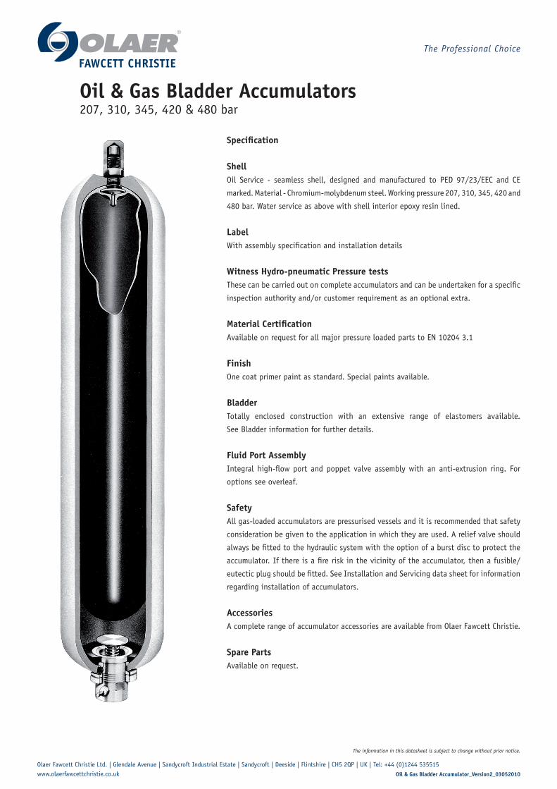
Oil & Gas Bladder Accumulators207, 310, 345, 420 & 480 bar
Specification
ShellOil Service - seamless shell, designed and manufactured to PED 97/23/EEC and CE
marked. Material - Chromium-molybdenum steel. Working pressure 207, 310, 345, 420 and
480 bar. Water service as above with shell interior epoxy resin lined.
LabelWith assembly specification and installation details
Witness Hydro-pneumatic Pressure testsThese can be carried out on complete accumulators and can be undertaken for a specific
inspection authority and/or customer requirement as an optional extra.
Material CertificationAvailable on request for all major pressure loaded parts to EN 10204 3.1
FinishOne coat primer paint as standard. Special paints available.
BladderTotally enclosed construction with an extensive range of elastomers available.
See Bladder information for further details.
Fluid Port AssemblyIntegral high-flow port and poppet valve assembly with an anti-extrusion ring. For
options see overleaf.
SafetyAll gas-loaded accumulators are pressurised vessels and it is recommended that safety
consideration be given to the application in which they are used. A relief valve should
always be fitted to the hydraulic system with the option of a burst disc to protect the
accumulator. If there is a fire risk in the vicinity of the accumulator, then a fusible/
eutectic plug should be fitted. See Installation and Servicing data sheet for information
regarding installation of accumulators.
AccessoriesA complete range of accumulator accessories are available from Olaer Fawcett Christie.
Spare PartsAvailable on request.
The information in this datasheet is subject to change without prior notice.

Olaer Fawcett Christie Ltd. | Glendale Avenue | Sandycroft Industrial Estate | Sandycroft | Deeside | Flintshire | CH5 2QP | UK | Tel: +44 (0)1244 535515 www.olaerfawcettchristie.co.uk
The Professional Choice
Oil & Gas Bladder Accumulator_Version2_03052010
FAWCETT CHRISTIE
A Bladder Kit comprising:
D Bladder assembly
D1 Bladder
D2 Gas valve assembly
D3 Locknut
D4 Protective cap
D5 'O' ring stem
E Anti extrusion ring assembly
E1 Anti extrusion ring
E2 'O' ring fluid port
E3 Bonded seal
E4 Back-up ring
B Fluid port assembly comprising
B1 Fluid port body
B2 Spring
B3 Poppet valve
B4 Collett
B5 Piston
B6 Flanged washer
B7 Locking ring
B8 Bleed adaptor
B9 Bleed valve
C Shell assembly comprising:
C1 Shell
C2 Label
C3 Label warning
See Port Option
HEAD DETAIL 04 TO 37L
GAS VALVE
STEM
(A/F)
(A/F)
J
K
H
FE G
P
D
A
B
C
Ø
Ø Note: Models 1/54 litres detailed above. Models
0.6 litres and below have Gas Valve assembly
integral with bladder stem without protective
cap fitted.
Nominal CapacityLitres
Effective Gas vol. Litres
Workpressure
bar
MaxFlow Rate
lt/min
WeightDryKilo
Dimensions in mm unless stated otherwise and subject to manufacturer's tolerances
AInches
BInches
C D E F G H K P
10 9.4 207 749 27.00 ¼ BSP ⅞ UNF 28 78 575 407 221 50 76 69
10 9.4 310 749 27.00 ¼ BSP ⅞ UNF 28 78 575 407 221 50 76 69
10 9.4 345 749 30.00 ¼ BSP ⅞ UNF 28 78 575 407 221 50 76 69
10 9.4 390/420 749 40.00 ¼ BSP ⅞ UNF 28 78 575 407 228 50 76 69
20 18.8 207 749 42.00 ¼ BSP ⅞ UNF 28 78 886 718 221 50 76 69
20 18.8 310 749 42.00 ¼ BSP ⅞ UNF 28 78 886 718 221 50 76 69
20 18.8 345 749 46.00 ¼ BSP ⅞ UNF 28 78 886 718 221 50 76 69
20 18.8 390/420 749 54.00 ¼ BSP ⅞ UNF 28 78 886 718 228 50 76 69
28 25.8 207 749 55.00 ¼ BSP ⅞ UNF 28 78 1158 990 221 50 76 69
28 25.8 310 749 55.00 ¼ BSP ⅞ UNF 28 78 1158 990 221 50 76 69
28 25.8 345 749 61.00 ¼ BSP ⅞ UNF 28 78 1158 990 221 50 76 69
28 25.8 390/420 749 70.00 ¼ BSP ⅞ UNF 28 78 1158 990 228 50 76 69
37 35.2 207 749 66.00 ¼ BSP ⅞ UNF 28 78 1407 1239 221 50 76 69
37 35.2 310 749 66.00 ¼ BSP ⅞ UNF 28 78 1407 1239 221 50 76 69
37 35.2 345 749 74.00 ¼ BSP ⅞ UNF 28 78 1407 1239 221 50 76 69
37 35.2 390/420 749 86.00 ¼ BSP ⅞ UNF 28 78 1407 1239 228 50 76 69
54 49.2 207 749 92.00 ¼ BSP M50x 1.5 69 66 1922 1766 221 50 76 69
54 49.2 310 749 92.00 ¼ BSP M50x 1.5 69 66 1922 1766 221 50 76 69
54 49.2 345 749 102.00 ¼ BSP M50x 1.5 69 66 1922 1766 221 50 76 69
54 49.2 390/420/480 749 119.00 ¼ BSP M50x 1.5 69 66 1922 1766 228 50 76 69
The information in this datasheet is subject to change without prior notice.

Olaer Fawcett Christie Ltd. | Glendale Avenue | Sandycroft Industrial Estate | Sandycroft | Deeside | Flintshire | CH5 2QP | UK | Tel: +44 (0)1244 535515 www.olaerfawcettchristie.co.uk
The Professional Choice
Oil & Gas Bladder Accumulator_Version2_03052010
FAWCETT CHRISTIE
54 - 0 - SA - CZ - 20 - 1 - Ex
Nominal Volume - Litres
Bladder Material
Oil & Gas Bladder AccumulatorsModel numbers
0 = Nitrile Standard2 = Low Temperature Nitrile3 = Low permeability Nitrile (23E-10cm³/s/cm/Hg) 6 = VitonK = Special low temperature Nitrile
Bladder Stem / Gas Valve
CZ = Unlined Shell, St.Steel Externals, 1/2” NPTF PortDL = Unlined Shell, St.Steel Externals, 1/2” BSPF PortDR = Unlined Shell, St.Steel Externals, 1/2” NPTF Double Seal Locking RingDU = Unlined Shell, St.Steel Externals, 1” NPTF PortDW = Unlined Shell, St.Steel Externals, 3/4” NPTF PortEZ = Unlined Shell, St.Steel Externals, 3/4 BSPF PortW6 = Unlined Shell, St.Steel Externals, 2” BSPF Port
Shell and Fluid Port options (J)
20 = 207 bar 31 = 310 bar34 = 345 bar 35 = 350 bar42 = 420 bar 48 = 480 barHigher pressure units available on request
Maximum Working Pressure
Design Standard/Authority Approval
Special Approvals
SA = 1/4” BSP Gas Valve, Stainless Steel Trim 3F = 1/4” BSP St. Steel Gas Valve, Stainless Steel Trim3L = As ‘SA’ but fitted with additional seals
1 = Lloyds/CE
Ex = ATEX Approval to 94/9/ECATEX - Accumulator conforms to ATEX DIRECTIVE 94/9/EC (non electrical equipment) Equipment Group II, category 2, atmosphere type GD. The equipment can be used in zone 1 & zone 2 above ground.
The information in this datasheet is subject to change without prior notice.