Fault-tolerant Control Motivation Definitions A general overview on the research area. Active Fault...
23
Fault-tolerant Control • Motivation • Definitions • A general overview on the research area. • Active Fault Tolerant Control (FTC) • FTC- Analysis and Development procedure • Supervisor architecture • Logic realization • Design and development tools • Implementation
-
Upload
rosaline-hensley -
Category
Documents
-
view
217 -
download
0
Transcript of Fault-tolerant Control Motivation Definitions A general overview on the research area. Active Fault...

Fault-tolerant Control
• Motivation
• Definitions
• A general overview on the research area.
• Active Fault Tolerant Control (FTC)
• FTC- Analysis and Development procedure
• Supervisor architecture
• Logic realization
• Design and development tools
• Implementation

Fault Tolerant Control• Motivation:
– Demand for higher autonomy and reliability requires considering all possible situations to guarantee correct and consistent operation
• Purpose:– Using a logically sound stepwise guideline to achieve
• Complete coverage of possible single faults.• Supportive software tools.• Avoiding unnecessary plant modelling.• Automatic code generation.
• Initial Prerequisites:– Initial system concept is established.– Systems requirements are specified: (operating modes and
functions, required performance, environmental, safety, or regularity requirements)

Approaches to achieve FTC
F au lt- to le ran t C o n tro l
P ass iv e A c tiv e
F D I o r S ID +reco n fig u ra tio n
R o b u stco n tro l
P ro jec tio n -b asedo r sw itch in g
o n -lin e red es ig no r ad ap tio n

FTC development procedure - I
ARRs
5
Structural analysis
Design
3
6
897
4
2
Effectordesign
Supervisordesign
Remedial action selection
Causal relation analysis
Severity assessment
Fault modelling
Fault propagation analysis
Detectordesign
Functionalstructuremodel
Componentfailuremodes
List ofpossible effects
FPAdata base
Desired effectsto be handled
Location forreconfiguration
Faults/effectsto be detected
Reconfigurationcondition
Commands andmonitoring
Remedialactions
1Analysis
Possible detectable faults+ sensor fusionpossibilities

FTC Development procedure - II

Fault Modelling

Failure Mode and Effect Analysis -FMEA
FMEA scheme for the Wheel system

FMEA – Other examples
FMEA scheme for the GPS

Fault assessment - I
• Severity Occurrence Index (SO)– Severity
Potential harm that fault effect inflicts the system; Severity is quantified by severity scale from 1 to 10.
– Occurrence; the frequency of fault occurrence during expected operational time interval; is quantified by by scale from 1 (unlikely to occure) to 10 (persistent failure)
– SO index:SO = Severity . Occurrence

Fault Assessment II
Severity and Occurrence analysis of the Wheel system

Fault Assessment III
Evaluation guidelines and identification of severe failures that need to be handled

Fault Assessment – List of faults
Periority assignment to different fault types

Fault Assessment – Causality Analysis
Identifying possible causes of failures by backwardsearch through the Wheel system

FMEA analysis and Structural Analysis
Components
Component'sabnormalfunction
Component'snormal
function
FMECA(Hazard analysis)
Structural analysis
Faults to behandled
MonitorableParts
Non-monitorable
Parts
Remedialaction selection
&
DetailedFDI design
Knowledge representation Knowledge formulation and manipulation
Abstraction Implementation & analysis Decision & design

Chosen approaches to detailed design (algorithms)
F au lt- to le ran t C o n tro l
P ass iv e A c tiv e
F D I o r S ID +reco n fig u ra tio n
R o b u stco n tro l
P ro jec tio n -b asedo r sw itch in g
o n -lin e red esig no r ad ap tio n

Supervisory Control - Definitions• To supervise:
To oversee and guide the work or activities of a group of people/system, etc.
• Supervision:– Monitoring a physical system and taking appropriate actions to
maintain the operation in the case of faults
– The ability to monitor whether control objectives are met. If not, obtain/calculate a revised control objective and a new control structure and parameters that make a faulty closed-loop system meet the new modified objectives. Supervision should take effect if faults occur and it is not possible to meet the original control objective within the fault-tolerant scheme.

Supervisor Architecture
S e t p o in ts
S en so rs
F ilte rin g &v a lid ity ch eck
C o n tro la lg o rith m s A c tu a to rs
E ffec to rs D e tec to rs
C on tro l leve l
S u p e rv iso r/d ec is io n lo g ic
In te rface
P lan t w id e co n tro l / o p e ra to r
D ata/ info.A ction
D ecision D etections
State info. & alarms
C ommand &set points

Logic realization•Language approach - a component based method•State-event machines
In fo rm a tio n acq u is itio n
In fo rm a tio n m an ip u la tio nan d d ec is io n ta k in g
P e rfo rm in g a c tio n
E v o lv in g /d e v e lo p in g
S en so rs
C o n tro lle rs
A c tu a to rs
(su b )system s
In t.co n d .
E x t.co n d .
E x t.co n d .
E x t.co n d .
E x t.co n d .
In t.co n d .
In t.co n d .
In t.co n d .
R espon sibility/ taskR edu n dan cy possibilities
H ard w arere d u n d an cy
H ard w are&
so ftw arere d u n d an cy
C on trol system s h ierarch y
Figure- Control system hierarchy consists of four principle components

Constructing the logic - Language approach
C o m p o n en tA
fA
O A
IA 3
IA 2
IA 1
IA 33
IA 32
IA 31
C o m p o n en tB
fB
O B
IB 1
IB 2
IB 3
IB 23
IB 22
IB 21
.
.
C o n tro lle r A c tu a to r P lan t
S en so r
C A P
S
O = H C .H C .H C .H C .
P P A C S
H C .H C .H C .H C . .................... = [H C .H C .H C .H C ]
P A C S
P A C S
(a ) w ith lo op
C o n tro lle r A c tu a to r P lan t
S en so r
C A P
S
O = H C .H C .H C .H C .P P A C S .
= [H C .H C .H C .H C ]P A C S
1
(b ) w ith o u t lo op
O P
O P
Fig.1
Fig.2
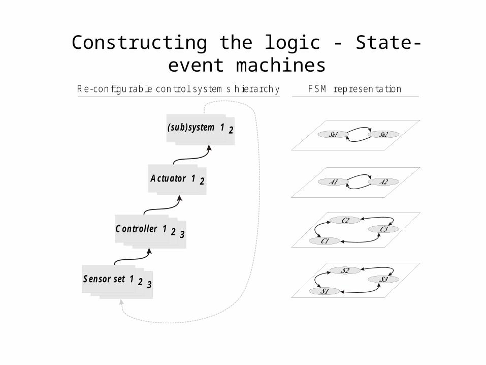
Constructing the logic - State-event machines
(su b )system 2
A ctu a to r 2
C on tro ller 3C on tro ller 2
S en sor se t 3S en sor se t 2
C on tro ller 1
A ctu a to r 1
R e-con figu rable con trol system s h ierarch y
S en sor se t 1
(su b )system 1
F S M represen tation
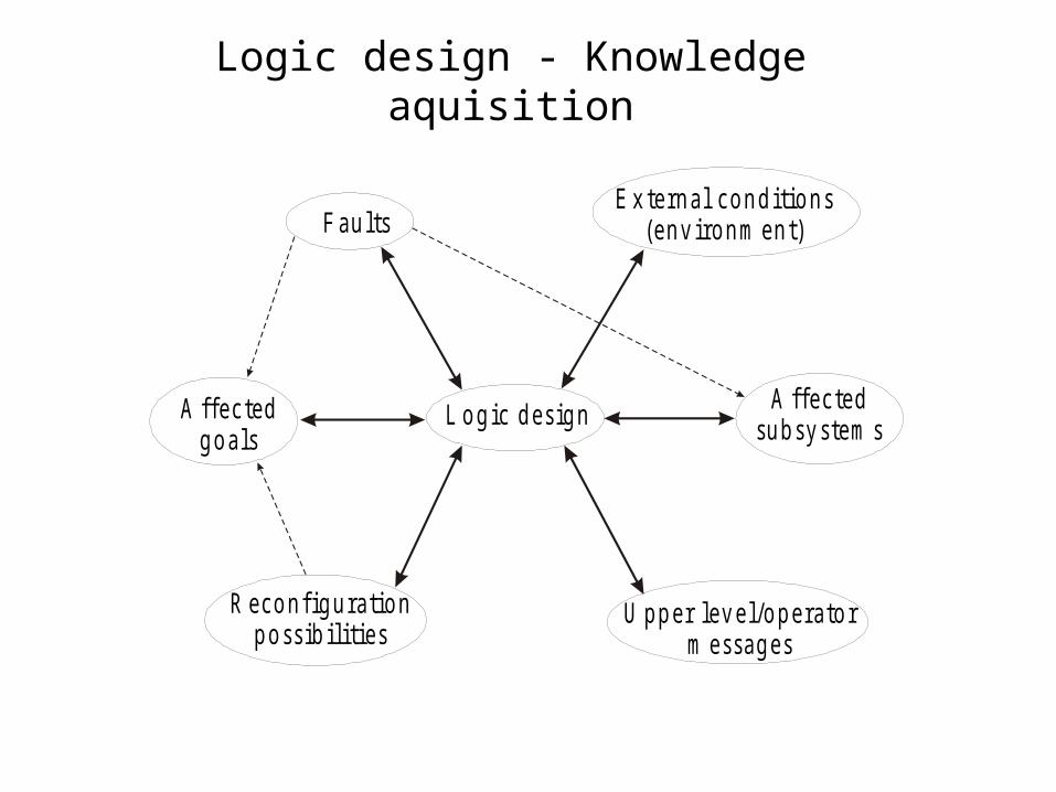
Logic design - Knowledge aquisition
L o g ic d es ig n
F au ltsE x te rn a l co n d itio n s
(en v iro n m en t)
A ffec tedsu b sy s tem s
A ffec tedg o a ls
R eco n fig u ra tio np o ss ib ilitie s
U p p e r lev e l/o p e ra to rm essag es

Design Tools and implementaion
• Tools– Statecharts
• Hierarchy/depth
• Concurrency
• Comunication
– Stateflow (Matlab)
– Beologic (B&O)
• Consistency/correctness– Beologic
• Implementation– IF-THEN rules
– Object Oriented structure

Exercise and next lecture • Exercise
• Objectives: » System analysis and knowledge acquisition about
faults and their effect on the system operation.
» Consider reconfiguration possibilities
• Next lecture• Structural analysis approach:
– Monitorable vs. non-monitoravble part of the systems