Fault Tolerance Techniques for Hybrid CMOS/Nano...
17
Fault Tolerance Techniques for Hybrid CMOS/Nano Architecture Aissa Melouki, Saket Srivastava and Bashir M. Al-Hashimi School of Electronics and Computer Science University of Southampton Southampton, SO17 1BJ, UK {am06r,ss3,bmah}@ecs.soton.ac.uk Abstract We propose two fault tolerance techniques for hybrid CMOS/nano architecture implementing logic functions as Look-Up Tables. We compare the efficiency of the proposed techniques with recently reported methods that use single coding schemes in tolerating high fault rates in nanoscale fabrics. Both proposed techniques are based on error correcting codes to tackle different fault rates. In the first technique, we implement a combined two dimensional coding scheme using Hamming and BCH codes to address fault rates greater than 5%. In the second technique, Hamming coding is complemented with Bad Line Exclusion technique to tolerate fault rates higher than the first proposed technique (up to 20%). We have also estimated the improvement that can be achieved in the circuit reliability in the presence of Don’t Care Conditions. The area, latency and energy costs of the proposed techniques were also estimated in the CMOS domain. I. I NTRODUCTION Molecular electronics holds the promise to overcome the physical limitation of lithography-based VLSI technology and offer the possibility of significantly denser circuits. However, tremendous growth in device density will be accompanied by a substantial increase in hard [1], [2], [3] and soft [4], [5], [6] faults. To achieve acceptable levels of manufacturing yield and computational reliability, fault tolerance must be integrated into the design flow of nanoscale circuits. Much work has already been done in the area of fault tolerance/avoidance for nanotechnology to increase circuit reliability in the presence of increased hard and soft error rates. One of the proposed techniques, Triple-Modular- Redundancy (TMR), is based on the use of three copies of the same module and an arbitration unit [7], [8]. TMR technique fails when there are faults in more than one module. The reliability of TMR is also limited by that of the final arbitration unit making this approach insufficient in the presence of high defect rates [7]. Reconfiguration is another technique that can circumvent physical defects by first mapping defects on reconfigurable fabrics then synthesising a feasible configuration to realise an application for each nanofabric instance [9], [10], [11]. However, defect mapping and reconfiguration is performed on a per chip basis which poses a scalability challenge. The
Transcript of Fault Tolerance Techniques for Hybrid CMOS/Nano...

Fault Tolerance Techniques for Hybrid
CMOS/Nano ArchitectureAissa Melouki, Saket Srivastava and Bashir M. Al-Hashimi
School of Electronics and Computer Science
University of Southampton
Southampton, SO17 1BJ, UK
{am06r,ss3,bmah}@ecs.soton.ac.uk
Abstract
We propose two fault tolerance techniques for hybrid CMOS/nano architecture implementing logic functions as
Look-Up Tables. We compare the efficiency of the proposed techniques with recently reported methods that use
single coding schemes in tolerating high fault rates in nanoscale fabrics. Both proposed techniques are based on error
correcting codes to tackle different fault rates. In the first technique,we implement a combined two dimensional coding
scheme using Hamming and BCH codes to address fault rates greater than 5%. In the second technique, Hamming
coding is complemented with Bad Line Exclusion technique to tolerate fault rates higher than the first proposed
technique (up to 20%). We have also estimated the improvement that can beachieved in the circuit reliability in
the presence of Don’t Care Conditions. The area, latency and energycosts of the proposed techniques were also
estimated in the CMOS domain.
I. I NTRODUCTION
Molecular electronics holds the promise to overcome the physical limitation of lithography-based VLSI technology
and offer the possibility of significantly denser circuits.However, tremendous growth in device density will be
accompanied by a substantial increase in hard [1], [2], [3] and soft [4], [5], [6] faults. To achieve acceptable levels
of manufacturing yield and computational reliability, fault tolerance must be integrated into the design flow of
nanoscale circuits.
Much work has already been done in the area of fault tolerance/avoidance for nanotechnology to increase circuit
reliability in the presence of increased hard and soft errorrates. One of the proposed techniques, Triple-Modular-
Redundancy (TMR), is based on the use of three copies of the same module and an arbitration unit [7], [8]. TMR
technique fails when there are faults in more than one module. The reliability of TMR is also limited by that of
the final arbitration unit making this approach insufficientin the presence of high defect rates [7]. Reconfiguration
is another technique that can circumvent physical defects by first mapping defects on reconfigurable fabrics then
synthesising a feasible configuration to realise an application for each nanofabric instance [9], [10], [11]. However,
defect mapping and reconfiguration is performed on a per chipbasis which poses a scalability challenge. The

2
prohibitively low reliability of these new nanodevices dictates that they must be interfaced with CMOS circuits to
tolerate the inevitable high fault rates. This leads to a newparadigm of hybrid CMOS/Nano architecture [12], [13],
[14], [15] to perform reliable computing using unreliable components (nanodevices). In this architecture, nanoscale
devices offer a highly dense fabric for data storage and computation, whereas CMOS components are utilised for
interfacing and for highly critical circuit operations. Both CMOS circuits and high fault rates will reduce the net
density delivered by these nanodevices.
Recently, Error Correcting Codes (ECC) have been proposed as a promising approach to improve the reliability
and yield of heterogeneous CMOS/nanodevices systems. In [12], [6], ECCs were mainly used for the suppression of
soft errors rather than physical defects i.e. maintaining the fault tolerance level rather than enhancing defect tolerance.
In [12], authors suggested a hybrid fault tolerance technique based on Hamming code and reconfiguration. In [6],
the authors proposed an implementation of ECCs based on the theory of Markov random fields (MRF) to combat
soft faults thus increasing the reliability of hybrid systems. In [13], two nanoelectronic memory fault-tolerant system
design approaches based on Bose-Chaudhuri-Hocquenghem (BCH) codes were suggested. Previously, single error
correcting codes such as Hamming and BCH have been used in thecontext of reliable memory designs [12], [16].
In [16], the authors explored combining error correction codes with various repair techniques to combat the high
defect rates in hybrid CMOS/Nano fabrics with particular focus on memory architectures. The previous works have
only addressed fault tolerance in memory architectures. ECC-based techniques can also be applied to memory-based
implementation of logic circuits (i.e. Look-up Tables) which includes Don’t Care Conditions (DCCs). The presence
of DCCs in Boolean logic functions presents a strong case to apply these techniques to circuits implemented as
Look-Up Tables (LUTs) on CMOS/nanodevice fabrics. As we will demonstrate in this work, the existence of DCCs
can be exploited in this type of architecture since it helps in masking of erroneous bits which is not possible in
memory design.
Fig. 1 gives an overview of the targeted hybrid CMOS/nano architecture. The proposed architecture is technology-
independent i.e. the nanoscale fabric is built using any of the recently proposed nanodevices including carbon nan-
otubes (CNT) or silicon nano-wires (NW). The techniques proposed in this work target CMOS/nano computational
architecture incorporating a LUT implementation of logic functions, as outlined in [17]. LUT implementation is an
effective functional-coding approach that provides low-level protection of individual Boolean functions [18], [19].
In our experiments, the LUTs under test are represented by randomly generated symmetric matrices of sizes ranging
from 23×3 to 26×6 where the probability of 0 and 1 are equal. The errors are injected randomly in the nanofabric
causing the corresponding bits to change their values (i.e.1→ 0 or 0→ 1). We have assumed random distribution
of errors to simulate the worst case scenario as correlated errors are technology specific. The proposed fault tolerant
techniques are based on ECC and partial redundancy to address the permanent and transient faults in nanoscale
LUTs. In the first technique, we implement a two dimensional coding scheme using Hamming and BCH codes to
address both hard and soft errors in the presence of high fault rates. In the second technique, we target the high
physical defect rates in the nanofabric by integrating ECCswith bad line exclusion technique. In this technique,
the high bit density offered by nanodevices is exploited to provide the necessary spare rows to compensate for
August 27, 2009 DRAFT

3
Fig. 1. Hybrid Nano/CMOS Architecture Overview
the defective lines. While the exact manufacturing defect rate and transient error rate are not yet pinpointed, it
is believed that they will easily exceed 10% [2]. The authorsin [17] assume small fault rates (less than 10%) in
nanofabrics for small LUT sizes with 50% of LUT entries set asDon’t Care Conditions (DCC). We first investigate
the effectiveness of our proposed techniques over the methods [17], [12] in high defect rate scenario.
II. PRIMITIVES
We first examine the ineffectiveness of using single ECCs such as Hamming and BCH in the presence of high
error rates for different LUT sizes.
A. Hamming
Hamming is a single-error-correcting and double-error-detecting code i.e. the code is capable of correcting one
error and detecting two errors in a codeword. A typical Hamming code is (2m−1, 2m−m−1), in other words, for
2m−m−1 data bits,m parity bits need to be added for full protection.
To demonstrate the reliability improvement that can be achieved from the techniques discussed in this work, we
have performed experiments on randomly-generated symmetric LUTs where the probability of 0 and 1 are equal.
The LUTs are of sizes ranging from 23×3 (3 inputs, 3 outputs) to 26×6 (6 inputs, 6 outputs). The circuit failure
probability Fm, resulting from randomly injectingm errors, is obtained by calculating the ratio of defective LUTs
after decoding to the total number simulation iterationsI = 5000. In this work, we assume that a nanodevice is
subject to both stuck-open and stuck-short defects with equal probabilities. We also assume that errors are uniformly
distributed across the fabric where both physical and transient errors are random and statistically independent. For
comparison purposes, we use the simple Hamming code [17] as areference point for the evaluation of our proposed
techniques.
Theoretically, the probability of a row of lengthl having m defective bits is given by the following binomial
equation:
P(m) =
(
lm
)
Pm(1−P)l−m (1)
August 27, 2009 DRAFT

4
0.0
0.1
0.2
0.3
0.4
0.5
0.6
0.7
0.8
0.9
1.0
Fai
lure
rate
0.0 0.05 0.1 0.15 0.2 0.25 0.3
Error rate
TheoreticalSimulation
24
4 LUT
Fig. 2. Hamming - Failure rate obtained through simulation and theory
0.0
0.1
0.2
0.3
0.4
0.5
0.6
0.7
0.8
0.9
1.0
Fai
lure
rate
0.0 0.05 0.1 0.15 0.2
Error rate
23
3 LUT2
44 LUT
26
6 LUT
Fig. 3. Hamming - Effect of varying LUT size on failure rate
whereP is the error rate of the fabric. The probability that the Hamming decoder fails to correctly decode an
erroneous codeword is equal to the probability of having more than one error per row. Using equation (1), this is
given by the following equation:
Prow =r+rpar
∑k=2
(
r + rpar
k
)
Pk(1−P)r+rpar−k (2)
where r and rpar are the number of bits and number of parity bits in a row respectively. The failure rate of a
LUT with c columns is equal to the probability that at least one row is defective and it can be computed as:
Pf ailure =c
∑k=1
(
ck
)
Pkrow(1−Prow)c−k (3)
In the case of 24×4 LUT, equations (2) and (3) can be rewritten as:
Prow =4+3
∑k=2
(
4+3k
)
Pk(1−P)4+3−k
Pf ailure =16
∑k=1
(
16k
)
Pkrow(1−Prow)16−k
Fig. 2 illustrates the failure rate obtained both theoretically (using equations 2 and 3) and through the above
simulation procedure. As can be seen, the two graphs are almost identical, validating the derived theoretical
equations.
Fig. 3 shows the variation of failure rate with respect to several percentages of injected error rates for different
LUT sizes. For defect rates as small as 1%, the Hamming code perfectly detects and corrects all faults for LUTs
of sizes smaller or equal to 24×4 as reported in [17]. However, it can be seen that even for a small LUT size of
August 27, 2009 DRAFT

5
1 1 0 1 0 0 0 1 0 1 1 0 0 0 1
Data bits Padded bits Parity bits
Fig. 4. BCH - Padding
23×3, and error rate greater than 5%, more than 10% of circuits fail. We can also observe that as the LUT size
increases, the fault tolerance of the circuit falls more rapidly indicating the inefficiency of this scheme.
B. Bose-Chaudhuri-Hocquenghem (BCH)
In this section, we examine fault tolerant approach using stronger BCH coding and evaluate its efficiency in
dealing with the high defect probabilities in nanoscale LUTs. BCH is a multilevel, variable length and easy to
decode ECC used to correct multiple random errors in a codeword. The simplest form of BCH codes is the single
error-correcting BCH(7,4,1) which is equivalent to Hamming code. We first examine BCH [13] with 0% Don’t Care
Conditions using BCH(15,7,2), which adds 8 parity bits in order to detect and correct 2 errors in the codeword.
The required word length is 7 bits; however the size of each entry in our LUT is only 4-bits in the case of 24×4
LUT. Therefore, we need to pad the data bits with the necessary bits so that it is equal to the required data word
size, as shown in Fig. 4.
The graph shown in Fig. 5 represents the failure rate achieved using the 2-bit error-correction BCH and in the
absence of DCCs. The fault tolerance obtained from the simulation results revealed a performance very similar to
Hamming. The reason behind this is that even though the BCH(15,7,2) code can tolerate more errors than single
error correction techniques, there is a higher probabilityof errors per codeword in LUTs. The padded bits and the
redundant bits added to the data word doubles the probability of faults in each entry of the LUT. The codeword is
15-bit long for the 2-bit error-correction BCH which is twice longer than the 7-bit long codeword for the single
error correcting Hamming code. Hence, strong ECCs have the capability of tolerating more errors at the cost of
more parity bits added to the codeword, which in turn makes them more vulnerable to higher fault rates; and hence
a rapid drop in their efficiency as the fault rate increases inthe LUTs.
Instead of coding row entries in LUTs, we use stronger ECCs such as BCH codes to encode columns. BCH(31,16,3)
for example can detect and correct 3 errors per column, but atthe cost of adding 15 parity bits. The results obtained
from simulations are shown in Fig. 5. For low error rates, BCHexhibits a better performance than Hamming. At
5% of errors, we can notice a 70% improvement in failure rate over Hamming. However, when errors exceed 10%,
this coding technique completely fails.
III. PROPOSEDFAULT TOLERANCE TECHNIQUES
In this section, we present two different hybrid fault tolerant techniques to address the high fault rates in nano-
LUTs. As we have seen earlier, single error correction schemes prove to be inefficient in dealing with such high
error rates. The first proposed approach combines Hamming and BCH to target higher error rates (greater than 5%),
while the second technique combines Hamming with Bad Line Exclusion to address error rates as high as 20%.
August 27, 2009 DRAFT

6
0.0
0.1
0.2
0.3
0.4
0.5
0.6
0.7
0.8
0.9
1.0
Fai
lure
rate
0.0 0.05 0.1 0.15 0.2
Error rate
Row Coding: Hamming(7,4,1)Padding: BCH(15,7,2)Column Coding: BCH(31,16,3)
24
4 LUT
Fig. 5. Failure rate comparison between different 1-D codingtechniques
A. Combined Two-Dimensional Coding : Technique 1
To reduce the failure rate for fault rates exceeding 5%, we implemented a two-dimensional coding technique
based on Hamming and BCH codes (also known asproduct code[20] [21]). The idea is to encode both rows and
columns in LUTs as shown in Fig.6(a). In [21], the authors proposed a Hamming-based two-dimensional coding
scheme to tolerate the occurance of random and burst errors in on-chip interconnects. The single error correction
Hamming code is used for both row and column encoding. In our proposed technique Hamming code is used to
encode data bits in each row of the LUT, and then a stronger BCHcode is used to encode each column. The
choice of BCH for column encoding is due to its ability to tolerate more errors in a codeword and given the size
of columns which is 2N, this choice seems appropriate. Retrieving data from the encoded LUT comprises of two
decoding steps. In the first step, columns are first decoded using the BCH decoder. This step will allow the detection
and correction of the biggest portion of errors because of the capability of the BCH decoder to correct more errors
in the codeword than the Hamming decoder. Then, in the seconddecoding step, the Hamming decoder is used to
remove the remaining faults.
We can further improve the fault tolerance of this techniqueby using systematic BCH code along withcheck bits
as illustrated in Fig.6(b). In systematic block codes, databits remain unchanged in the codeword, and the parity bits
are attached to the end of the data bit sequence. We exploit the fact that the number of 1’s in any wrong decoded
word will most probably be different from the number of 1’s inthe expected correct word. Therefore, we use check
bits to store the number of 1’s of each column after all row entries of LUT are encoded using Hamming. If the
number of faults per column exceeds the error correcting capability limit of Systematic BCH, the BCH decoder
will generate the wrong output and hence cause the entire technique to fail. Therefore, to avoid failure, the check
bits are always compared with the number of 1’s of the output of BCH decoder, if they are not equal, the codeword
August 27, 2009 DRAFT

7
Fig. 6. 2D Coding for 24×4 LUT (a) Hamming & BCH (b) Hamming & Systematic BCH with check bits.In the row encoding, Hamming(7,4,1)
is used to detect and correct one error per row by adding threeparity bits. BCH(31,16,3) is used to encode columns can detect and correct
three errors per column at a cost of adding 15 parity bits.
Fig. 7. Flow chart to illustrate the multiple-step decoding process of the proposed 2D coding technique
remains unchanged and all the faults in the first 16 bits of thecorresponding column are left to the second iteration
of decoding to be corrected using the Hamming decoder. The flow chart in Fig. 7 illustrates the decoding process
to retrieve rowM from a LUT of size 2N ×N.
Assuming the same error probabilityP for each bit, the probability of havingm defective bits in a column of
length (c+ cpar) follows the binomial distribution given in equation (1). Therefore, the probability that the BCH
decoder fails to correct a column because the number of faults exceeds its correction capabilitybch err is given
by:
August 27, 2009 DRAFT
8
0.0
0.1
0.2
0.3
0.4
0.5
0.6
0.7
0.8
0.9
1.0
Fai
lure
rate
0.0 0.05 0.1 0.15 0.2 0.25 0.3
Error rate
TheoreticalSimulation
24
4 LUT
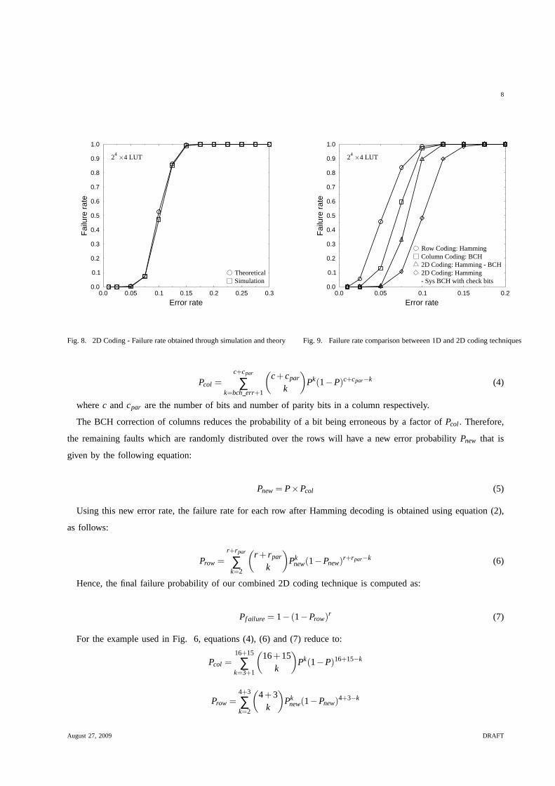
Fig. 8. 2D Coding - Failure rate obtained through simulation and theory
0.0
0.1
0.2
0.3
0.4
0.5
0.6
0.7
0.8
0.9
1.0
Fai
lure
rate
0.0 0.05 0.1 0.15 0.2
Error rate
Row Coding: HammingColumn Coding: BCH2D Coding: Hamming - BCH2D Coding: Hamming- Sys BCH with check bits
24
4 LUT
Fig. 9. Failure rate comparison betweeen 1D and 2D coding techniques
Pcol =c+cpar
∑k=bch err+1
(
c+cpar
k
)
Pk(1−P)c+cpar−k (4)
wherec andcpar are the number of bits and number of parity bits in a column respectively.
The BCH correction of columns reduces the probability of a bit being erroneous by a factor ofPcol. Therefore,
the remaining faults which are randomly distributed over the rows will have a new error probabilityPnew that is
given by the following equation:
Pnew= P×Pcol (5)
Using this new error rate, the failure rate for each row afterHamming decoding is obtained using equation (2),
as follows:
Prow =r+rpar
∑k=2
(
r + rpar
k
)
Pknew(1−Pnew)
r+rpar−k (6)
Hence, the final failure probability of our combined 2D coding technique is computed as:
Pf ailure = 1− (1−Prow)r (7)
For the example used in Fig. 6, equations (4), (6) and (7) reduce to:
Pcol =16+15
∑k=3+1
(
16+15k
)
Pk(1−P)16+15−k
Prow =4+3
∑k=2
(
4+3k
)
Pknew(1−Pnew)
4+3−k
August 27, 2009 DRAFT

9
Pf ailure = 1− (1−Prow)16
Fig. 8 shows the failure rate obtained both theoretically (Pf ailure) and through simulation in the case of 24×4
LUT. As we can see, there is an excellent correlation betweenexperimental and theoretical results.
The plots for simulation results of the circuit failure ratefor Hamming (7,4,1), BCH (31,16,3) and 2D coding
techniques are shown in Fig. 9. It can be seen that for error rates smaller than 15% 2D coding technique (without
check bits) exhibits better tolerance than both Hamming andBCH. For example, when the percentage of injected
faults is 5%, 2D coding perfectly detects and corrects all injected faults, whereas Hamming code achieves a failure
rate of approximately 45%. However, as the fault rate increases beyond 15%, this technique completely fails. This
improvement in reliability is achieved at the cost of a higher number of parity bits which will result in additional
area and energy overhead.
Fig. 9 also illustrates the enhancement achieved in fault tolerance by incorporating the check bits into the
technique. 2D coding with check bits achieves significantlylower failure rates for error rates greater than 5% and
upto 10% as compared to basic 2D coding technique resulting in an improvement of 37% in fault tolerance. As can
be seen, using check bits will improve the fault-tolerance of our combined 2D coding technique. However, the need
to store the number of 1’s in a highly-reliable memory (i.e. store at most approximately[log2(numrows)×numcolumns]
bits in a CMOS memory) will incur an extra area and delay overhead that need to be evaluated based on practical
IC designs as explained in Section IV.
Next we examine the effect of varying LUT size on circuit reliability. As can be seen in Fig. 10, the failure rate
increases rapidly for bigger LUTs. For a fault density of 10%, the failure probability to successfully instantiate a
LUT on the defective nanofabric increases from 5% in the caseof 23×3 LUT to complete failure for 26×6 LUT.
Comparing the results of Fig. 10 with Fig. 3, we can observe that combined 2D coding technique outperforms
single dimensional coding in terms of fault tolerance despite its insufficiency in coping with fault rates higher than
10% and bigger LUT sizes. In the case of 26×6 LUT, we can observe a nearly 0% failure rate at 5% error rate,
whereas Hamming completely fails.
Boolean functions are defined by their On-set, OFF-set and their DCC-set [17]. If an entry in a LUT is a
DCC, the output can be either 0 or 1. We examine the impact of DCCs on our 2D coding technique. In order to
theoretically calculate the circuit failure rate given thepercentage of DCCs in the LUT, we first need to calculate
the failure probability of the BCH decoder and the new error rate after decoding which are given by equations (4)
and (5). After column decoding, the probability that the Hamming decoder fails to correctly detect and correct all
errors does not only depend on the number of faults per each row, but also on the number of erroneous bits in
the output of the decoder. Therefore, the probability that agiven number of bits are erroneous in the output of the
decoder, denoted asP(n)bit , assuming a number of errors in the codeword has to be estimated wheren is smaller or
equal to the number of bits of the decoded word. For a 24×4 LUT, the values ofP(n)bit are shown in table I.
The failure rate of correctly decoding a row using the Hamming decoder is obtained using the following equation:
August 27, 2009 DRAFT

10
0.0
0.1
0.2
0.3
0.4
0.5
0.6
0.7
0.8
0.9
1.0
Fai
lure
rate
0.0 0.05 0.1 0.15 0.2 0.25
Error rate
23
3 LUT2
44 LUT
26
6 LUT
Fig. 10. 2D Coding - Effect of varying LUT size on failure rate
0.0
0.1
0.2
0.3
0.4
0.5
0.6
0.7
0.8
0.9
1.0
Fai
lure
rate
0.0 0.05 0.1 0.15 0.2 0.25 0.3
Error rate
TheoreticalSimulation
24
4 LUT50% DCCs
Fig. 11. 2D Coding - Failure rate obtained through theory and
simulation in the presence of 50% DCCs
P(n)bitnumber of errors in a codeword
2 3 4 5 6 7
P1bit 0.4306 0.1952 0.3639 0.1415 0 0
P2bit 0.4287 0.4274 0.4335 0.4271 0 0
P3bit 0.1407 0.3774 0.2026 0.4314 0 0
P4bit 0 0 0 0 1 1
TABLE I
HAMMING DECODER: DISTRIBUTION OF ERRONEOUS BITS IN THE OUTPUT WORD- 24×4 LUT
P′row =
r+rpar
∑k=2
[
(
r + rpar
k
)
Pknew(1−Pnew)
r+rpar−k×r
∑n=1
[
P(n)bit
n
∑m=1
(
nm
)
(1−PDCC)mPn−mDCC
]
]
(8)
The total failure probability is computed as:
Pf ailure = 1− (1−P′row)r (9)
Fig. 11 presents the failure rate obtained theoretically, based on the previously outlined equations, and using the
simulation procedure in the presence of 50% DCCs. The two graphs perfectly match each other which validates
our theoretical predictions.
Fig. 12 shows the results obtained before and after injecting 50% of Don’t Cares in 24×4 LUTs. As can be
observed, the optimum improvement is recorded at 10% error rate where the failure rate is reduced from nearly
50% to 37%.
August 27, 2009 DRAFT
11
0.0
0.1
0.2
0.3
0.4
0.5
0.6
0.7
0.8
0.9
1.0
Fai
lure
rate
0.0 0.05 0.1 0.15 0.2 0.25 0.3
Error rate
0% DCC50% DCC
24
4 LUT
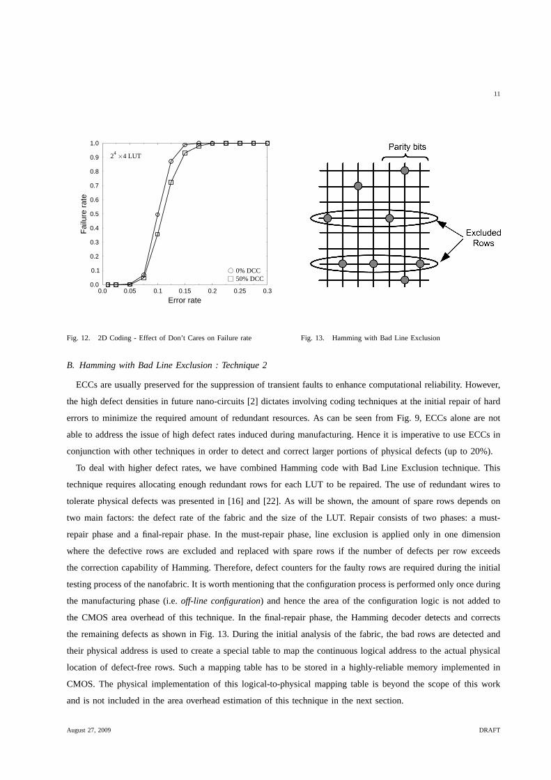
Fig. 12. 2D Coding - Effect of Don’t Cares on Failure rate Fig. 13. Hamming with Bad Line Exclusion
B. Hamming with Bad Line Exclusion : Technique 2
ECCs are usually preserved for the suppression of transientfaults to enhance computational reliability. However,
the high defect densities in future nano-circuits [2] dictates involving coding techniques at the initial repair of hard
errors to minimize the required amount of redundant resources. As can be seen from Fig. 9, ECCs alone are not
able to address the issue of high defect rates induced duringmanufacturing. Hence it is imperative to use ECCs in
conjunction with other techniques in order to detect and correct larger portions of physical defects (up to 20%).
To deal with higher defect rates, we have combined Hamming code with Bad Line Exclusion technique. This
technique requires allocating enough redundant rows for each LUT to be repaired. The use of redundant wires to
tolerate physical defects was presented in [16] and [22]. Aswill be shown, the amount of spare rows depends on
two main factors: the defect rate of the fabric and the size ofthe LUT. Repair consists of two phases: a must-
repair phase and a final-repair phase. In the must-repair phase, line exclusion is applied only in one dimension
where the defective rows are excluded and replaced with spare rows if the number of defects per row exceeds
the correction capability of Hamming. Therefore, defect counters for the faulty rows are required during the initial
testing process of the nanofabric. It is worth mentioning that the configuration process is performed only once during
the manufacturing phase (i.e.off-line configuration) and hence the area of the configuration logic is not added to
the CMOS area overhead of this technique. In the final-repairphase, the Hamming decoder detects and corrects
the remaining defects as shown in Fig. 13. During the initialanalysis of the fabric, the bad rows are detected and
their physical address is used to create a special table to map the continuous logical address to the actual physical
location of defect-free rows. Such a mapping table has to be stored in a highly-reliable memory implemented in
CMOS. The physical implementation of this logical-to-physical mapping table is beyond the scope of this work
and is not included in the area overhead estimation of this technique in the next section.
August 27, 2009 DRAFT

12
To obtain the probability of failure, we first calculate the probability Prow of a row of lengthl being excluded.
Prow is equal to the probability of having more than one bad bit in that row given by:
Prow =l
∑k=2
(
lk
)
Pk(1−P)l−k (10)
wherel is the number of bits in a row including the parity bits andP is defect probability of each bit. Therefore,
the probability of failure to instantiate a LUT on the fabricgiven the original number of rowsr and upper limit of
spare rowsrsp can be computed as:
Pf ailure =r+rsp
∑k=rsp+1
(
r + rsp
k
)
Pkrow(1−Prow)r+rsp−k (11)
In the case of 24×4 LUT and 25% spare rows, equations (8) and (9) can be rewritten as:
Prow =7
∑k=2
(
7k
)
Pk(1−P)7−k
Pf ailure =16+4
∑k=4+1
(
16+4k
)
Pkrow(1−Prow)16+4−k
Fig. 14 shows the failure rates for a 24×4 LUT for different error rates in the presence of various amounts of
spare rows. As can be seen, this technique is capable of tolerating an unprecedented percentage of defects when
compared to the Hamming alone and combined 2D coding technique shown in Fig 9. This is demonstrated by a
failure rate of nearly 0% for up to 20% of injected faults intorandomly generated 24×4 LUT.
To further our analysis, we examine the effect of variation in number of spare rows on the failure rate for different
LUT sizes. Fig. 15 demonstrates that as the error rate increases, more spares are needed to keep the level of fault
tolerance close to 0%. In the case of 24×4 LUT for instance, only 25% of spare rows are needed i.e. 4 more rows,
to completely tolerate up to 10% of faults rates. And as more errors are injected into the LUT, more spares should
be allocated and hence decreasing the useful bit density of the fabric. It can also be observed that as the LUT size
increases, the percentage of spares also increases to achieve low failure rates. For example, 26×6 LUT requires
twice its original size to tolerate 20% defect rate. However, we can minimize such high redundancy by adopting a
more powerful ECC such as BCH instead of Hamming.
While the authors in [17] assumed 50% don’t care conditions (DCC), our results have shown remarkable
improvement in fault tolerance even with zero percent DCCs in the LUT implementation. However, it can be
seen from Fig. 16 that the fault tolerance of this technique is significantly improved when we assume some of the
entries in the implementation as DCCs as compared to our results in Fig. 14.
The existence of DCCs (PDCC) in LUTs significantly reduce the bit failure rate as outlined in the following
equation:
P′ = P× (1−PDCC) (12)
August 27, 2009 DRAFT

13
0.0
0.1
0.2
0.3
0.4
0.5
0.6
0.7
0.8
0.9
1.0
Fai
lure
rate
0.0 0.05 0.1 0.15 0.2 0.25 0.3
Error rate
%Spares=25%%Spares=50%%Spares=75%%Spares=100%
Fig. 14. Hamming & Bad Line Exclusion - Failure rate obtained for
different percentages of spare rows-24×4 LUT
0.0
0.25
0.5
0.75
1.0
1.25
1.5
1.75
2.0
Per
cent
ageo
ofR
edun
danc
y/10
0
0.0 0.05 0.1 0.15 0.2
Error rate
23
3 LUT2
44 LUT
26
6 LUT
Fig. 15. Percentage of Redundancy needed to achieve 0% failure rate
for different LUT sizes
0.0
0.1
0.2
0.3
0.4
0.5
0.6
0.7
0.8
0.9
1.0
Fai
lure
rate
0.0 0.05 0.1 0.15 0.2 0.25 0.3 0.35 0.4 0.45 0.5
Error rate
0% DCC50% DCC
24
4 LUT50% Spares
Fig. 16. Hamming & Bad Line Exclusion - Variation of Failure rate
in the presence of Don’t Care entries. Inclusion of 50% DCCs improves
fault tolerance by almost two times.
0.0
0.1
0.2
0.3
0.4
0.5
0.6
0.7
0.8
0.9
1.0
Fai
lure
rate
0.0 0.05 0.1 0.15 0.2 0.25 0.3 0.35 0.4 0.45 0.5
Error rate
TheoreticalSimulation
24
4 LUT25% Spares50% DCCs
Fig. 17. Hamming & Bad Line Exclusion - Failure rate obtained through
theory and simulation in the presence of 25% spares and 50% DCCs
The new probability of a row being excluded after injecting Don’t Cares is obtained by replacing the fault rate
P with the new fault rateP′ in equation (8) as follows:
P′row =
l
∑k=2
(
lk
)
P′k(1−P′)l−k (13)
August 27, 2009 DRAFT

14
Fig. 17 illustrates the failure rate obtained both theoretically using equations 11 and 13 and through simulations.
As can be observed, there an identical match between the two graphs indicating the correctness of our derived
mathematical equations.
IV. I MPLEMENTATION
The realisation of fault tolerance in nano/CMOS nanoelectronic architecture will incur area, energy and operational
latency overhead in CMOS domain [15]. Such overhead must be taken into account when investigating and evaluating
hybrid CMOS/nanodevice fault tolerant architectures. Thehigh reliability decoders are implemented in CMOS and
therefore incur an increase in the area and energy consumption compared to the denser and low energy nano-LUTs.
Additional clock cycles are also lost in decoding and correcting codewords which cause latency overhead.
In order to obtain an estimate of the area, latency and energyoverheads per codeword, the corresponding decoders
were designed in VHDL and thoroughly tested through simulation using the appropriate test benches. Both Hamming
and BCH decoders are serial i.e. they receive 1-bit input andgenerate a 1-bit output per clock cycle, therefore, the
decoding latency is proportional to the codeword length. Using the 0.12µm CMOS standard cell library, the area
overhead of the Hamming decoder is 906µm2 and decoding one 7-bit long codeword requires 13 clock cycles and an
energy overhead of approximately 9pJ/MHz. The BCH decoder incurs higher overhead due to its high complexity:
an area overhead of 9132µm2, a latency of 69 clock cycles and an energy overhead of 286pJ/MHz. However, this
need to be further studied in the context of optimum design strategy where we negotiate the advantage of higher
density and low power dissipation against increased delay overhead.
The CMOS components as well as the redundant parity bits and spare rows in our techniques will reduce the
useful bit density offered by nanodevices. Therefore, another design parameter calledarea per useful bitratio is
used to compare the efficiency of the various techniques. Area per useful bit(a) reflects the area necessary to
achieve certain useful bit capacity and is obtained by dividing the total area of the fabric by the number of useful
bits in the LUT.
The total area of the fabric comprises of the area of nanodevices and that of CMOS subsystems. We adopt a
model presented in [14] to estimate the area of nanoscale memory. Each bank in the memory is composed of a set
of crossed nanoscale wires supported by a set of interface microscale wires. For a nano-circuit of 2n inputs andm
outputs, the area can be estimated as shown in [17]:
A =(
Wlith(n+ log2m)+Wnano2n).
(
Wlithn+mWnano2n) (14)
The main parameters in the model are the number of rows 2n and columnsm. The area of the nano-memory is
dominated by the address lines which are microwires.Wlith = 105nm is the wire pitch of the lithographic address
wires andWnano= 10nm is the pitch for the nanoscale wires. For instance, in the case of a 24×4 LUT, the area of
the nano-LUT before encoding is 0.84µm2.
Table II compares the area overhead of the proposed technique with the earlier approaches. While we have
seen that Hamming in combination with bad line exclusion achieves much better failure rates as compared to error
August 27, 2009 DRAFT

15
Technique Total Area
(µm2)
Area/Useful
bit (µm2/bit)
Hamming alone [17] 907 14
BCH alone [13] 9133 142
Hamming & Bad Line Excl.
(proposed)
908 14
TABLE II
AREA/USEFUL BIT OF THE PROPOSED TECHNIQUES
correcting schemes such as Hamming or BCH, this improvementin failure rate is achieved with little or no increase
in area overhead when compared with the simplest correctiontechnique proposed in [17]. It should be noted that
BCH has the highest area overhead due to the complexity of itsdecoding circuitry. Table II also shows the area
per useful bit ratio for a 24×4 LUT implemented using the three techniques.
While significant area improvement can be achieved over current CMOS for high density fabrics using hybrid
nano/CMOS architecture [13], it can be shown that further improvement in terms of useful bit density can be
achieved by sharing the decoders by multiple LUTs using timemultiplexing strategy as outlined in [17]. Another
way to minimise the CMOS area overhead is to synthesise logical circuits into smaller LUTs because the size of the
decoder increases proportionally with the size of the LUT. Moreover, as shown in the experimental results (Fig. 10
and Fig. 15), using smaller LUTs allows achieving higher levels of fault tolerance at the cost of low area overhead.
V. CONCLUSION
In this paper we investigated a promising look-up table based implementation of Boolean logic functions in
heterogeneous CMOS/nanodevice architectures. Our studies showed that single error correcting codes such as
Hamming or BCH prove their insufficiency in tolerating high error rates. We presented two hybrid fault-tolerance
techniques that address faults caused due to physical defects and transient faults. In the first technique, we encoded
both rows and columns of LUTs (using Hamming and BCH codes respectively) to target higher number of faults.
This technique significantly improves the fault tolerance with respect to single error correction schemes for error
rates greater than 5%. In the second technique, we complemented Hamming with bad line exclusion. This technique
results in remarkable improvement of failure rate against asubstantial fraction of bad nanodevices (up to 20%).
This is achieved at the cost of minimal increase in area overhead compared with Hamming, yet with much higher
efficiency in tolerating errors. Based on our studies this technique is very effective for LUT-based Boolean logic
architectures. We have also shown that the presence of don’tcare conditions in LUTs can significantly improve
circuit failure rates when we combine coding with bad line exclusion. Finally, we investigated the impact of these
techniques in terms of area, latency and energy overheads and showed that improved fault tolerance can be achieved
using the proposed techniques with little overheads compared to previous coding techniques.
August 27, 2009 DRAFT

16
VI. A CKNOWLEDGEMENT
The authors would like to acknowledge the EPSRC (UK) for funding this project in part under grant EP/E035965/1
as well as the Algerian Ministry of Higher Education and Scientific Research.
REFERENCES
[1] J. G. Brown and R. D. Blanton. A Built-in Self-test and Diagnosis Strategy for Chemically Assembled Electronic
Nanotechnology.J. Electron. Test., 23(2-3):131–144, 2007.[2] Z. Wang and K. Chakrabarty. Built-in Self-test and Defect Tolerance in Molecular Electronics-based Nanofabrics.J.
Electron. Test., 23(2-3):145–161, 2007.[3] R. I. Bahar. Trends and Future Directions in Nano Structure BasedComputing and Fabrication.International Conference
on Computer Design, 2006., pages 522–527, Oct. 2006.[4] M. Jacorne, C. He, G. de Veciana, and S. Bijansky. Defect tolerant probabilistic design paradigm for nanotechnologies.
DAC ’04. Proceedings. 41st, pages 596–601, 2004.[5] C. Zhao, S. Dey, and X. Bai. Soft-spot analysis: targeting compound noise effects in nanometer circuits.Design & Test of
Computers, IEEE, 22(4):362–375, July-Aug. 2005.[6] K. Nepal, R. I. Bahar, J. Mundy, W. Patterson, and A. Zaslavsky. MRF Reinforcer: A Probabilistic Element for Space
Redundancy in Nanoscale Circuits.Micro, IEEE, 26(5):19–27, Sept.-Oct. 2006.[7] K. Nikolic, A. Sadek, and M. Forshaw. Fault-tolerant techniques for nanocomputers.Nanotech., 13(3):357–362, 2002.[8] D. Thaker, R. Amirtharajah, F. Impens, I. Chuang, and F. Chong. Recursive TMR: scaling fault tolerance in the nanoscale
era. Design & Test of Computers, IEEE, 22(4):298–305, July-Aug. 2005.[9] M. Mishra and S. Goldstein. Defect tolerance at the end of the roadmap. In ITC, 1:1201–1210, 30-Oct. 2, 2003.
[10] C. He, M. Jacome, and G. de Veciana. A reconfiguration-baseddefect-tolerant design paradigm for nanotechnologies.
IEEE Design & Test, 22(4):316–326, July-Aug. 2005.[11] S. Copen Goldstein and M. Budiu. NanoFabrics: spatial computing using molecular electronics.IEEE ISCA, pages 178–189,
2001.[12] C. Jeffery, A. Basagalar, and R. Figueiredo. Dynamic sparingand error correction techniques for fault tolerance in nanoscale
memory structures.Nanotechnology, 2004. 4th IEEE Conference on, pages 168–170, Aug. 2004.[13] F. Sun and T. Zhang. Defect and Transient Fault-Tolerant System Design for Hybrid CMOS/Nanodevice Digital Memories.
Nanotech., 6(3):341–351, 2007.[14] A. DeHon, S. Goldstein, P. Kuekes, and P. Lincoln. Nonphotolithographic nanoscale memory density prospects.
Nanotechnology, IEEE Transactions on, 4(2):215–228, March 2005.[15] R. I. Bahar, D. Hammerstrom, J. Harlow, W. H. J. Jr., C. Lau,D. Marculescu, A. Orailoglu, and M. Pedram. Architectures
for Silicon Nanoelectronics and Beyond.Computer, 40(1):25–33, 2007.[16] D. B. Strukov and K. K. Likharev. Prospects for terabit-scale nanoelectronic memories.Nanotech., 16(1):137–148, 2005.[17] A. Singh, H. Zeineddine, A. Aziz, S. Vishwanath, and M. Orshansky. A heterogeneous CMOS-CNT architecture utilizing
novel coding of boolean functions.NANOARCH 07, pages 15–20, Oct. 2007.[18] N. R. Shanbhag, S. Mitra, G. de Veciana, M. Orshansky, R. Marculescu, J. Roychowdhury, D. Jones, and J. M. Rabaey.
The Search for Alternative Computational Paradigms.IEEE Design and Test of Computers, 25(4):334–343, 2008.[19] M. Ziegler and M. Stan. CMOS/nano co-design for crossbar-based molecular electronic systems.Nanotechnology, IEEE
Transactions on, 2(4):217–230, Dec. 2003.[20] T. Mizuochi, Y. Miyata, T. Kobayashi, K. Ouchi, K. Kuno, K. Kubo, K. Shimizu, H. Tagami, H. Yoshida, H. Fujita,
M. Akita, and K. Motoshima. Forward error correction based on block turbo code with 3-bit soft decision for 10-Gb/s
optical communication systems.Selected Topics in Quantum Electronics, IEEE Journal of, 10(2):376–386, March-April
2004.[21] B. Fu and P. Ampadu. An Energy-Efficient Multiwire Error Control Scheme for Reliable On-Chip Interconnects Using
Hamming Product Codes.VLSI Design, 2008:14, 2008.
August 27, 2009 DRAFT

17
[22] T. Lehtonen, P. Liljeberg, and J. Plosila. Online Reconfigurable Self-Timed Links for Fault Tolerant NoC.VLSI Design,
2007:13, 2007.
August 27, 2009 DRAFT