Fault Management Tools for a Cooperative
10
IEEE JOURNAL ON SELECTED AREAS IN COMMUNICATIONS, VOL. 12 , N O. 6, AUGUST 1994 I121 Fault Management Tools for a Cooperative and Decentralized Network Operations Environment Ewerton L. Madruga and Liane M . R . Tarouco A b s tr a ct - Some institutions do not have centralized computer network operations. In the case of UFRGS, some domains have their own group of people in charge of such a task locally and other domains do not. This work describes the university's net- work approach, as well as the fault management tools to sup- port such an approach. One of them, the CINEMA Alert Sys- tem, analyzes the network after polling entities and generates alerts when required. Another, the CINEMA Trouble Ticket System, helps the decentralized operations staff in cooperating during network failure recovery processes. The main features of the tools and software modules' organization to achieve a cooperative integrated network management environment are presented. I. INTRODUTION HE history of the UFRGS network is not different T rom many academic networks worldwide. Before a formal backbone was set, there were many LAN-based subnetworks spread in three campuses with individual connection to the national academic network each. Op- erations were done in each site in an independent fashion since each site had a local manager responsible for pro- viding the best possible service to department users. In the case of local major problems, informal discussion among managers and network experts used to take place most commonly by e-mail. After the UFRGS network backbone finally connected the previously established subnetworks, they became do- mains of well-defined scope. Fig. l illustrates the topol- ogy of the network. Nowadays, equipment ranges from small PC and RISC workstations to a supercomputer CRAY YMP/2E. So the network community soon real- ized the need for an operations center which had to sup- port such peculiar organization. To deal with this environment, a proposal for network management at UFRGS was designed. It is referred to as the Cooperative Integrated Network Management envi- ronment, a cooperative and integrated way to manage the TCP/IP UFRGS network. The university network com- munity believes that the approach is more responsive to user needs. This is because it proposes Help D esks closer to user sites and domain managers supporting all activi- ties. Once domain managers are more aware of the user Manuscript received July 19, 1991; revised July 24, 1991. E . L. Madruga is with the University of Caxias do SUI, Brazil. L. M . R. Tarouco is with the Computer Sciences Post Graduation Pro- gramme (CPGCC), Institute of Informatics (11). Federal University of Rio Cirande do SUI (UFRGS), P. Alegre, Brazil. IEEE Log Number 9401465. Processing "Central" Microwave ink Fig. 1. T he topology of UFRGS network. environment than in a centralized approach, it is expected that the problems will be solved faster. Among CINEM A network operations support tools, there is an application for trouble tracking that helps operators to cooperate with each other every time faults and problems appear. There is also an alert system that helps the operations staff to detect critical situations by monitoring specific indicators around the network. The alert system can create tickets automatically with the application programming interface provided by the trouble-tracking system. 1 1 . CINEMA-A COOPERATIVE NTEGRATED ETWORK MANAGEMENT NVIRONMENT As defined by [6] , he general goal of any Network Op- erations Center (NOC) is to provide a level of consistent network service to its user community. Furthermore, in the UFRGS case, the NOC has to cope with many estab- lished domains and problems coming from these domains, as well as from the backbone that connects them. It is important to notice that the network is continuously ex- panding, and not only will domains with well-structured management be added, but departments with user groups lacking such organization as well. Given the context, as suggested by [lo], faults are dis- patched to NOC and solved in three levels. First Level: Misunderstood procedure, user software or equipment setup parameters. Such a type of problem is isolated and repaired immediately. Sometimes, a visit to user is needed. Second Level: Problems concerning network com- ponents' failure in either hardware, software, or applica- tion. An externa l or university technician visit is probably required. Third Level: Multiple component's failures are, in general, intermittent and not easily isolated. Such prob- 0733-8716/94$04.00 0 994 IEEE
-
Upload
tiago-bertolini -
Category
Documents
-
view
215 -
download
0
Transcript of Fault Management Tools for a Cooperative

8/2/2019 Fault Management Tools for a Cooperative
http://slidepdf.com/reader/full/fault-management-tools-for-a-cooperative 1/10
IEEE JOURNAL ON SELECTED AREAS IN COMMUNICATIONS, V O L . 12 , N O. 6, AUGUST 1994 I121
Fault Management Tools for a Cooperative and
Decentralized Network Operations Environment
E w e r t o n L . M a d r u g a a n d L i a n e M . R . T arouco
Abstract-Some institutions do not have centralized computernetwork operations. In the case of UFRGS, some domains havetheir own group of people in charge of such a task locally andother domains do not. This work describes the university's net-work approach, as well as the fault management tools to sup-port such an approach. One of them, the CINEMA Alert Sys-tem, a nalyzes the network after polling entities and generatesalerts when required. Another, the CINEMA Trouble Ticket
System, helps the decentralized operations staff in cooperatingduring network failure recovery processes. The main featuresof the tools and software modules' organization to achieve acooperative integrated network management environment arepresented.
I . INT RODUT ION
HE history of the UFRGS network is not differentT rom many academic networks worldwide. Before aformal backbone was set, there were many LAN-basedsubnetworks spread in three campuses with individualconnection to the national academic network each. Op-erations w ere done in each site in an indep endent fashion
since each site had a local manager responsible for pro-viding the best possible service to department users. Inthe case of local major problems, informal discussionamong managers and network experts used to take placemost commonly by e-mail.
After the UFRGS network backbone finally connectedthe previously e stablished subnetworks, they became do -mains of well-defined scope. Fig. l illustrates the topol-
ogy of the network. Nowadays, equipment ranges fromsmall PC and RISC workstations to a supercomputerC R A Y Y M P / 2 E . So the network community soon real-
ized the need for an operations center which had to sup-port such peculiar organization.
To deal with this environment, a proposal for networkmanagement at UFR GS was designed. It is referred to asthe Cooperative Integrated Network Management envi-ronment, a cooperative and integrated way to manag e theTCP /IP UFRGS network. The universi ty network com-munity believes that the approach is more responsive touser needs. This is because it proposes Help D esks closerto user sites and domain managers supporting all activi-ties. Once domain managers are more aware of the user
Manuscript received July 19, 1991; revised July 24, 1991.E . L. Madruga is with the University of Caxias do SUI,Brazil.L . M . R . Tarouco is with the Computer Sciences Post Graduation Pro-
gramme (CPGCC), Institute of Informatics (11). Federal University of RioCirande do SUI(UFRGS) , P. Alegre, Brazil.
IEEE Log Number 9401465.
Processing
"Central"
Microwave ink
Fig. 1. T he topology of UFRGS network.
environmen t than in a centralized appro ach, it is expectedthat the problems will be solved faster. Among C IN EM A
network operations support tools, there is an applicationfor trouble tracking that helps operators to cooperate witheach other every time faults and problems appear. Thereis also an alert system that helps the operations staff todetect critical situations by monitoring specific indicatorsaround the network. The alert system can create ticketsautomatically with the application programming interfaceprovided by the trouble-tracking system .
11. CINEMA-A COOPERATIVENT E GRAT E DE T WORKM A N A G E M E N TN V I R O N M E N T
As defined by [6] , he general goal of any Network Op-erations Center (NOC ) is to provide a level of consistentnetwork service to its user community. Furthermore, in
the UFRGS case, the NOC has to cope with many estab-lished domains and problems coming fro m these domain s,as well as from the backbone that connects them. It isimportant to notice that the network is continuously ex-panding, and not only will domains with well-structuredmanagement be added, but departments with user groupslacking such organization as well.
Given the context, as suggested by [lo], faults are dis-patched to N OC and solved in three levels.
First Level: M isunderstood procedure, user softwareor equipment setup parameters. Such a type of problem is
isolated and repaired immediately. Sometimes, a visit touser is needed.
Second Level: Problems concerning network com-
ponents ' failure in either hardware, software, or applica-tion. A n externa l or university techni cian visit is probably
required.Third Level: Multiple component's failures are, in
general, intermittent and not easily isolated. Such prob-
0733-8716/94$04.00 0 994 IEEE

8/2/2019 Fault Management Tools for a Cooperative
http://slidepdf.com/reader/full/fault-management-tools-for-a-cooperative 2/10
1122
SingleTT
Base I
IEEE JOURNAL ON SELECTED AREA S IN COMMUN ICATION S, VOL. 12, N O . 6, AUG US T 1994
DomainManagers
I
HelpDesk
lems require specific m onitoring tools and experts in dataanalysis as well.
Aimed at facing problems on three levels, the networkoperations center is organized as illustrated in Fig. 2 .There are three Help Desks acting as first contact pointsfor user problems’ reports in each of the three campuses.They must solve first-level problem s, w hich are supposedto be 70-80% of problems observed. In this way, HelpDesk staff act as NOC front-end operators, repairing asmany first-level faults as possible closer to problemsources. A Help D esk is the main contact for departme ntswithout engineers or experts to b e responsible for a localorganized management function.
When a problem cannot be properly diagnosed at theHelp Desk level, information about it is registered andforwarded to Serv ice Control staff, domain manage rs, and/or experts . Here is when the cooperative approach takesplace. Messages warning NOC staff of a new problem tobe solved are generated. If the problem is really urgent,
the Help Desk calls the Service Control to report the sit-uation and request imm ediate help. Th e urgent problem isthen traced, optionally with the help of some of the do-main managers. All relevant intermediary conclusionsduring the tracing process ar e registered. If the problem
turns ou t to be at least of the second lev el, all information
about it is registered in a trouble datab ase.
Besides supe rvising their dom ain, people ch arged withthe same tasks as the ones performed by H elp Desks , D o-main Managers control network components and helpsolve problems of the second and third level using their
expertise for doing so. And when domain managers ,Service Control staff, and experts team up to help whoev eris in need of help, a “troubleshooting council” is formed,and therefore cooperative network management takesplace. At the present time, electronic mail is being usedas the instrument for the exchange of opinions. Each ofthe “council’s” mem bers has access to the ticket system
through a local client software module. This local moduleallows members to inspect notes on a ticket, tracing itshistory, and to contribute with more information. A do-main manager, for instance, can check equipment in hisscope which is not able to answer pollings (ping, SNMPGET operations, etc.) and update the ticket based on hisor her impress ions .
The other part of UFRGS NOC organization is theService Control. This is the NOC’s staff responsible in
Help HelpDesk Desk
coordinating operations activities. T he ticket priority pol-
icy choice, NOC service quality control, and n etwork per-formance analysis are among Service Control main du-
ties.
111. TH E CINEM A TROU BLE ICKET YSTEM
Given such distributed organization for network oper-
ations, it is impossible for people to keep track of prob-lems in the long run. A tool is required to help NOC mem -bers in this task. The so-called trouble ticket systemallows any NOC operator e i ther from the Help Desk, a
domain, or Service Control to pick up an opened ticket
and work on it . Since many common problems cannot besolved in few minutes, and perhaps the repairing processdepends on an expert or technician not available at themoment, notes on a ticket are made every time some im-portant event comes around to either inform the person
responsible for the ticket about the new status or support
later work on the ticket.There are many interesting trouble ticket systems which
contributed to the CINEMA approach. A major reference
in the subject is RFC 1297 [3]. Using his experience asmember of Merit NOC, Johnson specifies a “wish list”for such systems. This RF C lists all desirable features fora trouble ticket system, one of the most important in ourview being the need for integration with other tools. Th eCINEMA Trouble Ticket System supports integration
with other applications through an application program-ming interface to be used by other tools designers.
T he HDMS Sys tem [8] is a quite complete Help Desk
application which features an interesting Problem Man-agement subsystem. Its vendor database is certainly agood idea for trouble ticket systems like UFRGS CINE-
MA’s which intend to generate Mean-Time-Between-Fai lure (MTBF) and Mean-Time-to-Repair (MTTR) re-
ports . These indicators help the network operation center
to identify what to inspect and what to do in the presenceof repetitive problems. For instance, a lower MTBF in-dicator does not always mean that the vendor service ispoor. If the MTBF of certain equipment is less than the
one provided by its vendor, and an equipmen t of the sam emodel and vendor located in other parts of the networkhas better performance, then this equipment’s environ-
ment conditions should be checked. But associatingMTBFIMTTR to vendors is also a major point when thequality of techn ical support is to be assured.
NEARnet’s ticketing [4] as some important attributesin its ticket structure. The “close code” field, for in -
stance, is valuable for statistics on problems and associ-ated solving procedures. It is a code that defines the sort
of problem (bad network interface, software misconfigu-ration, etc .) concerning the ticket just closed . That codecan be used as a reference later when new tickets are cre-ated, and when a survey on NOC activities (“problemsfaced” X “their solutions”) is required.
Although both HDMS and NEARnet’s ticketing sys-
8/2/2019 Fault Management Tools for a Cooperative
http://slidepdf.com/reader/full/fault-management-tools-for-a-cooperative 3/10
M A D R U G A A N D T A R O U C O : F A U L T M A N A G E M E N T TOOLS FOR NETWORK OPERATIONS I I23
?-7etwork
.......................................... :...................................... :......................Graphicalser pqInterface
Fig. 3 . C I N E M A trouble tracking
tems have interesting functionalities, they only allow hu-
mans to interact with the system. If other network man-
agement applications are used to detect critical situations,they can not open tickets to start maintenance proceduresautomatically. In the case when other tools need infor-mation on previous problems in a given network domain,it will not be possible as well. Unlike these systems, theCINEM A Trouble Ticket Sys tem can be integra ted withother applications, through a well-defined applicationprogramming interface. At present times, it is integratedwith an Alert System, and both are part of the CINEMAenvironmen t as illustrated in Fig. 3 .
The Alert System keeps polling the network to find can-didate faults for problem tracking much like the networkmonitoring system in the University of Illinois at Urbana-Champaign [7]. Each time a threshold is exceeded and
connectivity problems or error conditions are found, analert may be created. At the current stage of the project,the system is just smart enough to avoid alert bursts . Toachieve that, the Alert System’s module responsible forthe generation of alerts uses a set of rules, information in
the trouble ticket base, and in the configuration base, asillustrated in Figs. 3 an d 4.
A . Alerts and Tickets
Whenev er trouble tracking is a conce rn, alerts and tick-ets are very cl ose conce pts. An alert is related to the searchfor problems and a ticket to the solving process. Depend-ing on the type of the emerging alert, a ticket should becreated o r not.
Alerts in the CINEMA Alert System are created onlywhen a repairing action is required. The system’s userinterface does not get event dumps, but instead only mes-sages when a relevant failure is around. To achieve thispurpose, the alert system collects data periodically for
later p rocessing.The tool is designed at a first step to be used centrally
at Service Control and at local management domains.Nevertheless, the alert system can be used with so me ad-justments as a remote monitor, servicing different man-
agement dom ains in a similar fashion as suggested by theRFC 1271 (RMON MIB) [12]. Some objects and moni-tored en tities are defined for each dom ain, and only crit-ical data are sent to a central monitoring station. A majorresult of the deployment of this strategy is a lower net-work m anagemen t traffic in the backbone.
A set of selected network co mponen ts, a set of selectedMIB object instances for each component as well as their
sampling intervals, and a sampling window are given tothe alert system to start monitoring the network. Basi-cally, the components being monitored are routers andsome file/mail servers. Common MIB objects monitoredare (considering RF C 1213 [ 5 ] )
sysUpTime
i f A d m i n S t a t u s an d i f O p e r S t a t u s
i f n E r r o r s and i f O u t E r r o r s
i f l n D i s c a r d s a nd i f O ut D i s c ar d s
i f l n U c a s t P k t s a nd i f O u t U c a s t P k t s
i f l n N U c a s t P k t s an d i f 0 u t N U c a s t -
P k t s
Once repetitive resets are always harmful for the net-
work and for the equipm ent itself, sysUpT i me should bemonitored. W hen this object’s value is found restarted toooften in time, the monitored equipm ent is probably being
reset due to m alfunctioning, and this should be inspected.The actual status of each interface of a netw ork entity
( i Op e r S t a t us) should match the status desired by the
network administrator ( i fAdm i nSt a t us). In the case ofany difference, i .e . , if a network interface is down whenit was not supposed to be, a failure has occurred. A pe-
riodic check of these objects can show this discrepancy.The monitoring of both input and output discards as
well as unicast and nonunicast packets can anticipatecongestion conditions. Unicast and nonunicast countershelp baselining traffic patterns and detecting broadcast
storms.The sampling window is the amount of time in which
the sampled values of an object instance are considered to
detect any abnorm alities. The window slides forward anddiscards the oldest sampled value when a new sampledvalue comes in. The new sampled value is compared tothresholds based on the average of the previous sampledvalues that lie in the window. If the lower or upper bound-aries are crossed, an event is generated and an alert mayfollow. Then the cy cle goes on. Som e important practicalaspects to consider about threshold calculation and sam -pling w indow sizing can be found in [7 ] and [ l ] .
The CIN EMA Alert Sys tem m odule’s organization wasdesigned using some ideas of the ALLINK OperationsCoordinator(A0C) data f low [ l 1 1 . In ALLINK, there arediffere nt stages where problem information passes throughsince the beginning, when a message comes from a sub-network handler, is filtered, becomes an event which isprocessed an d if needed b ecomes an a lert, and then is fi-
nally displayed on the user interface. The CINEMA’S

8/2/2019 Fault Management Tools for a Cooperative
http://slidepdf.com/reader/full/fault-management-tools-for-a-cooperative 4/10
1124 IEEE J O U R N A L ON SELECTED A R E A S IN C O M M U N I C A T I O N S , V O L . 12, NO . 6 , A U G U S T 1994
- roubleTicketSystem
Obs M = Event generated
(a ) (b)
F i g . 5 . The hysteresis mechanism to limit event bursts.WFig. 4. Alert sys tem da ta f low.
Alert System approach is simpler, although very similarin this sense, and is presented in Fig. 4 .
The sam pler module polls selected network elem ents in
a given period requesting values of a given set of MIBobject instances for each com ponent keeping track of theinstances’ values during a sampling window . T he data re-quested by the sampler are sent to the data analyzer mod-ule.
Each new sam pled value arriving at this new m odule iscompared to a lower (or “falling”) and to an upper (or“rising”) threshold. If any of these thresholds is crossed,an event may be generated. The way the rising and fallingthresholds are used to limit event generation is quite sim -ilar to the hysteresis mechanism defined by [12] for theRMO N M IB Alarm Group. T he difference lies in the sit-uations when a new event can be generated. In generalterms, W aldbusser [12] states that a new rising event (thesampled value is greater than o r equal to the rising thresh-
old) can only be generated if the last event that occurredwas a falling event (whose value is less than or equal tothe falling threshold), as F i g . 5 show s. The analogy holdsfor falling events. However, in our opinion, this mecha-nism should consider ano ther parameter.
The hysteresis mechanism is effective in avoiding burstsof events when sam pled values oscillate around the rising
threshold, for instance [Fig. 5( a)]. If rising crossings hap-pen sparsely in time and no falling events are generatedin th e meantime [Fig. 5(b)], we consider sparse risingevents should be registered. Th e mechanism is not flexi-ble for such situations. So the time between events of thesame type either in seconds or in sam pling cycles is also
considered by the data analyzer module of the CINEMAAlert System. Once expired this length of time, any eventis generated regardless of its type.
Both falling an d rising thresholds are computed by thesystem a s the average of the previous samp led values thatlie in the sampling window plus a factor times the stan-dard deviation:
RT = p + (a x a)
FT = p + ( 5 x a)
where
RT = rising thresholdFT = falling threshold
= rising factor
5 = falling factorp = mean of values in sampling windowa = standard deviation of values in sampling win-
d o w ,
In fact, there are two of these factors, each associatedwith the rising and the falling threshold. Th ese factors canbe used for fine-tuning: n etwork operators can broaden o rnarrow the num ber of network offenders to care about bysetting these thresholds. T he greater accuracy in chang ingenvironm ents with a permanent up-to-date network statusis a major advantage of automatic threshold computation.Furt herm ore, opera tions staff is free from the periodic taskof searching for “typical” days to get a network baseline.
The stream of events coming from the data analyzer ist h e input of the event processor module. Based on a setof rules, this module will correlate events with eventsthemselves, information in the configuration database,opened trouble tickets, and any available information baseto generate alerts when appropriate. Alerts are then dis-patched to the next mod ule and displayed on the manage-
ment workstation screen. Th ere are rules designed to out-put alerts only when an action must be taken. Examplesof these rules are shown in Section IV-B .
The event processor is the most important module in
the CINEM A Alert System since it is the one that decides
whether an even t should b e notified to the operator o r not.Therefore, it is the system part in which intelligence isplaced. At the present time, this module performs somecheckings on events searching for similar events already
registered (same IP number, same object instance, sameevent type), but it can grow towards an expert system infuture work.
The last Alert System mod ule in the sequence that be-
gins with data collection and ends with on-screen infor-mation to network operators is the Alert Display Con trol-ler. This module’s role is managing the output of alerts
inserting, deleting, and getting user acknowledgmentsfrom the network operator’s workstation interface.
If the sampler, data analyzer, and event processor mod-ules are kept remotely, the alert system can be used with
some adjustments as a remote monitor as previously men-tioned. In this way , parts of the network can be monitoredlocally, the major advantage being the sm aller overall net-work managem ent traffic. The network compo nents, sam-pling intervals, and the object instances to be mo nitored,as in the case of the Manager-to-Manager MIB’s [2] an d

8/2/2019 Fault Management Tools for a Cooperative
http://slidepdf.com/reader/full/fault-management-tools-for-a-cooperative 5/10
M A D R U G A A N D T A R O U C O : F A U L T M A N A G E M E N T T O O L S F O R N E T W O R K O P E R A T I O N S I125
RMO N M IB’s Alarm Group, could be se t by way of con-
trol table entries sent to the remote monitor through the
network.
B. The Ticket Structure
The main purpose of the UFRGS network concerningtrouble t racking is to minimize M TTR while support ing
the cooperative integrated network ma nagem ent. A s illus-trated in Fig. 2, there is a single-ticket database. Thismeans that Service Control staff, domain managers, and
Help Desk people perform updates , i . e . , open, make
notes, and close tickets, in a single space. With such in-tegration, either a global view of network faults (insideand outside domains) or a specific view (own scope offaults) is accessible for all NOC members. In this sense,a s ingle t rouble t icket sys tem al lows NOC members to
provide support to each other and to be aware of currentstatus of the whole network regardless of in which build-
ing or campus they work.There are so me special fields on which the trouble ticket
system co unts to support the cooperative manag ement. At
every ticket open, as F i g . 6 illustrates, there is a field fora brief description of what is being reported by the com-plainant, apart from the fields that identify a ticket (like
“Ticket id” and “Ticket Statu s”). T his field comp letionis menu-d riven, easing later queries and ticke t identifica-
tion since it provides predefined optio ns. With th ose pre-defined options, users can refer to tickets also using thesort of problem to which it is associated. The menu-dri-ven com pletion ticket fields at every ticket open a re avail-
able to get as much information as poss ible from the usercalling the op erations center. This set of fields is there to
help operators proceed with the standard proced ures everyHelp Desk system should support to listen to the user at
the very first contact. Menu-driven completion fieldscompose a fea ture of many Help D esk sys tems observed,where there are completion option s for most of the fields.Menu-driven fields are important to avoid major typingmistakes w henever au tomatic fill-up is not possible.
Since failure recovery usually depend s on the interven-tion of many people in a decentralized operations center,
there should be a staff mem ber responsible for superv isingthe recovery process. This is the one who should contact
technicians if a problem solution has been delayed, andcall maintenance over and over if needed no matter if heor she is currently the one working directly with the spe-
cific ticket. Therefore, a field “Ticket Responsible” isused for this purpose. Th e ticket responsible could be as-
sumed as the opera tor who has opened the t icket . W hen-ever ticket responsibility changes, the new responsible
staff member gets a notification.The staff member working on the ticket is not always
the one responsible for the ticket. After the ticket isopened, a visit to the user might be required , for instance.In this sense, there should be a way to assign a problemto someone who is in a better position to help. The field
“Ticket Dispatched to” is used for this purpose at every
r9Opsn TIcket
TlcLat Status:~ p l nTlclgt I d
o p e n Date: 07/10193 Open Time: 0457pm Opened by:Ltontact: Extension: 6161
Workstation: coruja E-mail: rnaujosalnf Domain: inf.uhqr
Re r r ons l b l e : m n s l o n : 4 1 2 3 E-mall: lkcdnOc
Noti f icat ions: liane. mumu
Brie f Description:- TW hlgh rerponre t i m h
( S a v e ) - (ISIUQ)
%
Fig. 6 . Information for every ticket open.
ticket note. As soon as the ticket is dispatched to some-
one, a notification is made to this staff mem ber.At every note made on the ticket, an important event
has occurred. If the operator or technician working on theticket has not finished his task yet, the re are things left tobe don e. In this case, a special field can be used to remindthe staff memb er of the action to be taken at the right time.
Th e field “Nex t A ction” is used for that. A time and atext stating the step to be taken in the near future are as-sociated with the action . T he trouble ticket escalation pro-
cess presented in the next section keeps track of this field
for all opened tickets, and notifies the N OC staff memberscurrently working on them when it is asked to.
As stated before, another concern of t he CINE MA
Trouble Tick et System is controlling the quality of eq uip-ment and vendor support . Two of the commonly usedfields among many ticket-tracking systems can serve thispurpose . They are the t icket open and c lose t ime w hichbelong to the ticket record structure. The difference be-tween the open and close time of a ticket is used to cal-
cula te the Mean-Time-to-Repair for a network compo-nent, and the time difference between the previous close
and the next open time is used to calculate the Mean-Tim e-Between-Fai lures. Once MTT R and M TBF are avai lable,
reports can be g enerated correlating these data with man-
ufacturerhendor data fe tched from the NOC’s configu-ration database.
C . A Case Study
For a bet ter comprehens ion of the CINEMA troubleticket system ’s functionality, let us take a look at a typical
case in which the sys tem would be used. An end user from
the Biotechnology Center calls the Help Desk located incampus “V ale .” He has fe l t a sudden increase in re-sponse time on his local network. Th e Help Desk opera torhears the user and takes note of the user’s information:name, e-mail , phone extens ion, and the machine wherehe is currently logg ed in. B ased on the latter, the ticketingsystem automatically fetches configuration data, such as
domain and IP address . Then the opera tor fol lows a s tan-dard procedure , exchanging with the user as much infor-mation as possible, trying to solve the problem as a first-
level one. Since none of the first tests proved successfulto help diagnose the fault, the operato r can decide to open
a ticket. Some fields are automatically filled up: the re-sponsibility for the ticket is given to the operator openin g

8/2/2019 Fault Management Tools for a Cooperative
http://slidepdf.com/reader/full/fault-management-tools-for-a-cooperative 6/10
1136 I E E E J O U R N A L O N S E L E C T E D A R E A S I N C O M M U N I C A T I O N S , VOL. 12 , N O . 6. A U G U S T 1994
it , and the field “dispatched to” is given to the campustechnician encharged with the domain ‘‘Biotechnology
Center.” As soon as the ticket is saved, the technician isnotified by e-mail, and when his shift starts, the ticket isthen picked up.
Investigation begins by collecting data into the user’sdomain. Using monitoring tools, the technician observestoo high collision rates in network interfaces around thebiotechnology domain. Since he is not acquainted withsuch a type of situation, the technician issues a note onthe ticket with a help request to NOC engineers and ex-perts . Som e of the replies advised a gradual deactivationof workstations. While deactivating one workstation at atime, the technician found a proba ble faulty interface sincethe collision rate stopped increasing. This faulty interfaceis sent to Service Control, from where it will be sent torepair. A new note on the ticket is issued explaining theisolating procedure. T he “Ne xt Action” field is set to 24
hr later when the technician is supposed to test the faultyworkstation with a spare network card . Once the interfacewas replaced and the workstation reactivated, everythingseemed to be okay. A new note on the ticket is issued,
explaining the new domain status and dispatching it to theformer operator working on the ticket. Only after the
complainant’s acknowledgment can the ticket be closed.A close code identifying a class of problems related tonetwork interfaces is set, and a reference to the replacednetwork interface manufacturer is made. Whenever newproblems related to collisions appear, this ticket’s solu-tion procedure can be consulted and used as a guidelinefor troubleshooting.
L ) . System Modules Organization
The CINEM A Trouble Ticket Sys tem is based on theclient/server model, as shown in Fig. 7. Th e ticket serveris composed of five main modules: a console, the “w atch-dog ,” the kernel, database, and notification interfaces. Its
clients are any other applications that happen to be joiningthe CINEM A environm ent, as the alert system itself. It isimportant to note that the Trouble Ticket User Interfaceis also a client in the ticket system’s approach since it issupposed to run in work stations all around the university.
Due to its very nature, an NOC is there to keep trackof problems. The bigger the network, the more problemsthe operations center is supposed to handle simultane-
ously. So recovering failures as soon as possible is veryimportant to NOC and its image. The “watc hdog” is themodule responsible for helping network operators not toslow down and to keep productivity in reasonable termswhenever time is a critical factor. It schedules all “Nex tAction” ticket field values and notifies who is supposedto be notified in the proper time. T he “watchd og” mod-ule is also responsible for warning the trouble ticket sys-tem administrator (or somebody else if specified) whenthere are tickets neglected for a certain am ount of hoursor days, and when there are tickets opened for more thana certain am ount of hours or da ys. In the latter case, tick-
ets have their priorities optionally increased. If a ticket
K E R N E L
Server System
Fig . 7. A clientisewer approach for trouble tracking
dispatched to a technician, for instance, remains forgottenfor more than one day (because there have been no morenotes on it s ince then), t h e Service Control supervisorshould call him to check what is happening. The super-visor should b e notified about tickets opened for a consid-
erably long time (in NOC’s point of view), when theworkload will be evaluated, and possibly new staff thatcould be hired.
There are many p arameters to be set which will reflectin the services provided by the problem-tracking system .Furthermore, as in the case of other database systems,
there is a need for somebody who must administrate theapplication. That is what the Console module is for.
Security should be o ne of the system’s concerns. U singthe console , the adm inistrato r registers all people who willbe able to work on opening, issuing a note, or closing aticket: Help Desk and service control operators, servicecontrol supervisor, technicians, domain managers, andeventual NOC collaborators. Further details on each of
these classes of the operations staff are also set using theconsole, such as associating technicians to domains.
A s mentioned above, so me important parameters eitheraffect global service or should be kept homogeneous for
all ticket system clients. Theref ore, they must be han dledcentrally, and then are set by using the console module.The number of priorities supported is an example. Theconsole can also be used to specify the escalation time toeach priority, i .e. , the period after which the administra-tor gets notified by the module “watch dog” about ne-
glected tickets.The trouble ticket server’s main module is the “Ker-
nel. ” That is the module which carries out all the servicesrequested by CINEMA environment applications. All
“op en,” and “close” transactions-related requests com-ing from the network are serviced by the kernel based onthe parameter setup made at configuration time.
The database and notification interfaces provide sup-port to the kernel services. Th eir main purpose is shield-ing the kernel from the technology details used for infor-mation storage and delivery. The database interfaceimplements the functions required for a specific system,either a conventional relational or a distributed databasesystem, comm ercial or not. In the kernel’s point of view,it does not matter which on e is the database system in use.

8/2/2019 Fault Management Tools for a Cooperative
http://slidepdf.com/reader/full/fault-management-tools-for-a-cooperative 7/10
MADRUGA A ND TAROUCO: FAULT MANAG EMEN T TOOLS FOR NETWORK OPERATIONS 1 I2 7
This is also the case for the notification subsystem. Inthe presence of limitations or problems, this module mustchoose which is the channel to be used. Fo r instance, if atechnician is not reachable by e-mail, the notificationmodule either switches automatically to fax (and sendsmessages to the site closest to the technician) or sendsmessages to somebody else who is supposed to find thetechnician.
IV . IMPL E ME NT AT IONSPECTS
The prototypes of the CIN EM A environment tools pre-sented in this paper are being developed under a UNIX
platform. Th e CIN EM A alert and t icket appl ica t ions useSunNet Manager package API (Sun Microsystems Inc .)
as a development platform. A configuration database isset using this package’s console, and is accessed by bothCIN EMA applications. This console is also used by NO Coperators for eventual data and event requests, and whennetwork topology is to be consulted.
SunNet Manager’s API is used by the alert system tocollect data around the network before inform ation anal-ysis is performed. The API’s model based on the remoteprocedure call provides a comfortable environment forapplication designers. B esides the regular data for moni-toring (object instances, mon itored entities, polling inter-
vals, etc.), the alert system provides a callback functionto the API. T his function is run every time polled data, atrap, or a polling error arrives. Th e model is comfortablebecause the application needs neither to d o the actual poll-ing nor keep track of intervals between pollings. All thatis required is the function to handle data coming in at theintervals provided at the start.
The alert system’s sampler modu le is the one that sup-plies the monitoring data to SunNet Manager, and the data
analyzer module is exactly the callback function pro-vided. For every object instance coming to the callback
function, the sampled value and its associated arrivaltimestamp are stored in a local disk file. But before that,the workstation running the alert system, and thereforerunning the callback function, w ill compare the incoming
value to the thresholds for that specific objec t instance andgenerate an event if needed. Incoming t raps becomeevents automatically, without any processing by the dataanalyzer module.
A major limitation of the current version of SunNetManager is the lack of the possibility of sharing its run-time configuration database among NOC operators. Dueto this fact, this database must be replicated through dif-ferent sites. The natural implication of this approach is
that any change in the network configuration (new net-v. ork nodes, links deactivation, router operating systemupdate, etc.) must be reflected in the various databasecopies. At the present time, the NOC Service Control co-ordinates this update process. In the case of any chan ges,the local domain manager must inform the Service Con-
trol that is charged with informing all other domain m an-agers and Help Desks about the new network status. If,
in the future, a new version of the commercial package
used supports a distributed configuration database, the do -main managers are the ones who will update their do-mains’ local inform ation.
The SunNet Manager package provides an interestingplatform for application development, but has some pointsthat could be improv ed upon. Its API allow s applications
to have partial control of what is to be displayed onSunNet’s console. A pplications can create icons for mon-itored entities (h osts, routers, bridges, workstations, links,
etc.), connect them in logical views of the network, andsearch for them later. This feature provides an alternativeway to check the network topology. Unfortunately, it is
not possible to change the sta tus of objec ts in the cons ole,that is , if the cu stomized user application detects a criticalsituation in a managed en tity, there is no way to make theentity’s icon blink. Icons blink only when data are re-quested from the SunN et’s console.
Some of the package’s drawbacks can be addressedby the customized applications. The managementinformation base available in the managed entitiesprovides raw information through the object instances.
One interesting way of adding value to the obtainable in-formation is creating expressions from object instances.
Cons idering RFC 1213 [ 5 ] , if the operator reads thepercentage of inpu t errors in a given interface in the ex-pression i f I n E r r o r s / ( i I nUc as t P k t s +i f I nNU- c a s t Pk s ) , t will probably be more meaning-ful than just polling the number of input errors, i .e. ,i f I nE r r o r s . Expressions are not supported by SunNet
Manager, but they are supported by the CINEMA AlertSystem. Ano ther interesting feature not supported by thispackage but supported by the Alert System is automaticthreshold computation. Without it , the operations centerneeds to periodically compute thresholds to reflect thecurrent network status.
CINEM A’S tools use a windowing g raphical user in-
terface to gain flexibility (Fig. 8). The “cut and pas te”feature can be used, for example, to store into a ticketfield a mail message reporting pro blems. An alert can bedragged from the Alert System window an d dropped ontothe ticketing window to open a ticket whenever needed.To take advantag e of those attractive features, the proto-types are being developed using the XView program minginterface (Sun Microsystems Inc.).
A . Application Programming Interfaces
Care has been taken in designing an Application Pro-gramming Interface (API) for the trouble ticket system(Table I). The ticket’s API has four classes of primitives,allowing other CINEMA applications to retrieve and up-
date the trouble tickets’ data. T he programm ing interfaceis connection-oriented and mapped to UNIX socket sys-tem calls . When the client wants to retrieve tickets,
for instance it should establish a session with the ticketserver using CineTT- E s t ab l i s h ( ) , and useth e C i n e T T - G e t F i r s t T k t ( ) an d CineTT-Get-

8/2/2019 Fault Management Tools for a Cooperative
http://slidepdf.com/reader/full/fault-management-tools-for-a-cooperative 8/10
1128 IEEE JO U R N A L ON SELECTED A R E A S IN COMMUNICATIONS, VOL. 12 , NO. 6, A U G U S T 1994
Class P r i m i t i v e
Input CineSA-GetNextEvent 0
O u t u u t C i n e S A P u t A l e r t 0
CINEMA Trouble Ticket System v1.0
(Open) (Note) (close)query)(m)kt Sewer:.
Close Ticknt
1801 Ticknt i d 1801
Close Date: 08/13/93
Close Code: (Opt10ns) Bad NetWwk inferface
Component: minuano-ne1000
Solution Description
close The : 01:05prn
D e s c r i p t i o n
reads a new event
outp ut s an a l e r t t o be d i sp layed
Fig. 8. Trouble t icket system user interface.
Ticket
R e a d
Error SuDDort
TABLE I
C I N E M A T R O U B L EICKET P1 FOR C L I E N T S
Class j P r i m i t i v e I D e s c r i p t i o n
Ticket
C i n e T T D e l e t e T k t0C i n e T T .Ge t F i r s t T k t 0
CineTT-GetNextTkt 0
C i n e T T E r r o r O
delete a given t icket from DBfetches the first t icket of a given query
fetches next t icket in cur rent query
Drovides a strine eiven an error code
N e x t T k t ( ) to obtain the information required. When
ready, the client uses the C i neTT-Te rrn i n a t e ( ) to re-lease the session. A connection-oriented model was cho-
sen to provide a reliable communication between server
and clients located all around the university. Further-more, this model can be used to “bootstrap” parameterson the client side that should b e kept homogeneo us amon gall clients. That is the mechanism used, for instance, toinform the ticket system’s user interfaces around the uni-
versity of what are the priority levels with which the sys-tem currently works, and what are the escalation levelsassigned to each priority level.
To service the clients using the API above, the ticketserver does not require many features from the databasesystem used to store all tickets’ informations. A ll a data-
base system needs to offer for the ticket server is a C lan-guage programming interface with basic database primi-tives that support, including updating, indexing,retrieving, and excluding records. Reliability mecha-nisms, such as atomic transactions and use of check-
points, are also desirable. POSTGRES [9] is the databasesystem used curre ntly. It is a public domain softw are thatfulfills these requirem ents and has so me interesting extrafeatures. The most relevant POSTGRES’ feature in CIN-EMA Trouble Ticket System’s point of view is the pos-sibility of customization. The user can implement querylanguage operators using C language and bind them toPOSTGR ES. W e expect to use this fea ture to implementa full-record scan, that is , the search for records is based
on a given regular expression compared to every field of
TABLE 11
C I N E M A A L E R T Y S T E M ’ SV E N T R O C E S S O RR O G R A M M I N GN T E R F A C E
] C i n e S A A c k A l e r t0 I acknowledges an old alert
every ticket. It means, for example, that ticket system
users can search for all tickets that refer to a word sim ilarto “m odem ” in any of the ticket fields.Table I1 shows the primitives provided for the Alert
Sys tem’s Event Processor module development . Al-though small in number, the programming interface has
its flexibility increased by the API’s provided by otherCINEM A appl icat ions , l ike the t rouble t icket sys tem. Re-call that this is the mo dule where filtering is performed .
B. Filtering
The incoming events read with the input primitive inTable I1 are subm itted to a set of rules fo r alert generation.These rules are built based on the practical ex perience ofthe university’s engineers. The filtering process may re-sult in discarding some incoming events, increasing
counters for others, and generating alerts based just onone or a set of events that really dema nds it . It should benoted that it is up to the Event Processor m odule designersto create their own strategies to handle the eve nts. It means
that all other modules are stable, but the event processormodule is the only on e that keeps being customized pro-gressively. Currently, this module keeps an event history
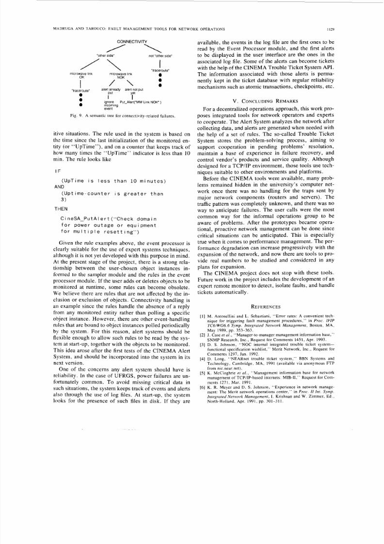
table to perform simple event correlation for alert gener-ation. This correlation and general conditions are set onan i f . . . t h e n . . . e I se . . . basis. At thepresent time, for instance, one of the Event Processor’sconcerns is related to connectivity problems that arisewhen a microwave link which connects one of the cam-puses to the rest of the university’s network goes down.Whe n there is an event indicating that the link went down ,
all other later events related to hosts and network com-ponents located on the “other side” of the link are ig-
nored. T he sem antic tree is illustrated by F i g . 9.
The semantic tree in F i g . 9 is described by the rule
o b le m i s c o n n e c t i v i t y ) AND
oblern i s c o n n e c t i v i t y w i t h
her s id e” ) AND
c r owav e l i n k i s down) AND
e r t n o t g e n er a t ed y e t )
C i neSA-PutA I e r t (“mi c rowave
l i n k i s d o wn !” )
Another concern is multiple resets and power outages.Multiple resets indicate bad behavior in routers, for in-stance, and constant power outages can cause damages inthe hardware of the equipm ent. W ith the help of counters,the event processor module can keep track of such repet-
8/2/2019 Fault Management Tools for a Cooperative
http://slidepdf.com/reader/full/fault-management-tools-for-a-cooperative 9/10
M A D R U G A A N D T A R O U C O : F A U L T M A N A G E M E N T T O O L S F O R N E T W O R K O P E R A T I O N S
CONNECTIVITY
“other side ” not “other side ”
I“traceroute”
microwave link 0
0
I / \ a
microwave linkOK
I
“traceroute”aalert already alert not put
Put YII I
a ignore Put-Alert(”MW Link NO K )a incomina
event
Fig. 9 . A semantic tree for connectivity-related failures.
itive situations. The rule used in the system is based on
the time since the last initialization of the monitored en-tity (or “Up Tim e”), and on a counter that keeps track ofhow many times the “Up Tim e” indicator is less than 1 0
min. T he rule looks like
I F
( Up Ti me i s l e s s t h a n 10 m i n u t e s )
( U p t i m e - c o u n t e r i s g r e a t e r t h a n
3)
THEN
AND
C i neSA-PutA I e r t “Check doma i n
f o r p o we r o u t a g e o r e q u i p me n t
f o r m u l t i p l e r e s e t t i n g ” )
Given the rule examples above, the event processor isclearly suitable for the use of ex pert systems techniques,although it is not yet developed with this purpose in mind.A t the present stage of the project, there is a strong rela-tionship between the user-chosen object instances in-
formed to the sampler module and the rules in the eventprocessor m odule. If the user ad ds or deletes objects to bemonitored at runtime, some rules can become obsolete.
We believe there are rules that are not affected by the in-clusion or exclusion of objects. C onnectivity handling isan example since the rules han dle the absence of a reply
from any monitored entity rather than polling a specificobject instance. However, there are other event-handlingd e s hat are bound to object instances pol led periodically
by the system. For this reason, alert systems should beflexible enough to allow such rules to be read by the sys-tem at start-up, together with the objects to be mo nitored.This idea arose after the first tests of t h e CINE MA Ale rtSystem, and should be incorporated into the system in itsnext version.
One of the concerns any alert system should have isreliability. In the case of UFRG S, p ower failures are un-fortunately common. To avoid missing critical data in
such situations, the system keeps track of events and a lertsalso through the use of log files. At start-up, the systemlooks for the presence of such files in disk. If they are
~
1129
available, the events in the log file are the first ones to b eread by the Event Processor module, and the first alertsto be displayed in the user interface are the ones in the
associated log file. Som e of the alerts can become ticketswith the help of the CINEM A Troub le Ticket System API.The information associated with those alerts is perma-nently kept in the ticket database with regular reliabilitymechanisms such as atomic transactions, checkpoints, etc.
V . C O N C L U D I N GE MARKS
Fo r a decentralized operations approach, this work pro-poses integrated tools for network operators and expertsto cooperate. Th e Alert System analyzes the network aftercollecting data, and alerts are generated when needed withthe help of a set of rules. The so-called Trouble TicketSystem stores the problem-solving process, a iming tosupport cooperation in pending problems’ resolution,
maintain a base of experience in failure recovery, andcontrol vendor’s products and service quality. Althoughdesigned for a TC P/I P environment, those tools use tech-niques suitable to other environments and platforms.
Before the CINEMA tools were available, many prob-
lems remained hidden in the university’s co mp uter net-work once there was no handling for the traps sent by
major network components (routers and servers). Thetraffic pattern was completely unknown, and there was noway to anticipate failures. The user calls were the mostcommon way for the informal operations group to beaware of problems. After the prototypes became opera-tional, proactive network m anagement can be done since
critical situations can be anticipated. This is especiallytrue when it comes to performance management. Th e per-formance degradation can increase progressively with theexpansion of the network, and now there are tools to pro-vide real numbers to be studied and considered in anyplans for expansion.
The CINEMA project does not stop with these tools.Future work in the project includes the developm ent of anexpert remote monitor to detect, isolate faults , and handletickets automatically.
REFERENCES
[ I ] M. Antonellini and L . Sebastiani, “Error rates: A convenient tech-nique for tr iggering fault management procedures,” in Proc . IFIP
TC6lWG6.6 Symp . Integrated Network Management, Boston , MA,May 1 989, pp. 353-363.
[2] J. Case et a l . , “Manager-to-manager management information base,”
SNMP Resea rch , Inc . , Reques t for Comments 1451, Apr . 1993.[3 ] D. S . Johnson, “NOC internal integrated trouble ticket system-
functional specif ication wishlist,” Merit Network, Inc. , Request fo rComments 1297, Jan . 19 92.
[4]D. Long, “N EARne t t rouble ticket sys tem,” BBN Systems andTechnology, Cambr idge , MA, 1991 (avai lab le v ia anonymous FTP
from nic.near .net) .[ 5 ] K. McCloghr ie e t a l . , “Management information base for network
management of TCP/IP-based internets: MIB-11,” Request for Com-ments 1271, Mar. 1991.
[ 6 ] K. R. Meyer and D. S . Johnson, “Experience in network manage-ment: The Merit network operations center ,” in Proc . I 1 Int. S y m p .
Integrated Network Management, I . Krishnan and W. Zimmer , Ed. ,Nor th-Hol land , Apr . 1991, pp , 301-311.

8/2/2019 Fault Management Tools for a Cooperative
http://slidepdf.com/reader/full/fault-management-tools-for-a-cooperative 10/10
1 I10
[71
I E E E J O U R N A L O N
D. C . -H. Sng, “Ne twork moni tor ing and faul t de tec t ion on the Uni-versity of I llinois at Urbana-Champ aign compu ter network,” Rep.UIUCDCS-R-90-1595, Univ . I l l ino is a t Urbana-Champa ign , Apr .1990.
J . W. S tewar t and J . K . Scoggin , Help Desk Management System-
User ’s Guide , Delmarva Power , Inform. Sys t . Group, Ne twork O p-e ra t ions , Newark , DE, ( ava i lab le v ia anonymous FTP f romftp.delmarva.com).M. S tonebrake r . POSTGRES Reference Manual, Univ. California,Berke ley , May 1990.K . Terplan , Communication Networks Management. EnglewoodCliffs, NJ: Prentice-Hall, 1987.G . Tjaden er a l . , “Integrated network management for real- time op-e ra t ions ,” I E E E N e f w o r k , vol . 5 , pp. 10-15 , Mar . 1991.S . Waldbu sser , “Remote network monitoring management informa-
t ion base ,” Carnegie Mel lon Univ . , Reques t for Comments 1271,Nov. 1991.
S E L E C T E D A R E A S I N C O M M U N I C A T I O N S , VOL. 12, N O . 6 . A U G U S T 1994
Ewerton L. Madruga received the B.Sc. andM.Sc. degrees in computer sciences from UFRGSin 1990 and 1994, respectively.
He is currently w orking as an Assistant Profes-sor at the University of C axias do SUI ,Brazil, and
his areas of interest are computer networks, net-work management, and distr ibuted systems.
Liane M. R. Tarouco received the B.Sc. degreein physics and the M.Sc. degree in computer sci-ences , bo th f rom UFRGS, in 1970 and 1976, re-
spectively, and the Ph.D . d egree in electr ical en-gineering from Poli-USP/Brazil in 1 990.
She is an Associate Professor at the Institute ofInformatics, UFRGS. Her areas of interest arenetwork management, expert systems, and infor-mation processing.


![Development of Fault-Tolerant Failover Tools with MySQL Utilities - MySQL Connect 2013 [CON4276]](https://static.fdocuments.in/doc/165x107/554e272cb4c90571798b5133/development-of-fault-tolerant-failover-tools-with-mysql-utilities-mysql-connect-2013-con4276.jpg)