Fault Diagnosis Using Neural Networks In HVDC Systems
11
46 Fault Diagnosis Using Neural Networks In HVDC Systems V.K. Sood Hydro-Quebec 1800 montee Ste. Julie Varennes, Quebec. CANADA. J3X 1Sl H.S. Chandrasekharaiah Dept. of High Voltage Engineering, Indian Institute of Science, Bangalore - 560 012, Karnataka, INDIA L.L. Lai Dept. of Elect., Elec. & Info. Engg, City University, Northampton Square, London . UK. Abstract- This paper investigates the feasibility of using neu- ral networks (NNs) to identify faults occurring in a High V lt- age Direct Current (HVDC) power transmission system. Based on the ability of these NNs to distinguish rapidly and reliably between different types of faults, measures can be tak- en to either protect the necessary equipment from damage, or improve the dynamic performance of the ac-dc power system. Keywords - Fault diagnosis, HVDC systems, NNs. 1.0 INTRODUCTION An important application area for Artificial Intelligence (AI) techniques is in the Fault Detection and Diagnosis (FDD) of power systems [1-11]. Basically, such tech- niques operate by mapping fault symptoms (i.e. funda- mental frequency phasors of system voltages/currents and related quantities, relay or circuit breaker status etc.) according to certain algorithms to arrive at diagnostic conclusions. The primary objective ofFDD is to limit the damage, repair costs, outage time and danger to the pow- er system equipment. An important secondary objective is to optimize the dynamic performance of the system. Application of AI-based FDD in HVDC transmission systems [1,2,4,8-11] with their fast controllers is particu- larly interesting since the stability of attached ac systems can be enhanced if proper control actions are taken when a fault is encountered. This implies an ability to rapidly detect the type of fault encountered, its severity and its location [4]. Consequently, only local fault diagnosis is performed by sensing of the 3 phase voltages at the con- verter busbar, the de voltage/current on the de side of the converter, valve firing pulses etc. [8]. Such simple fault detectors, sometimes cannot adequately distinguish bet- ween the different fault types; as a result, de controller parameters are seldom adapted to provide optimal re- sponses whenever faults are experienced. The causes for false detection may be either due to sensor- or interpre- tation-related problems. The fault detection sensors are vulnerable to harmonics and non-linearities. The inter- pretation related problems may be due to the measure- ment of fundamental phasors using classical digital algo- rithms which demonstrate a questionable performance when operating under non-sinusoidal situations [17]. NNs are useful in FDD applications since the nature of the input-output functional relationship is neither well- defined nor easily computable. Furthermor e, NNs are able to compute the answer quickly by using associations Autumn 1996 EClV OHB gained either from time-domain simulations or previous- ly gained practical experience. In this paper, the pattern recognition capabilities of NNs are explored to perform FDD with emphasis on applications in HVDC systems. 2.0 FAULT DIAGNOSIS A fault is a one-to-many mapping of the fault symptoms. Conversely, Fault Diagnosis (FD) is a many-to-one map- ping, and hence is a much more complex mapping. FD is complicated further since different faults may share com- mon symptoms, and the possibility of multiple faults also exists. In a single fault diagnosis, a high level of correct- ness is probable; in multiple fault diagnosis, however, this correctness level may be much reduced. FD is not a static problem since various tests may be dynamically per- formed to identify the fault(s). Additionally, faults may evolve over time. Diagnostic problem solving consists of: (a) representation of the problem to be solved, (b) defin- ing strategies for their solution, and finally (c) defining heuristics to guide these strategies. A study of Knowl- edge Based (KB) systems for FD [1,2] has resulted in the identification of the following four approaches. 2.1 Expert Systems - shallow/deep systems Fault diagnostic ES are divided into "shallow" and "deep" systems. Surface knowledge is obtained from heuristics, mentors and past experiences. It is specific to a task do- main. Deep knowledge is obtained from books, first prin- ciples, axioms and laws. It is general enough to be inde- pendent of all domains. Most of present day ES are based on "shallow knowledge". They do not possess any "deep knowledge" of their domain which would allow them to reason from first principles. Such an ability would provide an advantage in problem solving and the possibility of bet- ter explanations. For practical situations, it may be more suitable to consider the following three types of ES: (i) Black-box systems - Such systems reason purely from the input/output behavior of the device under test. The inference mechanism does not use knowledge of the in- ternal construction of the system. Most of these systems use rules [18,19]. Black-box approaches suit small, well- understood systems and can be built with a minimal back- ground in ES. However, the implementation effort in- creases very quickly as the system complexity increases. (ii) Model-based systems - A diagnostic ES for a more complex, but well-understood system, requires a model- based approach. Such systems require more sophisticated Australian Journal of Intelligent Information Processing Systems
Transcript of Fault Diagnosis Using Neural Networks In HVDC Systems

46
Fault Diagnosis Using Neural Networks In HVDC Systems
V.K. Sood Hydro-Quebec
1800 montee Ste. Julie Varennes, Quebec.
CANADA. J3X 1Sl
H.S. Chandrasekharaiah Dept. of High Voltage Engineering,
Indian Institute of Science, Bangalore - 560 012,
Karnataka, INDIA
L.L. Lai Dept. of Elect., Elec. & Info. Engg,
City University, Northampton Square,
London . UK.
Abstract- This paper investigates the feasibility of using neu-ral networks (NNs) to identify faults occurring in a High Volt-age Direct Current (HVDC) power transmission system. Based on the ability of these NNs to distinguish rapidly and reliably between different types of faults, measures can be tak-en to either protect the necessary equipment from damage, or improve the dynamic performance of the ac-dc power system.
Keywords - Fault diagnosis, HVDC systems, NNs.
1.0 INTRODUCTION
An important application area for Artificial Intelligence (AI) techniques is in the Fault Detection and Diagnosis (FDD) of power systems [1-11]. Basically, such techniques operate by mapping fault symptoms (i.e. fundamental frequency phasors of system voltages/currents and related quantities, relay or circuit breaker status etc.) according to certain algorithms to arrive at diagnostic conclusions. The primary objective ofFDD is to limit the damage, repair costs, outage time and danger to the power system equipment. An important secondary objective is to optimize the dynamic performance of the system.
Application of AI-based FDD in HVDC transmission systems [1,2,4,8-11] with their fast controllers is particularly interesting since the stability of attached ac systems can be enhanced if proper control actions are taken when a fault is encountered. This implies an ability to rapidly detect the type of fault encountered, its severity and its location [4]. Consequently, only local fault diagnosis is performed by sensing of the 3 phase voltages at the converter busbar, the de voltage/current on the de side of the converter, valve firing pulses etc. [8]. Such simple fault detectors, sometimes cannot adequately distinguish between the different fault types; as a result, de controller parameters are seldom adapted to provide optimal responses whenever faults are experienced. The causes for false detection may be either due to sensor- or interpretation-related problems. The fault detection sensors are vulnerable to harmonics and non-linearities. The interpretation related problems may be due to the measurement of fundamental phasors using classical digital algorithms which demonstrate a questionable performance when operating under non-sinusoidal situations [17].
NNs are useful in FDD applications since the nature of the input-output functional relationship is neither welldefined nor easily computable. Furthermore, NNs are able to compute the answer quickly by using associations
Autumn 1996
EClV OHB
gained either from time-domain simulations or previously gained practical experience. In this paper, the pattern recognition capabilities of NNs are explored to perform FDD with emphasis on applications in HVDC systems.
2.0 FAULT DIAGNOSIS
A fault is a one-to-many mapping of the fault symptoms. Conversely, Fault Diagnosis (FD) is a many-to-one mapping, and hence is a much more complex mapping. FD is complicated further since different faults may share common symptoms, and the possibility of multiple faults also exists. In a single fault diagnosis, a high level of correctness is probable; in multiple fault diagnosis, however, this correctness level may be much reduced. FD is not a static problem since various tests may be dynamically performed to identify the fault(s). Additionally, faults may evolve over time. Diagnostic problem solving consists of: (a) representation of the problem to be solved, (b) defining strategies for their solution, and finally (c) defining heuristics to guide these strategies. A study of Knowledge Based (KB) systems for FD [1,2] has resulted in the identification of the following four approaches.
2.1 Expert Systems - shallow/deep systems
Fault diagnostic ES are divided into "shallow" and "deep" systems. Surface knowledge is obtained from heuristics, mentors and past experiences. It is specific to a task domain. Deep knowledge is obtained from books, first principles, axioms and laws. It is general enough to be independent of all domains. Most of present day ES are based on "shallow knowledge". They do not possess any "deep knowledge" of their domain which would allow them to reason from first principles. Such an ability would provide an advantage in problem solving and the possibility of better explanations. For practical situations, it may be more suitable to consider the following three types of ES:
(i) Black-box systems - Such systems reason purely from the input/output behavior of the device under test. The inference mechanism does not use knowledge of the internal construction of the system. Most of these systems use rules [18,19]. Black-box approaches suit small, wellunderstood systems and can be built with a minimal background in ES. However, the implementation effort increases very quickly as the system complexity increases.
(ii) Model-based systems - A diagnostic ES for a more complex, but well-understood system, requires a modelbased approach. Such systems require more sophisticated
Australian Journal of Intelligent Information Processing Systems

development tools and a stronger knowledge of AI in their implementation. One way to structure this diagnostic ES is to group the rules to reflect the modular structure of the artifact to be tested. Rules that describe the correct behavior and possible faults of each module are grouped together. The system uses an elaborate technique, based on information gained, to advise the user on the best test to perform next. It will attempt to find the data the user could not be given by some other means, or proceed as best it can without the data. In fact, identifying constraints that lead to conflict, and relaxirtg those constraints, is the principal method of diagnostic reasoning within these systems.
(iii) Introspective systems - There may never be sufficient accumulated experience to !:mild up shallow knowledge on how to diagnose faults in a system, as it may be possible that some faults are "novel". Thus, there is a clear demand for automatic systems capable of reasoning from design data alone. Unfortunately, for the moment, such systems remain in the research domain. Much of this research is aimed at producing very sophisticated methods of reasoning in which assumptions underlying the reasoning process are made explicit, and are revised as additional diagnostic data is collected; hence the term introspective systems. Many of the research systems use a fundamental, completely general knowledge representation method, such as predicate calculus. Knowledge could be exploited by simulating the system behavior with equations which relate system input, output and state variables. The great strength of such methods is that the system is not limited to dealing with a restricted set of known fault models. Their weakness is their heavy computing requirements.
Many knowledge representation schemes recognize the value of facto ring out taxonomic reasoning and representation, and dealing with it specially for reasons of economy. Much of the work in semantic nets and specialty purpose reasoning methods in frame systems is concerned with this sort of inference. In the early 1980s, AI created a lot of excitement. The most significant outcome of AI research was thedevelopmentofKB ES. But, theKB ofES is static, and such systems do not exhibit any automatic learning capability. Recently, a number offundamentally different approaches to machine learning, including NNs computing, Genetic Algorithms (GA) and the theory of fuzzy sets may aid in this. The performance of NN learning models can be improved by the development of hybrid learning models, where the nemo-computing paradigm is integrated with other problem-solving paradigms.
2.2 Model based recognition
The linear and quadratic discriminants are the standard ones derived from the multivariate normal theory.The linear discriminant is under the normality assumption with equal covariance matrices, which in practice is a heuristic method, with the pooled covariance matrix substituting for the covariance matrices of the individual
Australian Journal of Intelligent Information Processing Systems
47
classes. This is probably the most commonly used form of discrimiriant analysis.
The nearest neighbor method with the Euclidean distance metric is one of the simplest methods conceptually, and it is commonly cited as a basis of comparison with other methods. The Bayes rules is the optimal classifier for minimum error classification. All classification methods can be viewed as approximations to the Bayes optimal classifiers. Because the Bayes optimal classifier requires complete probability data for all statistical dependencies among variables (as would be the case for real problems), this classification method would be very time demanding.
Statistical approaches are generally characterized by having an explicit underlying probability model, which provides a probability of being in each class rather than simply a classification. In addition, it is usually assumed that the techniques will be used by statisticians, and hence some human intervention is assumed with regard to variable selection and transformation, and overall structuring of the problem.
The model based reasoning approaches (consisting of deep reasoning, integrated reasoning or model based qualitative reasoning methods) exhibit efficient reasoning, and incorporate the causal and functional relations between system components and the system itself. These models can be used for FDD with a higher degree of accuracy.
2.3 Various other techniques - Machine learning methods
These methods produce solutions posed as production rules or decision trees. Conjunction or disjunction may be used as well as logical comparison operators on continuous variables, such as "greater than" or "less than". Machine learning is generally taken to encompass automatic computing procedures based on binary logic operations, that learn a task from a series of examples. It aims to generate classifying expressions simple enough to be understood easily by humans. They must mimic reasoning sufficiently to provide insight into the decision process. Like statistical approaches, background knowledge may be exploited in development, but operation is assumed without human intervention.
2.4 Knowledge based pattern recognition
The KB pattern recognition process is a pattern directed ES with inductive inference. Pattern matching is carried out to obtain FDD of the system or components along with development of knowledge of, for instance, fault occurrence, severity and duration.
3.0 PATIERN CLASSIFICATION
Pattern Recognition {PR) techniques consist of defining a pattern vector whose components consist of all the significant variables of the primary system variables. Th find the most appropriate variables for the primary vector requires a thorough understanding of the problem. This
Autumn 1996

48
vector is evaluated at many typical operating conditions to generate a training set. The pattern classification problem is a two-stage process involving feature extraction and classification.
3.1 Feature Extraction
The components of the pattern vector are subjected to a process of dimensionality reduction, called feature extraction, to achieve three objectives:
• select the most useful information from the primary vector and represent it in the form of a feature vector of lower dimensionality,
• remove any redundant/irrelevant information which may have a detrimental effect on the prediction system, and
• re-arrange the variables in terms of their discriminatory effect to provide the consecutive design stages with the most informative variable to be considered.
Statistical methods are used to eliminate redundant information, and as a result, reduce the number offeatures.
3.2 Classification Procedure
This matches input pattern characteristics with a training set to decide upon a classification category. The classification procedures can be divided into two types:
• procedures that start from linear combinations of the variable measurements; even though these combinations are subsequently subjected to some nonlinear transformation i.e. MLP is of this type,
• procedures that link with the estimation of the local probability density at each point in the sample space, i.e. RBF and Kohonen nets.
The classifiers (Figure 1) [11] typically rely on distance metrics and probability theories to perform the above task. In pattern classification, a boundary equation describing the classification (discriminant function) is embedded in the NNby training it with data and an appropriate training algorithm.
Input Pattern
Neural Network
DF = Discriminant Function
Output Pattern
Fault Annunciator
Figure 1: Fault diagnosis as a Pattern Classification problem
Autumn 1996
3.3 Knowledge Based Pattern Recognition
This consists of three different methodologies :
(i) Pattern Directed Expert System (PDES) - Salient features of the input pattern in terms of time-instance, duration, severity and fault removal (recovery) can be explicitly represented by rule-based representation. Diagnostic problem solving is achieved by the process of pattern matching. For example, the KB of the PDES consists of the time-varying patterns of conducting thyristors, pulse zone periods and voltage zone periods represented as IFTHEN rules, with special relevance to information content in the pattern.
(ii) Inductive Inference - Inductive inference constructs the decision tree based on the features of the input pattern and its class membership. The input pattern consists of the features of the power system (i.e. signals of protection relays and circuit breakers, HVDC converter system patterns of conducting thyristors, pulse zone periods and voltage zone periods). The output of the Inductive Inference Diagnostic System (liDS) consists of a decision tree with the most probable faulted component on the root of the decision tree. The next probable faulted component forms the next level of the decision tree. Diagnostic inference can therefore be obtained from this approach of problem solving.
(iii) Pattern Directed Inference System (PDIS) - Pattern directed inference system (PDIS) combines the principles of PDES and inductive inference for diagnostic problem solving. PDIS performs diagnosis thorough a modified concept of pattern matching. The performance of PDIS for diagnostic problem solving is carried out by matching input patterns to those stored in the KB and then firing the rule whose antecedents match. PDIS is best suited for FD of HVDC systems where the information content of the pattern is of utmost importance for FDD.
4.0 NEURAL NETWORKS
The NN represents a very complex set ofinterdependencies which may incorporate any degree of non-linearity, allowing very general functions to be modeled. NNs are the must powerful form of various intelligent systems for FDD. They have many useful features i.e. general mapping capacity, resistance to noisy input data, ability to be trained in a supervised learning mode, and capacity to operate with insufficient and/or incomplete inputs. Their great strength is in behavioral pattern matching and ability to effect FDD even with severe cases of multiple faults and evolving fault conditions.
The problems addressed by decision support systems fall into three classes: (a) Problems for which the physics are understood and an algorithm can be written to define them, (b) Problems for which the physics are not fully understood, but for which the invariant behavior can be observed and a rule-based ES can solve it, and (c) Problems for which the physics are not fully understood, and any clear patterns cannot be easily observed. NNs are particularly suitable for solving problems of the third class al-
Australian Journal of Intelligent Information Processing Systems

though it is obvious that some overlapping in the three classes exists.
ANN is a computer model that attempts to emulate the functionality of the brain. NNs are various architectures of highly interconnected simple processing elements that offer an alternative to conventional computing approaches. NNs are radically different from traditional computers in the following senses. NNs do not execute instructions sequentially, rather they respond in parallel to a set of inputs. NNs are more concerned with transformation than procedures, and are comprised of a large number of neurons connected in. parallel to perform useful computational tasks such as to recognize pre-programmed or learned patterns.
ANN can be trained to perform a pattern classification. It can respond to input data and provide an output that can provide quantitative information about the system. The problem is to train the network so that the right associations will be made. The training periods can be intensive, but once trained only· modest computing power is required to operate the NN.
4.1 NNs versus ES
A noticeable advantage of NNs over rule-driven ES is that they are capable of dealing with input data vectors that are partially incomplete or partially incorrect. A trained NN is capable of doing this because what it learns about one pattern generalizes to other similar patterns. Conflicting information does not paralyze a NN; it will still go ahead and, make its best judgement based on the information available. On the other hand, a production rule-driven system will typically fail if not presented with complete and accurate input data.
4.2 NN Architecture
For any application, selecting an appropriate NN architecture includes the following tasks: (a) determining the appropriate number of layers and neurons, (b) specification of the learning rate, momentum, bias, (c) choice of the activation function, and (d) how to inter-connect the neurons. It is hoped to find automatic methods to determine these parameters. The popular answer to select an appropriate NN architecture is to take enough units and interconnect them in a fully feedforward manner. Then it is hoped that redundant connections will be eliminated by the numerical optimisation of BP, e.g. their weights become near or even zero. This procedure increases the risk of getting stuck in local optima and it requires a lot of computing power due to the large number of connections to be adjusted. To make a network with good generalization ability, it is essential to determine a suitable number of hidden nodes. Most BP applications use a non-linear sigmoidal transfer function for all of its units. Research is on-going into transfer function and connections between units. It is hoped to develop networks where connections can be created/destroyed and transfer functions can be
Australian Journal of Intelligent Information Processing Systems
49
replaced with new ones as the network processes information.
4.3 Convergence Rate
The convergence rate is mainly dependent on an optimal choice of the learning rate. For a given problem, this value can be arrived at (and an initialization) by extensive experimentation. During each run, the learning rate and other relevant parameters have to be slightly modified. The disadvantage of this method is that the same problem has to be solved many times to obtain the optimal learning rate. It is desirable to find a method that allows the parameters to be adapted during the learning procedure in the course of the first run. A number of techniques have emerged recently, which attempt to improve on the MLP training algorithms by changing the architecture of the networks as training proceeds. These techniques include pruning useless nodes or weights, and adding extra nodes when required.
4.4 Parallel Implementation
A drawback of the BP algorithm is its slow rate of convergence. Consequently, it may take up to several hours to train on a serial computer. However, the structure of the network and the algorithm are very well suited to a parallel processor implementation which will cut down the amount of required time.
4.5 VLSI
The major advantage of the use of hardware is their po~ tential combination of speed and computational power. NN implementations fall into two broad classes - digital and analog. The strengths of a digital approach include the ability to use well-proven design techniques, high noise immunity, and the ability to implement programming networks. However, digital circuits are synchronous, while biological NNs are asynchronous. Furthermore, . digital multipliers occupy large areas of silicon. Analog networks offer asynchronous behavior, smooth neural activation and potentially small circuit elements [20].
4. 6 Temporal Information
Most real-time applications, including the dynamic state estimation, require use of non-linear temporal dynamic models of NNs. There are two ways of incorporating time information into aNN. The first technique is to use a spatial representation of time, i.e. time-delay NNs. In the second technique, time is represented implicitly by using a recurrent NN architecture [17], i.e. the effect of temporal evolution is captured by the network itself.
4.7 Neuro-Fuzzy
Most of the supervised learning methods make use of only numerical data and are unable to handle fuzzy information inherent in human information processing. On the other hand, fuzzy logic and inference have been proven to be one of the most useful approaches to represent non-precise knowledge. Hybrid neuro-fuzzy systems,
Autumn 1996

50
composed of fuzzy-expert systems and NNs, have received a great deal of research interest [12,21].
4.8 Learningffraining
Training can be accomplished by sequentially applying input vectors, while adjusting network weights according to pre-determined procedures. Training is deemed to be completed when the weights converge such that each input vector produces the desired output vector. Training can be either supervised or unsupervised.
Supervised training requires the pairing of each input vector with a Target vector representing the desired output. The input vector is applied to the network and the output is computed and compared to the corresponding Target vector. The error is (usually) fed back through the network and the weights are modified to minimize the error. The supervised learning networks include the Multilayer Perceptron, Cascade correlation learning architecture, and radial basis function (RBF) networks.
Unsupervised learning requires a training set only. The training algorithm modifies network weights to produce output vectors that are consistent. The training process extracts the statistical properties of the training set and groups similar vectors into classes. Kohonen's self-organizing network and Gaussian mixture models are an example of this type of algorithm. Interest in unsupervised learning has increased greatly in recent years. It offers the possibility of exploring the structure of data without guidance in the form of class information and can often reveal features not previously expected or known about.
4.9 Evolution Strategy
Currently several computational methods are being used or developed i.e. NN computing, genetic algorithms (GA), evolutionary programming and fuzzy sets etc .. It is often the case that each of these is particularly effective in the support of a special functionality. It may be a better approach to combine some of them together in the application to real-life problems. By using a GA approach to decide the initial weights in the NN learning techniques, the conventional NN learning time can be significantly reduced. The method is very useful to prevent paralyzing the learning process by an inadequate weight initialization. The ability of GA to cope with noise, local minima and large search spaces makes them ideal for searching the enormous space of possible net connectivities. The main advantage of evolutionary created networks is that no assumptions relating to the topologies must be made. Only the learning pattern set had to be provided by the developer.
Generally speaking, the combination of GA and NN seems to be a very natural one, which so far suffers from the needed computational power. But the use of appropriate hardware and sophisticated combination approaches promises an interesting field offuture research.
Autumn 1996
4.10 Lack of Understanding
A weakness of NNs is the absence of diagnostic information and the inability to interpret the output. If something does go wrong, it is difficult to pinpoint the difficulty from the mass of inter-related weights and connectivities. As the result of learning is a complete network with layers and nodes linked together with nonlinear functions whose relationship cannot easily be described in qualitative terms, NNs are generally difficult to understand.
5.0 HVDC SYSTEMS
A typical HVDC transmission system (Figure 2) consists of a bipolar two-terminal scheme [4]. One terminal (rectifier) converts acto de power for transmission over a bipolar de line usually at high voltages to reduce power transmission losses. The other terminal (inverter) reconverts the de to ac power for load requirements. HVDC transmission becomes economical over long distances when compared to ac transmission due to greater power transmission per conductor, a simpler line construction and no requirement for charging currents. On the other hand, converters are expensive, require reactive power compensation and need ac filters to remove the harmonics generated. Since the de line transmits de current, which does nQt have a natural zero-crossing, it is difficult to protect it against de line faults since de breakers are very expensive.
A potential FDD application relates to HVDC systems due to their fast control response (of the order of tens of milliseconds). A two terminal HVDC system is typically maintained in constant current (CC) control at the rectifier, and in constant extinction angle (CEA) control at the inverter (Figure 3).
5.1 Rectifier Current Controller
A typical HVDC rectifier current controller (Figure 4) has two inputs: a limited current order Iolim and the measured de current Id. The two signals are compared and the generated error signal is fed through a classical PI regulator to produce a firing angle order. Appropriate limits to the excursions of an alpha order are usually imposed at alpha-min = 5 degs and alpha-max = 145 degs. The alpha order is then fed to a voltage controlled oscillator (VCO) to generate equi-distant firing pulses for the converter thyristor valves. The PI regulator has been historically used primarily for its robustness. The problems of choosing the gains of these controllers for an optimal response are well known. Furthermore, the fixed gains of the regulator are optimal only over a narrow operating zone over where its performance is considered satisfactory. Utilization of the FDD techniques to impose gain scheduling for different operating modes of the regulator will improve system performance. Further improvements in control performance may be forthcoming with the use of modern adaptive controllers or intelligent NN [6] and Fuzzy Logic (FL) based controllers [21 ].
Voltage Dependent Current Limits (VD CL) are used in HVDC control systems to limit converter operation to
Australian Journal of Intelligent Information Processing Systems

51
de line
AC Power System 1
C-type filter
AC parameters Damped high pass filter
DC parameters
parameters via Telecoms. Inv. Control System
Figure 2: Typical HVDC System
r Margin
• Id
Figure 3 : Control characteristic
safe zones. VDCL units have both static/dynamic characteristics (Figure 4), and provide the limited current order Iolim to protect the converter valves during system faults and assist the dynamic recovery during the post-fault period. The VDCL unit can be considered as a KB pre-processor [21] for the current order of the system controller. The required KB is derived from the following parameters: (a) ac system strength and ac voltage magnitude, (b) de voltage/current magnitude, (c) de current (or power) demand setting, (d) ac-dc fault and power quality/harmonic conditions, and (e) other parameters, i.e. status of breakers/switches (based on system topology).
5.2 Inverter CEA controller
A constant extinction angle (CEA) is desired at the inverter to reduce the incidence of commutation failure (CF), and minimize the converter requirement for reactive power. A CF collapses the de voltage and results in a loss of de power transmission. A typical CEA control scheme uses the error between the desired and actual extinction angles to derive the inverter firing angle via a PI regulator. Again, in common with the rectifier current controller, limited intelligence is used to obtain the required control actions which are based on "final effects" rather than on "primary causes" which may lead to a CF.
One particular challenge for the fast control and protection applications remains in the area of early prediction and detection of a CF at a converter station. Some of the primary causes which lead to a CF are: (a) reduction in the 3 phase ac bus voltages at the inverter, (b) increase in de current above its rated value, (c) harmonic presence in ac voltages causing multiple voltage crossovers, (d) preplanned switching actions of filter banks and/or transformers, and (e) lack of or insufficient firing pulse.
r----------------------------, I I 1 filter pulse slope 1 Vd shaping I
I I circuit I Static VDCL ~----------------r-----------------1 I I I I
Iref 1 ___________ j
I Integrator 1 ramp I I I . I Dynamic VDCL I min I min mm I ~------------------------------J
Current Controller
170degs
Id Sdegs.
Gating Firing pulses
I I
_ Syncl!_r~~a2_~------J
Figure 4: Voltage Dependent Current (order) Limit unit and current controller
Australian Journal of Intelligent Information Processing Systems Autumn 1996
52
It is noted that the actual extinction angle measurement is available one cycle after the fault. In the case of equidistant firing control systems, only the mean value of 12 previous valve firings is used. Since a CF can occur at any instant, it is therefore, not possible to predict a CF with 100% certainty. However, it may still be possible to predict the "probability of a CF" under certain conditions, and in the knowledge of previously gained experience.
Fast controls are desired to reduce the impact of the CF on power flow. Traditional CF detection methods use (a) measurements of de line voltage/current, (b) comparisons between the sum of the rectified 3-phase ac currents into the converter and the dcline current, and (c) calculation of dv/dt and di/dt of the measured de line voltage/ current respectively.
The ability to predict the "probability of a CF" from an evaluation of the voltage/current waveform (magnitude, multiple crossover points, anticipated system topology changes and power frequency swings, etc) has not been fully exploited by industry so far. Even a simple earlywarning of the "probability of a CF" may aid in the transient recovery performance of the HVDC system. Could such a monitoring system be devised to eliminate CFs? It remains to be seen. As an example, a neuro-fuzzy controller [12] is implemented and used the 3 phase voltages, de current and extinction angle as inputs to aNN to classify the variation in system status. This classification being imprecise, FL is used to arrive at a meaningful interpretation. The control problem is to determine a mapping between the observations of system states to the actions to be carried out. This pattern classification problem is tackled by a supervised MLP NN with BP learning.
:::l c. u
.5 !l u = Qj
'" '" :::l !.)
u Q
:::l c. . 5 VI ... = Qj
'" '" :::l !.)
u Q
1J
cu
•o
t.QI u O.JJ Q.2 l1l5 &J T-ia--.f
I'I!IU'OIUoiAII OF CXlHVE!mONAL CON'lltOUD
SOLID ~FAULT (l •l AT 1NV 2 AC BUS
........ \ . , · INVER.TER 1
-.. ~.,., .. : ...... -O.QS 0.1 O.JJ 0.1 Q.%:5 Q.J
,_iDIICCII.t PEIU"'IUoCANai OF HEURo.FUZZY CON'lltOLU!ll
Figure 5: 1-phase fault with MTDC system using NF controller
Autumn 1996
Results from a Multi-Thrminal Direct Current (MID C) system show an improvement when faced with a singleline to ground fault (Figure 5) at one of the inverters.
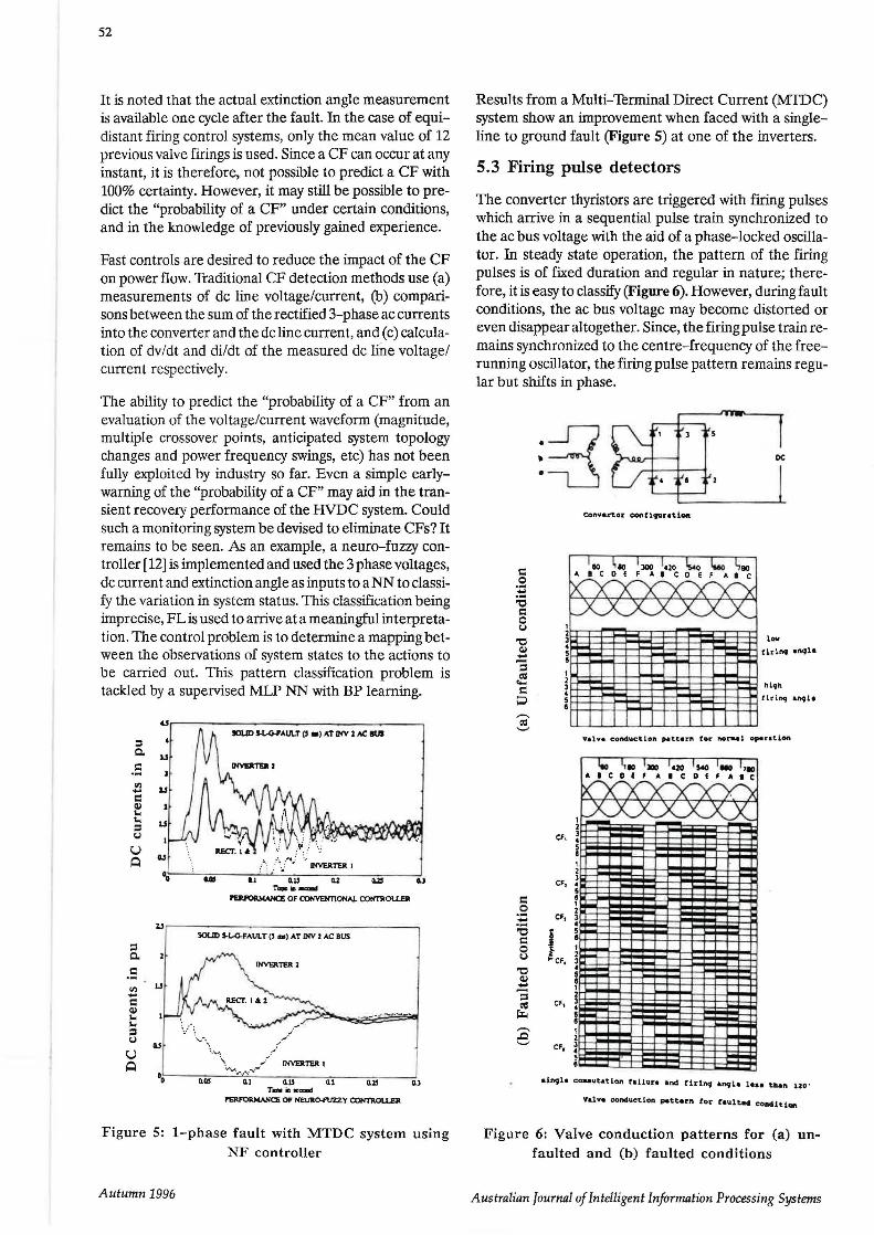
5.3 Firing pulse detectors
The converter thyristors are triggered with firing pulses which arrive in a sequential pulse train synchronized to the ac bus voltage with the aid of a phase-locked oscillator. In steady state operation, the pattern of the firing pulses is of fixed duration and regular in nature; therefore, it is easy to classify (Figure 6). However, during fault conditions, the ac bus voltage may become distorted or even disappear altogether. Since, the firing pulse train remains synchronized to the centre-frequency of the freerunning oscillator, the firing pulse pattern remains regular but shifts in phase.
= .::2 .... ;e = 0 u
'"0 (I) .... :; ell
~';!;.
---.c ......,
DC
Ieo 1110 llaa l,lO T s.o 1110 1,10
~ Cf, ~~ ~ I-I--5 a I 2
CF1 3 • 5 a , 2
CF1 3 • I ~CF,
5 I , 2 3 • 5 I , 2
Cf1 3 • 5
, 2
CF,
•ift9'1• eo-ut&tion raUure and tirincJ angle ltsa tb.an uo ·
Yalv• conch1et1on pattern fo'C' ta\l.lted. concUtiOft
Figure 6: Valve conduction patterns for (a) unfaulted and (b) faulted conditions
Australian Journal of Intelligent Information Processing Systems

However, due to the requirements of thyristor valve protection units when the valves are conducting fault currents, the duration of these firing pulses may also become elongated. A combination of the varying phase shift and pulse elongation results in an irregular pattern which is more difficult to classify. A trained NN offers many advantages for the indication of any error in the firing pulse unit, (i.e. false sequences, missing pulses, low-strength of firing pulses, noise pollution etc). Such FDD units can be extremely useful during commissioning as well as in operational modes.
5.4 Non-linearities in components
The performance of HVDC systems in particular, and ac systems in general, are affected by various non-linear power system components such as transformers and surge arresters. Such components have their characteristics which are known and predictable. NNs have been applied to the fault detection in transformers. The presence of harmonics and inter-harmonics can provide clues to the mal-operation of certain equipments, or even guide in the selection of operational configurations.
5.4 Converter faults
Each converter valve is comprised of many tens of thyristors connected in series. Each thyristor is served by several passive components [13] to ensure that voltage sharing and to protect individual thyristors from overvoltage, excessive dv/dt and di/dt stresses (Figure 7). The saturating reactors protect the thyristor from damage immediately after firing. Direct voltage is equalized across the thyristor string by a de grading resistor which acts as a voltage divider. Dynamic voltages are equalized by a RC snubber circuit. And a capacitive grading branch is used to protect against switching surges.
Saturating Reactors
Breakover cliocle
Firing Databack
Figure 7: Electrical circuit of one thyristor level in converter valve design [13]
The command to fire a thyristor is emitted by the Valve Base Electronics (VBE) unit at earth potential and fed via a fibre-optic cable to each thyristor operating at high voltage. The energy to fire the thyristor is derived from the grading circuit during the off-state interval.
Australian Journal of Intelligent Information Processing Systems
53
Thyristors can be easily damaged by excessive forward voltage or forward dv/dt, especially at the elevated junction temperatures which occur during faults. They are particularly vulnerable during the recovery period immediately after turn-off when, even a modest forward voltage may cause uncontrolled conduction. Protection is af-forded by firing the thyristor into conduction independently from the main control system. In marginal cases, some thyristors may block forward voltage whilst others may not; in which case, the blocking thyristors would experience excessive voltages and suffer the consequences. A protective firing system, based on a Breakover Diode (BOD), is used to re-trigger the thyristor under such circumstances. The BOD can operate repeatedly in case of failure of the VBE.
NNs can be used to classify the firing patterns emanating from the controllers, and the voltages monitored across each thyristor valve for fault indication.
6.0 TEST CASES
Usually, difficulty is experienced in discriminating between line-to-line fault (LLF) and double line-to-ground faults (DLGF). In method 1, suggested in [4], the NN of Figure 8 was unable to discriminate between these two types of faults (Figure 9).
OUTPUTS
INPUTS
rms values
Figure 8: Neural network for test case of method 1
However, in method 2 [4] additional information i.e. phase angles between the three phases are provided, to enable the NN to make its decision. The concept of using the phase shift of ± 120 degrees between the three phases is novel. Hence, one additional NN per phase (Figure 10) is needed to detect these faults. These phase detector networks are fed with the following inputs per phase (i.e. for phase A): (a) rms phase voltage, i.e. Va, in pu, (b) angle between phases A and B, i.e. Ph A-B, in pu (c) angle between phases A and C, i.e. Ph A-C, in pu. At its output, one processing element is attached in an additionallayer. This element is connected with fixed weights such that the output from the Phase Detector Network is: (a) 1, when thereisnofaultNF, (b)-1, when there is aline to line fault LLF, (c) 0, when there is a single line to ground fault SLGF. These outputs (X, Y and Z) for the three phases, are then connected to the main NN. In Fig· ure 11, the results of this NN test case are shown and this time the correct distinction is made.
Autumn 1996

54
a) i!. o
·•
b)l:" ·:~ ·:M
a) Phase B vollage at rectifier. b) Phase C voltage at rectifier bus. c) Phase B voltage (nns value). d) Neural Network outputs.
--- NoFault. -- Faull (type indicated).
i!.·~. ·n c) o~ . • ' i d)
0 0.1 0.1
llmo(tee) .
O.l
0
0 0.1 0.1 lime( tee)
O.l
Case ollLF with Method 1. Case ol DLGF with Method 1.
Figure 9: Case of (a) LLF and (b) DLGF with method 1
r--------, '---+--~J z I
PhA-C Phase A
INPUTS
LLFc 1 SLGFc 1
I I I I I I I
1 Phase C 1 L--------....1
Phase Detector Network
V de
Figure 10: Neural Network for test case of method 2
7.0 CONCLUSIONS
This paper has focused on FDD applications in the HVDC systems since such systems are fast-acting and can benefit from the real-time fault monitoring, diagnosis, control and protection actions [19]. The paper has been limited to FDD aspects only; the control and protection aspects have not been fully explored here.
Results from the NN based monitoring techniques are very encouraging, as indicated by hardware implementa-
Autumn 1996
tions descnbed elsewhere [14,15]. The recent implementation of a complete station based FDD system [16] points to promising future industrial applications.
Intelligent systems are still evolving in practice. A recent development is in the use of constructive RBF NNs. These yield the most optimum size of network, with the network development taking place during the training of the NN commencing from the initial configuration having only two neurons in the hidden layer. The main requirement, from the FDD point of view, is that the NN configuration should be unambiguous, fast, able to operate even on corrupted data and able to incorporate system growth. Categorical identification of the type of fault and its location is also very important. More particularly, the FDD of evolving faults and its real-time operation will be an essential future requirement.
A particular challenge for the control and protection applications in an HVDC converter remains in the area of prediction and detection of a Commutation Failure (CF). The early prediction of a CF can be extremely useful in enhancing the dynamic performance of an HVDC system. The early prediction of a CF will require considerable understanding of the fundamental CF process in a thyristorvalve. Such an understanding presently does not exist, and it is therefore an ideal application for a NN based technique.
8.0 ACKNOWLEDGEMENTS
The authors gratefully acknowledge the many contributions of their colleagues amongst others: N. Kandil, R. V. Patel, K. Khorasani, V. Shyam, K. Swarup, R. Jayakrishna, F. Ndeh-Che, and T. Chari.
Australian Journal of Intelligent Information Processing Systems

55
•1 -- Phase A voltaae (nns)
--- Anj!lc between phase.• A and B (lpu • 120 dcgs) 0 b) - Phase 8 voltage (rms)
--- Angle between phases B and C (I pu • 120 degs)
l c) -- Phase C voltaae (rms)
a) l J F ' -,; I
b). :r~ <)·:~ ·:~
--- Anslc between phases C and A (lpu • 240 dcp) d) ~ural Network outputs,
--- No Fault,
-- Faull (type indicated).
d)
0 0.1 o: time( IlK)
O.J 0 0.1 0.2
time(ooc)
0.3
Case of LLF with Method l Case or DLGF with Method l
Figure 11: Case of (a) LLF and (b) DLGF with method 2
9.0 REFERENCES
(1) K.Swarup, H.Chandrasekharaiah, "PDES: Fault diagnosis expert systems for HVDC systems", Second Symp. on Expert Systems for HVDC Systems, Univ. of Washington. 1989. pp 296-302.
[2] K.Swarup, H.Chandrasekharaiah, "Pattern di-rected inference system for fault classification and analysis", Sixth National Power Systems Conf. Bombay, June 1990, pp 145-150.
[3) K.S.Swarup and H.S. Chandrasekharaiah, "Fault Detection and Diagnosis of Power Systems using Artificial Neural Networks", Proc. Int. Forum on Appl. of NNs to Power Systems, Edited by M.ElSharkawi & R.Marks, Seattle, Washington, July 23-26, 1991.
[4] N.Kandil, V.K.Sood, K.Khorasani and R.V.Patel, "Fault Identification in an AC-DC transmission system using Neural Networks", IEEE Trans. on Power Systems, Vol. 7, No.2, May 1992.
[5] T.Grigoriu, V.K.Sood, R.V.Patel and K.Khorasani, "Fault Identification in a series compensated AC line using Neural Networks", IEEE Canadian Conf. on Electrical and Computer Engineering, Toronto, Sept, 1992.
[6] V.K.Sood, N.Kandil, R.V.Patel and K.Khorasani, "Comparative evaluation of Neural Network Based and PI Current Controllers for HVDC Transmission Systems", IEEE Trans. on Power Electronics, Vol.9, No.3, May 1994.
Australian Journal of Intelligent Information Processing Systems
[7] "Artificial Neural Networks for power systems: A literature survey", CIGRE TF 38-06-06, Vol. 1, No. 3, Dec 1993. Convener: D. Niebur.
[8] L.Lai, N.Che, K. Swarup, H.Chandrasekharaiah, "Fault Diagnosis for HVDC systems using NNs", July 1993, 12th IFAC World Congress, Australia.
[9] L.L.Lai, F.Ndeh-Che, T.Chari, P.Rajroop and H.S.Chandrasekharaiah, "HVDC systems fault diagnosis with Neural Networks", EPE'93, Brighton, UK, pp 145-150, 1993.
[10] L.L.Lai, F.Ndeh-Che, and T.Chari, "Fault Identification in HVDC systems with Neural Networks", lEE Second Int. Conf. on Advances in Power System Control, Operation and Management, Dec. 1993, Hong Kong. pp 231-236.
[11] K.Swarup, H.Chandrasekharaiah, et al ,"Application of NNs to fault diagnosis for HVDC systems", Proc. of Int. Conf. on NNs and Genetic Algorithms, Springer-Verlag, 199 3.
[12] R. Jayakrishna, H.S.Chandrasekharaiah and K.G.Narendra, "Neuro-Fuzzy Controller for enhancing the performance of extinction angle control of inverters in a MTDC-AC system, 2nd Int. Forum on Applications of Neural Networks to Power Systems, Yokohama, Japan, April 1993, Eds. Y.Tamaura, H.Suzuki and H.Mori.
[13] J.D.Wheeler, J.L.Haddock, "Chandrapur Backto-Back HVDC scheme in India", ICPST'94, Beijing, China.
[14] T.Dalstein and B.Kulicke, "Neural Network Approach to Fault Classification for High Speed Pro-
Autumn 1996

56
tective Relaying", IEEE Trans. on Power Delivery, April 1995, Vol. 10, No.2, pp 1002-1011.
[15] T.S .Sidhu, H.Singh and M.Sachdev, "Design, Implementation and Testing of an Artificial Neural Network based Fault Direction Discriminator for Protecting Transmission Lines", IEEE Trans. on Power Delivery, April 1995, Vol. 10, No.2, pp 697-706.
[16] H .Yang, W.Chang and C.Huang,"On-line Fault Diagnosis of Power Substation using connectionist Expert System", IEEE Trans. on Power Systems, Feb . 1995, Vol. 10, No.1, pp 323-331.
[17] I.Kamwa, R.Grondin, V.K.Sood, C.Gagnon, V.T.Nguyen and J.Mereb, "Recurrent Neural Networks for Phasor Detection and Adaptive Identification in Power System Control and Protection", IEEE Instrumentation Society, Annual Meeting: Integrating Intelligent Instrumentation and Control, 22-25 April 1995, Boston, MA.
[18] L. L. Lai, et al "Computer assisted learning in power system relaying', IEEE Transactions on Education, Vol 38, No 3, August 1995.
[19] V. Shyam, H. S. Chandrasekharaiah and L. L. Lai, "Real-time intelligent control for a multi-terminal direct current transmission system", Proc. of the Sixth European Conf. on Power Electronics and Applications, EPE, Spain, Sept 1995.
[20] E. Georges, L. L. Lai, F. Ndeh-che and H. Braun, "Implementation of neural networks with VLSI", Proc. of the Fourth lnt. Conf. on Neural Networks, lEE, Cambridge, UK, June 1995.
[21] K.Narendra, V.K.Sood, R.Patel and K.Khorasani, "A nemo-fuzzy VDCL unit to enhance the performance of an HVDC system", IEEE Canadian Conf. on Electrical and Computer Engineering, 5-8 Sept. 1995, Montreal.
[22] K.Narendra, V.K.Sood, et al, "Application of a Radial Basis Function (RBF) Neural Network for Fault Diagnosis in a HVDC System", lnt. Conf. on Power Electronics, Drives and Energy Systems for Industrial Control, 8-11 Jan 1996, N.Delhi, India.
10.0 BIOGRAPHIES
V.K.Sood
Professor Sood obtained the B.Sc. (First Class Honors) degree in Electrical Engineering from University College, Nairobi (Kenya) in 1967, the M.Sc. degree from University of Strathclyde, Glasgow (Scotland) in 1969 and the Ph.D. degree from University of Bradford (England) in 1977.
From 1969-76, he worked at the Railway Thchnical Centre, Derby (UK). Since 1976, he has been at the Hy-
Autumn 1996
dro Quebec research institute (IREQ) in Varennes, Quebec working with the real-time simulator. His present research interests include HVDC transmission, Forced Commutated converters, Neural Network applications to power systems and analog/numerical power system simulation techniques.
He is a Senior Member of the IEEE, Member of the lEE (UK) and a Registered Professional Engineer in the Province of Quebec. He is an Adjunct Professor in the Department of Electrical and Computer Engineering at Concordia University, Montreal. Presently he is the Chairman of the IEEE Power Engineering Chapter and Industry Applications Chapter of the IEEE Montreal section, the Managing Editor (1996-98) for the IEEE Ca-nadian Review, member of CIGRE WG 14.22 and the founding Chairman (1991-1993) for the Intl. Neural Network Society (Canada SIG).
H.S. Chandrasekharaiah
Dr. H.S. Chandrasekaraiah obtained his Ph.D. degree from the Indian Institute of Science, Bangalore (India) and presently he is working as a Professor in its High Voltage Engineering Department. His research interests include HVDC transmission, Fault Diagnosis in power systems and the application of intelligent systems to power systems. He has more than 150 research publications in these areas.
He was a visiting professor at TU Dresden, Germany during 1989 and City University, London during 1994. He is a Senior Member of IEEE, member of CIGRE TF 38.06.06, and a Fellow of the Inst. of Engineers, India and the Society of Power Engineers. His papers have received several awards from the Inst. of Engineers and Central Board of Irrigation and Power.
L.L. Lai
Loi Lei Lai (Senior Member, IEEE) was born in Hong Kong. He joined Staffordshire Polytechnic as a Senior Lecturer in 1984. He was an Industrial Fellow to both the GEC Alsthom Turbine Generators Ltd. and GEC Alsthom Engineering Research Centre from Jan-Oct 1987. He was also a part-time Consultant to CEGB from 1985 to 1987. Dr. Lai took up an academic post at City University in 1989. In Apri11991, he established the Power and Energy Systems Research Unit and is the Unit Director. He is also head of the High Voltage Laboratory since April 1991. Dr Lai is also an Honorary Professor at the Beijing Power Engineering and Economics Institute (now known as the North China University of Electric Power), China. He was a Visiting Professor at the Tokyo Metropolitan University, Japan as from July to Oct 1995. He has published over 40 papers in the IEEE, lEE, IFAC, CIGRE and other journals and conference proceedings. He is a Chartered Electrical Engineer and a Corporate Member of the lEE, UK. His main research interests are in Power & Energy Systems, High Voltage Engineering, Power Electronics and Artificial Neural Networks.
Australian foumal of Intelligent Information Processing Systems