Fault Detectability in DWDM - Toward Higher Signal Quality & System Reliability
170
Transcript of Fault Detectability in DWDM - Toward Higher Signal Quality & System Reliability

7/22/2019 Fault Detectability in DWDM - Toward Higher Signal Quality & System Reliability
http://slidepdf.com/reader/full/fault-detectability-in-dwdm-toward-higher-signal-quality-system-reliability 1/169

7/22/2019 Fault Detectability in DWDM - Toward Higher Signal Quality & System Reliability
http://slidepdf.com/reader/full/fault-detectability-in-dwdm-toward-higher-signal-quality-system-reliability 2/169
FAULT DETECTABILITY
IN DWDM
7/22/2019 Fault Detectability in DWDM - Toward Higher Signal Quality & System Reliability
http://slidepdf.com/reader/full/fault-detectability-in-dwdm-toward-higher-signal-quality-system-reliability 3/169
IEEE Press
445 Hoes Lane, P.O. Box 1331
Piscataway, NJ 08855-1331
IEEE Press Editorial BoardStamatios V. Kartalopoulos, Editor in hief
M. Akay
J. B. Anderson
J. Baker
J. E. Brewer
M. Eden
M. E. El-Hawary
R. J. Herrick
R. F. Hoyt
D. Kirk
Kenneth Moore, Director of IEEE Press
Catherine Faduska, Senior EditorMarilyn G. Catis, Marketing Manager
Anthony VenGraitis, Project Editor
Cover design: Caryl Silvers, Silvers Design
Technical Reviewers
M. S. Newman
M. Padgett
W. D. Reeve
G. Zobrist
Andy Quinn, Bookham Technology
Nim K. Cheung, Telcordia Technologies, Morristown, NJ
Books of Related Interest from the IEEE Press
INTRODUCTION TODWDM TECHNOLOGY:Data in a Rainbow
Stamatios V. Kartalopoulos
2000 Hardcover 274 pp IEEE Order No. PC5831 ISBN 0-7803-5399-4
UNDERSTANDING SONETISDH AND ATM: Communications Networks for the Next
Millennium
Stamatios V. Kartalopoulos
A volume in the IEEE Press Understanding Science Technology Series
1999 Softcover 288 pp IEEE Order No. PP5399 ISBN 0-7803-4745-5

7/22/2019 Fault Detectability in DWDM - Toward Higher Signal Quality & System Reliability
http://slidepdf.com/reader/full/fault-detectability-in-dwdm-toward-higher-signal-quality-system-reliability 4/169
FAULT DETECTABILITY
IN DWDM
Toward igh r Signal Quality
System Reliability
Stamatios KartalopoulosLucent Technologies, Inc.
Bell Labs Innovations
Holmdel, NJ
IEEE
PRESS
The Institute of Electrical and Electronics Engineers, Inc., New York

7/22/2019 Fault Detectability in DWDM - Toward Higher Signal Quality & System Reliability
http://slidepdf.com/reader/full/fault-detectability-in-dwdm-toward-higher-signal-quality-system-reliability 5/169
This book and other books may be purchased at a discountfrom the publisher when ordered in bulk quantities. Contact:
IEEE Press Marketing
Attn: Special Sales
445 Hoes Lane, P.O. Box 1331Piscataway, NJ 08855-1331
Fax: 1 732 981 9334
For more information about IEEE Press products, visit the
IEEE Online Store Catalog: http://www.ieee.org/store.
© 2001 by Lucent Technologies. All rights reserved.600 Mountain Avenue, Murray Hill, NJ 07974-0636.
ll rights reserved. No part of this book may be reproduced in any form,
nor may it be stored in a retrieval system or transmitted in any form,
without written permission from the publisher.
Printed in the United States of America.
10 9 8 7 6 5 4 3 2
ISBN 0-7803-6044-3IEEE Order No. PC5886
Library of Congress Cataloging-in-Publication Data
Kartalopoulos, Stamatios V.
Fault detectability in DWDM: toward higher signal quality system reliability /
Stamatios V. Kartalopoulos.
p. em.
Includes bibliographical references and index.
ISBN 0-7803-6044-31. Optical communications. 2. Multiplexing. 3. Signal processing-Digital
techniques. 4. Fault location (Engineering) I. Title.
TK5103.59.K34 2001
621.382 7-dc21 00-053533

7/22/2019 Fault Detectability in DWDM - Toward Higher Signal Quality & System Reliability
http://slidepdf.com/reader/full/fault-detectability-in-dwdm-toward-higher-signal-quality-system-reliability 6/169
To my parents for my first breath in life,
To my first teacher for her inspiration,
To my wife, Anita, for her love and encouragement,
To my children Vasilis (William) and Stephanie
for the many joys they have brought me,
And to all those who have enriched my life.

7/22/2019 Fault Detectability in DWDM - Toward Higher Signal Quality & System Reliability
http://slidepdf.com/reader/full/fault-detectability-in-dwdm-toward-higher-signal-quality-system-reliability 7/169
CONTENTS
Preface xiii
Acknowledgments xv
Introduction xvii
Chapter 1 Properties of Light and Matter 1
1.1 Introduction 1
1.2 Nature of Light 1
1.2.1 Wave Nature of Light 2
1.2.2 Particle Nature of Light 3
1.3 Reflection, Refraction, and Diffraction 3
1.3.1 Reflection and Refraction: Index of Refraction 3
1.3.2 Diffraction 4
1.3.3 Gaussian Beams 4
1.4 Polarization of Light 4
1.4.1 Faraday Effect 5
1.5 Propagation of Light 5
1.5.1 Phase Velocity 6
1.5.2 Group Velocity 6
1.6 Fiber Birefringence and Polarization 7
1.7 Dispersion 8
1.7.1 Modal 8
1.7.2 Chromatic Dispersion 8
1.7.3 Polarization Mode Dispersion 9
1.8 Fiber Attenuation and Loss 9
1.9 Fiber Spectrum Utilization 101.9.1 Spectral Bands 10
1.9.2 ITU-T C-Band Nominal Center Frequencies 10
vii
7/22/2019 Fault Detectability in DWDM - Toward Higher Signal Quality & System Reliability
http://slidepdf.com/reader/full/fault-detectability-in-dwdm-toward-higher-signal-quality-system-reliability 8/169
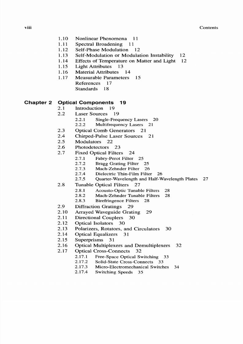
viii
1.10 Nonlinear Phenomena 11
1.11 Spectral Broadening 11
1.12 Self-Phase Modulation 121.13 Self-Modulation or Modulation Instability 12
1.14 Effects of Temperature on Matter and Light 12
1.15 Light Attributes 13
1.16 Material Attributes 14
1.17 Measurable Parameters 15
References 17
Standards 18
Contents
Chapter 2 Optical Components 9
2.1 Introduction 19
2.2 Laser Sources 19
2.2.1 Single-Frequency Lasers 20
2.2.2 Multifrequency Lasers 21
2.3 Optical Comb Generators 21
2.4 Chirped-Pulse Laser Sources 21
2.5 Modulators 22
2.6 Photodetectors 23
2.7 Fixed Optical Filters 24
2.7.1 Fabry-Perot Filter 25
2.7.2 Bragg Grating Filter 25
2.7.3 Mach-Zehnder Filter 26
2.7.4 Dielectric Thin-Film Filter 26
2.7.5 Quarter-Wavelength and Half-Wavelength Plates 27
2.8 Tunable Optical Filters 27
2.8.1 Acousto-Optic Tunable Filters 28
2.8.2 Mach-Zehnder Tunable Filters 28
2.8.3 Birefringence Filters 28
2.9 Diffraction Gratings 29
2.10 Arrayed Waveguide Grating 29
2.11 Directional Couplers 30
2.12 Optical Isolators 30
2.13 Polarizers, Rotators, and Circulators 30
2.14 Optical Equalizers 31
2.15 Superprisms 31
2.16 Optical Multiplexers and Demultiplexers 32
2.17 Optical Cross-Connects 322.17.1 Free-Space Optical Switching 33
2.17.2 Solid-State Cross-Connects 33
2.17.3 Micro-Electromechanical Switches 34
2.17.4 Switching Speeds 35

7/22/2019 Fault Detectability in DWDM - Toward Higher Signal Quality & System Reliability
http://slidepdf.com/reader/full/fault-detectability-in-dwdm-toward-higher-signal-quality-system-reliability 9/169
Contents
2.18
2.19
2.20
2.21
Optical Add-Drop Multiplexers 36
Optical Amplifiers 36
2.19.1 SOAs 372.19.2 Rare-Earth Doped Fiber Amplifiers 38
2.19.3 Raman Amplifiers 39
Classification of Optical Fiber Amplifiers 39
Wavelength Converters 40
References 40
Standards 48
ix
Chapter 3 Parameters Affecting the Optical DWDM Signal 53.1 Introduction 51
3.2 Component Parameters 51
3.2.1 Parameters Common to All Optical Components 52
3.2.2 Parameters Specific to Branching Optical
Components 53
3.2.3 Parameters Specific to MuxlDemux Optical
Components 53
3.2.4 Parameters Specific to Optical Attenuators 53
3.2.5 Parameters Specific to Optical Filters 53
3.2.6 Parameters Specific to Optical Switches 54
3.2.7 Parameters Specific to Passive Dispersion
Compensation 54
3.2.8 Parameters Specific to Fibers 54
3.2.9 Parameters Specific to Light Sources 55
3.2.10 Parameters Specific to Receivers 55
References 40
Standards 48
Chapter 4 Faults Affecting the Optical DWDMSignal 59
4.1 Introduction 59
4.2 Components 61
4.3 Filters: Fabry-Perot (Passive, Fixed) 61
4.4 Filters: Fiber Bragg Grating (Passive, Fixed) 63
4.5 Filters: Chirped FBG (Passive, Fixed) 64
4.6 Filters: Acousto-Optic Tunable Ti:LiNb03 66
4.7 SOA: InGaAsP 68
4.8 OFA: Factors Affecting Integrity and Quality of Signal 704.9 OFA: Single Pump 71
4.10 OFA: Double Pump 73
4.11 Mux/Demux 75
4.12 OXC: MEMS 76

7/22/2019 Fault Detectability in DWDM - Toward Higher Signal Quality & System Reliability
http://slidepdf.com/reader/full/fault-detectability-in-dwdm-toward-higher-signal-quality-system-reliability 10/169
x
4.13
4.14
4.154.16
4.17
4.18
4.19
OXC: LiNb03 78
OXC Liquid Crystal 79
OADM: LiNb03 Based 81OADM: MEMS with Grating 82
Transmitter: Laser 83
Receiver: PIN Diode 84
Fiber: Single Mode 85
References 87
Standards 94
Contents
Chapter 5 Fault Correlation 97
5.1 Introduction 97
5.2 Correlation of Faults and Component Parameter
Changes 97
5.3 Open Issues: Nonlinear Effects 100
References 101
Standards 02
Chapter Toward DWDM Fault Management and Current
Issues 5
6.1 Introduction 105
6.2 Toward Fault Management 107
6.2.1 The Network Level 108
6.2.2 The NE Level 108
6.3 Current Issues 1096.3.1 Optical Supermaterials 109
6.3.2 Integration 109
6.3.3 Lasers and Receivers 109
6.3.4 Line-Coding Techniques 110
6.3.5 Optical Cross-Connect 110
6.3.6 Optical Add-Drop Multiplexers 110
6.3.7 Optical Memories and Variable Delay Lines 111
6.3.8 Nonintrusive Optical Monitoring 111
6.3.9 DWDM System Dynamic Reconfigurability 111
6.3.10 Optical Backplanes 111
6.3.11 Fault Management Standards 111
6.3.12 Network Issues 112
6.3.13 Opaque Systems 113

7/22/2019 Fault Detectability in DWDM - Toward Higher Signal Quality & System Reliability
http://slidepdf.com/reader/full/fault-detectability-in-dwdm-toward-higher-signal-quality-system-reliability 11/169
Contents
6.4 Engineering DWDM Systems: Conclusion 113
References 114
Standards 116
Acronyms 9
Index 49
About the Author 55
xi

7/22/2019 Fault Detectability in DWDM - Toward Higher Signal Quality & System Reliability
http://slidepdf.com/reader/full/fault-detectability-in-dwdm-toward-higher-signal-quality-system-reliability 12/169
PREFACE
For more than 2500 years, light has been used in communications. In those days, light
towers were used to send quickly a brief encoded message from point A to point B and
across the land, such as the enemy is approaching or festivitieswill start next month.
Communicating with light in open space, although a seemingly simple operation,
had its own problems. For example, when a robust code was used so that the enemy
could not easily decode the message, many factors had to be considered. The light
should be intense enough so that it could be seen from a distant tower. The tower
should be strategically positioned and be tall enough so that trees and low hills couldnot obstruct the line of sight. The atmosphere should be clear so that heavy rain or
fog could not absorb the optical signal. The towers should be adequately equipped
and staffed. A synchronization mechanism should exist so that the receiving tower
would know when a message was about to be transmitted. A protocol should be fol
lowed so that when the received message was not understood, a request to retransmit
could be made. And, of course, there were many maintenance functions that are not
too difficult to imagine. As problematic as it was, this method of optical communi
cation lasted until a couple of centuries ago.
Throughout history many scientists made significant contributions in the opticaldomain. The reflectivity and refractivity of light were studied, and in ancient times
the paraboloid reflector was studied and invented. Although in antiquity glass was not
as clear as it is today, it generated a lucrative industry primarily in the making of jew
elry and of perfume vessels and in other more exotic applications of refracting light
to perhaps form the first lens systems. Thus, glass evolved and in modem times it is
a ubiquitous material. It would be very difficult today to envision life without glass.
Only in the far future might we envision ourselves without it, when high-technology
transparent plastics, better and more cost-efficient than glass, might replace it.
Today, glass is used in a myriad of ways, including optical communication lines.Glass-based fiber is wrapped around the globe like a ball of yarn connecting all con
tinents and transmitting enormous amounts of data at the speed of light. Currently,
xiii

7/22/2019 Fault Detectability in DWDM - Toward Higher Signal Quality & System Reliability
http://slidepdf.com/reader/full/fault-detectability-in-dwdm-toward-higher-signal-quality-system-reliability 13/169
xiv Preface
a single fiber can transmit the contents of hundreds of thousands of volumes of data
within a second.
Since glass and optical components provide key functionality in communications, there are visions of an all-optical network able to carry unprecedented amounts
of information over many hundreds of thousands of kilometers without converting
the optical signal into electronic and back to optical. The only electrical-to-optical
conversion, and vice versa, will be at the end terminals, at the source and at the sink
of the signal, respectively.
ABOUT THIS BOOK
My interest in the field of optical communication has culminated in two books, Intro
duction to DWDM Technology: Data in a Rainbow (IEEE Press, 2000) and Under
standing SONETISDH and ATM: Communications Networks for the Next Millenium
(IEEE Press, 1999).Recently, I havebeen working on the evaluation of faults and degra
dations of optical components in multiwavelength systems and networks, on fault de
tectability and localization, and also on the necessary remedial actions. Degradations
and faults of optical components is an integral part of system and network design that
cannot be overlooked.For example, degradations and faults affect the quality of the op
tical signal and thus the optical signal-to-noise ratio, the optical bit error rate, and the
fiber span without amplification. In addition, they affect the selection of the forward error correction FEe code, the receiver design, fail-safe mechanisms, monitoring strate
gies and remedial actions, and in general fault management, as well as the system and
network robustness.At the ultrahigh bit rates and aggregate bandwidth used today, such
degradations and faults should be identified as soon as they happen and remedied.
My personal notes and several documents that I have published provided the
source material for this book. In many respects, this book is the continuation of In
troduction to DWDM Technology:Data in a Rainbow, which describes the properties
of light, its interaction with matter, and how optical components work in optical com
munications, such as filters, multiplexers, optical switches, and many others. Thisbook provides only a brief overview of key principles and optical components and fo
cuses on the understanding of optical fault and degradation mechanisms (detection, lo
calization, and remedial action) that affect the optical signal and the operation of the
DWDM system and perhaps of the network. The understanding of optical faults and
degradations is important in the architectural design of optical systems and networks,
in the design of complex optical components, in fault management of dense wavelength
division multiplexing (DWDM) systems and networks, and in the development of stan
dards. DWDM technology is still evolving, and as such, the reader interested in the
details of DWDM is strongly recommended to consult the most current updated standards. I wish you happy and easy reading.
Stamatios V. Kartalopoulos, Ph.D.
Lucent Technologies, Inc.
Bell Labs Innovations

7/22/2019 Fault Detectability in DWDM - Toward Higher Signal Quality & System Reliability
http://slidepdf.com/reader/full/fault-detectability-in-dwdm-toward-higher-signal-quality-system-reliability 14/169
ACKNOWLEDGMENTS
Throughout time, few achievements of note have been the product of individual ef
fort. Instead, they have been accomplished through the efforts of many. Similarly,
the fruition of this book would be impossible without the cooperation, diligence,
understanding, and encouragement of a number of people. First, I would like to ex
tend my thanks and appreciation to my wife, Anita, for her patience and encour
agement. I would also like to extend my thanks to my colleagues, for creating an
environment that fosters learning, collaboration, and encouragement. In particular,
I would like to thank Sjoerd Last and Harvey Epstein for stimulating discussion onthis subject as well as the anonymous reviewers for their comments and construc
tive criticism and to the IEEE Press staff for their enthusiasm, suggestions, creativ
ity, and project management. Finally, I am grateful to all those who diligently
worked on all execution phases of this production.
Stamatios V. Kartalopoulos, Ph.D.
Lucent Technologies, Inc.
Bell Labs Innovations
xv
7/22/2019 Fault Detectability in DWDM - Toward Higher Signal Quality & System Reliability
http://slidepdf.com/reader/full/fault-detectability-in-dwdm-toward-higher-signal-quality-system-reliability 15/169
INTRODUCTION
Since early history, the fascination with light has sparked the curiosity and imagi
nation of mankind. It was so difficult to explain its origin that many ancient cul
tures resorted to myths; according to one, Prometheus brought fire to mankind and
Apollo was the son of Light (Sun); and others attributed divine properties to crys
tals with irridescent properties. Most ancient theologies linked light with the divine,
and many modern ones still do.
Many scientists have attempted to provide a scientific interpretation of the ori
gin of light; they linked light with atomic energy levels. According to this model,light is the result of electrons or energy states when they jump from a higher state
to a lower one. Then, energy is emitted in the form of an electromagnetic wave,
which may be in the visible or invisible spectrum. However, this electromagnetic
energy is special; the wave is self-propelled and propagates even in emptiness, a
concept that has many believers and also many skeptics. In addition to being a wave,
light also exhibits particle properties. For instance, when light falls on a specially
prepared wheel, it makes the wheel spin (Compton s experiment). However, the no
tion of two natures coexisting in light is still difficult to grasp, even though Einstein
has linked energy with mass E = me ). Despite this, the fact remains that sciencehas demystified the divinity of crystals, and semiconductor devices (the laser)
generate a photonic beam at command. This beam is so powerful and so narrow
that it can be applied in a wide range of applications-in communications, in land
surveys, and in surgical operations, to mention a few.
Optical waves extend over a wide spectrum of frequencies (or wavelengths).
However, this spectrum is not entirely visible to the human eye. What we call vis
ible light is in a narrow range of wavelengths, from 0.7 u.m (700 nm) to 0.4 urn
(400 nm), from the deep red to the dark violet-blue; this is so because of the re
sponse range of the human retinal receptors (the cones and the rods). Had we asked
a cat or an owl how things appear through their own eyes, we would certainly get
a different answer. The optical spectrum used in high-speed fiber communications
xvii

7/22/2019 Fault Detectability in DWDM - Toward Higher Signal Quality & System Reliability
http://slidepdf.com/reader/full/fault-detectability-in-dwdm-toward-higher-signal-quality-system-reliability 16/169
xviii Introduction
is beyond the visible spectrum; it is in the range of 1200-1700 nm for reasons dic
tated by the optical medium and the components.
In optical communications, bit rates of up to 40 Gbps are currently used in asingle-mode fiber, and bit rates higher than that have been demonstrated. At 40
Gbps, half a million simultaneous telephone conversations can be supported. Dense
wavelength-division multiplexing (DWDM) technology increases the aggregate
bandwidth to terabits per second. DWDM systems with more than a hundred wave
lengths in the same fiber are here, and DWDM technologies with 206 wavelengths
or more have been experimentally demonstrated. An 80-wavelength DWDM system
at 40 Gbps per wavelength has an aggregate bandwidth of 3200 Gbps, a bandwidth
that can transport in a single fiber the contents of many thousand volumes of an en
cyclopedia in a second. Therefore, the optical signal that carries such vast amounts
of information should be safeguarded to maintain an acceptable quality level
throughout its complete traveled path, through fibers and optical components.
However, one should not lose sight of the fact that:
• Light interacts with matter as well as with itself.
• The parameters of many optical components depend on temperature, stress,
time (aging), and in some cases electrical or magnetic fields.
• Optical components degrade or fail and these degradation or failures are notobserved in a traditional manner, as are their electronic counterparts.
All these degradations and failures may have a direct effect on the quality of
the signal and/or the availability of the system/network and, most importantly, the
availability of the service provided to the end user. Therefore, imminent degrada
tions and faults must be promptly identified and either remedied or bypassed, else
a tremendous amount of data may be lost or not delivered, considering the amount
of data that bandwidths at the terabits-per-second level carry. That is, in a multi
fiber and multiwavelength network, the availability of terabits-per-second band
width may not be as critical as it may be the inability to transport this bandwidth
due to faults and degradations. Consequently, photonic degradations and failures
in DWDM systems and networks should be thoroughly understood to assist in an
efficient fault detection, localization, restoration, and avoidance strategy that as
sures the quality of signal and a reliable communications network.
IN THIS BOOK
The objective of this book is to enhance the understanding of degradation and fail
ure mechanisms of optical components and to assist in drafting fault detection
guidelines that could be used to design a more robust multiwavelength optical sys-

7/22/2019 Fault Detectability in DWDM - Toward Higher Signal Quality & System Reliability
http://slidepdf.com/reader/full/fault-detectability-in-dwdm-toward-higher-signal-quality-system-reliability 17/169
Introduction xix
tern and network. A thorough overview of optical components can be found in the
book, Introduction to DWDM Technology: Data in a Rainbow, (IEEE Press, 2000)
by the same author, as well as in other publications.This book is organized into six chapters, and progressively introduces the
subject of photonic faults and degradations. Chapter 1 reviews the properties of
light and optical communications; Chapter 2 reviews the optical components;
Chapter 3 describes the parameters that affect the quality of the DWDM optical
signal; Chapter 4 describes the faults affecting the optical DWDM signal; Chap
ter 5 provides a correlation of faults; and Chapter 6 gives a description of fault
management aspects and identifies current issues in DWDM.
STANDARDS
Optical transmission is specified in detail in several documents published by inter
national standards bodies. These documents are official and voluminous. This rela
tively brief book can only be considered a high-level tutorial that explains the work
ings of DWDM technology and the potential failure mechanisms. Consequently, it
is strongly recommended that system designers consult these standards for details.
The key international standards bodies in DWDM optical communications are as
follows:
• ITV-T and ITV-R: International Telecommunications Union-Telecommuni
cations Standardization Sector and International Telecommunications Union
Radiocommunications Sector, respectively. lTD has published several docu
ments identified by ITU-T Recommendation G.nnn, where nnn is a number
that refers to a specific aspect of the system. Example: ITU-T Recommendation
G.774.01 describes the Synchronous Digital Hierarchy (SDH) Performance
Monitoring for the Network Element.
• Telcordia Technologies, Inc. (formerly Bellcore) is a U.S.-based organiza
tion that has contributed to standards and has also published technical rec
ommendations.
• Other known standards bodies: American National Standards Institute
(ANSI); Association Francaise de Normalisation (AFNOR); ATM-Forum;
British Standards Institution (BSI); Consultative Committee International
Telegraph and Telephone (CCITT), a former name of lTV; Deutsches Insti
tut fuer Nonnung EV (DIN); European Association for Standardizing Infor
mation and Communication Systems (ECMA); Electronics Industry Association/Telecommunications Industry Association (EIA/TIA); European
Telecommunications Standardization Institute (ETSI); Frame-Relay Forum
(FRF); Institute of Electrical and Electronics Engineers (IEEE); Internet

7/22/2019 Fault Detectability in DWDM - Toward Higher Signal Quality & System Reliability
http://slidepdf.com/reader/full/fault-detectability-in-dwdm-toward-higher-signal-quality-system-reliability 18/169
xx Introduction
Engineering Task Force (IETF); Motion Picture Experts Group (MPEG); In
ternational Standards Organization (ISO); Telecommunications Information
Networking Architecture (TINA) consortium; Comit Europ en de Normalisation Electrotechnique (CENELEC); Personal Computer Memory Card In
ternational Association (PCMCIA); World Wide Web Consortium (W3C);
and others.

7/22/2019 Fault Detectability in DWDM - Toward Higher Signal Quality & System Reliability
http://slidepdf.com/reader/full/fault-detectability-in-dwdm-toward-higher-signal-quality-system-reliability 19/169
CHAPTER 1
PROPERTIES LIGHT
AND MATTER
1.1 INTRODUCTION
Fiber has been the transmission medium of choice for several years. Its use has been in
long-haul applications, in metropolitan area networks (MAN), in inner city and inner
campus, as well as accessing the last or first mile, such as fiber to the curb (FITC) and
fiber to the home (PITH), whereas fiber from computer to computer is already reality.
New optical systems and networks assure that the transmission medium has ascalable transportable bandwidth capacity and that the network is scalable and flex
ible to pass different types of traffic at increasing capacity. Scalability is achieved
by installing more fiber (or activating dark fiber), by increasing the bit rate (from
2.5 to 10 Gbps and to 40 Gbps and beyond), and by increasing the number of wave
lengths per fiber [dense wavelength-division multiplexing (DWDM)]. Clearly, this
implies that switching nodes in the network are able to receive scalable bandwidths,
different types of traffic, and that they too have a scalable switching capacity.
As different network strategies are considered to cope with the explosive band
width demand, the quality of the optical signal must be maintained at a level thatassures reliable and error-free (or acceptable error rate) transmission and that the
availability of service must be warrantied with miniscule downtime. To achieve this,
one has to first comprehend the properties of light, how light interacts with matter
and with itself, and how it propagates in the fiber. In addition, one must understand
how various optical components work, their degradation and failure mechanisms,
how they affect the quality of the optical signal, and how we can predict or locate
faults and initiate consequent remedial actions. In this chapter we examine the prop
erties of light and how it interacts with optical materials.
1.2 NATURE OF LIGHT
Light is electromagnetic radiation that possesses two natures, a wave nature and a
particle nature.
1

7/22/2019 Fault Detectability in DWDM - Toward Higher Signal Quality & System Reliability
http://slidepdf.com/reader/full/fault-detectability-in-dwdm-toward-higher-signal-quality-system-reliability 20/169
2 Chap. 1 • Properties of Light and Matter
1.2.1 Wave Nature of Light
Like radio waves and X-rays, light is also electromagnetic radiation subject to re
flection, refraction, diffraction, interference, polarization, fading, loss, and so on.
Light, as a wave, is characterized by frequency (and wavelength) with phase
and propagation speed. The unit for frequency is cycles per second, or hertz, and
the unit for wavelength is the nanometer (nm) or micrometer urn). Another unit
that occasionally is encountered is the angstrom; 1 A = 10-10 meters.
Light of a single frequency is termed monochromatic, or single color. To sim
plify the mathematical description of light and avoid spherical equations, we con
sider that the electromagnetic waves are planar. Then, monochromatic light is de
scribed by Maxwell's electromagnetic plane-wave equations:
V E = 1- a2
E V H = 1- a2
H VD = p, VB = 0c2 afl c2
r
where V is the Laplacian operator; c is a constant (the maximum speed of the wave
in free space, c = 2.99792458 X 10⁵ kmIs, or -30 cm/ns); E and H are the elec
tric and magnetic fields, respectively; D is the electric displacement vector; B is the
magnetic induction vector; and p is the charge density. In practice, it is impossible
to produce pure monochromatic light (Le., a single wavelength), and this creates a
number of issues that we will address later on. For theoretical analysis, however,
we may consider monochromatic light.The four field vector relations are connected with the relations
D = EoE + P and B = fLoH + M
where Eo is the dielectric permittivity and fLo is the permeability, both constants of
the vacuum, P is the electric polarization, and M is the magnetic polarization of the
wave.
When a wave propagates through a linear medium (e.g., noncrystalline), the
electric polarization is
P = EOXE
where X is the electric susceptibility of the medium (in nonlinear medium this is ex
pressed as a tensor). It turns out that the dielectric constant E of the material is con
nected with the above medium constants by E = Eo(l + X .
The monochromatic plane wave has a velocity v in a medium that is expressed
by
where k is a constant.
In vacuum it has a maximum constant speed c (since fLo and Eo are constants)
w 1
c = k = YfLoEo

7/22/2019 Fault Detectability in DWDM - Toward Higher Signal Quality & System Reliability
http://slidepdf.com/reader/full/fault-detectability-in-dwdm-toward-higher-signal-quality-system-reliability 21/169
Sec. 1.3 • Reflection, Refraction, and Diffraction 3
From the previous relationships we establish that there are indeed dependencies be
tween speed of light and wavelength, between speed of light and dielectric constant,
and between frequency of light and dielectric constant.
1.2.2 Particle Nature of Light
The smallest quantity of monochromatic light, known as a photon, is described by
the energy E equation:
E = hv
where h is Planck's constant, equal to 6.6260755 X 10- 34 J-s and v is the frequency
of light.
Light (from an incandescent lightbulb) consists of a continuum of wavelengths
that span the entire optical spectrum from deep red (700 nm) to deep violet-blue
(400 nm).
Light does not travel at the same speed in all media. In addition, each frequency
travels at different speed in the same medium. In vacuum, light travels in a straight
path at a constant maximum speed c defined by Einstein's equation (and also
present in Maxwell's equations):
The relationship between frequency v, speed of light in free space c, and wavelength
Ais given by
cv
A
When light travels in an optically denser (than free-space) medium (e.g., water,
glass, transparent plastic), then its speed becomes slower.
1.3 REFLECTION REFRACTION AND DIFFRACTION
When light enters matter, its electromagnetic field reacts with the near fields of its
atoms. In dense matter, light is quickly absorbed within the first few atomic layers,
and since it does not emerge from it, that matter is termed non optically transpar
ent. In contrast to this, some types of matter do not completely absorb light, letting
it propagate through it and emerge from it. This is termed optically transparent mat
ter. Examples of such matter are water and clear glass.
1.3.1 Reflection and Refraction: Index
of Refraction
The index of refraction of a transparent medium (nmed) is defined as the ratio of the
speed of light in vacuum c over the speed of light in the medium Vrned).

7/22/2019 Fault Detectability in DWDM - Toward Higher Signal Quality & System Reliability
http://slidepdf.com/reader/full/fault-detectability-in-dwdm-toward-higher-signal-quality-system-reliability 22/169
4 Chap. I • Propert ies of Light and Matter
1.3.2 Diffraction
Almost any obstacle with sharp edges in the path of light , such as an aperture, aslit , or a grating (with dimensions comparable to wavelength), will cause diffrac
tion .
According to Huygen's principle, incident waves excite secondary coherent
waves at each point of the wavefront. All these waves interfere with each other and
cause a diffraction pattern (i.e., each wave is diffracted at a different angle) . A pure
mathematical analysis of diffraction is quite involved, and it is studied by approxi
mating the scalar Helmholz equation in which the wavefront is a spherical function.
The degree of diffraction (the angle by which a ray is diffracted) depends on the
wavelength. This gives rise to diffraction gratings. Although the phenomenon of diffraction is used to construct diffraction gratings, it may also be considered undesir
able as causing unwanted spread of a light beam in certain optical devices and thus
optical power decrease per unit area.
1.3.3 Gaussian Beams
In theory it is assumed that a beam of light has a uniform cross-sectional distribu
tion of intensity. In reality, most beams have a radial distribution, intense in the cen
ter of the beam and reducing radially away from the center, closely matching a
Gaussian distribution. Because of this intensity distribution, even if the beam is initially parallel, it does not remain so due to spatial diffraction within the beam that
causes the beam to first narrow and then diverge at an angle ®. The narrowest point
in the beam is known as the waist of the beam (Figure 1.1).
The reality of nonuniform radial distribution introduces certain degradations
that only by proper design can be compensated for.
~ s r D = = ~.................... .
Figure Gaussian beam.
1.4 POLARIZATION OF LIGHT
If we examine the electrical state of matter on a microscopic level, we find out that
it consists of electrical charges, the distribution of which depends on the presence
or absence of external fields. f we consider that for every positive charge there is

7/22/2019 Fault Detectability in DWDM - Toward Higher Signal Quality & System Reliability
http://slidepdf.com/reader/full/fault-detectability-in-dwdm-toward-higher-signal-quality-system-reliability 23/169
Sec. 1.5 • Propagation of Light 5
a negative, then we may think that each positive-negative pair constitues an electric
dipole. The electric moment of a dipole is a function of distance and charge den
sity. Now, if we consider a distribution of electric dipoles, then the electric dipolemoment per unit volume is termed the polarization vector P.
Polarization of electromagnetic waves is, mathematically speaking, a complex
subject, particularly when light propagates in a medium with different refractive in
dices in different directions (e.g., crystallographic axes) in it. As light propagates
through a medium, it enters the fields of nearby dipoles and field interaction takes
place. This interaction may affect the strength distribution of the electric and/or
magnetic fields of the propagating light differently in certain directions so that the
end result may be a complex field with an elliptical or a linear field distribution.
Consequently, any external or internal influences that affect the charge densitydistribution of the material will also affect the propagating and polarization proper
ties of light through it.
1.4.1 Faraday Effect
Some photorefractive solid materials (e.g., a-quartz, crystallized sodium chlorate)
cause a rotation of the polarization plane as light travels through it. Certain liquids
(cane sugar solution) and gases (camphor) also cause such rotation. This rotation is
also known as the Faraday effect. Devices based on the Faraday effect are known
as rotators.In actuality, polarization rotation is explained as follows: Upon entrance in the
medium, plane polarized light is decomposed into two circularly polarized waves
rotating in opposite directions. Each of the two waves travels in the medium at dif
ferent speed, and thus an increasing phase difference between the two is generated.
Upon exiting the medium, the two waves recombine to produce a polarized wave
with its polarization plane rotated by an angle, with reference to the initial polar
ization of the wave.
The amount of the rotation angle or mode shift, B depends on the distance trav
eled in the medium or on the thickness of material d (in centimeters), the magneticfield H (in oersteds), and a constant known as Verdet constant (measured in min
utes per centimeter-oersted). The amount of rotation, or mode shift, is expressed by
e = VHd
Clearly, any external influences that affect the constant V will also affect the amount
of mode shift, e.
1.5 PROPAGATION OF LIGHT
When light travels in a fiber, we assume that it is purely monochromatic. In gen
eral, this is a bad assumption since there is no light source that can generate a pure
single optical frequency. In fact, no matter how close to perfect a monochromatic

7/22/2019 Fault Detectability in DWDM - Toward Higher Signal Quality & System Reliability
http://slidepdf.com/reader/full/fault-detectability-in-dwdm-toward-higher-signal-quality-system-reliability 24/169
6 Chap. 1 • Properties of Light and Matter
source is, there is a near-Gaussian distribution of wavelengths around a center wave
length. This is one of several reasons that optical channels in DWDM have a finite
width. As a consequence, the study of optical propagation in a waveguide (opticalfiber) requires the study of propagation of a group of frequencies. Two definitions
are important here, the phase velocity and the group velocity.
1.5.1 Phase Velocity
A (theoretically) pure monochromatic wave (single W or that travels along the
fiber axis is described by
E t, x = Ad wt - 3x
Where A is the amplitude of the field, W = 27rf, and is the propagation constant.
Phase velocity v., is defined as the velocity of an observer that maintains con
stant phase with the traveling field, that is, wt - = const.
Replacing the traveled distance x within time t by x = v t>t the phase velocity
of the monochromatic light in the medium is
cov<t> ~
1.5.2 Group Velocity
In optical communications, an optical channel does not consist of only one wave
length; that is, it is not purely monochromatic. Consequently, if we assume that an
optical pulse is propagating in the fiber, we may think of it as the result of a mod
ulated optical signal that contains frequency components within' a group of optical
frequencies, the optical channel. The optical modulated signal is expressed by
where E is the electric field, m is the modulation depth, WI is the modulation fre
quency, Wc is the frequency of light (or carrier frequency), and WI < < Wc.
However, each frequency component in the group travels in the fiber with
slightly different velocity forming a traveling envelope of frequencies.
Group velocity vg = c/ng is defined as the velocity of an observer that maintains
constant phase with the group traveling envelope. The group velocity is mathemati
cally defined as the inverse of the first derivative of the propagation constant
1 g ~When light travels in a region of anomalous refractive index, the group and phase
velocities undergo distortions (Figure 1.2).

7/22/2019 Fault Detectability in DWDM - Toward Higher Signal Quality & System Reliability
http://slidepdf.com/reader/full/fault-detectability-in-dwdm-toward-higher-signal-quality-system-reliability 25/169
Sec. 1.6 • Fiber Birefringence and Polarization 7
u/e
L··························i······ ···················t········· ····· ······ · ··················· J
w
w
Figure 1.2 Group (ug) and phase (up) velocity in a region of anomalous refractive index.
1.6 FIBER BIREFRINGENCE AND POLARIZATION
Anisotropic (crystalline) materials have a different index of refraction in specific di
rections within them. As such, when a beam of monochromatic unpolarized light
enters such a material, it is refracted differently along the directions of different in
dices, and it travels along these directions at a different speed and polarization. This
property of anisotropic (crystalline) materials is known as birefringence. Thus, an
unpolarized ray that enters a birefringent material is separated into two rays, each
with different polarization and different propagation constant. One ray is called or
dinary 0 and the other extraordinary (E). In these two directions the refracted in
dex is also called ordinary, no, and extraordinary, ne, respectively. For example, thene and no for some birefringent crystals (measured at 1500 nm) are as follows:
Crystal
Calcite CaC03)
Quartz Si02)
Magnesium fluoride (MgF2)
1.477
1.537
1.384
no
1.644
1.529
1.372
When under stress, some optically transparent isotropic materials become anisotropic
as well. Stress may be exerted due to mechanical forces (pull, pressure, bend, and

7/22/2019 Fault Detectability in DWDM - Toward Higher Signal Quality & System Reliability
http://slidepdf.com/reader/full/fault-detectability-in-dwdm-toward-higher-signal-quality-system-reliability 26/169
8 Chap. 1 • Properties of Light and Matter
twist), due to thermal forces and due to strong electrical external fields. Under such
conditions, the polarization and the propagation characteristics of light will be affected.
Clearly, birefringence in transmission fiber is undesirable because it alters thepolarization and propagating characteristics of the optical signal.
1.7 DISPERSION
1.7.1 Modal
An optical signal propagating in a fiber may be considered as a bundle of rays. Al
though a serious effort is made to launch all rays parallel into the fiber, due to imperfections, the rays that comprise a narrow pulse are transmitted within a small
cone. As a result, each ray in the cone (known as mode travels a different path and
each ray arrives at a distant point of the fiber at a different time. Thus, an initial
narrow pulse will spread out due to modal delays. This is known as modal disper
sion. Obviously, this is highly undesirable in ultrafast digital transmission, where
pulses may be as narrow as a few tens of picoseconds. The difference in travel time
is improved if, for example, a single mode graded-index fiber is used.
1.7.2 Chromatic Dispersion
The refractive index of the material is related to the dielectric coefficient E and to the
characteristic resonant frequencies of its dipoles. Thus, the dipoles interact stronger
with optical frequencies that are closer to their resonant frequencies. Consequently,
the refractive index n co) is optical frequency dependent, and it affects the propaga
tion characteristics of each frequency (or wavelength) in the signal differently.
An optical signal is not strictly monochromatic, but it consists of a continuum
of wavelengths in a narrow spectral range. The propagation characteristics of each
wavelength in the optical signal depend on the refractive index of the medium andthe nonlinearity of the propagation constant. These dependencies affect the travel
time of each wavelength in the signal through a fiber medium. As a result, an ini
tially narrow pulse is widened because the pulse is not monochromatic but in real
ity it consists of a group of wavelengths (Figure 1.3). This is termed chromatic dis
persion.
Silica, a key ingredient of optical fiber cable, has a refractive index that varies
with optical frequency. Therefore, dispersion plays a significant role in fiber-optic
communications. The dependence on wavelength A also causes dispersion known
as wavelength dispersion. The part of chromatic dispersion that depends on the dielectric constant E is known as material dispersion. Material dispersion is the most
significant. Dispersion is measured in picoseconds per nanometer-kilometer (i.e.,
delay per wavelength variation and fiber length).

7/22/2019 Fault Detectability in DWDM - Toward Higher Signal Quality & System Reliability
http://slidepdf.com/reader/full/fault-detectability-in-dwdm-toward-higher-signal-quality-system-reliability 27/169
Output
pulse
Sec . 1.8 • Fiber Attenuation and Loss
t
9
t t
Figure 1.3 Chromatic dispersion: from input to output pulse.
1.7.3 Polarization Mode Dispersion
As already discussed, birefringence causes an optical (monochromatic) signal to be
separated in two orthogonally polarized signals, each traveling at different speed.
The same occurs if an optical pulse of a modulated optical signal travels in a bire
fringent fiber or in a birefringent component; the pulse is separated into two pulses,
each traveling at different speeds with different polarization . Thus, when the two
signals recombine, because of the variation in time of arrival, a pulse spreading oc
curs. This phenomenon is known as polarization mode dispersion (PMD) and is no
ticeable in ultrahigh bit rates (above 2.5 Gbps).
Optical fibers have a polarization mode dispersion coefficient of less than 0.5
ps/km t/2 (see ITU-T G.652, G.653, and G.655). For an STS-192/STM-64 signal
-10 Gbps), this PMD coefficient value limits the fiber length to 400 km.
1.8 FIBER ATTENUATION AND LOSS
Optical loss of a fiber , also known as fib er attenuation, is a very important trans
mission characteristic that has a limiting effect on the fiber span, as it imposes
power loss on the optical signal. That is, for a given launched optical power P O
7/22/2019 Fault Detectability in DWDM - Toward Higher Signal Quality & System Reliability
http://slidepdf.com/reader/full/fault-detectability-in-dwdm-toward-higher-signal-quality-system-reliability 28/169
10 Chap. 1 • Properties of Light and Matter
into the fiber, attenuation affects the total power P, arrived at the receiver and, in
order to meet the specified signal quality level, it limits the fiber span Lm ax if there
is no amplification.Fiber attenuation depends on scattering mechanisms, on fluctuations of the re
fractive index, on fiber imperfections, and on impurities. Conventional single-mode
fibers have two low attenuation ranges, one about 1.3 urn and another about 1.55
urn . Metal ions and OH radicals have a particular attenuation effect at about 1.4
urn, although fiber almost free of OH radicals has been successfully manufactured.
The AllWave(TM) fiber by Lucent Technologies has a low water peak (LWPF) with
minimum attenuation over the entire spectrum between 1310 and 1625 nm. In
DWDM, this corresponds to about 500 channels with 100 GHz channel spacing .
Fiber attenuation is measured in decibels per kilometer. ITU-T G.652 recommends losses below 0.5 dB/km in the region 1310 nm and below 0.4 dBIkm in the
region 1500 nm. Some typical values are 0.4 dB/km at about 1310 nm and 0.2
dB/km at about 1550 nm.
1.9 FIBER SPECTRUM UTILIZATION
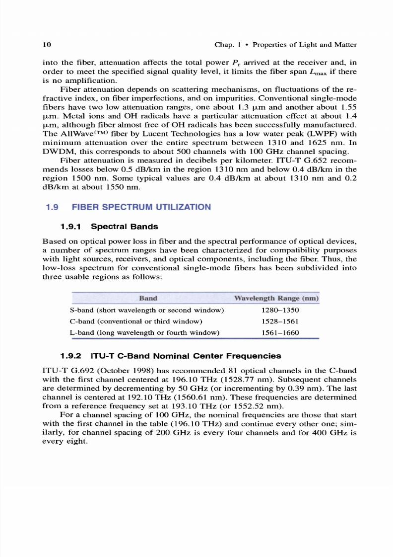
1.9.1 Spectral Bands
Based on optical power loss in fiber and the spectral performance of optical devices,a number of spectrum ranges have been characterized for compatibility purposes
with light sources , receivers, and optical components, including the fiber. Thus, the
low-loss spectrum for conventional single-mode fibers has been subdivided into
three usable regions as follows:
Band
S-band (short wavelength or second window)
C-band (conventional or third window)L-band (long wavelength or fourth window)
Wavelength Range (nm)
1280-1350
1528-15611561-1660
1.9.2 ITU T C Band Nominal Center Frequencies
ITU-T G.692 (October 1998) has recommended 81 optical channels in the C-band
with the first channel centered at 196.10 THz (1528.77 nm). Subsequent channels
are determined by decrementing by 50 GHz (or incrementing by 0.39 nm). The last
channel is centered at 192.10 THz (1560.61 nm). These frequencies are determined
from a reference frequency set at 193.10 THz (or 1552.52 nm).For a channel spacing of 100 GHz, the nominal frequencies are those that start
with the first channel in the table (196.10 THz) and continue every other one; sim
ilarly, for channel spacing of 200 GHz is every four channels and for 400 GHz is
every eight.

7/22/2019 Fault Detectability in DWDM - Toward Higher Signal Quality & System Reliability
http://slidepdf.com/reader/full/fault-detectability-in-dwdm-toward-higher-signal-quality-system-reliability 29/169
Sec. 1.11 • Spectral Broadening 11
The nominal frequency of each channel in the range 196.10-192.10 THz is cal
culated according to
F = 196.10 - ms (THz)
where m = 1,2, and s = 0.050,0.100,0.200,0.400 THz, or
F = 193.10 ± ms (THz)
where m = 0, 1, 2, and s = 0.050,0.100,0.200,0.400 THz.
1.10 NONLINEAR PHENOMENA
When light enters matter, photons and atoms interact, and under certain circum
stances, photons may be absorbed by atoms and excite them to higher energy levels.
When atoms are excited to a higher state, they do not remain stable. Photons
passing by may stimulate them to come down to their initial lower energy level by
releasing energy, photons and phonons (the acoustic quantum equivalent of light).
The behavior of dielectric molecules to optical power is like a dipole. It is the
dipole nature of a dielectric that interacts harmonically with electromagnetic waves
such as light. When the optical power is low, it results in small oscillations that ap
proximate the photon-fiber system linear behavior. However, when the optical
power is large, the oscillations are such that higher order terms (nonlinear behav
ior) become significant.
In addition to the phenomena from the photon-atom interaction, there are also
photon-atom-photon interactions that result in some complex phenomena, some of
them not well understood yet. These interactions are distinguished in forward scat
tering and in backward scattering [Raman scattering (SRS) and Brillouin (SBS)
scattering] as well as in four-wave or four-photon mixing (FWM). The direction
(forward and backward) is with respect to the direction of the excitation light.
In optical systems, nonlinear phenomena are viewed as both advantageous and
degrading:
• Advantageous, because lasers, optical amplifiers, and dispersion compensa
tion are based on them
• Degrading, because signal losses, noise, cross-talk, and pulse broadening are
caused by them
1.11 SPECTRAL BROADENING
The refractive index of many materials depends on the amplitude of the electrical
field. Thus, as the electrical field changes, so does the refractive index. However,
refractive index variations impact the transmission characteristics of the signal it
self.

7/22/2019 Fault Detectability in DWDM - Toward Higher Signal Quality & System Reliability
http://slidepdf.com/reader/full/fault-detectability-in-dwdm-toward-higher-signal-quality-system-reliability 30/169
12 Chap. 1 • Properties of Light and Matter
As an almost monochromatic light pulse travels through a fiber, its amplitude
variation causes phase change and spectral broadening. Phase variations are equiv
alent to frequency modulation or chirping. Spectral broadening appears as if onehalf of the frequency is downshifted (known as red shift and as if the other half is
upshifted (known as blue shift . Such shifts are also expected in pulses that consist
of a narrow range of wavelengths and are centered at the zero-dispersion wave
length. Below the zero-dispersion point wavelength dispersion is negative and
above it is positive. Because of this, the zero-dispersion point is avoided and the op
erating point is preferred to be in the positive or in the negative dispersion area.
1.12 SELF PHASE MODULATION
The dynamic characteristics of a propagating light pulse in a fiber result in modu
lation of its own phase, due to the Kerr effect of the fiber medium. According to
this phenomenon, known as self-phase modulation, spectral broadening may also
take place.
Specifically, if the wavelength of the pulse is below the zero-dispersion point
(known as normal dispersion regime , then spectral broadening causes temporal
broadening of the pulse as it propagates. If, on the other hand, the wavelength is
above the zero-dispersion wavelength of the fiber (the anomalous dispersion regime ,then chromatic dispersion and self-phase modulation compensate for each other,
thus reducing temporal broadening.
1.13 SELF MODULATION OR MODULATION
INSTABILITY
When a single pulse of an almost monochromatic light has a wavelength above the
zero-dispersion wavelength of the fiber (the anomalous dispersion regime), another
phenomenon occurs that degrades the width of the pulse, known as self-modulation
or modulation instability. According to this, two side-lobe pulses are symmetrically
generated at either side of the original pulse.
Modulation instability affects the signal-to-noise ratio, and it is considered a
special FWM case. Modulation instability is reduced by operating at low energy
levels and/or at wavelengths below the zero-dispersion wavelength.
1.14 EFFECTS OF TEMPERATURE ON MATTER
AND LIGHT
The properties of materials vary as temperature varies. In addition to changing its
physical properties, the optical, electrical, magnetic, and chemical properties change

7/22/2019 Fault Detectability in DWDM - Toward Higher Signal Quality & System Reliability
http://slidepdf.com/reader/full/fault-detectability-in-dwdm-toward-higher-signal-quality-system-reliability 31/169
Sec. 1.15 • Light Attributes 13
as well . As a result, the crystaline structure of matter is affected as well as its di
electric constant and the index of refraction . Clearly, in optical communications, ad
verse changes on the propagation parameters affect the optical signal and its quality, its signal-to-noise ratio, and thus the bit error rate (BER). Therefore, temperature
variations are undesirable, although there are cases where this has been used pro
ductively to control optical devices by varying the temperature and thus the refrac
tive index. In subsequent chapters we study the effect of parametric changes on the
quality of the optical signal.
1.15 LIGHT ATTRIBUTES
Light consists of many frequencies. Its power may be split, coupled, reflected, re
fracted, diffracted, absorbed, scattered, and polarized . Light interacts with matter,
and it even interacts with itself. Light is immune to radio frequency (RF) electro
magnetic interference (EMI). The attributes of light are given below:
Light Attributes
Dual nature
Consists of many A's
Propagation
Polarization
Optical power
Propagation speed
Phase
Optical channel
Comments
Electromagnetic wave and particle
Within a very wide and continuous spectrum
Under certain circumstances, its frequency may be
changed to another
Follows a straight path in free space*
Follows the bends of optical waveguides
Its speed depends on the refractive index of matter
Affected by refractive index variations
Circular, Elliptic, Linear (TEnm , TMnm )
Polarization is affected by fields
Polarization is affected by matter
Wide range (from less than microwatts to watts/
Fastest possible (in free space c - 1010 cm/s, in matter c/n
Affected by field discontinuities
Affected by material constants
A narrow band of optical frequencies is modulated
Ultrafast modulation (many gigahertz) possibleMay be contaminated by additive optical spectral noise
*Undisturbed light travels forever. In matter, it travels the shortest possible path.
Here, we consider optical power in fiber communications.

7/22/2019 Fault Detectability in DWDM - Toward Higher Signal Quality & System Reliability
http://slidepdf.com/reader/full/fault-detectability-in-dwdm-toward-higher-signal-quality-system-reliability 32/169
4
Cause
h'S interact among themselves
h's interact with matter
Each h interacts with matter
differently
X-matter-X interaction
No purely monochromatic(single-h) channel
Chap. I • Properties of Light and Matter
Effect
Interference, new wavelength generation
Range of effects (e.g., absorption, scattering, reflection,
refraction, diffraction, polarization, polarization shift)
Nonlinear effects (e.g., FWM)
Range of effects (e.g., dispersion, PMD)
Birefringence, phase shift, modulation issues, SRS, SBS,
optical fiber amplifiers (OFAs); possible wavelength
conversion
Finite number of channels within spectrum
1.16 MATERIAL ATTRIBUTES
Not all optical materials interact with light in the same manner. Materials with
specific desirable optical properties have been used to device optical compo-
Material Attributes
Refractive index n
Flat surface reflectivity R
Transparency n
Scattering
Absorption A
Polarization P
Birefringence B)
Phase shift dC{»
Ions act like dipoles
Comments
A function of molecular structure of matter
A function of optical frequency
A function of optical intensity
Determines optical propagation properties of each h
Affected by external temperature, pressure, and fields
A function of molecular/atomic structure, hand n
Affects the reflected power (also a function of angle)
Changes the polarization of incident waveChanges the phase of incident optical wave
Depends on material consistency and parameters
Mainly due to molecular matrix disorders and contaminants
Mainly due to ions in the matrix and other contaminants
Due to X-Yuneven electromagnetic (EM) fields (light-matter
interaction)
Due to nonuniform distribution of n in all directions
Due to wave property of light through matter
Exhibit eigenfrequencies
Exhibit antenna characteristics (receiver/transmitter)

7/22/2019 Fault Detectability in DWDM - Toward Higher Signal Quality & System Reliability
http://slidepdf.com/reader/full/fault-detectability-in-dwdm-toward-higher-signal-quality-system-reliability 33/169
Sec. 1.17 • Measurable Parameters 15
nents. In some cases , artificially made materials have been manufactured to
produce desirable properties. Here we examine certain key atributes of optical
materials.
Cause
Refractive index variation n
Transparency variation
Scattering
Absorption
Reflectivity
Polarization
Birefringence
Phase shift (PS)
Ions act like EM dipoles
Effect
May not be the same in all directions within matter
Affects the propagation of light
Responsible for birefringence , dispersion, and dichroism
Affects the amount of light passing through matter
Photonic power loss (attenuation)
Photonic power loss, SRS, SBS, OFA
Material surface reflects optical power
Changes polarization of incident optical wave
Changes phase of incident optical wave
Mode change: circular, elliptic, linear (TEnm , TMnm )
Affects power received
Splits light in two different rays and directions (ordinary
and extraordinary)
Optical PS may be desirable or undesirableUndesirable in transmission, desirable when it is
controlled
Interact selectively with light waves
Responsible for energy absorption or energy exchange
Change propagation characteristics (speed, phase) of A'S
Affect the refractive index
Nonlinear phenomena (SRS, SBS, FWM)
1.17 MEASURABLE PARAMETERS
Optical parameters are measured with instruments, some small and compact and
some very complex and impractical, as they are seen from a communications sys
tem point of view. In addition, some instruments are beyond conventional knowl
edge and require extensive and specialized knowledge of optics. Therefore, the
in-system optical parameter monitors for detecting degradations and faults may
require instrumentation or measuring methods that mayor may not be cost
ineffective. However, if many resources share a measuring method, then the addedcost per optical channel (OCh) may be low. In addition, when a measuring method
requires non-evasive optical monitoring then, the optical power penalty imposed by
the method can be minimal.

7/22/2019 Fault Detectability in DWDM - Toward Higher Signal Quality & System Reliability
http://slidepdf.com/reader/full/fault-detectability-in-dwdm-toward-higher-signal-quality-system-reliability 34/169
Photonic Parameters Detectability*
Center wavelength (AO) of an optical channel (nm)
Line witdth nm, or GHz)
Line spacing or channel separation GHz, or nm)
Power amplitude at AO P o, mW)
Launched optical power (P launched, mW)
Received optical power (Preceived mW)
Insertion loss L , dB)
Polarization , degree of (DOP, )
Polarization-dependent loss (PDL) (dB)
Direction of propagation (Cartesian or polar coordinates)
Speed of light v
Group velocity v g)
Propagation constant 13)
Spectrum analyzer
Spectrum analyzer
Spectrum analyzer
Filter plus photodetector
Backscattered photodetector
Filter plus photodetector
Calculate ratio PO/PI
Complex
Complex
Complex
Complex
Complex
Complex
* Complex denotes, based on current techniques, a nontriv ial optoelectronic set-up.
Parameters Due to Light
Matter Interaction CalculabilitylDetectability
Lij = - 10 10glOtj or L ij = P, - PI; t ij = input/output
(I/O) power transfer
g A = IO 10g[Pout >,,)/Pin > )], Pin < Pou t
PO/PE; indirectly (BER, cross-talk)
PB/Pp ; indirectly from IL and A A
Indirectly: eye diagram, BER , cross-talkT( A) = T + SoI2 A - AO2t
See lTD G.650 for procedure
AA = 10 10g[Pou,(A /Pin(A)], Pin > Pout
a (A) = A > )/ L; provided by manufacturer's specifications
Amplification gain (dB)
Birefringence
Extinction ratio
Attenuation (- dB)
Attenuation coefficient (dBIkm)
Insertion loss (- dB)
Pulse spreading (ps)
Group delay (ps)*
Differential group delay
(ps/km l/2)
Chromatic dispersion coefficient D(A) = SO A - AO)
(ps/nm-km)*
Polarization mode dispersion
(pslkm l12)
Phase shift < »
Polarization mode shift
Dispersion effects
Requires laboratory optical set-up
InterferometryRequires laboratory optical set-up
See pulse spreading
Note: Po and PE : optical power in the ordinary and extraordinary directions, respectively; Po and Pp :
optical power in the backward and in the forward directions, respectively.
*Relationship depends on fiber type (see ITU-T G.652, G.653, G.654 ).
tSo is the zero-dispersion slope.

7/22/2019 Fault Detectability in DWDM - Toward Higher Signal Quality & System Reliability
http://slidepdf.com/reader/full/fault-detectability-in-dwdm-toward-higher-signal-quality-system-reliability 35/169
References
R F R N S
17
[1] M. H. Freeman,Optics,
10th ed., Butterworths, London, 1990.[2] W. H. A. Fincham and M. H. Freeman, Optics, Butterworths, London, 1974.
[3] E. B. Brown, Modem Optics, Reinhold, New York, 1965.
[4] A. Kastler, Optique, 6th ed., Masson Cie, Paris, 1965.
[5] K. Nassau, The Physics and Chemistry of Color, Wiley, New York, 1983.
[6] H. A. Haus, Waves and Fields in Optoelectronics, Prentice-Hall, Englewood Cliffs, NJ,
1984.
[7] T. Wildi, Units and Conversion Charts, 2nd ed., IEEE Press, New York, 1995.
[8] R. G. Hunsperger, Integrated Optics: Theory and Technology, Springer-Verlag, New
York, 1984.
[9] L. Desmarais, Applied Electro-Optics, Prentice-Hall, Englewood Cliffs, NJ, 1999.
[10] J. Nellist, Understanding Telecommunications and Lightwave Systems, IEEE Press,
New York, 1996.
[11] J. Hecht, Understanding Fiber Optics, Prentice-Hall, Englewood Cliffs, NJ, 1999.
[12] E. B. Came, Telecommunications Primer, Prentice-Hall, Englewood Cliffs, NJ, 1995.
[13] P. S. Henry, Lightwave Primer, IEEE J. Quant. Electron., vol. QE-21, 1985, pp.
1862-1879.
[14] J. J. Refi, Optical Fibers for Optical Networking, Bell Labs. Tech. J., vol. 4, no. 1,1999, pp. 246-261.
[15] L. Kazovsky, S. Benedetto, and A. Willner, Optical Fiber Communication Systems,
Artech House, Boston, 1996.
[16] B. Mukherjee, Optical Communication Networks, McGraw-Hill, New York, 1997.
[17] J. C. Palais, Fiber Optic Communications, 3rd ed., Prentice-Hall, Englewood Cliffs, NJ,
1992.
[18] S. V.Kartalopoulos, Understanding SONETISDH and ATM: Communications Networks
for the Next Millennium, IEEE Press, New York, 1999.
[19] S. V. Kartalopoulos, Introduction to DWDM Technology: Data in a Rainbow, IEEEPress, New York, 2000.
[20] H. Toba and K. Nosu, Optical Frequency Division Multiplexing System-Review of
Key Technologies and Applications, IEICE Trans. Comm., vol. E75-B, no. 4, Apr.
1992,pp.243-255
[21] J. R. Freer, Computer Communications and Networks, IEEE Press, New York, 1996.
[22] S. R. Nagle, Optical Fiber-The Expanding Medium, Circuits Devices Mag.,
vol. 5, no. 2, 1989, pp. 36-45.
[23] R. H. Stolen, Non-Linear Properties of Optical Fibers, in Optical Fiber Telecommu
nications, S. E. Miller and G. Chynoweth, Eds., Academic, New York, 1979.[24] F. Ouellette, All-Fiber for Efficient Dispersion Compensation, Opt. Lett., vol. 16, no.
5, 1991,pp. 303-304.
[25] S. E. Miller, Coupled-Wave Theory and Waveguide Applications, Bell Syst. Tech. J.,
vol. 33, 1954, pp. 661-719.
7/22/2019 Fault Detectability in DWDM - Toward Higher Signal Quality & System Reliability
http://slidepdf.com/reader/full/fault-detectability-in-dwdm-toward-higher-signal-quality-system-reliability 36/169
8 Chap. 1 • Properties of Light and Matter
[26] A. Yariv, Coupled Mode Theory for Guided Wave Optics, IEEE J. Quant. Electron.,
vol QE-9, 1973, pp. 919-933.
[27] R. Driggers, P. Cox, and T. Edwards, An Introduction to Infrared and Electro-OpticalSystems, Artech House, Boston, 1999.
[28] N. Shibata, K. Nosu, K. Iwashita, and Y. Azuma, Transmission Limitations Due to
Fiber Nonlinearities in Optical FDM Systems, J. Selected Areas Commun., vol.
8,no. 6, 1990,pp. 1068-1077.
[29] S. V. Kartalopoulos, A Plateau of Performance? Guest Editorial, Commun.
Mag., Sept. 1992, pp. 13-14.
STANDARDS
[1] ANSI/IEEE 812-1984, Definition of Terms Relating to Fiber Optics, 1984.
[2] IEC Publication 793-2, Part 2, Optical Fibres-Part 2: Product Specifications, 1992.
[3] ITU-T Recommendation G.652, version 4, Characteristics of a Single-Mode Optical
Fiber Cable, Apr. 1997.
[4] ITU-T Recommendation G.653, version 4, Characteristics of a Dispersion-Shifted Sin
gle-Mode Optical Fiber Cable, Apr. 1997.
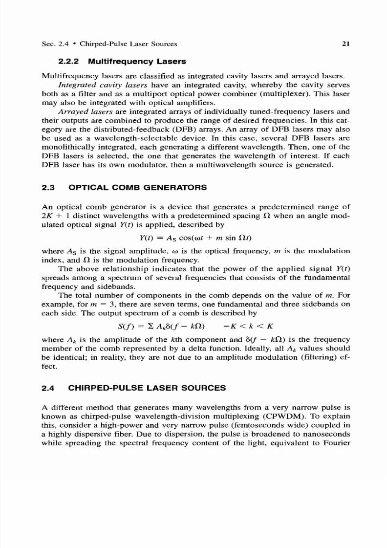
[5] ITU-T Recommendation G.654, Characteristics of a Cut-off Shifted Single-Mode Op
tical Fibre Cable, 1997.
[6] ITU-T Recommendation G.655, version 10, Characteristics of a Non-Zero DispersionShifted Single-Mode Optical Fiber Cable, Oct. 1996.
[7] ITU-T Recommendation G.662, Generic Characteristics of Optical Fiber Amplifier
Devices and Sub-Systems, July 1995.
[8] ITU-T Recommendation G.671, Transmission Characteristics of Passive Optical Com
ponents, Nov. 1996.
[9] ITU-T Recommendation G.702, Digital Hierarchy Bit Rates, 1988.
[10] ITU-T Recommendation G.821, Error Performance of an International Digital Con
nection Operating at a Bit Rate Below the Primary Rate and Forming Part of an Inte
grated Services Digital Network, Aug. 1996.[11] ITU-T Recommendation G.826, Error Performance Parameters and Objectives for In
ternational, Constant Bit Rate Digital Paths at or Above the Primary Rate, Feb. 1999.
[12] ITU-T Recommendation G.828, Error Performance Parameters and Objectives for In
ternational, Constant Bit Rate Synchronous Digital Paths, Feb. 2000.
[13] Go to http://www.itu.intlITU-T/index.html, for more information on ITU standards.

7/22/2019 Fault Detectability in DWDM - Toward Higher Signal Quality & System Reliability
http://slidepdf.com/reader/full/fault-detectability-in-dwdm-toward-higher-signal-quality-system-reliability 37/169
CHAPTER 2
OPTICAL COMPONENTS
2.1 INTRODUCTION
The four key components in optical communications systems are the monochro
matic light source, the light modulator, the optical fiber, and the photodetector or
receiver. However, the key components in DWDM optical communications systems,
in addition to the aforementioned, are filters, optical multiplexers and demultiplex
ers, optical switches, and optical amplifiers.
In optical communications, optical components should be compact, monochro
matic, or polychromatic (as required) and stable over their life span. Stability im
plies constant output power level (over time and temperature variations) and no
wavelength drifting.
2.2 LASER SOURCES
Laser stands for light amplification by stimulated emission radiation. It has been
found that some elements in gaseous state (e.g., He-Ne) and some in solid state
(e.g., ruby with 0.05 chromium) absorb electromagnetic energy (light) and remain
in a semistable high-energy excited state for a short period. This high-energy state
can then be stimulated in a controllable manner to emit light of specific wavelengths
at a variety of power levels.
This property of certain materials is used to construct a laser source. When the
material is excited, traveling photons interact with it in the electron-hole recombi
nation region whereby a cascaded and rapid process is triggered by which excitedatoms drop from their high-energy state to a low-energy state by releasing energy
in the form of light; that is, a single photon causes many. Photons are created in a
region known as the cavity where they are reflected back and forth (in phase) to
form a coherent monochromatic beam; photons traveling in other directions are
19

7/22/2019 Fault Detectability in DWDM - Toward Higher Signal Quality & System Reliability
http://slidepdf.com/reader/full/fault-detectability-in-dwdm-toward-higher-signal-quality-system-reliability 38/169
20 Chap. 2 • Optical Components
eventually lost through the walls of the cavity. As energy is pumped in, the emitted
photons are replenished, and the optical gain reaches a threshold and the lasing
process starts. The lasing property of certain organic materials in crystal phase havealso been demonstrated.
Lasers that support a single transversal mode are known as single-mode
(whether they oscillate in a single or multiple longitudinal modes) . Those that sup
port both a single transversal mode and a single longitudinal mode are known as
single-frequency lasers. I f they oscillate at several frequencies simultaneously, lon
gitudinal or transversal, then, they are called multifrequency lasers.
Lasers can be directly modulated. However, direct modulation at very high bit
rates 10-40 Gbps) has an unpleasant effect. As the drive current changes from logic
I to logic 0 and vice versa, the refractive index of the laser cavity changes dynamically (effectively changing the resonant cavity characteristics), which causes dy
namic change in wavelength, and hence opti cal chirping; that is, a form of wave
length jitter and noise. Chirping is undesirable, and to avoid it, external modulation
is used, in which case the laser emits a continuous wave (CW). However, since
lasers and modulators can be made with In+Ga+As+P, then, they can both be
monolithically integrated on an InP substrate to yield a compact device.
Wavelength and signal amplitude stability of semiconductor lasers is important
in efficient transmission. Stability depends on materials, bias voltage, and temper
ature (Figure 2.1) . Usually frequency stabilization is established using thermoelectric cooling techniques that keep the temperature stable within a fraction of a de
gree Celsius. However, this adds to the cost structure and power consumption of the
device, and efforts are made to design cooler devices.
1.0 - - . . -
0.0 ..L-_ '= - --- --- -..........J .
Relativei0.5
Intensityl
-690 - 700
As temperature rises
Spectrum shifts and
Intensity decrease
A (nm)
Figure 2.1 Spectral output depends on the absolute junction temperature.
2 2 Single-Frequency Lasers
Single-frequency lasers are tuned by controlling the refractive index. In this case,
the index of refraction in the lasing cavity is varied so that the peak transmissivity
of the intracavity filter shifts to yield the desired wavelength. Changing the refrac
tive index is equivalent to increasing the length of a free-space cavity. (Why?)
7/22/2019 Fault Detectability in DWDM - Toward Higher Signal Quality & System Reliability
http://slidepdf.com/reader/full/fault-detectability-in-dwdm-toward-higher-signal-quality-system-reliability 39/169
Sec. 2.4 • Chirped-Pulse Laser Sources
2.2.2 Multifrequency Lasers
21
Multifrequency lasers are classified as integrated cavity lasers and arrayed lasers.Integrated cavity lasers have an integrated cavity, whereby the cavity serves
both as a filter and as a multiport optical power combiner (multiplexer). This laser
may also be integrated with optical amplifiers.
Arrayed lasers are integrated arrays of individually tuned-frequency lasers and
their outputs are combined to produce the range of desired frequencies. In this cat
egory are the distributed-feedback (DFB) arrays. An array of DFB lasers may also
be used as a wavelength-selectable device. In this case, several DFB lasers are
monolithically integrated, each generating a different wavelength. Then, one of the
DFB lasers is selected, the one that generates the wavelength of interest. If eachDFB laser has its own modulator, then a multiwavelength source is generated.
2.3 OPTICAL COMB GENERATORS
An optical comb generator is a device that generates a predetermined range of
2K + 1 distinct wavelengths with a predetermined spacing l when an angle mod
ulated optical signal yet) is applied, described by
yet) = As cos(wt + m sin [}t)
where As is the signal amplitude, w is the optical frequency, m is the modulation
index, and l is the modulation frequency.
The above relationship indicates that the power of the applied signal yet)
spreads among a spectrum of several frequencies that consists of the fundamental
frequency and sidebands.
The total number of components in the comb depends on the value of m. For
example, for m = 3, there are seven terms, one fundamental and three sidebands on
each side. The output spectrum of a comb is described by
K k < K
where Ak is the amplitude of the kth component and 8(1 - kil) is the frequency
member of the comb represented by a delta function. Ideally, all A k values should
be identical; in reality, they are not due to an amplitude modulation (filtering) ef
fect.
2.4 CHIRPED-PULSE LASER SOURCES
A different method that generates many wavelengths from a very narrow pulse is
known as chirped-pulse wavelength-division multiplexing (CPWDM). To explain
this, consider a high-power and very narrow pulse (femtoseconds wide) coupled in
a highly dispersive fiber. Due to dispersion, the pulse is broadened to nanoseconds
while spreading the spectral frequency content of the light, equivalent to Fourier

7/22/2019 Fault Detectability in DWDM - Toward Higher Signal Quality & System Reliability
http://slidepdf.com/reader/full/fault-detectability-in-dwdm-toward-higher-signal-quality-system-reliability 40/169
22 Chap. 2 • Optical Components
analysis, based on which many frequency components are generated from a single
impulse; the narrower the impulse, the more the frequency content. This method is
known as chirping. Now, consider a mode-locked laser source that emits a sequence of ultrashort pulses. Thus, each pulse generates a set of pulsed frequencies
in the time-spectrum continuum, each pulse referred to as a slice. Time-division
multiplexed data (via a fast modulator) modulate the bits of every slice and thus
each frequency channel is modulated with different data.
2.5 MODULATORS
Optical modulators are components designed to control a property of light thatpasses through them. They are devices positioned in line with a CW laser source
(external modulation) or they are monolithically integrated with a laser source (di
rect modulation). The major benefit of external modulators is that they have negli
gible chirp (phase jitter), as compared with direct modulation; chirp and fiber dis
persion effects limit the transmission distance of the source detector.
As an optical (monochromatic) beam passes through a modulator, one of its
following properties changes:
• Intensity• Phase
• Frequency
• Polarization
The parameters that characterize the performance of optical modulators are as fol
lows:
• Modulation depth TJ
• Modulation format (analog/digital, linear/nonlinear)
• Percent modulation (typical in intensity modulators)
• Bandwidth
• Insertion loss
• Degree of isolation
• Power
1. For intensity modulators: In this category are the electroabsorption (EA)modulators. Electroabsorption modulators exhibit an almost logarithmic optical
power attenuation, which depends on the voltage applied to them, thus acting as on
off optical devices. They are sources of short optical pulses (and short duty cycle),
they exhibit excellent modulation depths in excess of 45 dB, and they can generate

7/22/2019 Fault Detectability in DWDM - Toward Higher Signal Quality & System Reliability
http://slidepdf.com/reader/full/fault-detectability-in-dwdm-toward-higher-signal-quality-system-reliability 41/169
Sec. 2.6 • Photodetectors 23
bit rates in excess of 40 Gbps. They are made with InGaAsP and thus are compact
and stable devices that can easily be integrated with other optical devices (e.g., DFB
lasers).a. The modulation depth is defined by Tl = 0 - l)/Io.
b. The extinction ratio is the maximum value of Tl Tlmax when the inten
sity of the transmitted beam is a minimum, lmin, and it is given by Tlmax =
Tl(/mi n) ·
2. For phase modulators the modulation depth Tl is defined similarly provided
that the intensity is related to the phase [I = I( f>)].
3. For frequency modulators an analogous figure of merit is used known as the
maximum frequency deviation Dmax, defined as Dmax = Ifm - fo lifo, where fm is
the maximum frequency shift of the carrier fo.
The degree of isolation, in decibels, represents the maximum optical change
produced by the modulator and is related to the extinction ratio [10 loge Tl)] or to
the maximum frequency deviation (10 log Dmax).
2.6 PHOTODETECTORS
Photodetectors (or photosensors) are transducers that alter one of their characteristics in a relationship relative to the amount of light energy that impinges on them.
Thus, photoresistors alter their ohmic resistance, rods and cones, neurons of the
retina of the eye alter their electrochemical response, chlorophyll in plant leaves al
ter the rate of converting CO 2 to O2 , and semiconductor photodetectors alter the
flow of electrical current or the potential difference across their two terminals.
Photodetectors with sufficiently fast response (picoseconds) that provide a
measurable output for a small amount of light, that are easily reproducible, and that
are economical are the primary candidates in high-speed optical communication ap
plications. In this category are the avalanche photodiodes (APDs) and the positiveintrinsic-negative (PIN) diodes.
Photodetectors are characterized by certain key parameters. Among them are
the spectral response, photosensitivity, quantum efficiency, dark current, forward
biased noise, noise-equivalent power, terminal capacitance, timing response (rise
time and fall time), frequency bandwidth, and cutofffrequency:
• Spectral response relates the amount of current produced with wavelength,
assuming all wavelengths are at the same level of light.
• Photosensitivity is the ratio of light energy (in watts) incident on the device
to the resulting current (in amperes).
• Quantum efficiency is the number of generated electron-holes (i.e., current)
divided by the number of photons.

7/22/2019 Fault Detectability in DWDM - Toward Higher Signal Quality & System Reliability
http://slidepdf.com/reader/full/fault-detectability-in-dwdm-toward-higher-signal-quality-system-reliability 42/169
24 Chap. 2 • Optical Components
• Dark current is the amount of current that flows through the photodiode in
the absence of any light (dark), when the diode is reverse biased. This be
comes a source of noise when the diode is reversed biased.
• Forward-biased noise is a (current) source of noise that is related to the shunt
resistance of the device. The shunt resistance is defined as the ratio voltage
(near 0 V) over the amount of current generated. This is also called shunt re
sistance noise.
• Noise-equivalent power is defined as the amount of light (of a given wave
length) that is equivalent to the noise level of the device.
• Terminal capacitance is the capacitance from the p-n junction of the diode to
the connectors of the device; it limits the response of the photodetector.
• The timing response of the photodetector is defined as the time lapsed for the
output signal to reach from 10 to 90 of its amplitude (rise time) and from
90 to 10 (fall time).
• Frequency bandwidth is defined as the frequency (or wavelength) range in
which the photodetector is sensitive.
• Cutoff frequency is the highest frequency (wavelength) to which the pho
todetector is sensitive.
2.7 FIXED OPTICAL FILTERS
The function of a filter is to recognize a narrow band of electrical frequencies from
a multiplicity and either pass it or reject it. Optical spectral filters are based on in
terference or on absorption and they are distinguished in fixed and in tunable fil
ters.
Filters are characterized by several parameters:
• Spectral width is defined as the band of frequencies that will pass through
the filter. The spectral width is characterized by an upper and by a lower fre
quency (wavelength) threshold. In addition, it is characterized by a gain curve
that is a measure of the degree of flatness over the spectral width.
• Line width or channel width is defined as the width of the frequency chan
nel. An ideal channel should be monochromatic, that is, a single wavelength.
However, this is not possible, and thus the line width is a measure of howclose to ideal a channel is, as well as an indication of the spectral content of
the channel.
• Line spacing is defined as the distance in wavelength units (nanometers) or
in frequency units (gigahertz) between two channels.

7/22/2019 Fault Detectability in DWDM - Toward Higher Signal Quality & System Reliability
http://slidepdf.com/reader/full/fault-detectability-in-dwdm-toward-higher-signal-quality-system-reliability 43/169
Sec. 2.7 • Fixed Optical Filters 25
• Finesse is an indication of how many wavelength (or frequency) channels can
simultaneously pass through the filter without severeinterference among them.
The finesse is a measure of the energy of wavelengths within the cavity relative to the energy lost per cycle. Thus, the higher the finesse, the narrower the
resonant linewidth.The Q-factorof electrical filters is equivalent to the finesse.
Cavity losses due to imperfections of mirrors (e.g., flatness) and angle of inci
dence of the light beam impact the finesse value. Usually, the finesse is dominated
by reflector losses due to power that flows in and out as a result of the semitrans
parency of the filter reflectors.
2.7.1 Fabry-Perot FilterThe Fabry-Perot filter is based on the interference of multiple reflections of a light
beam by two surfaces of a thin plate (Figure 2.2). It consists of two high-reflectance
semireflectors separated by a distance d. Multiple interference in the space layer
causes the filter output spectral characteristic to peak sharply over a narrow band of
wavelengths that are multiple of the >J spacer layer.The condition for interference
maxima for each wavelength is 2d sin 0 = ns; where n is an integer. The values
of A that satisfy the relationship A = 2dnlm determine the modes of the Fabry-Perot
filter. As an example, for m = 1 and n = 1, A = 2d; for m = 2 and n = 1, I = d.
Thus, a Fabry-Perot filter is used exclusively as a bandpass filter.
Semi
mirror 2Air or
Dielectric
Semi
mirror 1
Incident lightE O
t II> ················· ...... Outgo ing lightt ..... ......R R 2 E l ~ s t ,RR2 2E 3d
' 4.
d
Figure 2.2 Principles of the Fabry-Perot interferometer.
2.7.2 Bragg Grating Filter
The Bragg grating is an arrangement of multiple parallel semireflecting plates (Fig
ure 2.3). In this arrangement the condition for total reflection is derived in the form
of a geometric series when one calculates the sum of all reflected components atthe first mirror and assuming that all waves arrive in phase. Then, this sum yields
the condition for strong reflection or Bragg condition d = - n A B/2. The negative
sign denotes reflection and n is the order of the Bragg grating. When n = 1 (first
order), d = >J and when n = 2 (second order), d = A.

7/22/2019 Fault Detectability in DWDM - Toward Higher Signal Quality & System Reliability
http://slidepdf.com/reader/full/fault-detectability-in-dwdm-toward-higher-signal-quality-system-reliability 44/169
26 Chap. 2 • Optical Components
Incident light beam
1 + 2 +.. A N
1
Diffracted
2
wavelengths
A N
Blaze angle,8s
Figure 2.3 Principles of the diffraction grating; shown are the blaze angle and the grating period.
A fiber Bragg grating (FBG) consists of a fiber segment whose index of refraction varies periodically along its length. Fiber Bragg gratings with a variable
pitch may compensate for chromatic dispersion, known as chirped-FBGs.
A similar Bragg grating reflector is based on a stack of dielectric layers, known
as photonic lattice. The layers are quarter-wavelength thick and with different re
fractive indices. Photonic lattice reflectors have been found to reflect wavelengths,
in the spectral band it is designed for, over all possible angles of incidence, and they
do not absorb any of the incident energy, as mirror-based reflectors do.
2.7.3 Mach-Zehnder Filter
The Mach-Zehnder filter is based on the interference of two coherent monochro
matic sources that, based on the length difference and thus the phase difference of
the two paths, contribute positively or negatively. However, one should remember
that since optical channels are not purely monochromatic, the polychromatic nature
of each optical channel should be taken into account when calculating the minima
(destructive interference) and maxima (constructive interference) of light.
2.7.4 Dielectric Thin-Film Filter
Dielectric thin-film (DTF) interference filters consist of alternate layers of high re
fractive index and low refractive index, each layer being A/4 thick. Light of speci
fied Aand reflected within the layers of high index does not shift its phase, whereas
those within the low index shift by 1800• Taking into account the travel difference
(in multiples of 2 X A/4), reflected light recombines constructively at the front face,
producing a highly reflected beam with wavelengths in a narrow range. Outside this
range the wavelengths drop abruptly at the output of the filter.
The primary considerations in DTF design are as follows:
• Low passband loss
• Good channel spacing
• Low interchannel cross-talk

7/22/2019 Fault Detectability in DWDM - Toward Higher Signal Quality & System Reliability
http://slidepdf.com/reader/full/fault-detectability-in-dwdm-toward-higher-signal-quality-system-reliability 45/169
Sec. 2.8 • Tunable Optical Filters 27
The wavelength range at the output of the A./4 stack depends on the ratio of high to
low refractive index. Thus, a DTF can be used as a high-pass filter, a low-pass fil
ter, or a high-reflectance layer. Low passband loss is achieved with multilayer structures that exceed 98 reflectance. Clearly, any external influence that may alter the
parameters of a DFf will also alter the filter characteristics.
2.7.5 Quarter-Wavelength and Half-WavelengthPlates
A birefringent plate of a quarter-wavelength ( A./4) thickness and with the surfaces
parallel to the optic axis has important properties on polarized light.
If the linear-polarized light is at 45° to the fast optical axis, the polarization istransformed into circular-polarized light, and vice versa.
If the linear-polarized light is parallel to the fast or slow axis, the polarization
remains unchanged.
If the linear-polarized light is at any other angle with the optical axis, linear po
larization is transformed into elliptical polarization and vice versa.
Similar to A./4 plates, a half-wavelength plate with the surfaces parallel to the
optic axis has other important properties on polarized light.
If the linear-polarized light is at eo to the fast optical axis, the polarization remains linear but the orientation is rotated by 2eo. Thus, if the angle is 45°, the lin
ear polarization is rotated by 90°.
2.8 TUNABLE OPTICAL FILTERS
Tunable optical filters (TOFs) may be constructed with passive or active optical
components. The salient characteristic of TOFs is their ability to select the range of
filtered wavelengths. However, to be useful in optical communication systems, theymust satisfy certain requirements:
• Wide tuning range (large number of channels)
• Constant gain (over the filter spectrum)
• Narrow bandwidth
• Fast tuning
• Insensitivity to temperature (no frequency drift with temperature variations)
Each tunable filter type has its own performance characteristics. Therefore, de
pending on the application, the filter type that best matches the performance re
quirements should be used.
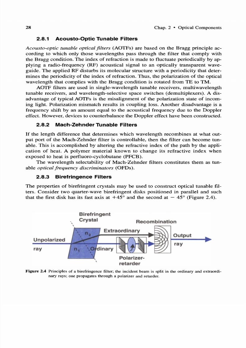
7/22/2019 Fault Detectability in DWDM - Toward Higher Signal Quality & System Reliability
http://slidepdf.com/reader/full/fault-detectability-in-dwdm-toward-higher-signal-quality-system-reliability 46/169
28 Chap. 2 • OpticalComponents
2.8.1 Acousto-Optic Tunable Filters
Acousto-optic tunable optical filters (AOTFs) are based on the Bragg principle ac
cording to which only those wavelengths pass through the filter that comply with
the Bragg condition. The index of refraction is made to fluctuate periodically by ap
plying a radio-frequency (RF) acoustical signal to an optically transparent wave
guide . The applied RF disturbs its molecular structure with a periodicity that deter
mines the periodicity of the index of refraction. Thus, the polarization of the optical
wavelength that complies with the Bragg condition is rotated from TE to TM.
AOTF filters are used in single-wavelength tunable receivers, multiwavelength
tunable receivers, and wavelength-selective space switches (demultiplexers). A dis
advantage of typical AOTFs is the misalignment of the polarization state of incoming light. Polarization mismatch results in coupling loss. Another disadvantage is a
frequency shift by an amount equal to the acoustical frequency due to the Doppler
effect. However, devices to counterbalance the Doppler effect have been constructed.
2.8.2 Mach-Zehnder Tunable Filters
If the length difference that determines which wavelength recombines at what out
put port of the Mach-Zehnder filter is controllable, then the filter can become tun
able. This is accomplished by altering the refractive index of the path by the appli
cation of heat. A polymer material known to change its refractive index whenexposed to heat is perfluoro-cyclobutane (PFCB).
The wavelength selectability of Mach-Zehnder filters constitutes them as tun
able optical frequency discriminators (OFDs) .
2.8.3 Birefringence Filters
The properties of birefringent crystals may be used to construct optical tunable fil
ters. Consider two quarter-wave birefringent disks positioned in parallel and such
that the first disk has its fast axis at +45 0 and the second at - 45 0 (Figure 2.4).
Unpolarized
ray
Birefringent
Crystal Recombination
Output
ray
Figure 2.4 Principles of a birefringence filter; the incident beam is split in the ordinary and extraordi
nary rays; one propagates through a polarizer and retarder.

7/22/2019 Fault Detectability in DWDM - Toward Higher Signal Quality & System Reliability
http://slidepdf.com/reader/full/fault-detectability-in-dwdm-toward-higher-signal-quality-system-reliability 47/169
Sec. 2.10 • Arrayed Waveguide Grating 29
Based on this, the retardation to a monochromatic beam propagating in the z
axis is summed up to zero because one disk accelerates as much as the other de
celerates. If one of the two disks is rotated by an angle 45° + p, then an acceleration or a deceleration proportional to the angle p is introduced, and a
phase-controlling mechani sm is constructed. Now, if prior to entering the first disk
a birefringent crystal splits the beam in two (the ordinary and extraordinary rays),
then each ray is controlled differently than the other, and as they recombine at the
output, a tuning mechanism or a tunable filter is constructed.
2.9 DIFFRACTION GRATINGS
A diffraction grating is an arrayed slit device that takes advantage of the diffraction
property of light and reflects light in a direction that depends on the angle of inci
dent light, the wavelength, and the grating constant (Figure 2.5). That is, a grating
diffracts wavelengths in different directions when a mixed-wavelength beam im
pinges on it. The blaze angle and the number of slits per unit length characterize a
diffraction grating.
Diffraction
grating
fibersDiffracted
E : : : : : : : : Z : : : ; : : : : : : : l : ~ ~ ~ c : : : I l . wavelengths
J1.1
1. 2
AN
Incident beam , 1.1 1 . 2 •• AN
lens
Figure 2.5 Each wavelength component of a collimated polychromatic light beam is diffracted and di
rected to a different point in space.
2.10 ARRAYED WAVEGUIDE GRATING
Arrayed waveguide grating s (AWGs) are filters of the Mach-Zehnder type. They
can be monolithically manufactured to support many optical channels (SiOz AWGs
for 128 channels and 25-GHz channel spacing as well as InP AWGs for 64 chan
nels with 50-GHz channel spacing have been reported).
7/22/2019 Fault Detectability in DWDM - Toward Higher Signal Quality & System Reliability
http://slidepdf.com/reader/full/fault-detectability-in-dwdm-toward-higher-signal-quality-system-reliability 48/169
30 Chap. 2 • Optical Components
2.11 DIRECTIONAL COUPLERS
Optical directional couplers are solid-state devices that transfer the maximum possible optical power from one or more optical device(s) to another in a selected di
rection. Power transfer may be from a light source to a fiber, from fiber to fiber,
from fiber to device (such as to a filter or a demultiplexer), and from device to fiber.
Single-mode fiber directional couplers use the evanescent property of inte
grated light guides on a substrate to couple optical power (light) of certain wave
length from one guide to another. When a voltage V is applied, optical power is
guided through the same guide, however with a phase change. When the applied
voltage V = 0, then power is transferred through the evanescent separation region
to the adjacent guide.For maximum power transfer, the proximity of two light guides, the synchro
nization of the two phase velocities, the refractive index, and the interaction (or cou
pling) length Lo are important parameters in couplers.
When the isolation between the two light guides over the length Lo is con
trolled, a controllable device may be made. Then, in addition to being a directional
coupler, such a device may be used as a power attenuator, a signal modulator, power
splitters, isolators, and an on-off switch.
2.12 OPTICAL ISOLATORS
Optical isolators are devices that transmit optical power of a band of wavelengths)
in one direction more than the other direction.
Optical isolator devices are characterized by insertion loss L, or the loss of op
tical power through it, and by isolation I, or the ratio of transmitted power in one
direction over the other direction. Ideally, it should allow transmission of all power
in one direction and no power in the other direction; that is, L = 0 and I = 0 0 .
2.13 POLARIZERS, ROTATORS, AND CIRCULATORS
Optical isolators are made with certain materials (formed in parallel plates or
prisms) that allow one polarization direction of nonpolarized light to propagate
through it. These devices are called polarizers. Birefringent materials can be used
as polarizers.
Other materials rotate the polarization direction by an angle, and they are called
rotators. Rotators are based on the Faraday effect. Rotators can be made with fibersdoped with elements or compounds that have a large Verdet constant, such as ter
bium (Tb), yttrium-iron-garnet (Y3FeS012 or YIG), and bismuth-substituted
terbium-iron-garnet (Tb3-xBixFes012 or TbBiIG). Some of them may require a
strong magnetic field, such as the YIGs.

7/22/2019 Fault Detectability in DWDM - Toward Higher Signal Quality & System Reliability
http://slidepdf.com/reader/full/fault-detectability-in-dwdm-toward-higher-signal-quality-system-reliability 49/169
Sec. 2.15 • Superprisms 31
Polarizers and rotators can be combined to form isolators . Isolators may be
viewed as two-port devices that allow unidirectional energy to flow from one ter
minal to the other. Now, if a structure is made with more than one isolator, then athree-terminal device is constructed that permits unidirectional optical energy to
flow from terminal 1 to 2, from 2 to 3, and from 3 to 1 but not in any other direc
tion. This device is known as a circulator (Figure 2.6).
Figure 2.6 Principle s of a circulator and its symbol.
2.14 OPTICAL EQUALIZERS
The wavelengths of a generated spectral range are not all of the same amplitude.
However, for proper operation at the receiving end it is necessary to have a flat out
put power spectrum. Optical equalizers monitor each wavelength channel at the out
put and selectively make amplitude adjustments to flatten the optical power of the
spectrum within a band of wavelengths.
The key desirable characteristics of optical equalizers are:
• Large wavelength range
• Low ripple of the spectrum amplitude (small peak-to-peak variation)
• High dynamic range
• Low loss
• Polarization independence
• Fast acquisition
2.15 SUPERPRISMS
When a collimated (parallel) beam of polychromatic light impinges on one of the
prism surfaces (AB), then each frequency component is refracted differently.
The output light from the prism consists of the frequency components sepa
rated from each other by a small angle. However, this angle is very small, and to

7/22/2019 Fault Detectability in DWDM - Toward Higher Signal Quality & System Reliability
http://slidepdf.com/reader/full/fault-detectability-in-dwdm-toward-higher-signal-quality-system-reliability 50/169
32 Chap. 2 • Optical Components
achieve good resolution of wavelengths, a substantial distance is required, thus mak
ing this impractical in many multiplexer/demultiplexer (Mux/Demux) applications.
This is addresed with superprisms.Superprisms are artificially made prisms the material of which forms a lattice
known as photonic crystalline. Photonic crystalline optical material is an artificial
structure with a periodic dielectric fabricated on Si. The periodicity of the crys
talline lattice is three dimensional and using nanotechnology is several tens of
nanometers (reported at 180 nm). Photonic crystalline structures act as highly dis
perssive structures that exhibit much superior angular dispersion characteristics (re
ported at 500 times higher) than conventional prisms (hence superprisms).
2.16 OPTICAL MULTIPLEXERS
AND DEMULTIPLEXERS
The main function of an optical multiplexer is to couple two or more wavelengths
into the same fiber. In general, optical multiplexers consist of a multiplicity of in
put fibers, each carrying an optical signal at different wavelength.
The demultiplexer undoes what the multiplexer has done; it separates a multi
plicity of wavelengths in a fiber and directs them to many fibers. Most optical passive demultiplexers, such as prisms and gratings, may also be used as optical mul
tiplexers.
2.17 OPTICAL CROSS-CONNECTS
Optical cross-connect devices are modeled after the many-port model. That is, N in
put ports and N output ports, and a table that defines the connectivity between in
put and one or more outputs.
All-optical cross-connect fabrics are based on at least three methods:
1. Free-space optical switching [waveguide grating routers (WGR) Mach
Zehnder interferometers]
2. Optical solid-state devices (acousto-optic and electro-optic couplers)
3. Electromechanical mirror-based devices
Other cross-connect fabrics are based on the polarization properties of liquidcrystals and other properties of materials. Optical switches based on liquid crystal
technology are relatively of limited size, up to 40 channels, but they offer high iso
lation, low insertion loss, and low cost.

7/22/2019 Fault Detectability in DWDM - Toward Higher Signal Quality & System Reliability
http://slidepdf.com/reader/full/fault-detectability-in-dwdm-toward-higher-signal-quality-system-reliability 51/169
Sec. 2.17 • Optical Cross-Connects
2.17.1 Free-Space Optical Switching
33
Among the most promising switches with many input ports to many output portsare the generalized Mach-ZehnderWGRs. In this device, a given wavelength at any
input port appears at a specified output port (Figure 2.7). Thus, an input-to-output
connectivity map is constructed, that is, a switch. This type of free-space optical
switching is also known as wavelength routing.
A1 A +•••+ AN
Input
fibers
Free space
regions
Figure 2.7 A waveguide grating router (WRG) is a generalized Mach-Zehnder interferometer.
2.17.2 Sol id-State Cross Connects
Solid-state optical cross-connect devices are 2 X 2 semiconductor directional cou
plers, taking advantage of the controllable index of refraction of ferroelectric LiNb03
crystals by the application of an external electric field. Several 2 X 2 switches can
be monolithically integrated to produce a larger switch. Although the number of
port s can be large (e.g., 128 X 128), due to cumulative losses, practical switches
have a rather limited number of ports (e.g., 16 X 16 and perhaps 32 X 32).
The material type, the controlling mechanism, and the controlled property impact the switching speed of the device as well as the number of ports of the switch.
For example, switc hes made with LiNb0 3 crystals exhibit switching speeds on the
order of nanoseconds whereas those made with SiOz on Si exhibit speeds on the or
der of under 1 ms.
Solid-state optical cross-connecting devices are characterized by a number of
parameters:
• Size of switching matrix (e.g., 2 X 2 4 X 4)
• Insertion loss (typically 1 dB)
• Isolation (typically 35 dB)
• Cross-talk (typically -40 dB)

7/22/2019 Fault Detectability in DWDM - Toward Higher Signal Quality & System Reliability
http://slidepdf.com/reader/full/fault-detectability-in-dwdm-toward-higher-signal-quality-system-reliability 52/169
34 Chap . 2 • Optical Components
• Switching speed (in the range milliseconds to nanoseconds)
• Polarization-dependent loss (fraction of a decibel)
• Spectral flatness (typically ± 1 dB)
• Operating temperature (0-70°C)
• Operating voltage (typically +5 V)
• Number of inputs and outputs (e.g., 2 inputs, 2 outputs in a 2 X 2)
• Blocking or nonblocking switching fabrics
2.17.3 Micro-Electromechanical Switches
A technology known as nanotechnology has been employed to micromachine manytiny mirrors on the same substrate. An actual microphotograph of this technology,
known as a micro-electromechanical system (MEMS), is shown Figure 2.8.
Figure 2.8 Array of micromachined mirrors, magnified 450 times. (Copyright © 1999 by Lucent Tech
nologies. Reprinted with permission.)
When a beam impinges on one of the mirrors, by reflecting the beam accord
ingly, the beam may be directed to one of many outputs, thus constructing an opti
cal switch (Figure 2.9).The MEMS technology enables the integration of an N X N mirror matrix,
where N can be potentially higher than 1000. However, the precision of tilting the
mirrors and the time required to tilt a large quantity of them at their desirable po
sition are very critical. Minor deviations in angle position may increase optical sig-

7/22/2019 Fault Detectability in DWDM - Toward Higher Signal Quality & System Reliability
http://slidepdf.com/reader/full/fault-detectability-in-dwdm-toward-higher-signal-quality-system-reliability 53/169
Sec. 2.17 • Optical Cross-Connects 35
I f,
r - - - - - - - - - - - - - - - - - - - - - - - - -I A X MEM iI t ' I
I rna r1X Collimators I Fibers J ............... I / .....
nput
mirror
Outputmirror
0 .00
0 0 0 00 0 00 0 0 I
I Ij
....... I
I Plane ii Mirror I
A 4X4 MEMS matrix
Figure 2.9 MEMS in a matrix configuration comprising an n X n connectivity matrix.
nalloss (due to beam misalignment) and increase cross-talk. Moreover, as a mirror
changes position, the reflected light beam traverses the optical field of other output
fibers. Therefore, caution should be taken so that the reflected beam is not coupled
to these traversed output fibers and thus contribute to bit error rate. Current designs
have minimized the coupled optical power in traversed output fibers.
2.17.4 Switching SpeedsCurrently, the speed of optical switching devices depends on the materials used to
make the switch, the principle on which the switch operates, and the technology.
Although speed is an important parameter, there are many more parameters that one
should consider in the selection of the switch type, such as optical loss, dispersion,
reliability, stability, switching-matrix size, external voltages (if any), temperature
dependence, physical size, and cost. Switching speeds vary from seconds to nanosec
onds:
Technology Switching Speed
Thermo-optic switching ms
Acousto-optic switching ms
Electro-optic ceramic-compound switching jLs
MEMS switching jLs
SiOz on Si planar ms-us
LiNb03 switching ns
Nonlinear electro-optic polymer APII devices ps (in experimental phase)
(amino-phenylene-isophorone-isoxazolone)

7/22/2019 Fault Detectability in DWDM - Toward Higher Signal Quality & System Reliability
http://slidepdf.com/reader/full/fault-detectability-in-dwdm-toward-higher-signal-quality-system-reliability 54/169
36
2.18 OPTICAL ADD-DROP MULTIPLEXERS
Chap. 2 • Optical Components
The optical add-drop multiplexer (OADM) is a DWDM function. It selectively removes (drops) a wavelength from a multiplicity of wavelengths in a fiber and thus
removes traffic on this channel. Then, in the same direction of data flow it adds the
same wavelength but with different data content.
OADMs are classified in fixed wavelength and in dynamically wavelength se
lectable OADMs. Figure 2.10 illustrates an OADM with a 2 X 2 LiNb03 or an ar
ray of micromirrors, and Figure 2.11 an OADM with a grating. Other technologies
may also be used. The type of technology deployed in an OADM depends on the
number of wavelengths in WDM, the number of wavelengths dropped and added
(typically one or very few), the network level (e.g., access, metro , transport shorthaul or long haul), and cost.
Opt. 2X2 switch
Optical Al AIDemultiplexer
Drop-Add wavelength, Al
Opti calMultip lexer
Figure 2.10 Principles of an optical drop-firstlthen-add multiplexer using an optical 2 X 2 switch.
2.19 OPTICAL AMPLIFIERS
Optical amplifiers (OAs) are key devices that reconstitute the attenuated optical sig
nal and thus expand the effective fiber span between two points, the data source and
the destination .
Optical amplifiers are devices based on conventional laser principles. They re
ceive one or more optical signals, each at a center frequency, and simultaneously
they amplify all wavelengths . This, as compared with regenerators, is a significant
advantage in multiwavelength (WDM) fiber systems, since one device replacesmany.
There are two types of OAs, the semiconductor laser-type optical amplifiers
(SOA) and the doped fiber-type amplifier (EDFA for doped with erbium and PDFA
for doped with praseodymium).

7/22/2019 Fault Detectability in DWDM - Toward Higher Signal Quality & System Reliability
http://slidepdf.com/reader/full/fault-detectability-in-dwdm-toward-higher-signal-quality-system-reliability 55/169
Sec. 2.19 • Optical Amplifiers 37
Channel 1
ChannelN--- '1iiI_ _ ...
~ _ C h a n n e I
r···· ······································ ······· ······································ ······l
=Laser Diode • =Pho todetec to r ... . . .. . ..... ...... . . ... ... . ............ .. ..:
Channel 1
Figure 2.11 Principles of an optical drop-first/then-add multiplexer using a fiber grating.
There are also other amplifying devices that depend on the nonlinear proper
ties of optical materials, such as the Raman.
Optical amplifiers require electrical or optical energy to excite (pump up) the
state of electron-hole pairs. Energy is typically provided by injecting electrical cur
rent (in SOA) or optical light in the ultraviolet (UV) range (in EDFA).
Amplifiers are characterized by gain, bandwidth, gain over the bandwidth,
maximum output power, dynamic range, cross-talk, noise figure, output saturation
power, and physical size. The output saturation power is defined as the output power
level at which the amplifier's gain has dropped by 3 dB.
Some key characteristics of optical amplifiers are gain, gain efficiency, gain
bandwidth, gain saturation, noise, and polarization sensitivity :
• Gain is the ratio of output power to input power (measured in decibels).
• Gain efficiency is the gain as a function of input power (decibels per milli
watt).
• Bandwidth is a function of frequency, and as such gain bandwidth is the
range of frequencies over which the amplifier is effective .
• Gain saturation is the maximum output power of the amplifier, beyond which
it cannot increase despite the input power increase.
• Noise is an inherent characteristic of amplifiers. In optical amplifiers, noise
is due to spontaneous light emission of excited ions.
• Polarization sensitivity is the gain dependence of optical amplifiers on the
polarization of the signal.
In optical communications networks, there are two distinct amplification meth
ods: the regenerator and the optical amplifier.
2.19.1 SOAs
The most important advantage of SOAs is that they are made with InGaAsP and
thus are small and compact and may be integrated with other semiconductor and
optical components. However, in contrast to EDFAs, SOAs have a high noise fig-

7/22/2019 Fault Detectability in DWDM - Toward Higher Signal Quality & System Reliability
http://slidepdf.com/reader/full/fault-detectability-in-dwdm-toward-higher-signal-quality-system-reliability 56/169
38 Chap. 2 • Optical Components
ure (more than 6 dB over 50 nm) and a high cross-talk level due to nonlinear phe
nomena (four-wave mixing). Nevertheless, SOAs are solid-state compact devices
that can also be used as wavelength converters and regenerators and in optical signal processing applications.
2.19.2 Rare-Earth Doped Fiber Amplifiers
Fiber-optic amplifiers (FOAs) in DWDM systems are heavily doped with rare-earth
elements. The attractiveness of rare-earth elements is that they fluoresce in the spec
trum of minimum loss (or absorption) of conventional silica fiber. For example,
Nd3+ and Er3
+ emit in the range of 1.3 and 1.5 J.Lm, respectively.
Based on this, one of the most successful doped fibers is the EDFA. The erbium ions may be excited by a number of optical frequencies: 514,532,667, 800,
980, and 1480 nm. These frequencies excite erbium ions to higher energy levels
from where they drop to one of four intermediate metastable levels radiating
phonons (the acoustical quantum equivalent of a photon).
Those in the lowest metastable level finally drop spontaneously after about 10 ms
(known as spontaneous lifetime) to the initial (ground) level, emitting photons at a
wavelength in the range of 1550 nm (i.e., the C-band), unless a photon (in the 1550
nm range) passes by to stimulate photon emission. The spontaneous lifetime adds to
the noise content of the optical signal, known as amplifier spontaneous emission (ASE).
An EDFA amplifier consists of one or two excitation lasers (known as the
pump), a coupling device, an erbium-doped fiber, and two isolators, one isolator per
EDFA end. The two most convenient excitation wavelengths are 980 and 1480 nm
at an output optical power from under 100 mW to about 250 mW. Pump lasers are
specifically designed for EDFA applications.
PDFAs have a high gain -30 dB) and a high saturation power (20 dBm) and
are suitable in the region 1280-1340 nm that EDFAs are not. However, PDFAs re
quire a nonsilica fiber (fluoride) that is not very common, and they require a high
power (up to 300-mW) pump laser at 1017 nm (not the popular 980 or 1480 nm).
An alternative to this is fibers that contain elements such as gallium and lanthanum(gallium-lanthanum-sulfide and gallium-lanthanum-iodine).
Designing with EDFAs, several issues should be addressed:
1. The first issue is flat gain. EDFAs do not amplify all wavelengths through
them the same; thus, the gain is not exactly flat.
2. The second issue is pump power sharing. The pump power is shared by all
wavelengths. Thus, the more wavelengths, the less power per wavelength.
However, as wavelengths may be dropped and not added, or some wavelengths are lost due to failures, EDFAs amplify fewer wavelengths more.
These two issues are addressed by properly engineering the WDM system and
by dynamic gain control.

7/22/2019 Fault Detectability in DWDM - Toward Higher Signal Quality & System Reliability
http://slidepdf.com/reader/full/fault-detectability-in-dwdm-toward-higher-signal-quality-system-reliability 57/169
Sec. 2.20 • Classification of Optical Fiber Amplifiers 39
3. The third issue is not as simple and is addressed differently. When engineer
ing a fiber-optic path, it should be remembered that optical noise sources are
cumulative and that the ASE of EDFAs introduces noise that degrades thesignal to noise ratio (SIN). Although a strong optical signal launched into the
fiber could overcome this, near the zero-dispersion wavelength region four
wave mixing would become dominant and it would degrade the SIN ratio.
2.19.3 Raman Amplifiers
Raman amplifiers are nondoped fiber amplifiers that employ high-power pump
lasers to take advantage of the nonlinearity stimulated Raman scattering (SRS)
properties of the fiber. Raman amplifiers have their pump near the receiver and thepump light travels in the opposite direction toward the source. Thus, the pump is
strongest at the receiver and weakest at the source. This has an important advan
tage, the pump power is found where mostly needed (at remote distances from the
source) and less needed (in the vicinity of the source). Consequently, the signal is
amplified where it is the weakest and less where it is the strongest. In addition, four
wave mixing effects are thus minimized.
In a different configuration, there may be two pumps, one at the transmitting
side and one at the receiving side, with each pump at different wavelengths (to
achieve simultaneous C- and L-band amplification). However, this arrangement isstill experimental, and certain nonlinearity issues (FWM, polarization), signal-pump
interactions, increased optical signal-to-noise ratio (OSNR), and Rayleigh reflection
(which may induce a lasing effect) need to be resolved.
The most important feature of Raman amplifiers is that they are nonresonant
and have a wide bandwidth range that can extend over the complete useful spec
trum from 1300 to 1600+ nm (i.e., 500 optical channels at 100-GHz spacing) with
no restriction to gain bandwidth. This enables a multi-terabit transmission technol
ogy, also referred to as Raman supercontinuum. On the negative side, Raman am
plifiers require very long fibers (on the order of several kilometers) and pump laserswith high optical power -1 W), and thus thermal management issues as well as
safety issues become nontrivial.
2.20 CLASSIFICATION OF OPTICALFIBER AMPLIFIERS
The OFAs are classified, similar to electronic and wireless systems, as power am
plifiers, preamplifiers, and line amplifiers:
• A power amplifier is capable of increasing the optical power of the modu
lated photonic signal at the source. It is placed right after the source, and thus
it may be integrated with it. It receives a large signal (from the laser source)

7/22/2019 Fault Detectability in DWDM - Toward Higher Signal Quality & System Reliability
http://slidepdf.com/reader/full/fault-detectability-in-dwdm-toward-higher-signal-quality-system-reliability 58/169
40 Chap. 2 • Optical Components
with a large signal-to-noise ratio and it boosts its power to levels about -10
dBm or higher.
• A preamplifier is characterized by very low noise and large gain to increase
a highly attenuated signal to a level that can be detected reliably by an opti
cal detector. A preamplifier is placed directly before the detector and may be
integrated with it.
• A line amplifier is characterized by large gain and low noise to amplify an
already attenuated signal so that it can travel an additional length of fiber.
The significance of these classifications impacts the pump power level and overall
cost of application of the amplifier as well as safety.
2.21 WAVELENGTH CONVERTERS
Wavelength conversion enables optical channels to be relocated, adding to the flex
ibility and efficiency of multiwavelength systems. Wavelength conversion may be
achieved by employing the nonlinearity properties of certain heterojunction semi
conductors.
Semiconductor optical amplifiers (SOAs) are also used as wavelengthconverting devices. Their basic structure consists of an active layer (erbium-doped
waveguide) sandwiched between a p-Iayer InP and an n-Iayer InP.
Currently, various methods have been explored based on cross-gain modula
tion, four-wave mixing, dispersion-shifted fiber, and other interferometric tech
niques.
REFERENCES
[1] S. V. Kartalopoulos, Introduction to DWDM Technology: Data in a Rainbow, IEEEPress, New York, 2000.
[2] C. A. Brackett, Dense Wavelength Division Multiplexing Networks: Principles and
Applications, IEEE JSAC, vol. 8, no. 6, 1990, pp. 948-964.
[3] K. Nosu, Optical FDM Network Technologies, Artech House, Boston, 1997.
[4] R. G. Hunsperger, Ed., PhotonicDevices and Systems, Marcel Dekker, New York,
1994.
[5] R. G. Hunsperger, Integrated Optics: Theory and Technology, Springer-Verlag, New
York, 1984.
[6] H. Toba and K. Nosu, Optical Frequency Division Multiplexing System-Review ofKey Technologies and Applications, IEICE Trans. Commun., vol. E75-B, no. 4, 1992,
pp. 243-255.
[7] S. V. Kartalopoulos, Understanding SONETISDH and ATM: Communications Net
works for the Next Millennium, IEEE Press, New York, 1999.

7/22/2019 Fault Detectability in DWDM - Toward Higher Signal Quality & System Reliability
http://slidepdf.com/reader/full/fault-detectability-in-dwdm-toward-higher-signal-quality-system-reliability 59/169
References 4
[8] L. Desmarais, Applied Electro-Optics, Prentice-Hall, Englewood Cliffs, NJ, 1999.
[9] B. Mukherjee, Optical Communication Networks, McGraw-Hill, New York, 1997.
[10] J. C. Palais, Fiber Optic Communications, 3rd ed., Prentice-Hall, Englewood Cliffs,NJ, 1992.
[11] R. Ramaswami and K. N. Sivarajan, Optical Networks, Morgan Kaufmann, San Fran-
cisco, CA, 1998.
[12] M. H. Freeman, Optics, 10th ed., Butterworths, London, 1990.
[13] K. Nassau, The Physics and Chemistry of Color,Wiley, New York, 1983.
[14] T. Wildi, Units and Conversion Charts, 2nd ed., IEEE Press, New York, 1995.
[15] A. J. Lowery, Computer-Aided Photonics Design, IEEE Spectrum, vol. 34, no. 4,
1997, pp. 26-31.
[16] M. Cvijetic, Coherent and Nonlinear Lightwave Communications, Artech House,
Boston, 1996.
[17] P. S. Henry, Lightwave Primer, IEEE J. Quant. Electron., vol. QE-21, 1985, pp.
1862-1879.
[18] R. Marz, Integrated Optics: Design and Modeling, Artech House, Boston, 1995.
[19] J. Hecht, Understanding Fiber Optics, Prentice-Hall, Englewood Cliffs, NJ, 1999.
[20] S. V. Kartalopoulos, A Plateau of Performance? Guest Editorial, IEEE Commun.
Mag., Sept. 1992, pp. 13-14.
[21] J. Nellist, Understanding Telecommunications and Lightwave Systems, IEEE Press,New York, 1996.
[22] R. Driggers, P. Cox, and T. Edwards, An Introduction to Infrared and Electro-Optical
Systems, Artech House, Boston, 1999.
[23] L. G. Kazovsky, Optical Signal Processing for Lightwave Communications Net
works, IEEE JSAC, vol. 8, no. 6, 1990, pp. 973-982.
[24] N. Shibata, K. Nosu, K. Iwashita, and Y. Azuma, Transmission Limitations Due to
Fiber Nonlinearities in Optical FDM Systems, IEEE J. Selected Areas Commun., vol.
8,no. 6. 1990,pp. 1068-1077.
[25] S. E. Miller, Coupled-Wave Theory andWaveguide Applications, Bell Syst. Tech. J.,vol. 33, 1954, pp. 661-719.
[26] A. Yariv, Coupled Mode Theory for Guided Wave Optics, IEEE J. Quant. Electron.,
vol QE-9, 1973, pp. 919-933.
[27] T. K. Findakly, Glass Waveguides by Ion Exchange: A Review, Opt. Eng., vol. 24,
1985, pp. 244-255.
[28] J. R. Thompson and R. Roy, Multiple Four-Wave Mixing Process in an Optical
Fiber, Opt. Lett., vol. 16, no. 8, 1991, pp. 557-559.
[29] K. Inoue, Experimental Study on Channel Crosstalk Due to Fiber Four-Wave Mixing
Around the Zero-DispersionWavelength, IEEE J. Lighwave Technol., vol. LT-12, no.6, 1994,pp. 1023-1028.
[30] K. Inoue, Suppression of Fiber Four-WaveMixing inMultichannel Transmission Us
ing Birefringent Elements, IEICE Trans. Commun., vol. E76-B, no. 9, 1993, pp.
1219-1221.

7/22/2019 Fault Detectability in DWDM - Toward Higher Signal Quality & System Reliability
http://slidepdf.com/reader/full/fault-detectability-in-dwdm-toward-higher-signal-quality-system-reliability 60/169
42 Chap. 2 • Optical Components
[31] K. Inoue, Four-Wave Mixing in an Optical Fiber in the Zero-Dispersion Wavelength
Region, IEEE J. Lighwave Technol., vol. LT-I0, no. 11, 1992, pp. 1553-1563.
[32] N. Shibata, K. Nosu, K. Iwashita, and Y. Azuma, Transmission Limitations Due toFiber Nonlinearities in Optical FDM Systems, IEEE J. Selected Areas Commun., vol.
8,no. 6. 1990,pp. 1068-1077.
[33] J. Hecht, The Laser Guidebook, 2nd ed., Tab Books, Blue Ridge Summit, PA, 1992.
[34] J. LaCourse, Laser Primer for Fiber-Optics Users, IEEE Circuits Devices Mag., vol.
8, no. 2, 1992,pp. 27-32.
[35] M. Zirngibl, Multifrequency Lasers and Applications in WDM Networks, IEEE
Commun. Mag., vol. 36, no. 12, 1998, pp. 39-41.
[36] U. Koren et aI., Wavelength Division Multiplexing Light Sources with Integrated
Quantum Well Tunable Lasers and Optical Amplification, Appl. Phys. Lett., vol. 54,1989, pp. 2056-2058.
[37] M. J. Adams, Theory of Twin-Guide Fabry-Perot Laser Amplifiers, lEE Proc., vol.
136, no. 5, 1989,pp. 287-292.
[38] K. S. Giboney, L.A. Aronson, and B. E. Lemoff, The Ideal Light Source for Datanets,
IEEE Spectrum, vol. 35, no. 2, 1998, pp. 43-53.
[39] K. Kobayashi and I. Mito, Single Frequency and Tunable Laser Diodes, J. Light
wave Techno/., vol 6. 1988, pp. 1623-1633.
[40] M-C. Amann and W. Thulke, Continuously Tunable Laser Diodes: Longitudinal ver
sus Transverse Tuning Scheme, IEEE JSAC, vol. 8, no. 6,1990, pp. 1169-1177.[41] L. A. Coldren and S. W. Corzine, Continuously Tunable Single Frequency Semicon
ductor Lasers, IEEE J. Quant. Electron., vol. QE-23, 1987, pp. 903-908.
[42] M. Okuda and K. Onaka, Tunability of Distributed Bragg Reflector Laser by Modu
lating Refractive Index in Corrugated Waveguide, Jpn. J. Appl. Phys., vol. 16, 1977,
pp. 1501-1502.
[43] Y. Kotaki, M. Matsuda, H. Ishikawa, and H. Imai, Tunable DBR Laser with Wide
Tuning Range, Electron. Lett., vol. 24, 1988, pp. 503-505.
[44] S. Adachi, Refractive Indices of III-IV Compounds: Key Properties of InGaAsP Rel
evant to Device Design, J. Appl. Phys., vol. 53, 1982, pp. 5863-5869.[45] J. G. Eden, Photochemical Processing of Semiconductors: New Applications for Vis
ible and Ultraviolet Lasers, IEEE Circuits Devices Mag., vol. 2, no. 1, 1986, pp.
18-24.
[46] A. Yariv, Quantum Well Semiconductor Lasers Are Taking Over, IEEE Circuits De
vices Mag., vol. 5, no. 6, 1989, pp. 25-28.
[47] J. LaCourse, Laser Primer for Fiber-Optics Users, IEEE Circuits Devices Mag., vol.
8,no. 2, 1992,pp. 27-32.
[48] D. Botez and L. J. Mawst, Phase-Locked Laser Arrays Revisited, IEEE Circuits De
vices Mag., vol. 12, no. 11, 1996, pp. 25-32.
[49] Z. V. Nesterova and I. V. Aleksaandrov, Optical-Fiber Sources of Coherent Light,
Sov. J. Opt. Technol., vol 54, no. 3, 1987, pp. 183-190.
[50] N. K. Dutta, III-V Device Technologies for Lightwave Applications, AT T Tech. J.,
vol. 68, no. 1, 1989, pp. 5-18.

7/22/2019 Fault Detectability in DWDM - Toward Higher Signal Quality & System Reliability
http://slidepdf.com/reader/full/fault-detectability-in-dwdm-toward-higher-signal-quality-system-reliability 61/169
References 43
[51] G. Coquin, K. W. Cheung, and M. Choy, Single- and Multiple-Wavelength Operation
of Acousto-Optically Tuned Lasers at 1.3 Microns, Proc. 11th IEEE Int. Semicon
ductor Laser Conf., Boston, 1988, pp. 130-131.[52] R. C. Alfemess, Waveguide Electro-Optic Modulators, IEEE Trans. Microwave The
ory Techn., vol. MTT-30, 1982, pp. 1121-1137.
[53] D. Nesset, T. Kelly, and D. Marcenac, All-Optical Wavelength Conversion Using
SOA Nonlinearities, IEEE Commun. Mag., vol. 36, no. 12, 1998, pp. 56-61.
[54] S. D. Personick, Receiver Design for Digital Fiber Optic Communication Systems,
I Bell Syst. Tech. J., vol. 52, no. 6, 1973, pp. 843-874.
[55] S. D. Personick, Receiver Design for Digital Fiber Optic Communication Systems,
II Bell Syst. Tech. J., vol. 52, no. 6, 1973, pp. 875-886.
[56] F. Tong, Multiwavelength Receivers for WDM Systems, IEEE Commun. Mag., vol.36, no. 12, 1998,pp. 42-49.
[57] K. Inoue, Experimental Study on Channel Crosstalk Due to Fiber Four-Wave Mixing
around the Zero-Dispersion Wavelength, IEEE J. Lighwave Technol., vol. LT-12, no.
6, 1994,pp. 1023-1028.
[58] K.-W. Cheung, Acoustooptic Tunable Filters in Narrowband WDM Networks: Sys
tem Issues and Network Applications, IEEE JSAC, vol. 8, no. 6, 1990, pp. 1015-1025.
[59] D. A. Smith, J. E. Baran, J. J. Johnson, and K.-W. Cheung, Integrated-Optic Acousti
cally-Tunable Filters for WDM Networks, IEEE lSAC, vol. 8, no. 6, 1990, pp.
1151-1159.
[60] S. R. Mallison, Wavelength-Selective Filters for Single-Mode Fiber WDM Systems
Using Fabry-Perot Interferometers, Appl. Opt., vol 26, 1987, pp. 430-436.
[61] N. Takato et aI., Silica-Based Integrated Optic Mach-Zehnder Multi/Demultiplexer
Family with Channel Spacing of 0.01-250 nm, IEEE JSAC, vol. 8, no. 6, 1990, pp.
1120-1127.
[62] W. Warzanskyj, F. Heisman, and R. C. Alfemess, Polarization-Independent Electro
Acoustically Tunable Narrow-Band Wavelength Filter, Appl. Phys. Lett., vol. 56,
1990, pp. 2009-2011.
[63] J. Frangen et aI., Integrated Optical, Acoustically-Tunable Wavelength Filter, Proc.
6th European Conf. Integrated Opt., Paris, SPIE, 1989, post-deadline paper.
[64] F. Heismann, L. Buhl, and R. C. Alfemess, Electrooptically Tunable Narrowband
Ti:LiNb03 Wavelength Filter, Electron. Lett., vol. 23, 1987, pp. 572-573.
[65] N. Goto and Y. Miyazaki, Integrated Optical Multi-/Demultiplexer Using Acous
tooptic Effect for Multiwavelength Optical Communications, IEEE JSAC, vol. 8, no.
6, 1990, pp. 1160-1168.
[66] R. M. Measures, A. T. Alavie, M. LeBlanc, S. Huang, M. Ohn, R. Masskant, and
D. Graham, Controlled Grating Chirp for Variable Optical Dispersion Compensa
tion, Proceedings, 13th Annual Conference on European Fiber Optic Communica
tions and Networks, Brighton, England, 1995, pp. 38-41.[67] G. D. Boyd and F. Heismann, Tunable Acoustooptic Reflection Filters in LiNb03
without a Doppler Shift, J. Lightwave Technol., vol. 7, 1989, pp. 625-631.
[68] D. Sadot and E. Boimovich, Tunable Optical Filters for Dense WDM Networks,
IEEE Commun. Mag., vol. 36, no. 12, 1998, pp. 50-55.

7/22/2019 Fault Detectability in DWDM - Toward Higher Signal Quality & System Reliability
http://slidepdf.com/reader/full/fault-detectability-in-dwdm-toward-higher-signal-quality-system-reliability 62/169
44 Chap. 2 • Optical Components
[69] H. Kobrinski and K. W. Cheung, Wavelength-Tunable Optical Filters: Applications
and Technologies, IEEE Commun. Mag., vol. 27, 1989, pp. 53-63.
[70] C. M. Ragdale, D. Reid, D. J. Robbins, and J. Buus, Narrowband Fiber Grating Filters, IEEE JSAC, vol. 8, no. 6, 1990, pp. 1146-1150.
[71] J. Stone and D. Marcuse, Ultrahigh Finesse Fiber Fabry-Perot Interferometers,
J. Lightwave Technol., vol. LT-4, no. 4, 1986, pp. 382-385.
[72] A. A. M. Saleh and J. Stone, Two-Stage Fabry-Perot Filters as Demultiplexers in Op
tical FDMA LAN's, J. Lightwave Techno/., vol. LT-7, 1989, pp. 323-330.
[73] S. R. Mallinson, Wavelength Selective Filters for Single-Mode Fiber WDM Systems
Using Fabry-Perot Interferometers, App/. Opt., vol. 26, 1987, pp. 430--436.
[74] G. Hernandez, Fabry-Perot Interferometers, Cambridge University Press, Cambridge,
1986.[75] F. J. Leonberger, Applications of Guided-Wave Interferometers, Laser Focus, 1982,
pp. 125-129.
[76] H. Van de Stadt and J. M. Muller, Multimirror Fabry-Perot Interferometers, J. Opt.
Soc. Am. A, vol. 2, 1985, pp. 1363-1370.
[77] P.A. Humblet and W. M. Hamdy, Crosstalk Analysis and Filter Optimization of Sin
gle- and Double-Cavity Fabry-Perot Filters, IEEE JSAC, vol. 8, no. 6, 1990, pp.
1095-1107.
[78] H. Takahashi et aI., Arrayed-Waveguide Grating for Wavelength Division Multiplex
inglDemultiplexing with Nanometer Resolution, Electron. Lett., vol. 26, 1990, pp.
87-88.
[79] J. Minowa and Y. Fujii, Dielectric Multilayer Thin Film Filters for WDM Transmis
sion, IEEE J. Lightwave Technol., vol. 1, no. 1, 1983, pp. 116-121.
[80] W. K. Chen, Passive and Active Filters, Wiley, New York, 1986.
[81] H. Kobrinski and K-W. Cheung, Wavelength-Tunable Optical Filters: Applications
and Technologies, IEEE Commun. Mag., Oct. 1989, pp. 53-63.
[82] S. Kawakami, Light Propagation along Periodic Metal-Dielectric Layers, Appl. Opt.,
vol. 22, 1983, p. 2426.
[83] J. W. Evans, The Birefringent Filter, J. Opt. Soc. Am., vol. 39, 1949, p. 229.
[84] H. Van de Stadt and J. M. Muller, Multimirror Fabry-Perot Interferometers , J. Opt.
Soc. Am. A, vol. 2, 1985, pp. 1363-1370.
[85] R. J. von Gutfeld, Laser-Enhanced Plating and Etching for Microelectronic Applica
tions, IEEE Circuits Devices Mag., vol. 2, no. 1, 1986, pp. 57-60.
[86] J. Bokor, A. R. Neureuther, and W. G. Oldham, Advanced Lithography for ULSI,
IEEE Circuits Devices Mag., vol. 12, no. 1, 1996, pp. 11-15.
[87] J. J. Refi, Optical Fibers for Optical Networking, Bell Labs Tech. J., vol. 4, no. 1,
1999, pp. 246-261.
[88] W. D. Johnston, Jr., M. A. DiGiuseppe, and D. P. Wilt, Liquid and Vapor Phase
Growth of III-V Materials for Photonic Devices, AT T Tech. J., vol. 68, no. 1, 1989,
pp.53-63.
[89] W. G. Dautremont-Smith, R. J. McCoy, and R. H. Burton, Fabrication Technologies
for III-V Compound Semiconductor Photonic and Electronic Devices, AT T Tech.
J. vol. 68, no. 1, 1989, pp. 64-82.

7/22/2019 Fault Detectability in DWDM - Toward Higher Signal Quality & System Reliability
http://slidepdf.com/reader/full/fault-detectability-in-dwdm-toward-higher-signal-quality-system-reliability 63/169
References 45
[90] N. K. Dutta, III-V Device Technologies for Lightwave Applications, AT T Tech. J.
vol. 68, no. 1, 1989, pp. 5-18.
[91] S. Adachi, Refractive Indices of III-IV Compounds: Key Properties of InGaAsP Relevant to Device Design, J. Appl. Phys., vol. 53, 1982, pp. 5863-5869.
[92] T. Komukai, et aI., Upconversion Pumped Thulium-Doped Fluoride Fiber Amplifier
and Laser Operating at 1.47 IJ-m, IEEE Quant. Electron., vol. 31,1995, pp. 1880-1889.
[93] R. Driggers, P. Cox, and T. Edwards, An Introduction to Infrared and Electro-Optical
Systems, Artech House, Boston, 1999.
[94] G. Eisenstein, Semiconductor Optical Amplifiers, IEEE Circuits Devices Mag., vol.
5,no.4, 1989,pp. 25-30.
[95] D. Nesset, T. Kelly, and D. Marcenac, All-Optical Wavelength Conversion Using
SOA Nonlinearities, IEEE Commun. Mag., vol. 36, no. 12, 1998, pp. 56-61.[96] S. Sudo, Ed., Optical Fiber Amplifiers: Materials, Devices, and Applications, Artech
House, Boston, 1997.
[97] R. J. Mears, L. Reekie, I. M. Jauncey, and D. N. Payne, Low-Noise Erbium-Doped
Fiber Amplifier Operating at 1.54 IJ-m, Electron. Lett., vol. 23, no. 19, 1987, pp.
1026-1028.
[98] E. Desurvire, J. R. Simpson, and P. C. Becker, High-Gain Erbium-Doped Traveling
Wave Fiber Amplifiers, Opt. Lett., vol. 12, no. 11, 1987, pp. 888-890.
[99] Y. Sun, A. K. Srivastava, J. Zhou, and J. W. Sulhoff, Optical Fiber Amplifiers for
WDM Optical Networks, Bell Labs Tech. J. vol. 4, no. 1, 1999, pp. 187-206.[100] O. Ishida and H. Toba, A 1.55-mm Lightwave Frequency Synthesizer, IEICE Trans.
Commun., vol. E75-B, no. 4, 1992, pp. 275-280.
[101] K. Vilhelmsson, Simultaneous Forward and Backward Raman Scattering in Low
Attenuation Single-Mode Fibers, J. Lightwave Techno ., vol. LT-4, no. 4, 1986, pp.
400-404.
[102] J. G. Eden, Photochemical Processing of Semiconductors: New Applications for Vis
ible and Ultraviolet Lasers, IEEE Circuits Devices Mag., vol. 2, no. 1, 1986, pp.
18-24.
[103] N. A. Olsson and J. Hegarty, Noise Properties of a Raman Amplifier, IEEE J. Lightwave Techno ., vol. LT-4, no. 4, 1986, pp. 396-399.
[104] R. C. Alferness and L. L. Buhl, Low-Cross-Talk Waveguide Polarizat ion Mult i
plexer/Demultiplexer for A = 1.32 IJ-m, Opt. Lett., vol 10, 1984, pp. 140-142.
[105] T. Hosaka, K. Okamoto, and J. Noda, Single-Mode Fiber Type Polarizer, IEEE J.
Quant. Electron., vol. QE-18, 1982, p. 1569.
[106] R. A. Bergh, H. C. Lefevre, and H. J. Shaw, Single-Mode Fiber-Optic Polarizer, Opt.
Lett., vol. 5, 1980, p. 479.
[107] W. Eickhoff, In-Line Fiber-Optic Polarizer, Electron. Lett., vol. 6, 1980, p. 762.
[108] R. C. Alferness and L. L. Buhl, Low-Cross-Talk Waveguide Polarization Multiplexer/Demultiplexer for A = 1.32 IJ-m, Opt. Lett., vol. 10, 1984, pp. 140-142.
[109] W. Warzanskyj, F. Heisman, and R. C. Alfemess, Polarization-Independent Electro
Acoustically Tunable Narrow-Band Wavelength Filter, Appl. Phys. Lett., vol. 56,
1990,pp.2009-2011.
7/22/2019 Fault Detectability in DWDM - Toward Higher Signal Quality & System Reliability
http://slidepdf.com/reader/full/fault-detectability-in-dwdm-toward-higher-signal-quality-system-reliability 64/169
46 Chap. 2 • Optical Components
[110] K. Shiraishi, S. Sugayama, and S. Kawakami, Fiber Faraday Rotator, Appl. Opt., vol.
23, 1984, p. 1103.
[111] S. E. Miller, Coupled-Wave Theory and Waveguide Applications Bell Syst. Tech. J.,vol. 33, 1954, pp. 661-719.
[112] A. Yariv, Coupled Mode Theory for Guided Wave Optics, IEEE J. Quant. Electron.,
vol QE-9, 1973, pp. 919-933.
[113] S-Y Lin and J. G. Fleming, A Three-Dimensional Optical Photonic Crystal, J. Light
wave Technol., Vol. 17, no. 11, 1999, pp. 1944-1947.
[114] H. Kosaka et al., Superprism Phenomena in Photonic Crystals: Toward Microscale
Lightwave Circuits, J. Lightwave Technol., vol. 17, no. 11, 1999, pp. 2032-2038.
[115] U. Koren et al., Wavelength Division Multiplexing Light Sources with Integrated
Quantum Well Tunable Lasers and Optical Amplification, Appl. Phys. Lett., vol. 54,1989, pp. 2056-2058.
[116] G. J. Cannell. A. Robertson, and R. Worthington, Practical Realization of a High
Density Diode-Coupled Wavelength Demultiplexer, IEEE JSAC, vol. 8, no. 6, 1990,
pp. 1141-1145.
[117] J. M. Senior and S. D. Cusworth, Devices for Wavelength Multiplexing and Demul
tiplexing, lEE Proc., vol. 136, no. 3, 1989, pp. 183-202.
[118] K. A. MeGreer, Arrayed Waveguide Grating for Wavelength Routing, IEEE Com
mun. Mag., vol. 36, no. 12, 1998, pp. 62-68.
[119] M. K. Smit and C. van Dam, PHASAR-BasedWDM-Devices: Principles, Design and
Application, IEEE J. Sel. Topics Quant. Electron., vol. 2, no. 2, 1996, pp. 236-250.
[120] H. Tanobe et aI., Temperature Insensitive Arrayed Waveguide Gratings on InP Sub
strate, IEEE Photon Tech. Lett., vol. 10, no. 2, 1998, pp. 235-237.
[121] T. Morioka and M. Saruwatari, Ultrafast All-Optical Switching Utilizing the Optical
Kerr Effect in Polarization Maintaining Single-Mode Fibers, IEEE JSAC, vol. 6, no.
7, 1988, pp. 1186-1198.
[122] A. Iocco, H. G. Limberger, and R. P. Salathe, Bragg Grating Fast Tunable Filter,
Electron. Lett., vol. 33, no. 25, 1997, pp. 2147-2148.
[123] M. K. Smit and C. van Dam, PHASAR-BasedWDM-Devices: Principles, Design and
Application, IEEE J. Sel. Topics Quant. Electron., vol. 2, no. 2, 1996, pp. 236-250.
[124] Y. K. Chen and C. C. Lee, Fiber Bragg Grating-Based Large Nonblocking Multi
wavelength Cross-Connects, J. Lightwave Technol., vol. 16, no. 10, 1998, pp.
1746-1756.
[125] S. Suzuki et al., A Photonic Wavelength-Division Switching System Using Tun
able Laser Diode Filters, IEEE ICC 89 Conference Records, Boston, 1989, paper
23.1.
[126] A. Dragone, Efficient N X N Star Couplers Using Fourier Optics, J. Lightwave Tech
nol., vol. 7, 1989, pp. 479-489.
[127] K. Y. Eng, M. A. Santoro, T. L. Koch, J. Stone, and W. W. Snell, Star-Coupler-Based
Optical Cross-Connect Switch Experiments with Tunable Receivers, IEEE JSAC, vol.
8, no. 6, 1990,pp. 1026-1031.
[128] K. Kato et aI., Packaging of Large-Scale Integrated Optic N X N Star Couplers,
IEEE Photon. Techno Lett., vol. 4, no. 33, 1993, pp. 348-351.

7/22/2019 Fault Detectability in DWDM - Toward Higher Signal Quality & System Reliability
http://slidepdf.com/reader/full/fault-detectability-in-dwdm-toward-higher-signal-quality-system-reliability 65/169
References 47
[129] N. A. Jackman, S. H. Patel, B. P. Mikkelsen, and S. K. Korotky, Optical Cross Con
nect for Optical Networking, Bell Labs Tech. 1., vol. 4, no. 1, 1999, pp. 262-281.
[130] H. Takahashi et aI., Arrayed-Waveguide Grating for Wavelength Division MultiplexinglDemultiplexing with Nanometer Resolution, Electron. Lett., vol. 26, 1990, pp.
87-88.
[131] H. Rokugawa et aI., Wavelength Conversion Laser Diodes Application to Wave
length-Division Photonic Cross-Connect Node with Multistage Configuration, IEICE
Trans. Commun., vol. E-75-B, no. 4, 1992, pp. 267-273.
[132] T. G. Robertazzi, Ed., Performance Evaluation ofHigh Speed Switching Fabrics and
Networks, IEEE Press, New York, 1993.
[133] A. Budman et aI., Multi-Gigabit Optical Packet Switch for Self-Routing Networks
with Subcarrier Addressing, Proc. OFC 92, Conference, San Jose, CA, Feb. 1992,
paper Tu04.
[134] A. Hunter and D. Smith, New Architecture for Optical TDM Switching, J. Light
wave Technol., vol. 11, no. 3, 1993, pp. 495-511.
[135] B. Nussbaum, Communication Network Needs and Technologies-A Place for Pho
tonic Switching, IEEE lSAC, vol. 6, no. 7, 1988, pp. 1036-1043.
[136] S. A. Cassidy and P. Yennadhiou, Optimum Switching Architectures Using D-Fiber
Optical Space Switches, IEEE lSAC, vol. 6, no. 7, 1988, pp. 1044-1051.
[137] C. J. Smith, Nonblocking Photonic Switch Networks, IEEE lSAC, vol. 6, no. 7,
1988, pp. 1052-1062.
[138] J. D. Evankow, Jr. and R. A. Thompson, Photonic Switching Modules Designed with
Laser Diode Amplifiers, IEEE lSAC, vol. 6, no. 7. 1988, pp. 1087-1095.
[139] K. Y. Eng, A Photonic Knockout Switch for High-Speed Packet Networks, IEEE
JSAC, vol. 6, no. 7, 1988, pp. 1107-1116.
[140] R. C. Alfemess, Waveguide Electrooptic Switch Arrays, IEEE JSAC, vol. 6, no. 7,
1988, pp. 1117-1130.
[141] T. Ikegami and H. Kawaguchi, Semiconductor Devices in Photonic Switching, IEEE
JSAC, vol. 6, no. 7, 1988, pp. 1131-1140.
[142] R. I. Macdonald, Terminology for Photonic Matrix Switches, IEEE JSAC, vol. 6, no.
7,1988, pp. 1141-1151.
[143] J. V.Wright, S. R. Mallinson, and C. A. Millar, A Fiber-Based Crosspoint Switch Us
ing High-Refractive Index Interlay Materials, IEEE lSAC, vol. 6, no. 7, 1988, pp.
1160-1168.
[144] J. Skinner and C. H. R. Lane, A Low-Crosstalk Microoptic Liquid Crystal Switch,
IEEE JSAC, vol. 6, no. 7,1988, pp. 1178-1185.
[145] T. Morioka and M. Saruwatari, Ultrafast All-Optical Switching Utilizing the Optical
Kerr Effect in Polarization-Maintaining Single-Mode Fibers, IEEE JSAC, vol. 6, no.
7, 1988, pp. 1186-1198.
[146] H. S. Hinton, Architectural Considerations for Photonic Switching Networks, IEEE
JSAC, vol. 6, no. 7, 1988, pp. 1209-1226.
[147] H. Inoue, H. Nakamura, K. Morosawa, Y. Sasaki, T. Katsuyama, and N. Chinone, An
8 mm Length Nonblocking 4 X 4 Optical Switch Array, IEEE lSAC, vol. 6, no. 7,
1988,pp.1262-1266.

7/22/2019 Fault Detectability in DWDM - Toward Higher Signal Quality & System Reliability
http://slidepdf.com/reader/full/fault-detectability-in-dwdm-toward-higher-signal-quality-system-reliability 66/169
48 Chap. 2 • Optical Components
[148] D. J. Bishop and V.A. Aksyuk, Optical MEMS Answer High-Speed Networking Re
quirements, Electron. Design, Apr. 5, 1999, .pp. 85-92.
[149] A. Brauer and P. Dannberg, Polymers for Passive and Switching Waveguide Components for Optical Communication, in Polymers in Optics: Physics, Chemistry, and Ap
plications, R. A. Lessard and W. F. Frank, Eds., SPIE, Bellingham, WA, 1996, pp.
334-348
[150] C. R. Doerr, Proposed WDM Cross Connect Using a Planar Arrangement of Wave
guide Grating Routers and Phase Shifters, IEEE Photon. Technol. Lett., vol. 10,1998,
pp. 528-530.
[151] H. Rokugawa et aI., Wavelength Conversion Laser Diodes Application to Wave
length-Division Photonic Cross-Connect Node with Multistage Configuration, IEICE
Trans. Commun., vol. E-75-B, no. 4, 1992, pp. 267-273.
[152] T. G. Robertazzi, Ed., Performance Evaluation ofHigh Speed Switching Fabrics and
Networks, IEEE Press, New York, 1993.
[153] Y. K. Chen and C. C. Lee, Fiber Bragg Grating-Based Large Nonblocking Multi
wavelength Cross-Connects, J. Lightwave Technol., vol. 16, no. 10, 1998, pp.
1746-1756.
[154] J. E. Ford, V. A. Aksyuk, D. J. Bishop, and J. A. Walker, Wavelength Add/Drop
Switching Using Tilting Micromirrors, J. Lightwave Technol., vol. 17, no. 5,1999,
pp. 904-911.
[155] C. R. Giles and M. Spector, The Wavelength Add/Drop Multiplexer for Lightwave
Communication Networks, Bell Labs Tech. J. vol. 4, no. 1, 1999, pp. 207-229.
[156] S. Suzuki et aI., A Photonic Wavelength-Division Switching System Using Tunable
Laser Diode Filters, IEEE ICC 89 Conference Records, Boston, 1989, paper 23.1.
[157] Y. Pan, C. Qiao, and Y. Yang, Optical Multistage Interconnection Networks: New
Challenges and Approaches, IEEE Commun. Mag., vol. 37, no 2, 1999, pp. 50-56.
[158] H. Hinton, An Introduction to Photonic Switching Fabrics, Plenum, New York, 1993.
[159] A. Tocci and H. J. Caufield, Optical Interconnection-Foundations and Applications,
Artech House, Boston, 1994.
STANDARDS
[1] ANSI/IEEE 812-1984, Definition of Terms Relating to Fiber Optics, 1984.
[2] ITU-T Recommendation G.650, Definition and Test Methods for the Relevant Pa
rameters of Single-Mode Fibres, 1996.
[3] ITU-T Recommendation G.652, version 4, Characteristics of a Single-Mode Optical
Fiber Cable, Apr. 1997.
[4] ITU-T Recommendation G.653, version 4, Characteristics of a Dispersion-Shifted
Single-Mode Optical Fiber Cable, Apr. 1997.
[5] ITU-T Recommendation G.655, version 10, Characteristics of a Non-Zero Dispersion
Shifted Single-Mode Optical Fiber Cable, Oct. 1996.
[6] ITU-T Recommendation G.661, Definition and Test Methods for the Relevant Generic
Parameters of Optical Fiber Amplifiers, Nov. 1996.

7/22/2019 Fault Detectability in DWDM - Toward Higher Signal Quality & System Reliability
http://slidepdf.com/reader/full/fault-detectability-in-dwdm-toward-higher-signal-quality-system-reliability 67/169
Standards 49
[7] ITU-T Recommendation G.662, Generic Characteristics of Optical Fiber Amplifier
Devices and Sub-Systems, July 1995.
[8] ITU-T Recommendation G.663, Application Related Aspects of Optical Fiber Amplifier Devices and Sub-Systems, July 1995.
[9] ITU-T Recommendation G.671, Transmission Characteristics of Passive Optical Com
ponents, Nov. 1996.
[10] ITU-T Recommendation G.702, Digital Hierarchy Bit Rates, 1988.
[11] ITU-T Recommendation G.741, General Considerations on Second Order Multiplex
Equipments, 1988.
[12] ITU-T Recommendation G.911, Parameters and Calculation Methodologies for Reli
ability and Availability of Fibre Optic Systems, 1997.
[13] Go to http://www.itu.intJITU-T/index.html for a list of ITU standards.
[14] Telcordia GR-63-CORE, Network Equipment Building System NEBS)-Generic
Equipment Requirements, Oct. 1995.
[15] Telcordia GR-1221-CORE, Generic Reliability Assurance Requirements for Fiber Op
tic Branching Components, Jan. 1999.
[16] Telcordia GR-1312-CORE, Generic Requirements for OFAs and Proprietary DWDM
Systems, Apr. 1999.
[17] Telcordia TR-NWT-000468, Reliability Assurance Practices for Optoelectronic De
vices in Central Office Applications, Dec. 1998.
[18] Telcordia TR-NWT-917, Regenerator, Oct. 1990.

7/22/2019 Fault Detectability in DWDM - Toward Higher Signal Quality & System Reliability
http://slidepdf.com/reader/full/fault-detectability-in-dwdm-toward-higher-signal-quality-system-reliability 68/169
CHAPTER
3PARAMETERS AFFECTING
THE OPTICAL
DWDM SIGNAL
3 1 INTRODUCTION·
Transporting Synchronous Optical Network (SONET) OC-768 at 40 Gbps [or the Syn
chronous Digital Hierarchy (SDH) equivalent] signals over a single-mode fiber in
excess of 100 km is a technology that is becoming readily available. Advancements in
dense wavelength division multiplexing (DWDM) technology have made it possible totransmit more than 200 wavelengths in the same fiber, and the projections are that we
will soon see 1000 wavelengths. However, although DWDM technology will enable
the optical network of the near future to transport astonishing aggregate bandwidths,
the network must demonstrate comparable reliability, scalability and availability.
The availability of a network depends by and large on the availability of the nodes
in the network, including the fiber links and the optical components (e.g., filters and
amplifiers) between transmitters (sources) and receivers (photodetectors). In addition,
it depends on the system's ability to quickly detect degradations and/or faults that im
pact the quality of signal and the remedial action it takes. Thus, degradations and/or
faults, which affect the deliverability and the quality of a client's signal must be mon
itored. Fault monitoring, detection, correlation, and localization in DWDM systems
and networks can be complex, because the optical signal is not easy to monitor with
nonintrusive methods and the degradable parameters of optical components are many.
The objective of this chapter is to identify the parameters of components that
when they degrade and/or fail affect the optical signal. In subsequent chapters we
examine the degradation and failure mechanisms of optical components, their cor
relations, and the action initiated.
3 2 COMPONENT PARAMETERS
The functional and transmission characteristics of optical components are affected
by several parameters, some common to all and some specific to a particular class
51

7/22/2019 Fault Detectability in DWDM - Toward Higher Signal Quality & System Reliability
http://slidepdf.com/reader/full/fault-detectability-in-dwdm-toward-higher-signal-quality-system-reliability 69/169
52 Chap. 3 • Parameters Affecting the Optical DWDM Signal
of components. In addition, degradation and failure of an integrated electronic com
ponent that affects the functional operation of an active optical sub-component, such
as a tunable filter, or a coupler, or a MEMS fabric, is also considered a failure ofthe optical component.
It is desirable that most optical component degradations and faults are directly
detected in the optical regime. However, in many cases this may not be possible or
cost-effective, and faulty conditions or their symptoms are detected by converting
optical information into electrical first; two examples are cross-talk and bit error rate.
An optical cross-connect (OXC), or an optical add-drop multiplexer (OADM),
passive or active, are considered components that provide the corresponding func
tion and not complex subsystems. Because some classes of optical components are
based on the same principles of physics, such as OFAs (EDFA and PDFA), we examine them on the aggregate.
Standards, such as ITU-T G.650 (which lists more related standards) and IEC
1300-3-4 to IEC-1300-3-19 provide a list of parameters and recommend measuring
methodologies. In the following, we enhance the list and identify with an asterisk
those parameters that are not mentioned and are worth reexamining.
3 2 1 Parameters Common to All OpticalComponents
• Insertion loss (IL)
• Optical reflectance
• Operating wavelength range
• Polarization-dependent loss
• Polarization-dependant wavelength (variable)*
• Polarization-dependent reflectance
• Isotropy/anisotropy of refracting material*
• Isotropy/anisotropy of defracting material*
• Birefringence of optical material*
• Effect of temperature, pressure, and humidity on component*
• Effect of vibration (G max) on component*
• Effect of electromagnetic field on component*
• Typical min-max operating conditions*
• Mechanical (flex, twist, side and longitudinal pull, etc.)*
*These parameters are not included in the list of G.650.

7/22/2019 Fault Detectability in DWDM - Toward Higher Signal Quality & System Reliability
http://slidepdf.com/reader/full/fault-detectability-in-dwdm-toward-higher-signal-quality-system-reliability 70/169
Sec. 3.2 • Component Parameters
3 2 2 Parameters Specific to Branching OpticalComponents
• Parameters related to directivity t of branching light
• Parameters related to uniformity of branching light
• Branching light variation over time*
3 2 3 Parameters Specific to MuxlDemux OpticalComponents
• Wavelength-dependent attenuation
• Spatial distribution of power per wavelength*• Sensitivity of wavelength directivity*
• Far-end cross-talk
• Near-end cross-talk
3 2 4 Parameters Specific to Optical Attenuators
• Insertion loss tolerance
• Attenuation range (variable attenuation)
• Incremental attenuation (variable attenuation)
• Spectral attenuation distribution per channel*
• Polarization shift*
3 2 5 Parameters Specific to Optical Filters
• Backward loss
• Polarization mode dispersion
• Modulation depth (modulated light)
• Output light intensity (OCh optical power)*
• Finesse [Fabry-Perot (FP) filter]*
• Spectral width*
• Line width
• Cutoff
53
*These parameters are not included in the list of G.650.
Directlvity is the power transferred from input to output.
:J:Uniformity is the maximum variation of IL between one input and any two outputs, or between
any two inputs and one output.

7/22/2019 Fault Detectability in DWDM - Toward Higher Signal Quality & System Reliability
http://slidepdf.com/reader/full/fault-detectability-in-dwdm-toward-higher-signal-quality-system-reliability 71/169
54 Chap. 3 • Parameters Affecting the Optical DWDM Signal
• Extinction ratio*
• Line spacing*
3 2 6 Parameters Specific to Optical Switches
• Min-max switching time per element in the matrix*
• Min-max loss distribution per element in the matrix*
• Repeatability
• Uniformity
• Cross-talk
• Directivity
• Extinction ratio*
• Transfer matrix
• Doppler shift (in mechanical switches) *
3 2 7 Parameters Specific to Passive DispersionCompensation t
• Dispersion over operating range
• Polarization mode dispersion
• Polarization dependent loss*
3 2 8 Parameters Specific to Fibers
The following list is per fiber type [e.g., single-mode fiber (SMF), dispersion com
pensation fiber (DCF), Pigtail]
• Forward attenuationlkm
• Backward attenuationlkm (if asymmetric)
• Polarization mode dispersion
• Polarization-dependent loss (PDL)
• Dispersion (chromatic and material)
• Zero-dispersion wavelength
• Dispersion flatness over spectrum range
• Birefringence
• Cutoff
*These parameters are not included in the list of 0 650
Specified per fiber type and per component type.

7/22/2019 Fault Detectability in DWDM - Toward Higher Signal Quality & System Reliability
http://slidepdf.com/reader/full/fault-detectability-in-dwdm-toward-higher-signal-quality-system-reliability 72/169
References 55
3 2 9 Parameters Specific to Light Sources·
• OCh output power• OCh wavelength
• Line spacing
• Cutoff A (tunable sources)
• Tunability speed (tunable sources)
• Spectral width (tunable sources)
• Line width (light sources)
• Modulation depth (modulated sources)
• Bit rate (max-min) (modulated sources)
• Source noise
• Dependency on bias
3 2 10 Parameters Specific to Receivers
• Minimum threshold optical power, minimum sensitivity
• Responsiveness per wavelength,
• Wavelength discrimination
• Receiver bit rate (max-min)
• Min-max threshold level (one-zero)
• Dependency on ones density
• Dependence on polarization
• Demodulation
• Receiver noise
• Dependency on bias
• Dependency on temperature
REFERENCES
[1] S. V. Kartalopoulos, Introduction to DWDM: Data in a Rainbow IEEE Press, New York,
2000.
[2] S. V. Kartalopoulos, Understanding SONETISDH and ATM: Communications Networks
for the next Millennium IEEE Press, NewYork, 1999.
[3] R. Ramaswami and K. N. Sivarajan, Optical Networks Morgan Kaufmann, San Fran
cisco, CA, 1998.
*These parameters are not included in the list of G.650.

7/22/2019 Fault Detectability in DWDM - Toward Higher Signal Quality & System Reliability
http://slidepdf.com/reader/full/fault-detectability-in-dwdm-toward-higher-signal-quality-system-reliability 73/169
56 Chap. 3 • Parameters Affecting the Optical DWDM Signal
[4] B. Mukherjee, Optical Communication Networks McGraw-Hill, New York, 1997.
[5] I P. Kaminow, Ed., and T. L. Koch, Ed., Optical Fiber Communications IlIA and Op-
tical Fiber Communications IIIB Academic, New York, 1997.[6] J. C. Palais, Fiber Optic Communications 3rd ed., Prentice-Hall, Englewood Cliffs, NJ,
1992.
[7] R. G. Hunsperger, Integrated Optics: Theory n Technology Springer-Verlag, New
York, 1984.
[8] S. Sudo, Ed., Optical Fiber Amplifiers: Materials Devices and Applications Artech
House, Boston, 1997.
[9] J. Hecht, The Laser Guidebook 2nd ed., Tab Books, Blue Ridge Summit, PA, 1992.
[10] T. Wildi, Units and Conversion Charts 2nd ed., IEEE Press, New York, 1995.
[11] G. Hernandez, Fabry Perot Interferometers Cambridge University Press, Cambridge,1986.
[12] P. S. Henry, Lightwave Primer, IEEE Quant. Electron. vol. QE-21, 1985, pp.
1862-1879.
[13] L. Kazovsky, S. Benedetto, and A. Willner, Optical Fiber Communication Systems
Artech House, Boston, 1996.
[14] J. C. Palais, Fiber Optic Communications 3rd ed., Prentice-Hall, Englewood Cliffs, NJ,
1992.
[15] M. Francon, Optique: formation et traitment des images Macon Cie, Paris, 1972.
[16] T. G. Robertazzi, Ed., Performance Evaluation of High Speed Switching Fabrics and
Networks IEEE Press, New York, 1993.
STANDARDS
[1] ANSIIIEEE 812-1984, Definition of Terms Relating to Fiber Optics, 1984.
[2] ITU-T Recommendation G.650, Definition and Test Methods for the Relevant Pa
rameters of Single-Mode Fibres, 1996.
[3] ITU-T Recommendation G.652, version 4, Characteristics of a Single-Mode Optical
Fiber Cable, Apr. 1997.[4] ITU-T Recommendation G.653, version 4, Characteristics of a Dispersion-Shifted
Single-Mode Optical Fiber Cable, Apr. 1997.
[5] ITU-T Recommendation G.655, version 10, Characteristics of a Non-Zero Dispersion
Shifted Single-Mode Optical Fiber Cable, Oct. 1996.
[6] ITU-T Recommendation G.661, Definition and Test Methods for the Relevant Generic
Parameters of Optical Fiber Amplifiers, Nov. 1996.
[7] ITU-T Recommendation G.662, Generic Characteristics of Optical Fiber Amplifier
Devices and Sub-Systems, July 1995.
[8] ITU-T Recommendation G.663, Application Related Aspects of Optical Fiber Amplifier Devices and Sub-Systems, July 1995.
[9] ITU-T Recommendation G.671, Transmission Characteristics of Passive Optical Com
ponents, Nov. 1996.
[10] ITU-T Recommendation G.821, Error Performance of an International Digital Con-

7/22/2019 Fault Detectability in DWDM - Toward Higher Signal Quality & System Reliability
http://slidepdf.com/reader/full/fault-detectability-in-dwdm-toward-higher-signal-quality-system-reliability 74/169
Standards 57
nection Operating at a Bit Rate Below the Primary Rate and Forming Part of an Inte
grated Services Digital Network, Aug. 1996.
[11] ITU-T Recommendation G.826, Error Performance Parameters and Objectives for International, Constant Bit Rate Digital Paths at or Above the Primary Rate, Feb. 1999.
[12] ITU-T Recommendation G.828, Error Performance Parameters and Objectives for In
ternational, Constant Bit Rate Synchronous Digital Paths, Feb. 2000.
[13] Go to http://www.itu.int/ITU-T/index.html for a list of ITU standards.
[14] Telcordia GR-1221-CORE, Generic Reliability Assurance Requirements for Fiber Op
tic Branching Components, January 1999.
[15] Telcordia TR-NWT-233, Digital Cross Connect System, Nov. 1992.
[16] Telcordia TR-NWT-000357, Component Reliability Assurance Generic Require
ments for Telecommunications Equipment, October 1993.
[17] Telcordia TR-NWT-000468, Reliability Assurance Practices for Optoelectronic De
vices in Central Office Applications, December 1998.
[18] Telcordia TR-NWT-917, Regenerator, Oct. 1990.

7/22/2019 Fault Detectability in DWDM - Toward Higher Signal Quality & System Reliability
http://slidepdf.com/reader/full/fault-detectability-in-dwdm-toward-higher-signal-quality-system-reliability 75/169
CHAPTER 4FAULTS AFFECTING
THE OPTICAL
DWDM SIGNAL
4.1 INTRODUCTION
In general, the quality of (a digital) signal is a term related to the amount of altered
bits in the signal, that is, Os that are detected as Is, and Is as Os. This happens ei
ther because added power (noise signal) changes the bits or because interactions
between light and matter or between light-matter and light affect the integrity of the
bits (signal distortion). Thus, in a DWDM system there is a variety of noise sources,
such as, for example, laser noise, reflections, ASE, and receiver noise, as well as a
variety of distortion sources, such as dispersion, PMD, FWM, and so on. Both types
of sources (noise and distortion) add to the amount of errored bits, and the end re
sult is an increase in the bit error rate (BER), cross-talk, or intersymbol interference
(lSI). Unfortunately, when excessive BER is detected, it is not quite obvious which
mechanism (noise or distortion) influenced the signal integrity and increased BER.
The signal integrity in DWDM systems becomes increasingly complex as DWDM
evolves, having more optical channels, higher bit rates, and increasing fiber spans. Unfortunately, the signal quality in the optical domain is very difficult to monitor, and one
resorts to monitoring the quality of the signal after it has been converted to an electri
cal signal. Once this is done, standard methodology and techniques are used to mea
sure the quality of the signal, such as eye diagrams (including threshold levels, trig
gering points, and amplitude levels) and BER measurements. However, one has to keep
in mind that the quality of the electrical signal is not an exact representation of the
quality of the optical signal. The former consists of degradations due to photonic in
teractions and optics that are superimposed with degradations due to optoelectronic
conversion (quantum efficiency, diode noise, and temperature) and due to electroniccomponents [capacitors, resistors, temperature, board-layout cross-talk (ground loops),
connector cross-talk, sampling clock stability,and electromagnetic interference]. Many
of these degradations add to the noise content of the signal, rise- and fall-time distor
tions, spikes, signal ripple, ground floor noise, temporal shifts, and waveform skew.
59

7/22/2019 Fault Detectability in DWDM - Toward Higher Signal Quality & System Reliability
http://slidepdf.com/reader/full/fault-detectability-in-dwdm-toward-higher-signal-quality-system-reliability 76/169
60 Chap. 4 • Faults Affecting the Optical DWDM Signal
The content of errored bits in a signal is a key parameter that must be continu
ously monitored. We cannot lose sight of the fact that the responsibility of commu
nications systems and networks is to transport in a timely manner to the receivingterminal (the sink end user) the same bits that the transmitting end terminal (the
source end user) has sent. To safeguard this, standards define performance parame
ters pertaining to the frequency of bit errors, such as error seconds (ESs), severe er
ror seconds (SESs), and severely errored period intensity (SEPI), as well as how to
measure and report these performance parameters (a task beyond the scope of this
book).
In the previous chapter we identified and classified the various parameters that
when degrade and/or fail affect the quality of the optical signal. The objective ofthis chapter is to examine the degradation and failure mechanisms of optical com
ponents, which affect the optical signal quality, and their detectability. It examines
the observable optical parameters and the predictors that infer (with a high degree
of probability/possibility) degradation or failure and the remedial actions to be
taken. It adds to the fault management design process in systems and in networks.
Specifically:
A. We identify the observable parameters or predictors based on which compo
nent degradation or failure is determined.
B. We identify types of faults of optical components and hint on the action to be
triggered. For example, a component may fail (e.g., no laser optical power is de
tected), it is detected, and a unit replacement action (or switch to protection)
may be invoked. As another example, a component may be degraded (e.g., laser
optical power drops or center wavelength drifts) to a level that may result in in
creased BER (bit error rate) and/or lSI (intersymbol interference). In this case,
a unit replacement action (or switch to protection) may proactively be invoked.
C. We correlate faults to infer conditions that may not be directly observable. Cer
tain degradation and failures are directly and conclusively detected (e.g., laser
output power loss), whereas certain others are indirectly detected by fault cor
relation (e.g., is BER increased due to FWM contribution or due to pulse
spreading and increased ASE or to some other photonic error source?).
Correlation and inference may invoke actions to locate a hidden fault and to isolate
it within a node. As an example, the malfunction of one or more of the mirrors inMEMS may result either in output power loss of a corresponding channel and/or in
excess BER and cross-talk of another channel. Similarly, center wavelength drifts
may cause BER and cross-talk in one or more channels or received power degra
dation if a selective filter or an optical add-drop multiplexer is involved.

7/22/2019 Fault Detectability in DWDM - Toward Higher Signal Quality & System Reliability
http://slidepdf.com/reader/full/fault-detectability-in-dwdm-toward-higher-signal-quality-system-reliability 77/169
Sec. 4.3 • Filters: Fabry-Perot (Passive, Fixed)
4.2 COMPONENTS
61
In this section we examine the fault detectability of the following optical components:
• Filters (Fabry-Perot, Bragg, chirped Bragg, acousto-optical)
• Amplifiers: SOA, OFA (EDFA)
• Optical MuxlDemux
• Optical switches: LiNb03, MEMS, liquid crystal (LC)
• OADM: LiNb03 , MEMS-based
• Transmitters: laser-based
• Receivers: PIN, APD
• Fiber (multiwavelength fiber as a component)
The information provided about these components is formatted, as applicable, as
follows:
• The functional entity in which the component may reside
• Measurable and degradable parameters of the component
• Potential faults and how they impact system performance
• Fault observability (symptoms) and fault detectability
• System action
• Related comments
4.3 FILTERS: FABRY-PEROT PASSIVE, FIXED
Function Entity. Receiver unit, optical transponder unit, optical demulti
plexer, optical add-drop multiplexer, and isolation or monitoring.
Measurable Parameters
Number of OChs
AD per OCh
Line width
Degradable Parameters
AD per OCh due to temperature, stress, or fieldvariations
Line width due to temperature, stress, or field
variations

7/22/2019 Fault Detectability in DWDM - Toward Higher Signal Quality & System Reliability
http://slidepdf.com/reader/full/fault-detectability-in-dwdm-toward-higher-signal-quality-system-reliability 78/169
62 Chap. 4 • Faults Affecting the Optical DWDM Signal
Measurable Parameters Degradable Parameters
Channel separation Line spacing due to temperature, stress, or field
variations
Spectral width (cutoff wavelengths)
Power amplitude per OCh (at ho) gain
Polarization shift
Polarization-dependent loss (PDL)
Filter finesse or sharpness
Component temperature (0C)
Potential Faults
Temperature, stress, or field variations
Fault Observability Symptoms)
Due to temperature, stress, or field variations
Power amplitude (at ho) due to temperature,
stress , or field variations
Polarization shift due to temperature, stress, or
field variations; extinction ratio
Optical channel power
Finesse due to temperature or field variations
Alters most filter parameters
Impact
Affect filter constants d, n, and R) and filter
specifications, ho per OCh, insertion loss per
OCh, potential BER per OCh increase,
potential cross-talk and extinction ratio
• BER due to excessive spread of line width and/or optical power degradation
• BER due to polarization-dependent losses
• Cross-talk due to line-width spread• Signal degradation at receiver BER (when optical power lowers)
• Signal loss (if optical power falls below receiver s quantum limit)
Fault Detectability from a System Viewpoint)
• >-oI0Ch shift [detected via tapped Demux, error detection coding (EDC),
and/or test signals] [Note that EDC requires optical-to-electrical (O-E) con
version.]
• Optical power level of all channels drops (detected via EDC and/or test sig
nals)
• Optical power level of channel drops unevenly (some more than others due
to filter spectral response)
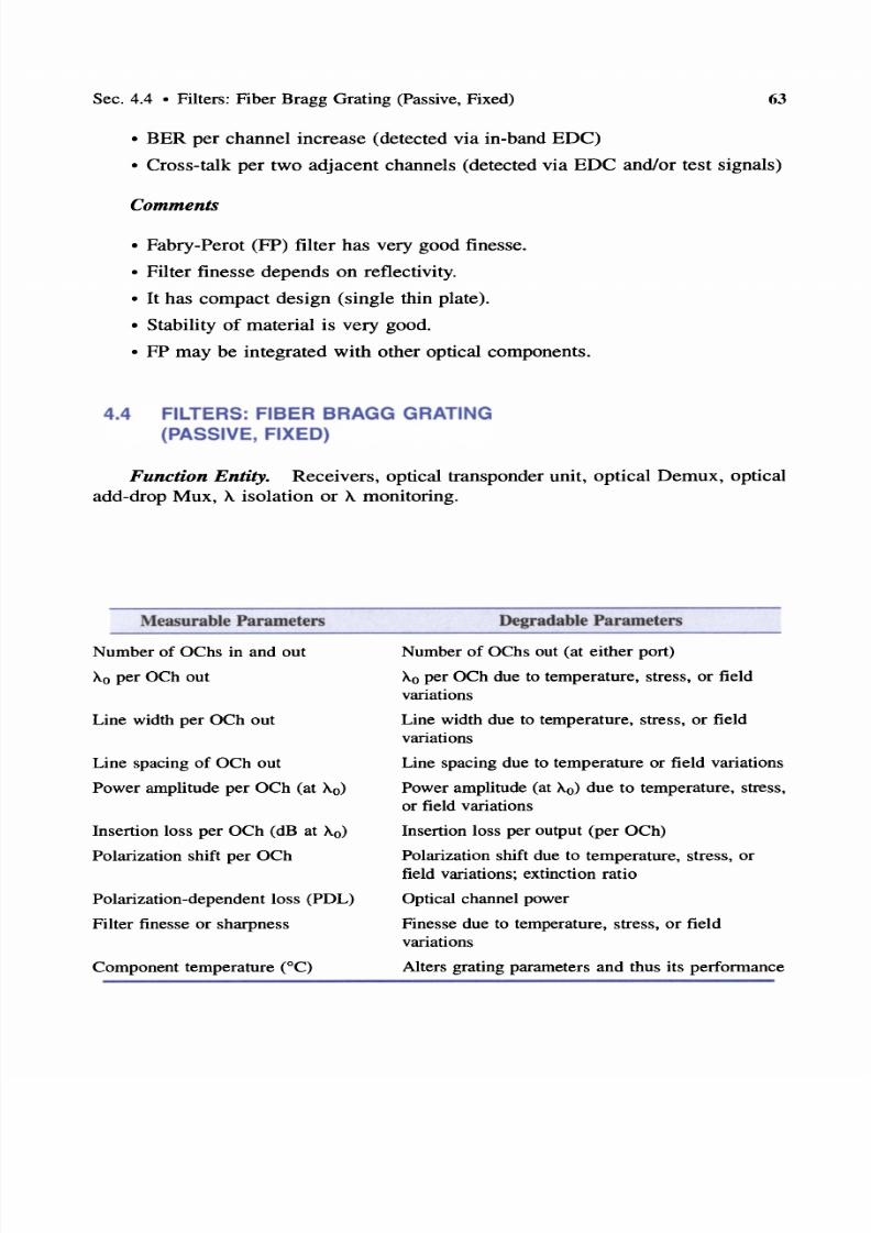
7/22/2019 Fault Detectability in DWDM - Toward Higher Signal Quality & System Reliability
http://slidepdf.com/reader/full/fault-detectability-in-dwdm-toward-higher-signal-quality-system-reliability 79/169
Sec. 4.4 • Filters: Fiber Bragg Grating (Passive, Fixed) 63
• BER per channel increase (detected via in-band EDC)
• Cross-talk per two adjacent channels (detected via EDC and/or test signals)
Comments
• Fabry-Perot (FP) filter has very good finesse.
• Filter finesse depends on reflectivity.
• It has compact design (single thin plate).
• Stability of material is very good.
• FP may be integrated with other optical components.
4.4 FILTERS: FIBER BRAGG GRATING
PASSIVE, FIXED
Function Entity. Receivers , optical transponder unit, optical Demux, optical
add-drop Mux, A isolation or Amonitoring.
Measurable Parameters
Number of OChs in and out
AO per OCh out
Line width per OCh out
Line spacing of OCh out
Power amplitude per OCh (at AO
Insertion loss per OCh (dB at AO
Polarization shift per OCh
Polarization-dependent loss (PDL)
Filter finesse or sharpness
Component temperature (0C)
Degradable Parameters
Number of Oehs out (at either port)
AO per OCh due to temperature, stress, or field
variations
Line width due to temperature, stress, or fieldvariations
Line spacing due to temperature or field variations
Power amplitude (at AO due to temperature, stress,
or field variations
Insertion loss per output (per OCh)
Polarization shift due to temperature, stress, or
field variations; extinction ratio
Optical channel power
Finesse due to temperature, stress, or field
variations
Alters grating parameters and thus its performance

7/22/2019 Fault Detectability in DWDM - Toward Higher Signal Quality & System Reliability
http://slidepdf.com/reader/full/fault-detectability-in-dwdm-toward-higher-signal-quality-system-reliability 80/169
64
Potential Faults
Chap. 4 • Faults Affecting the Optical DWDM Signal
Impact
Temperature, stress, or field variations
Fault Observability Symptoms)
Affect filter constants d,n)
and filter specs,AQ
per OCh, insertion loss per OCh, BER per OCh,
dispersion characteristics per OCh and extinction
ratio
• BER due to excessive spread of line width and/or optical power degradation
• Cross-talk due to excessive line-width spread
• Signal degradation at receiver BER (when optical power lowers)
• Signal loss (when optical power falls below receiver s quantum limit)
Fault Detectability from a System Viewpoint)
• AoiOCh shifts (detected via EDC and/or test signals)
• Optical power level of all channel drops (detected via EDC and/or test sig
nals)
• Optical power level of channels drops unevenly (some more than others due
to filter spectral response)
• BER per channel increases (detected via in-band EDC)
• Cross-talk per two adjacent channels (detect via EDC and/or test signals)
Comment
Fiber Bragg filters are compact.
Benefits
Connected in-line with the transmission fiber or other
component
Require fiber connector or fusion with fiber
May be integrated with other optical components
4.5 FILTERS: CHIRPED FBG (PASSIVE, FIXED
Function Entity. Receivers, optical transponder unit, optical Demux, disper
sion component, optical add-drop Mux, A isolation or Amonitoring.

7/22/2019 Fault Detectability in DWDM - Toward Higher Signal Quality & System Reliability
http://slidepdf.com/reader/full/fault-detectability-in-dwdm-toward-higher-signal-quality-system-reliability 81/169
Sec. 4.5 • Filter s: Chirped FBG (Passive, Fixed) 6S
Measurable Parameters Degradable Parameters
Number of OChs in and out
0 per OCh out
Line width per OCh out
Line spacing of OCh out
Power amplitude per OCh (at 0)
Insertion loss per OCh (dB at 0)
Polarization shift per OCh
Polarization-dependent loss (PDL)
Filter finesse or sharpness
Component temperature CC)
Potential FaultsTemperature, stress, or field variations
Number of OChs out (at either port)
0 per OCh due to temperature, stress, or field
variations
Line width due to temperature, stress, or field
variations
Line spacing due to temperature or field variations
Power amplitude (at 0) due to temperature, stress,
or field variations
Insertion loss per OCh out
Polarization shift due to temperature, stress, or field
variations; extinction ratio
Optical channel power
Finesse due to temperature, stress, or field variat ions
Alters grating parameters and thus its performance
ImpactVariations of filter constants d, n) affect filter
specifications
Affect Ao per OCh, insertion loss per OCh, BER
per OCh, and dispersion characteristics per OCh,
and extinction ratio
Fault Observability Symptoms)
• BER due to excessive spread of line width and/or optical power degradation
• Cross-talk due to excessive line-width spread
• Signal degradation at receiver BER (when optical power lowers)
• Signal loss (when optical power falls below receiver s quantum limit)
Fault Detectability from a System Viewpoint)
• X oI Ch shifts (detected via EDC and/or test signals)
• Optical power level of all channels drops (detected via EDC and/or test sig
nals)

7/22/2019 Fault Detectability in DWDM - Toward Higher Signal Quality & System Reliability
http://slidepdf.com/reader/full/fault-detectability-in-dwdm-toward-higher-signal-quality-system-reliability 82/169
66 Chap. 4 • Faults Affecting the Optical DWDM Signal
• Optical power level of channels drops unevenly (some more than others due
to filter spectral response)
• BER per channel increases (detected via in-band EDC)
• Cross-talk per two adjacent channels (detected via EDC and/or test signals)
Comment
Chirped Bragg filters are compact.
Benefits
May be integrated with other optical components
Filtered out OCh compensated for dispersion
Connected in-line with the transmission fiber orother component
Requires fiber connector or fusion with fiber
4.6 FILTERS: ACOUSTO-OPTIC TUNABLE Ti:LiNb0
Function Entity. Receivers, optical transponder unit, optical Demux, optical
add-drop Mux, Abroadcast, TE-TM converter, A isolation or monitoring.
Measurable Parameters
Tuning range
Wavelength resolutionInsertion loss
Filter bandwidth
Cross-talk
IF frequency shift
Component temperature
Polarization
Polarization-dependent loss (PDL)
Component temperature
Degradable Parameters
Range depends on filter (several nanometers or
urn
Wavelength resolution (on the order of 0.01 nm)Output power
Filter bandwidth
Signal-to-noise ratio SIN)
Wavelength stability
Filter characteristics
Polarization varies with temperature or voltage
variations; extinction ratio
PDL varies with frequency f) , temperature, or volt
age variations
Alters surface acoustic wave (SAW) filter parameters
and thus its performance

7/22/2019 Fault Detectability in DWDM - Toward Higher Signal Quality & System Reliability
http://slidepdf.com/reader/full/fault-detectability-in-dwdm-toward-higher-signal-quality-system-reliability 83/169
Sec. 4.6 • Filters : Acousto-Optic Tunable Ti:LiNb03
Potential Faults Impact
67
Misalignment of polarization state
Frequency shift due to Doppler effect
RF shift
RF power change (mW)
Temperature increase
*Not applicable in all implementations.
Fault Observability Symptoms)
Polarization mismatch that result s in coupling
loss
Wavelength registration mismatch*
Alters Bragg constant and filter tuning
Alters polarization state
Alters active area characteristics, passband,
polarization, Aregistration, and access time
• BER increase due to A misregistration
• BER increase due to OCh power decrease affected by RF power variations
• BER increase and OCh power level decrease due to change in polarization
state*
• Temperature changes alter all filter characteristics and specifications (BER,
cross-talk, SIN)
• Increased insertion loss increases BER
• Increased cross-talk decreases SIN
• SIN decrease, BER increase, and cross-talk increase due to slow tunability
Fault Detectability from a System Viewpoint)
• Increased IL (detected via EDC and/or test signals)
• Decreased SIN (detected via EDC and/or test signals)
• AoiOCh shifts due to component parametric changes of RF changes (detected
via EDC and/or test signals)
• Output power level drop (detected via EDC and/or test signals)
• Increased BER (detected via in-band EDC)
• Increased cross-talk per two adjacent channels (detected via EDC and/or test
signals)
*Not applicable in all implementations (two stage).

7/22/2019 Fault Detectability in DWDM - Toward Higher Signal Quality & System Reliability
http://slidepdf.com/reader/full/fault-detectability-in-dwdm-toward-higher-signal-quality-system-reliability 84/169
68
Comments
Solid-state construction
Broad tuning range
Narrow filter bandwidth, < 1 nm
Fast tunability, - 10 I ts
Acceptable insertion loss, < 5 dB
4.7 SOA: InGaAsP
Chap. 4 • Faults Affecting the Optical DWDM Signal
Benefits
Low cross-talk, < - 20 dB
One to many wavelength selection
Possible wavelength broadcast
Easy wavelength registration and stabilization
Function Entity. Optical amplifier, postamplifier (after optical transmitter),
preamplifier (before optical receiver), amplification within compound component
(e.g., Mux/Demux, OADM) .
Measurable Parameters*
Injection current
Input power range
Output power range
Noise figure (ASE)
Center frequency (at output)
Gain per OCh (at output)
Polarization
Component temperature
Degradable Parameters
Applied voltage (pump)
Output power
SIN
Center frequency ; line width
Gain per OCh
Extinction ratio
Alters SOA parameters and thus its and output power
*See ITU-T Recommendation G.662 for amplifier classifications and device characteristics.
Potential Faults
Injection current change
Coupling inefficiency
Temperature increase
Impact
Gain degradation, cross-talk, increased noise , possible loss of
signal (LOS)
Loss of gain, increased BER, possible LOS
Gain, output power, line width, polarization, cross-talk, noise;
temperature shifts and degrades power level

7/22/2019 Fault Detectability in DWDM - Toward Higher Signal Quality & System Reliability
http://slidepdf.com/reader/full/fault-detectability-in-dwdm-toward-higher-signal-quality-system-reliability 85/169
Sec. 4.7 • SOA: InGaAsP
Fault Observability Symptoms)
69
• Signal degradation at receiver; increased BER; cross-talk due to gain degradation/lost
• Signal degradation at receiver; decreased SIN due to gain degradation/lost
• Signal degradation at receiver; due to polarization effects
Fault Detectability from a System Viewpoint)
• Decreased SIN ratio (detected via EDC)
• Increased BER (detected via in-band EDC)
• Loss of signal (detected via power loss detector)
• X O shifts due to component parametric changes (detected via EDC and/or test
signals)
• Output power level drops (detected via EDC and/or test signals)
• Increased cross -talk (detected via EDC and/or test signals)
Comments
They are compact.
SOAs are polarization dependent.
They may be used as A converters.
They may be used as modulator/amplifiers.
They have an output saturation power in
the range of 5-10 dBm.
They have high noise figure and high
cross-talk level due to nonlinearities.
Benefits
They operate in the regions of 0.8, 1.3, and1.5 J.Lm and have high gain factor -20 dB).
They are integrable into arrays and with
other components .
They may require polarization-maintaining
fiber or circular polarizers.
In certain applications they eliminate the
need for amplification .
They can be tunable and have large
bandwidth.
They require good coupling with fiber ruse
antireflecting (AR) coating].

7/22/2019 Fault Detectability in DWDM - Toward Higher Signal Quality & System Reliability
http://slidepdf.com/reader/full/fault-detectability-in-dwdm-toward-higher-signal-quality-system-reliability 86/169
70 Chap. 4 • Faults Affecting the Optical DWDM Signal
4.8 OFA: FACTORS AFFECTING INTEGRITY AND
QUALITY OF SIGNAL
Optical fiber amplifiers are fibers heavily doped with a rare-earth element [erbium
(EDFA), praseodimium (PDFA), thulium and fluoride (ThDFA), and a mix of erbium
and titanium fiber amplifiers]. They operate on principles underlined by nonlinear
phenomena, ion excitation, and stimulated emission of light. Ions are excited by one
(or two) high-power laser(s) and the pump, and they are stimulated by the passing
photons of a weak signal, thus adding photons to the signal and amplifying it; the
pumps(s) emit light at different wavelengths. However, excited OFAs may emit spon
taneously light, known as amplifier spontaneous emission (ASE), that adds to the
noise of the signal (and thus decreases the SIN ratio). In this case, rejection optical
filters and isolators must be used to remove the wavelength of the pump(s).
In the following, we examine the factors that affect nonlinearities and polar
ization properties related to the transmission characteristics of OFAs (see ITU-T
Recommendation G.663) and controlling mechanisms. We also examine the single
and double-pump OFAs (EDFA and PDFA). No discrimination among pre-, post-,
or line-amplifiers is made here.
Optical Nonlinearities
• Stimulated Raman scattering SRS): OChs (at -1 W) may behave as a pump
for longer wavelengths or ASE degrading SIN ratio of other OChs. Not a
well-known controlling mechanism.
• Stimulated Brillouin scattering SBS): Threshold <5-10mW (external mode),
<20-30 mW (direct mode). Controlled by lowering signal intensity or make
source line width wider than Brillouin bandwidth (BW).
• Four-wave mixing FWM): Created sidebands may deplete OCh signal power.
Controlled by channel spacing selection (wide or uneven selection).
• Modulation instability MI): May reduce SIN due to created sidebands (and
thus decrease optical power level).
• Self-phase modulation SPM): Optical intensity changes change phase of sig
nal; this broadens the signal spectrum (pulse width). Operating in the anom
alous dispersion region, chromatic dispersion and SPM compensate eachother. This may result in spontaneous formation of solitons.
• Cross-phase modulation XPM): Interacting adjacent OChs induce phase
changes and thus pulse broadening. Controlled by selecting convenient chan
nel spacing.

7/22/2019 Fault Detectability in DWDM - Toward Higher Signal Quality & System Reliability
http://slidepdf.com/reader/full/fault-detectability-in-dwdm-toward-higher-signal-quality-system-reliability 87/169
Sec. 4.9 • OFA: Single Pump
Polarization Properties
71
• Polarization mode dispersion PMD): It changes randomly the polarizationstate of a pulse, causing pulse broadening. Controlled by polarization scram
blers, polarization controllers, or fiber selection.
• Polarization-dependent loss PDL): Due to dichroism of optical components.
It affects SIN and Q-value at the receiver. It may be controlled with polar
ization modulation techniques .
• Polarization hole burning PHB) : The selective depopulation of excited
states due to anisotropic saturation by a polarized saturating signal in EDFA
causes noise buildup. Controlled with depolarized signals or polarizationscramblers.
Other
• Dispersion properties: OFAs exhibit all fiber properties, including dispersion.
• Noise accumulation: ASE noise is amplified by subsequent OFAs and thus is
cumulative; it may exceed signal level SIN> 1) or surpass the 0/1 discrim
ination ability of the receiver.
• Temperature variations: Some temperature-sensitive components may require
component temperature stabilization (e.g., lasers, receivers) to maintain operation
within the specified parameters. Some othersmay operate withina range of tem
perature (e.g., 0-70°C) and only environmental conditioning may be required.
4.9 OFA: SINGLE PUMP
Function Entity. Optical in-line amplifier.
Measurable Parameters
Pump wavelength
Pump power
Spectral width (at output)
Gain
Gain differential across range
SIN
Temperature
Degradable Parameters
Pump wavelength may drift
Pump power level
Spectral width
Gain per OCh
Optical power per wavelength not flat
ASE adds to noise floor
Alters fiber parameters and thus its gain and flatness
response as well as pump efficiency and thus OFA gain
and flatness response

7/22/2019 Fault Detectability in DWDM - Toward Higher Signal Quality & System Reliability
http://slidepdf.com/reader/full/fault-detectability-in-dwdm-toward-higher-signal-quality-system-reliability 88/169
72
Potential Faults
Pump wavelength drift
Pump inoperable
Pump power decreases
Pump power increases
Gain of OChs degrades
Gain of certain OCh degrades
more than othersCoupler malfunctioning
ASE
Nonlinearities on certain
Temperature increase
Chap. 4 • Faults Affecting the Optical DWDM Signal
Impact
Gain decrease of certain xs, possible LOS of certainOChs
Loss of gain, increased BER, possible LOS of all OChs
Gain decrease, increased BER, possible LOS of certain
OChs
Nonlinear effects, increased BER and cross-talk
Possible increased BER and LOS of OChs
Possible increased BER and LOS of degraded OChs
Loss of gain, increased BER, possible LOS of all OChs
increased
Increased SIN ratio, increased BER
Increased BER and cross-talk
Degrades coupler, isolator, and fiber parameters
Fault Observability Symptoms)
• Signal degradation at receiver: increased cross-talk due to pump power degra
dation/lost and decreased SIN ratios due to increased ASE
• Signal loss due to gain lost and uncompensated power loss
Fault Detectability from a System Viewpoint)
• Pump power loss (detected by pump-monitoring device, or via EDC of all
OChs, LOS)
• Pump saturates OFA [detected by excessive BER, loss of (eye) signal but no
loss of optical power]
• Increased BER (detected via EDC, some or all OChs)
• Loss of signal (typically of all OChs)

7/22/2019 Fault Detectability in DWDM - Toward Higher Signal Quality & System Reliability
http://slidepdf.com/reader/full/fault-detectability-in-dwdm-toward-higher-signal-quality-system-reliability 89/169
Sec. 4.10 • OFA: Double Pump
Comments
OFAs have good gain factor.
Gain control is required.
Attenuation control is required to
not optically stress the fiber.
Fault localization strategy is
needed.
OFAs with Pr and Er-Ti are more
difficult to manufacture than
EDFA.
4.10 OFA: DOUBLE PUMP
73
Benefits
EDFA performs best in the C-band (1528-1561 nm).
Erbium-titanium EDFAs perform best in the C- and
L-bands (1561-1620 nm).
PDFA performs best in the 135Q-1528-nm range.
Thulium-doped fluoride fiber amplifier performs
best in the range about 1470 nm.
Optical equilizer at the receiver may be required .
OChs may suffer degradation due to FWM.
Cross-phase modulation (XPM) and SRS may berequired.
Channel equalization may be required.
Function Entity. In-line direct optical amplification (replaces regenerators),
postamplifiers, preamplifiers.
Measurable Parameters
Per-pump wavelength
Per-pump power
Spectral width (at output)
Gain
Gain differential over spectral range
SIN
Temperature
Degradable Parameters
Wavelength of each pump may drift
Power of each pump; pump power differential
Spectral width
Gain per OCh
Optical power per wavelength not flat
ASE adds to noise floor
Alters fiber parameters and thus its gain and flat
ness response as well as pump efficiency and thus
OFA gain and flatness response

7/22/2019 Fault Detectability in DWDM - Toward Higher Signal Quality & System Reliability
http://slidepdf.com/reader/full/fault-detectability-in-dwdm-toward-higher-signal-quality-system-reliability 90/169
74
Potential Faults
Pump wavelength drift
Pump inoperable
Pump power decreases
Pump power increases
Gain of OChs degrades
Gain of certain OChs
degrades more than othersCoupler malfunctioning
Increased ASE
Nonlinearities on certain AS
Temperature increase
Chap. 4 • Faults Affecting the Optical DWDM Signal
Impact
Gain degradation of certain AS, possible LOS of certainOChs
Loss of gain, increased BER, possible LOS of all OChs
Gain degradation, increased BER, possible LOS of certain
OChs
Strong nonlinear effects, increased BER and cross-talk
Possible increased BER and LOS of OChs
Possible increased BER and
LOS of degraded OChsLoss of gain, increased BER, possible LOS of all OChs
Increased SIN ratio, increased BER
Increased BER and cross-talk
Degrades coupler, isolator and fiber parameters, degrades
pump
Fault Observability Symptoms)
• Signal degradation at receiver; increased crosstalk due to pump power degra
dation/lost• Signal degradation at receiver; decreased SIN due to increased ASE
• Signal loss due to gain lost and uncompensated power loss
Fault Detectability from a System Viewpoint)
• Pump power loss (detected by pump-monitoring device, or via EDC of all
OChs, LOS); pump saturates OFA [detected by excessive BER, loss of sig
nal (eye) but not loss of optical power]
• Increased BER [detected via EDC, some or all OChs)]
• Loss of signal (mostly for all OChs)
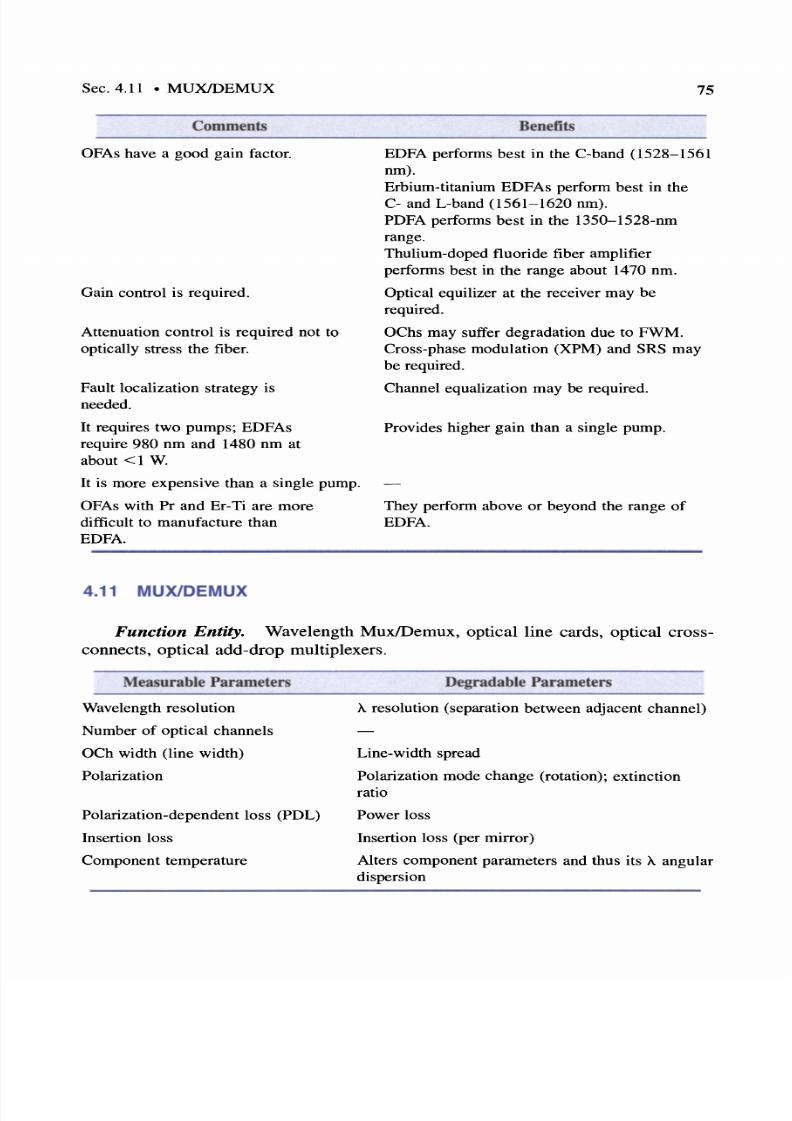
7/22/2019 Fault Detectability in DWDM - Toward Higher Signal Quality & System Reliability
http://slidepdf.com/reader/full/fault-detectability-in-dwdm-toward-higher-signal-quality-system-reliability 91/169
Sec. 4.11 • MUXlDEMUX
Comments
OFAs have a good gain factor.
Gain control is required.
Attenuation control is required not to
optically stress the fiber.
Fault localization strategy is
needed.
It requires two pumps ; EDFAs
require 980 nm and 1480 nm at
about < I W.
It is more expensive than a single pump.OFAs with Pr and Er-Ti are more
difficult to manufacture than
EDFA.
4.11 MUXlDEMUX
75
Benefits
EDFA performs best in the C-band (1528-1561
nm).
Erbium-titanium EDFAs perform best in the
C- and L-band (1561-1620 nm).
PDFA performs best in the 135Q-1528-nm
range.
Thulium-doped fluoride fiber amplifier
performs best in the range about 1470 nm.
Optical equilizer at the receiver may be
required.
OChs may suffer degradation due to FWM.
Cross-phase modulation (XPM) and SRS may
be required.
Channel equalization may be required.
Provides higher gain than a single pump.
They perform above or beyond the range of
EDFA.
Function Entity. Wavelength MuxlDemux, optical line cards, optical cross
connects, optical add-drop multiplexers.
Measurable Parameters
Wavelength resolution
Number of optical channels
OCh width (line width)
Polarization
Polarization-dependent loss (PDL)
Insertion loss
Component temperature
Degradable Parameters
A resolution (separation between adjacent channel)
Line-width spread
Polarization mode change (rotation); extinction
ratio
Power loss
Insertion loss (per mirror)
Alters component parameters and thus its A angular
dispersion
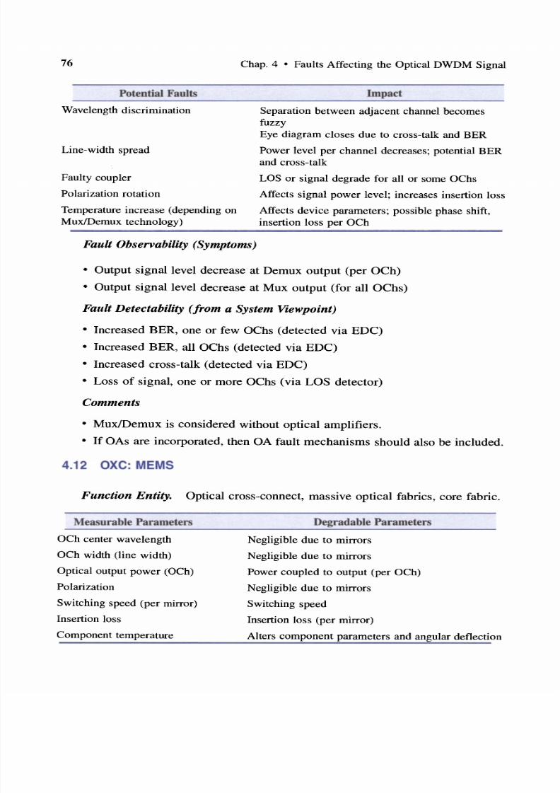
7/22/2019 Fault Detectability in DWDM - Toward Higher Signal Quality & System Reliability
http://slidepdf.com/reader/full/fault-detectability-in-dwdm-toward-higher-signal-quality-system-reliability 92/169
76
Potential Faults
Wavelength discrimination
Line-width spread
Faulty coupler
Polarization rotation
Temperature increase (depending on
MuxlDemux technology)
Chap. 4 • Faults Affecting the Optical DWDM Signal
Impact
Separation between adjacent channel becomesfuzzy
Eye diagram closes due to cross-talk and BER
Power level per channel decreases ; potential BER
and cross-talk
LOS or signal degrade for all or some OChs
Affects signal power level; increases insertion loss
Affects device parameters; possible phase shift,
insertion loss per OCh
Fault Observability Symptoms)
• Output signal level decrease at Demux output (per OCh)
• Output signal level decrease at Mux output (for all OChs)
Fault Detectability from a System Viewpoint)
• Increased BER, one or few OChs (detected via EDC)
• Increased BER, all OChs (detected via EDC)
• Increased cross-talk (detected via EDC)
• Loss of signal , one or more OChs (via LOS detector)
Comments
• Mux/Demux is considered without optical amplifiers.
• f OAs are incorporated, then OA fault mechanisms should also be included.
4.12 xe MEMS
Function Entity. Optical cross-connect, massive optical fabrics, core fabric.
Measurable Parameters
OCh center wavelength
OCh width (line width)
Optical output power aCh)
Polarization
Switching speed (per mirror)
Insertion loss
Component temperature
Degradable Parameters
Negligible due to mirrors
Negligible due to mirrors
Power coupled to output (per OCh)Negligible due to mirrors
Switching speed
Insertion loss (per mirror)
Alters component parameters and angular deflection

7/22/2019 Fault Detectability in DWDM - Toward Higher Signal Quality & System Reliability
http://slidepdf.com/reader/full/fault-detectability-in-dwdm-toward-higher-signal-quality-system-reliability 93/169
Sec. 4.12 • OXC: MEMS
Potential Faults
Faulty mirror (stuck at one
position)
Mirror does not rest at correct
position
Mirror oscillations (due to mirror
or electrical noise)
Temperature increase
77
Impact
Loss of OCh switching capability; possible BER and
cross-talk increase in other OChs
Degradation or possible loss of (OCh) power;
increased insertion loss; possible BER and cross-talk
increase in other OChs
Potential dispersion or jitter (due to Doppler?);
possible BER and cross-talk increase in other OChs
Affects all MEMS parameters; possible phase shift;
insertion loss per OCh; potential channel interference
Fault Observability Symptoms)
• OCh loss, one, few, or all
• OCh output power degradation, one, few, or all
• OCh switching capability loss, one, few, or all
• Mirror does not rest at correct position
Fault Detectability from a System Viewpoint)
• Loss of OCh output power (detected via LOS detector)
• Increased insertion loss, one, few, or all OChs*
• Increased BER and cross-talk,* one, few, or all
Comments
• Not easy to test each mirror in-system; needs testing strategy
• Not easy to fault-manage large N X N MEMS N = 1000?) on an OCh
basis
• Protection MEMS possible but requires splitters
*An all-optical detection scheme is preferred. Currently, it is detected by EDC, which requires op
tical-to-electrical (O-E) conversion.

7/22/2019 Fault Detectability in DWDM - Toward Higher Signal Quality & System Reliability
http://slidepdf.com/reader/full/fault-detectability-in-dwdm-toward-higher-signal-quality-system-reliability 94/169
78 Chap. 4 • Faults Affecting the Optical DWDM Signal
4.13 oxc. LiNb03
Function Entity. Optical cross-connect, small OXCs, medium-size fastswitching optical fabrics, wavelength distribution, small OADM.
Measurable Parameters
OCh center wavelength
OCh width (line width)
Optical output power
Polarization
Channel switching speed us)
Insertion loss (per OCh)
Component temperature
Potential Faults
Faulty coupler
Temperature increase
Degradable Parameters
Not applicable
Not applicable
Output power (per OCh)
PMD perOCh
Negligible change; determined by manufacturer over the
lifetime of component
Insertion loss (per OCh)
Alters component parameters and thus cross-connected
power and polarization state
Impact
Loss of switching capability for several OChs; possible BER
and cross-talk increase in other OCh
Affects device parameters; possible phase shift, insertion loss
per OCh
Fault Observability Symptoms)
• OCh loss (one or more)
• OCh output power degradation
• OCh switching capability loss
• Increased cross-talk
• Increased PMDIPDL
Fault Detectability from a System Viewpoint)
• Loss of OCh output power (detected via LOS)
• Increased insertion loss (detected via EDC)
• Increased BER and cross-talk (detected via EDC)

7/22/2019 Fault Detectability in DWDM - Toward Higher Signal Quality & System Reliability
http://slidepdf.com/reader/full/fault-detectability-in-dwdm-toward-higher-signal-quality-system-reliability 95/169
Sec. 4.14 • OXC Liquid Crystal
Comments
• Not easy to implement large N X N switches N = 64?)
• Needs testing st rategy
• Not easy to fault-manage large N X N switchers on an OCh basis
• Protection switch possible but requires splitters
• Requires cross-talk control
• Requires PMD/PDL control
• Requires equalization
4.14 OXC LIQUID CRYSTAL
79
Function Entity. Optical cross-connect, small OXC s, small optical fabrics,
wavelength distribution, small OADM, CWDM metro/access.
Measurable Parameters
OCh center wavelength
OCh width (line width)
Number of cross-connects N X N)
Optical output power (OCh)
Polarization
Switching speed (ms)
Insertion loss (per OCh)
Uniformity of in-out delay
Component (LC matrix)
temperature and pressure
Degradable Parameters
Not applicable
Not applicable
Cross-connecting pixel
Output power (per OCh)
PMD perOCh
Switching speed; determined by manufacturer over
lifetime of component
Insertion loss (per OCh)
Alters all component parameters

7/22/2019 Fault Detectability in DWDM - Toward Higher Signal Quality & System Reliability
http://slidepdf.com/reader/full/fault-detectability-in-dwdm-toward-higher-signal-quality-system-reliability 96/169
80
Potential Faults
Faulty coupler
Chap. 4 • Faults Affecting the Optical DWDM Signal
Impact
Loss of switching capability for several OChs;possible BER and cross-talk increase in other
OChs
Cross-connect failure
Temperature deviation from Toperational
Pressure deviation from Poperational
Fault Observability Symptoms)
• OCh power loss (one or more)
• OCh output power degradation
• OCh switching capability loss
• Increased cross-talk
• Increased PMD/PDL
Loose channel connectivity; blocking
Affects all device parameters (reflectivity, IL,
polarization, switching speed)
Affects all device parameters (reflectivity, IL,
polarization, switching speed)
Fault Detectability from a System Viewpoint)
• Loss of OCh output power (detected via LOS)
• Increased insertion loss (detected via EDC)
• Increased BER and cross-talk (?) (detected via EDC)
Comments
• In-out delay not uniform (varies per in-out connectivity)
• Currently, only small N X N switches N = 4, N = 32) possible
• Insertion loss -4 dB) per channel higher than other technologies
• Slow matrix switching speeds (several ms) lead to slow reconfiguration but
few channels
• Requires beam polarization control (depending on LC technology)
• Requires operation conditions (temperature pressure?) control
• Small, compact, and inexpensive
• Device reliability must be understood

7/22/2019 Fault Detectability in DWDM - Toward Higher Signal Quality & System Reliability
http://slidepdf.com/reader/full/fault-detectability-in-dwdm-toward-higher-signal-quality-system-reliability 97/169
Sec. 4.15 • OADM: LiNb03 Based
4.15 OADM: LiNb03 BASED
81
Function Entity. Wavelength distribution; OADM unit.This component, at minimum, consists of a passive multiplexer, a demulti
plexer, and LiNb03 switches. It can be integrated on one substrate or be assembled
with individual parts. The components that are used in an OADM determine the pa
rameters that could fail/degrade.
More complex OADMs may include MEMS array/matrix, filters, tunable array
waveguide gratings, or other technologies not included in this phase.
Measurable Parameters
OCh center wavelength
OCh width (line width)
Channel switching speed
Output optical power
Polarization
Insertion loss per channel
Switching speed per channel
Component temperature
Potential Faults
Faulty coupler
Temperature increase
Degradable Parameters
Not applicable
Not applicable
Determined by manufacturer over the lifetime of
component
Output power (per OCh)
PMD per OCh (in picoseconds); polarization sensitivity
(in fraction of a decibel); extinction ratio
Insertion loss (per OCh)
Switching speed
Alters component parameters and thus cross-connected
power and polarization state
Impact
Loss of switching capability for several OChs ; possible BER
and cross-talk increase in other OChs
Affects device parameters; possible phase shift, insertion loss
per OCh
Fault Observability Symptoms)
• OCh loss (one or more)
• OCh output power degradation
• OCh switching capability loss
• Increased cross-talk
• Increased PMDIPDL

7/22/2019 Fault Detectability in DWDM - Toward Higher Signal Quality & System Reliability
http://slidepdf.com/reader/full/fault-detectability-in-dwdm-toward-higher-signal-quality-system-reliability 98/169
82 Chap. 4 • Faults Affecting the Optical DWDM Signal
Fault Detectability from a System Viewpoint)
• Loss of OCh dropped (detected via LOS)
• Increased IL of OCh dropped (detected via EDC)
• Increased BER and cross-talk of OCh dropped (detected via EDC)
• Verification of added OCh frequency and power
Comments
• Not easy to implement large N X N OADM N = 64?); needs testing
strategy
• Requires verification of added OCh
• Requires verification strategy if dynamic allocation of OChs is supported
• Not easy to fault-manage large N X N switches on an OCh basis
• Protection switch possible but requires splitters
• Requires cross-talk control
• Requires PMD/PDL control
• Requires equalization
• Mayor may not use amplifiers
4.16 OADM: MEMS WITH GRATING
Function Entity. Optical cross-connect, large compact optical fabrics, wave
length distribution (large OADM).
This component consists of a passive grating (for Mux and for Demux), passive op
tics (lens, 1/4-A. plate), circulators, and MEMS. Consequently, the parameters that
could alter performance of an OADM and cause faults are the same as the MEMS
and gratings. In addition, subcomponent alignment changes due to physical stresses
(temperature, pressure, vibrations) and aging may result in further degradation ofparameters.
Parameter degradation, fault mechanisms, and their impact on performance are
dominated by gratings and MEMS (see corresponding entries above) as well as
packaging.

7/22/2019 Fault Detectability in DWDM - Toward Higher Signal Quality & System Reliability
http://slidepdf.com/reader/full/fault-detectability-in-dwdm-toward-higher-signal-quality-system-reliability 99/169
Sec. 4.17 • Transmitter: Laser
4.17 TRANSMITTER: LASER
83
Function Entity. Optical signal source, optical line cards, optical transponderunit.
Measurable Parameters
Output power
Wavelength (nm)
Line width
Electrical-to-optical efficiency
Tunability (tunable sources)
Polarization of beam
Extinction ratio (dB)
Stability
Modulation depth (with integrated
modulator)
Modulation rate [with integrated
modulator (MHz, GHz)]
Component temperature
Potential Faults
Degradable Parameters
Output power level
Center wavelength
Line width
Efficiency degradation affects output power
Tunability speed; wavelength range
Polarization of channel
Output power level
Wavelength and output power
Modulation depth (due to modulator
degradation/fault)
Rate degradation; spectral noise due to modulator
electrical feedback
A-shift; decrease of output power
Impact
Output power loss
Wavelength drift
Line-width broadening
Modulation depth changes
Tunability (tunable sources)
Temperature increase
Loss of signal (at near end and far end); excessive ASE
noise at far-end receiver (if OFA)
Degradation or loss of far-end received signal; SIN ratio
decreases due to BER and/or cross-talk
Decreases optical power; increases BER and/or cross-talk
BER due to inefficient demodulation; receiver ability to
discriminate Os and Is
Potential packet loss; potential loss of signallOCh
Spectral output, laser parameters (power, Ao, line width,
etc.)
Fault Observability Symptoms)
• Loss of laser output power at the transmitting end
• Laser output degradation (wavelength drift) due to bias and/or temperature
variations

7/22/2019 Fault Detectability in DWDM - Toward Higher Signal Quality & System Reliability
http://slidepdf.com/reader/full/fault-detectability-in-dwdm-toward-higher-signal-quality-system-reliability 100/169
84 Chap. 4 • Faults Affecting the Optical DWDM Signal
Fault Detectability from a System Viewpoint)
• Loss of optical signal (detected via a mechanism at the laser)
• Output power degradation (detected via EDC)
• Wavelength shift (detected via EDC)
• Decreased SIN (detected via EDC)
Comments
• Lasers components (package) are complex modules that contain a large num
ber of subcomponents to control the optical signal wavelength, line width,power level, temperature, and modulation parameters.
• Failure or degradation of any hidden subcomponent contributes to the over
all laser component fault analysis.
4.18 RECEIVER: PIN DIODE
Function Entity.
der unit.
Measurable Parameters
Quantum efficiency
Gain
Output current
Response time
Operating speed
Component temperature
Potential Faults
Gain degradation
Speed degradation
Ceases to detect photons
Dispersed receiving signal
Temperature increase
Optical signal receiver, optical line cards, optical transpon-
Degradable Parameters
Degrades with aging; provided by manufacturer
Degrades with aging ; affected by other parameters (voltage,
current, temperature)
Related to quantum efficiency and gain
Related to time constant and quantum efficiency
Related to response time
Lowers quantum efficiency and gain ; shifts A-sensitivity
Impact
Signal integrity, increased BER
Increased BER
Loss of incoming electrical signal
Increased BER due to lower optical level of signal, crosstalk, jitter due to optical/electrical phase-locked loop (PLL),
and BER due to SIN ratio decrease; possible loss of pointer
(LOP) if power level below diode threshold
Increased BER due to quantum efficiency decrease

7/22/2019 Fault Detectability in DWDM - Toward Higher Signal Quality & System Reliability
http://slidepdf.com/reader/full/fault-detectability-in-dwdm-toward-higher-signal-quality-system-reliability 101/169
Sec. 4.19 • Fiber: Single Mode
Fault Observability Symptoms)
85
• Loss of optical power per OCh within N = 4?) periods at the receiving enddeclares loss of signal (LOS).
Fault Detectability from a System Viewpoint)
• Loss of received optical signal (by one or more but not all receivers) termi
nating wavelengths within the fiber is detected via LOS detectors.• If a LOP by all receivers is detected (and there is no electrical power loss at
the receiver), then most likely the fiber is cut.
Comments
• A multiwavelength system is considered here.• It may use an optical preamplification stage.
• PIN diode components (package) are complex modules that contain a large
number of subcomponents, including filters and optical or electrical PLLs, to
control the optical signal threshold, OCh wavelength, synchronization, tem
perature, and demodulation parameters.
• Failure or degradation of any hidden subcomponent contributes to the over
all receiver component fault analysis.
4.19 FIBER: SINGLE MODE
Function Entity. Optical signal transmission medium. It is viewed as a key
component in the optican network and in the system, as it affects the transmitter
and the receiver.Note: This section does not discriminate among various fiber types. It regards
the fiber as a critical component that impacts the optical signal at the source and at
the receiver as well as the performance of many optical components. The interac
tion of light with fiber becomes more pronounced in multiwavelength systems.

7/22/2019 Fault Detectability in DWDM - Toward Higher Signal Quality & System Reliability
http://slidepdf.com/reader/full/fault-detectability-in-dwdm-toward-higher-signal-quality-system-reliability 102/169
86
Measurable Parameters
Length L, km)
Attenuation [A A), dBlkm]
Material dispersion coefficient
[Dmat(A), ps/nm-km]
Chromatic dispersion coefficient
[Dchr(A), ps/nm-km]
Polarization mode (TE, TM)
Zero-dispersion wavelength 1..0 , nm)
Birefringence
Stress, bend, temperature
Potential Faults
Chap. 4 • Faults Affecting the Optical DWDM Signal
Degradable Parameters
Signal power loss
Loss provided by manufacturer; by measuring
power signal at input and at output
Pulse spreading
Pulse spreading
Pulse spreading
Pulse spreading compensation
Power level and pulse spreading
Propagation and dispersion parameters
Impact
Fiber break
Fiber stress
Fiber bend
Loss of optical signal of all AS
All propagation and dispersion characteristics; affects all or some OChs
more than othersAll propagation and dispersion parameters; affects all or some OChs
more than others
Fault Observability Symptoms)
• Received optical power decreased• Loss of received power
Detected Fault
Loss of all signals
Increased BER and cross-talk of some
OChs
Increased BER and cross-talk of allOChs
Fault Correlation (from a System Viewpoint)
Fiber break; bad preamplifier OFA; bad OFA
Stress on fiber; bad preamplifier OFA; bad
OFA
Stress on fiber; bad preamplifier OFA; badOFA
Comments. System and networks fault management is required.

7/22/2019 Fault Detectability in DWDM - Toward Higher Signal Quality & System Reliability
http://slidepdf.com/reader/full/fault-detectability-in-dwdm-toward-higher-signal-quality-system-reliability 103/169
References
R F R N S
87
[1] S. V. Kartalopoulos, Introduction to DWDM: Data in a Rainbow, IEEE Press, NewYork, 2000.
[2] S. V. Kartalopoulos, Understanding SONETISDH and ATM: Communications Net
works for the next Millennium, IEEE Press, New York, 1999.
[3] R. Ramaswami and K. N. Sivarajan, Optical Networks, Morgan Kaufmann, San Fran
cisco, CA, 1998.
[4] B. Mukherjee, Optical Communication Networks, McGraw-Hill, New York, 1997.
[5] I. P. Kaminow, Ed., and T. L. Koch, Ed., Optical Fiber Communications IlIA and Op
tical Fiber Communications IIIB, Academic, New York, 1997.
[6] J. C. Palais, Fiber Optic Communications, 3rd ed., Prentice-Hall, Englewood Cliffs,NJ, 1992.
[7] R. G. Hunsperger, Integrated Optics: Theory and Technology, Springer-Verlag, New
York, 1984.
[8] S. Sudo, Ed., Optical Fiber Amplifiers: Materials, Devices, and Applications, Artech
House, Boston, 1997.
[9] J. Hecht, The Laser Guidebook, 2nd ed., Tab Books, Blue Ridge Summit, PA, 1992.
[10] T. Wildi, Units and Conversion Charts, 2nd ed., IEEE Press, New York, 1995.
[11] N. K. Dutta, III-V Device Technologies for Lightwave Applications, AT T Tech. J.,
vol. 68, no. 1, 1989, pp. 5-18.[12] J. J. Refi, Optical Fibers for Optical Networking, Bell Labs ech J., vol. 4, no. 1,
1999, pp. 246-261.
[13] R. J. Mears, L. Reekie, I. M. Jauncey, and D. N. Payne, Low-Noise Erbium-Doped
Fiber Amplifier Operating at 1.54 urn, Electron. Lett., vol. 23, no. 19, 1987, pp.
1026-1028.
[14] E. Desurvire, J. R. Simpson, and P. C. Becker, High-Gain Erbium-Doped Traveling
Wave Fiber Amplifiers, Opt. Lett., vol. 12, no. 11, 1987, pp. 888-890.
[15] K-W. Cheung, Acoustooptic Tunable Filters in Narrowband WDM Networks: System
Issues and Network Applications, IEEE JSAC, vol. 8, no. 6, 1990, pp. 1015-1025.
[16] D. A. Smith, J. E. Baran, J. J. Johnson, and K-W. Cheung, Integrated-Optic Acousti
cally-Tunable Filters for WDM Networks, IEEE JSAC, vol. 8, no. 6, 1990, pp.
1151-1159.
[17] S. R. Mallison, Wavelength-Selective Filters for Single-Mode Fiber WDM Systems
Using Fabry-Perot Interferometers, Appl. Opt., vol 26, 1987, pp. 430-436.
[18] N. Goto and Y. Miyazaki, Integrated Optical Multi-lDemultiplexer Using Acous
tooptic Effect for Multiwavelength Optical Communications, IEEE JSAC, vol. 8, no.
6, 1990, pp. 1160-1168.
[19] N. Takato et al., Silica-Based Integrated Optic Mach-Zehnder MultilDemultiplexerFamily with Channel Spacing of 0.01-250 nm, IEEE JSAC, vol. 8, no. 6, 1990, pp.
1120-1127.
[20] R. C. Alfemess, Waveguide Electro-Optic Modulators, IEEE Trans. Microwave The
ory Techn., vol. MTT-30, 1982, pp. 1121-1137.

7/22/2019 Fault Detectability in DWDM - Toward Higher Signal Quality & System Reliability
http://slidepdf.com/reader/full/fault-detectability-in-dwdm-toward-higher-signal-quality-system-reliability 104/169
88 Chap. 4 • Faults Affecting the Optical DWDM Signal
[21] R. C. Alferness, Guided-Wave Devices for Optical Communication, IEEE J. Quant.
Electron., vol. QE-17, 1981, pp. 946-949.
[22] R. C. Alferness and L. L. Buhl, Low-Cross-Talk Waveguide Polarization Multiplexer/Demultiplexer for X = 1.32 J,Lm, Opt. Lett., vol. 10, 1984, pp. 140-142.
[23] T. K. Findakly, Glass Waveguides by Ion Exchange: A Review, Opt. Eng., vol. 24,
1985, pp. 244-255.
[24] W.Warzanskyj, F. Heismann, and R. C. Alferness, Polarization-Independent Electro
Acoustically Tunable Narrow-Band Wavelength Filter, Appl. Phys. Lett., vol. 56,
1990, pp. 2009-2011.
[25] J. Frangen et aI., Integrated Optical, Acoustically-Tunable Wavelength Filter, Proc.
6th European Conf. Integrated Opt., Paris, SPIE, 1989, post-deadline paper.
[26] F. Heismann, L. Buhl, and R. C. Alferness, Electrooptically Tunable NarrowbandTi:LiNb03 Wavelength Filter, Electron. Lett., vol. 23, 1987, pp. 572-573.
[27] F. Ouellette, All-Fiber for Efficient Dispersion Compensation, Opt. Lett., vol. 16, no.
5, 1991, pp. 303-304.
[28] R. M. Measures, A. T. Alavie, M. LeBlanc, S. Huang, M. Ohn, R. Masskant, and
D. Graham, Controlled Grating Chirp for Variable Optical Dispersion Compensa
tion, Proceedings, 13th Annual Conference on European Fiber Optic Communica
tions and Networks, Brighton, England, 1995, pp. 38-41.
[29] G. D. Boyd and F. Heismann, Tunable Acoustooptic Reflection Filters in LiNb03
without a Doppler Shift, J. Lightwave Technol., vol. 7, 1989, pp. 625-631.[30] L. G. Kazovsky, Optical Signal Processing for Lightwave Communications Net
works, IEEE JSAC, vol. 8, no. 6, 1990, pp. 973-982.
[31] S. E. Miller, Coupled-Wave Theory and Waveguide Applications, Bell Syst. Tech. J.,
vol. 33, 1954, pp. 661-719.
[32] A. Yariv, Coupled Mode Theory for Guided Wave Optics, IEEE J. Quant. Electron.,
vol. QE-9, 1973, pp. 919-933.
[33] D. Sadot and E. Boimovich, Tunable Optical Filters for Dense WDM Networks,
IEEE Commun. Mag., vol. 36, no. 12, 1998, pp. 50-55.
[34] M. Zirngibl, Multifrequency Lasers and Applications in WDM Networks, IEEECommun. Mag., vol. 36, no. 12, 1998, pp. 39-41.
[35] S. D. Personick, Receiver Design for Digital Fiber Optic Communication Systems,
I, Bell Syst. ech J., vol. 52, no. 6, 1973, pp. 843-874.
[36] S. D. Personick, Receiver Design for Digital Fiber Optic Communication Systems,
II, Bell Syst. ech J., vol. 52, no. 6, 1973, pp. 875-886.
[37] F. Tong, Multiwavelength Receivers for WDM Systems, IEEE Commun. Mag., vol.
36, no. 12, 1998,pp. 42-49.
[38] K. A. McGreer, Arrayed Waveguide Grating for Wavelength Routing, IEEE Com
mun. Mag., vol. 36, no. 12, 1998, pp. 62-68.
[39] A. Iocco, H. G. Limberger, and R. P. Salathe, Bragg Grating Fast Tunable Filter,
Electron. Lett., vol. 33, no. 25, 1997, pp. 2147-2148.
[40] M. K. Smit and C. van Dam, PHASAR-Based WDM-Devices: Principles, Design
and Application, IEEE J. Sel. Topics Quant. Electron., vol. 2, no. 2, 1996, pp.
236-250.

7/22/2019 Fault Detectability in DWDM - Toward Higher Signal Quality & System Reliability
http://slidepdf.com/reader/full/fault-detectability-in-dwdm-toward-higher-signal-quality-system-reliability 105/169
References 89
[41] H. Tanobe et al, Temperature Insensitive Arrayed Waveguide Gratings on InP Sub
strate, IEEE Photon Tech. Lett., vol. 10, no. 2, 1998, pp. 235-237.
[42] D. Nesset, T. Kelly, and D. Marcenac, All-Optical Wavelength Conversion UsingSOA Nonlinearities, IEEE Commun. Mag., vol. 36, no. 12, 1998, pp. 56-61.
[43] J. M. Senior and S. D. Cusworth, Devices for Wavelength Multiplexing and Demul
tiplexing, lEE Proc., vol. 136, no. 3, 1989, pp. 183-202.
[44] Y. K. Chen and C. C. Lee, Fiber Bragg Grating-Based Large Nonblocking Multiwave
length Cross-Connects, 1. Lightwave Techno ., vol. 16, no. 10, 1998, pp. 1746-1756.
[45] C. R. Doerr, Proposed WDM Cross Connect Using a Planar Arrangement ofWave
guide Grating Routers and Phase Shifters, IEEE Photon. Technol. Lett., vol. 10, 1998,
pp. 528-530.
[46] J. E. Ford, V. A. Aksyuk, D. J. Bishop, and J. A. Walker, Wavelength Add/DropSwitching Using Tilting Micromirrors, J. Lightwave Technol., vol. 17, no. 5, 1999,
pp. 904-911.
[47] J. R. Thompson and R. Roy, Multiple Four-Wave Mixing Process in an Optical
Fiber, Opt. Lett., vol. 16, no. 8, 1991, pp. 557-559.
[48] K. Inoue, Experimental Study on Channel Crosstalk Due to Fiber Four-Wave Mixing
around the Zero-Dispersion Wavelength, IEEE J. Lighwave Technol., vol. LT-12, no.
6, 1994,pp. 1023-1028.
[49] C. A. Brackett, Dense Wavelength Division Multiplexing Networks: Principles and
Applications, IEEE JSAC, vol. 8, no. 6, 1990, pp. 948-964.[50] C. R. Giles and M. Spector, The Wavelength Add/Drop Multiplexer for Lightwave
Communication Networks, Bell Labs Tech. J., vol. 4, no. 1, 1999, pp. 207-229.
[51] U. Koren et aI., Wavelength Division Multiplexing Light Sources with Integrated
Quantum Well Tunable Lasers and Optical Amplification, Appl. Phys. Lett., vol. 54,
1989,pp.2056-2058.
[52] G. Coquin, K. W. Cheung, and M. Choy, Single- and Multiple-Wavelength Operation
of Acousto-Optically Tuned Lasers at 1.3 Microns, Proc. 11th IEEE Int. Semicon
ductor Laser Conf., Boston, 1988, pp. 130-131.
[53] H. Kobrinski and K. W. Cheung, Wavelength-Tunable Optical Filters: Applicationsand Technologies, IEEE Commun. Mag., vol. 27, 1989, pp. 53-63.
[54] S. Suzuki et aI., A Photonic Wavelength-Division Switching System Using Tunable
Laser Diode Filters, ICC '89 Conference Records, Boston, 1989, paper 23.1.
[55] C. Dragone, Efficient N X N Star Couplers Using Fourier Optics, J. Lightwave Tech
nol., vol. 7, 1989, pp. 479-489.
[56] C. M. Ragdale, D. Reid, D. J. Robbins, and J. Buus, Narrowband Fiber Grating Fil
ters, IEEE JSAC, vol. 8, no. 6,1990, pp. 1146-1150.
[57] Y. Sun, A. K. Srivastava, J. Zhou, and J. W. Sulhoff, Optical Fiber Amplifiers for
WDM Optical Networks, Bell Labs Tech. J., vol. 4, no. 1, 1999, pp. 187-206.
[58] M. J. Adams, Theory of Twin-Guide Fabry-Perot Laser Amplifiers, lEE Proc., vol.
136, no. 5, 1989,pp. 287-292.
[59] G. J. Cannell , A. Robertson, and R. Worthington, Practical Realization of a High
Density Diode-Coupled Wavelength Demultiplexer, IEEE JSAC, vol. 8, no. 6, 1990,
pp. 1141-1145.
7/22/2019 Fault Detectability in DWDM - Toward Higher Signal Quality & System Reliability
http://slidepdf.com/reader/full/fault-detectability-in-dwdm-toward-higher-signal-quality-system-reliability 106/169
90 Chap. 4 • Faults Affecting the Optical DWDM Signal
[60] A. J. Lowery, Computer-Aided Photonics Design, IEEE Spectrum, vol. 34, no. 4,
1997, pp. 26--31.
[61] K. S. Giboney, L.A. Aronson, and B. E. Lemoff, The Ideal Light Source for Datanets,IEEE Spectrum, vol. 35, no. 2, 1998, pp. 43-53.
[62] M-C. Amann and W. Thulke, Continuously Tunable Laser Diodes: Longitudinal ver
sus Transverse Tuning Scheme, IEEE JSAC, vol. 8, no. 6,1990, pp. 1169-1177.
[63] K. Kobayashi and I. Mito, Single Frequency and Tunable Laser Diodes, J. Light
wave Technol., vol 6, 1988, pp. 1623-1633.
[64] L. A. Coldren and S. W. Corzine, Continuously Tunable Single Frequency Semicon
ductor Lasers, IEEE J. Quantum Electron., vol. QE-23, 1987, pp. 903-908.
[65] M. Okuda and K. Onaka, Tunability of Distributed Bragg Reflector Laser by Modu
lating Refractive Index in Corrugated Waveguide, Jpn. J. Appl. Phys., vol. 16, 1977,pp. 1501-1502.
[66] Y. Kotaki, M. Matsuda, H. Ishikawa, and H. Imai, Tunable DBR Laser with Wide
Tuning Range, Electron. Lett., vol. 24, 1988, pp. 503-505.
[67] H. A. Haus, Wavesand Fields in Optoelectronics, Prentice-Hall, Englewood Cliffs, NJ,
1984.
[68] S. Adachi, Refractive Indices of III-IV Compounds: Key Properties of InGaAsP Rel
evant to Device Design, J. Appl. Phys., vol. 53, 1982, pp. 5863-5869.
[69] J. Stone and D. Marcuse, Ultrahigh Finesse Fiber Fabry-Perot Interferometers,
J. Lightwave Technol., vol. LT-4, no. 4, 1986, pp. 382-385.[70] A. A. M. Saleh and J. Stone, Two-Stage Fabry-Perot Filters as Demultiplexers in Op
tical FDMA LAN s, J. Lightwave Technol., vol. LT-7, 1989, pp. 323-330.
[71] S. R. Mallinson, Wavelength Selective Filters for Single-Mode Fiber WDM Systems
Using Fabry-Perot Interferometers, Appl. Opt., vol. 26, 1987, pp. 430-436.
[72] A. M. Hill and D. B. Payne, Linear Crosstalk inWavelength Division Multiplexed Op
tical Fiber Transmission Systems, J. Lightwave Technol., vol. LT-3, 1985, pp. 643-651.
[73] G. Hernandez, Fabry-Perot Interferometers, Cambridge University Press, Cambridge,
1986.
[74] F. J. Leonberger, Applications of Guided-Wave Interferometers, Laser Focus, Mar.1982, pp. 125-129.
[75] H. Van de Stadt and J. M. Muller, Multimirror Fabry-Perot Interferometers, J. Opt.
Soc. Am. A, vol. 2, 1985, pp. 1363-1370.
[76] P.A. Humblet and W. M. Hamdy, Crosstalk Analysis and Filter Optimization of Sin
gle- and Double-Cavity Fabry-Perot Filters, IEEE JSAC, vol. 8, no. 6, 1990, pp.
1095-1107.
[77] K. Y. Eng, M. A. Santoro, T. L. Koch, J. Stone, and W. W. Snell, Star-Coupler-Based
Optical Cross-Connect Switch Experiments with Tunable Receivers, IEEE JSAC, vol.
8,no. 6, 1990,pp. 1026-1031.[78] H. Toba, K. Oda, K. Nosu, and N. Takato, Factors Affecting the Design of Optical
FDM Information Distribution Systems, IEEE JSAC, vol. 8, no. 6, 1990, pp. 965-972.
[79] H. Onaka, et al., 1.1 ThIs WDM Transmission Over a 150 KIn 1.3 Zero-Dispersion
Single-Mode Fiber, OFC 6, San Jose, CA, Feb. 1996, pp. PD19:1-5.

7/22/2019 Fault Detectability in DWDM - Toward Higher Signal Quality & System Reliability
http://slidepdf.com/reader/full/fault-detectability-in-dwdm-toward-higher-signal-quality-system-reliability 107/169
References 9
[80] A. R. Chraplyvy, Optical Power Limits in Multi-Channel Wavelength-Division-Mul
tiplexed System due to Stimulated Raman Scattering, Electron. Lett., vol. 20, no. 2,
1984, pp. 58-59.[81] K. Inoue, Four-Wave Mixing in an Optical Fiber in the Zero-Dispersion Wavelength
Region, IEEE J. Lightwave Technol., vol. LT-I0, no. 11, 1992, pp. 1553-1563.
[82] K. Inoue, Suppression of Fiber Four-WaveMixing in Multichannel Transmission Us
ing Birefringent Elements, IEICE Trans. Commun., vol. E76-B, no. 9, 1993, pp.
1219-1221.
[83] K. Nosu, Optical FDM Network Technologies, Artech House, Boston, 1997.
[84] M. Cvijetic, Coherent and Nonlinear Lightwave Communications, Artech House,
Boston, 1996.
[85] H. Toba and K. Nosu, Optical Frequency Division Multiplexing System-Review ofKey Technologies and Applications, IEICE Trans. Commun., vol. E75-B, no. 4, 1992,
pp. 243-255.
[86] D. Cotter, Stimulated Brillouin Scattering in Monomode Optical Fiber, J. Opt. Com
mun., vol. 4, 1983, pp. 10-16.
[87] P. S. Henry, Lightwave Primer, IEEE J. Quant. Electron., vol. QE-21, 1985, pp.
1862-1879.
[88] M. Kawasaki, Silica Waveguides on Silicon and Their Application to Integrated Op
tic Components, Opt. Quant. Electron., vol. 22, 1990, pp. 391-416.
[89] L. Kazovsky, S. Benedetto, and A. Willner, Optical Fiber Communication Systems,Artech House, Boston, 1996.
[90] N. A. Jackman, S. H. Patel, B. P. Mikkelsen, and S. K. Korotky, Optical Cross Con
nect for Optical Networking, Bell Labs Tech. J., vol. 4, no. 1, 1999, pp. 262-281.
[91] H. Takahashi et aI., Arrayed-Waveguide Grating for Wavelength Division Multiplex
ing/Demultiplexing with Nanometer Resolution, Electron. Lett., vol. 26,1990, pp. 87-88.
[92] 1. Minowa and Y. Fujii, Dielectric Multilayer Thin Film Filters for WDM Transmis
sion, IEEE J. Lightwave Technol., vol. 1, no. 1, 1983, pp. 116-121.
[93] W. K. Chen, Passive and Active Filters, Wiley, New York, 1986.
[94] R. Watanabe et aI., Optical MultilDemultiplexers for Single-Mode Fiber Transmission, IEEE J. Quant. Electron., vol. 17, no. 6,1981, pp. 947-951.
[95] Y. Hibino et aI., High Reliability Silica Based PLC lX8 Splitters on Si, Electron.
Lett., vol. 30, no. 8, 1994, pp. 640-641.
[96] K. Kato et aI., Packaging of Large-Scale Integrated Optic N X N Star Couplers,
IEEE Photon. Technol. Lett., vol. 4, no. 33, 1993, pp. 348-351.
[97] H. Rokugawa et aI., Wavelength Conversion Laser Diodes Application to Wave
length-Division Photonic Cross-Connect Node with Multistage Configuration, IEICE
Trans. Commun., vol. E-75-B, no. 4, 1992, pp. 267-273.
[98] o. Ishida and H. Toba, A 1.55-mm Lightwave Frequency Synthesizer, IEICE Trans.Commun., vol. E75-B, no. 4, 1992, pp. 275-280.
[99] K. Vilhelmsson, Simultaneous Forward and Backward Raman Scattering in Low
Attenuation Single-Mode Fibers, J. Lightwave Technol., vol. LT-4, no. 4, 1986, pp.
400-404.

7/22/2019 Fault Detectability in DWDM - Toward Higher Signal Quality & System Reliability
http://slidepdf.com/reader/full/fault-detectability-in-dwdm-toward-higher-signal-quality-system-reliability 108/169
92 Chap. 4 • Faults Affecting the Optical DWDM Signal
[100] H. Kobrinski and K-W. Cheung, Wavelength-Tunable Optical Filters: Applications
and Technologies, IEEE Commun. Mag., Oct. 1989, pp. 53-63.
[101] R. Tewari and K. Thyagarajan, Analysis of Tunable Single-Mode Fiber DirectionalCouplers Using Simple and Accurate Relations, J. Lightwave Technol., vol. LT-4, no.
4, 1986,pp. 386-399.
[102] N. Kashima, Passive Optical Components for Optical Fiber Transmission, Artech
House, Boston, 1995.
[103] S. Kawakami, Light Propagation along Periodic Metal-Dielectric Layers, Appl. Opt.,
vol. 22, 1983, p. 2426.
[104] K. Shiraishi, S. Sugayama, K. Baba, and S. Kawakami, Microisolator, Appl. Opt.,
vol. 25, 1986, p. 311.
[105] K. Shiraishi, S. Sugayama, and S. Kawakami, Fiber Faraday Rotator, Appl. Opt., vol.23, 1984, p. 1103.
[106] W. Eickhoff, In-Line Fiber-Optic Polarizer, Electron. Lett., vol. 6, 1980, p. 762.
[107] T. Hosaka, K. Okamoto, and J. Noda, Single-Mode Fiber Type Polarizer, IEEE J.
Quant. Electron., vol. QE-18, 1982, p. 1569.
[108] R. A. Bergh, H. C. Lefevre, and H. J. Shaw, Single-Mode Fiber-Optic Polarizer, Opt.
Lett., vol. 5, 1980, p. 479.
[109] J. C. Palais, Fiber Optic Communications, 3rd ed., Prentice-Hall, Englewood Cliffs,
NJ,1992.
[110] M. Francon, Optique: formation et traitment des images, Macon Cie, Paris, 1972.
[111] T. G. Robertazzi, Ed., Performance Evaluation ofHigh Speed Switching Fabrics and
Networks, IEEE Press, New York, 1993.
[112] Y. Pan, C. Qiao, and Y. Yang, Optical Multistage Interconnection Networks: New
Challenges and Approaches, IEEE Commun. Mag., vol. 37, no. 2, 1999, pp. 50-56.
[113] J. G. Eden, Photochemical Processing of Semiconductors: New Applications for Vis
ible and Ultraviolet Lasers, IEEE Circuits Devices Mag., vol. 2, no. 1, 1986, pp. 18-24.
[114] R. J. von Gutfeld, Laser-Enhanced Plating and Etching for Microelectronic Applica
tions, IEEE Circuits Devices Mag., vol. 2, no. 1, 1986, pp. 57-60.
[115] J. Bokor) A. R. Neureuther, and W. G. Oldham, Advanced Lithography for ULSI,IEEE Circuits Devices Mag., vol. 12, no. 1, 1996, pp. 11-15.
[116] A. Yariv, Quantum Well Semiconductor Lasers Are Taking Over, IEEE Circuits De
vices Mag., vol. 5, no. 6, 1989, pp. 25-28.
[117] J. LaCourse, Laser Primer for Fiber-Optics Users, IEEE Circuits Devices Mag., vol.
8,no.2, 1992,pp. 27-32.
[118] Z. V. Nesterova and I. V. Aleksaandrov, Optical-Fiber Sources of Coherent Light,
Sov. J. Opt. Technol., vol 54, no. 3, 1987, pp. 183-190.
[119] T. Komukai et aI., Upconversion Pumped Thulium-Doped Fluoride Fiber Amplifier
andLaser Operating at 1.47 J,Lm, IEEE Quant. Electron., vol. 31,1995, pp. 1880-1889.
[120] G. Eisenstein, Semiconductor Optical Amplifiers, IEEE Circuits Devices Mag., vol.
5,no. 4, 1989,pp. 25-30.
[121] C. F. Buhrer, Four Waveplate Dual Tuner for Birefringent Filters and Multiplexers,
Appl. Opt., vol. 26, no. 17, 1987, pp. 3628-3632.
7/22/2019 Fault Detectability in DWDM - Toward Higher Signal Quality & System Reliability
http://slidepdf.com/reader/full/fault-detectability-in-dwdm-toward-higher-signal-quality-system-reliability 109/169
References 93
[122] J. W. Evans, The Birefringent Filter, J. Opt. Soc. Am., vol. 39, 1949, p. 229.
[123] H. Hinton, An Introduction to Photonic Switching Fabrics, Plenum, New York, 1993.
[124] C. Tocci and H. J. Caufield, Optical Interconnection-Foundations and Applications,Artech House, Boston, 1994.
[125] A. Budman et aI., Multi-Gigabit Optical Packet Switch for Self-Routing Networks
with Subcarrier Addressing, Proc. OFC 2, San Jose, CA, Feb. 1992, paper Tu04.
[126] C-K. Chan, L-K. Chen, and K-W. Cheung, A Fast Channel-Tunable Optical Trans
mitter for Ultrahigh-Speed All-Optical Time-Division Multi-Access Network, IEEE
JSAC, vol. 14, no. 5, 1996, pp. 1052-1056.
[127] K. Padmanabhan and A. N. Netravali, Dilated Networks for Photonic Switching,
IEEE Trans. Commun., vol. 35, no. 12, 1987, pp. 1357-1365.
[128] C. Qiao et aI., A Time Domain Approach for Avoiding Crosstalk in Optical BlockingMultistage Interconnection Networks, J. Lightwave Technol., vol. 12, no. 10, 1994,
pp. 1854-1862.
[129] R. A. Thompson, The Dilated Slipped Banyan Switching Network Architecture for
Use in an All-Optical Local-Area Network, J. Lightwave Technol., vol. 9, no. 12,
1991, pp. 1780-1787.
[130] D. Hunter and D. Smith, New Architecture for Optical TDM Switching, J. Light
wave Technol., vol. 11, no. 3, 1993, pp. 495-511.
[131] E. Nussbaum, Communication Network Needs and Technologies-A Place for Pho
tonic Switching, IEEE JSAC, vol. 6, no. 7, 1988, pp. 1036-1043.[132] S. A. Cassidy and P. Yennadhiou, Optimum Switching Architectures Using D-Fiber
Optical Space Switches, IEEE JSAC, vol. 6, no. 7, 1988, pp. 1044-1051.
[133] C. J. Smith, Nonblocking Photonic Switch Networks, IEEE JSAC, vol. 6, no. 7,
1988,pp.1052-1062.
[134] J. D. Evankow, Jr. and R. A. Thompson, Photonic Switching Modules Designed with
Laser Diode Amplifiers, IEEE JSAC, vol. 6, no. 7, 1988, pp. 1087-1095.
[135] W. D. Johnston, Jr., M. A. DiGiuseppe, and D. P. Wilt, Liquid and Vapor Phase
Growth of III-V Materials for Photonic Devices, AT T Tech. J., vol. 68, no. 1, 1989,
pp.53-63.
[136] W. G. Dautremont-Smith, R. J. McCoy, and R. H. Burton, Fabrication Technologies
for III-V Compound Semiconductor Photonic and Electronic Devices, AT T Tech.
J., vol. 68, no. 1, 1989, pp. 64-82.
[137] N. K. Dutta, III-V Device Technologies for Lightwave Applications, AT T Tech. J.,
vol. 68, no. 1, 1989, pp. 5-18.
[138] K. Y. Eng, A Photonic Knockout Switch for High-Speed Packet Networks, IEEE
JSAC, vol. 6, no. 7, 1988, pp. 1107-1116.
[139] R. C. Alfemess, Waveguide Electrooptic Switch Arrays, IEEE JSAC, vol. 6, no. 7,
1988, pp. 1117-1130.[140] T. Ikegami and H. Kawaguchi, Semiconductor Devices in Photonic Switching, IEEE
JSAC, vol. 6, no. 7, 1988, pp. 1131-1140.
[141] R. I. Macdonald, Terminology for Photonic Matrix Switches, IEEE JSAC, vol. 6, no.
7,1988, pp. 1141-1151.

7/22/2019 Fault Detectability in DWDM - Toward Higher Signal Quality & System Reliability
http://slidepdf.com/reader/full/fault-detectability-in-dwdm-toward-higher-signal-quality-system-reliability 110/169
94 Chap. 4 • Faults Affecting the Optical DWDM Signal
[142] J. V.Wright, S. R. Mallinson, and C. A. Millar, A Fiber-Based Crosspoint Switch Using
High-Refractive Index InterlayMaterials, IEEE JSAC, vol. 6, no. 7, 1988, pp. 1160-1168.
[143] J. Skinner and C. H. R. Lane, A Low-Crosstalk Microoptic Liquid Crystal Switch,IEEE JSAC, vol. 6, no. 7,1988, pp. 1178-1185.
[144] T. Morioka and M. Saruwatari, Ultrafast All-Optical Switching Utilizing the Optical
Kerr Effect in Polarization-Maintaining Single-Mode Fibers, IEEE JSAC, vol. 6, no.
7, 1988, pp. 1186-1198.
[145] H. S. Hinton, Architectural Considerations for Photonic Switching Networks, IEEE
JSAC, vol. 6, no. 7, 1988, pp. 1209-1226.
[146] H. Inoue, H. Nakamura, K. Morosawa, Y. Sasaki, T. Katsuyama, and N. Chinone, An
8 mm Length Nonblocking 4 X 4 Optical Switch Array, IEEE JSAC, vol. 6, no. 7,
1988, pp. 1262-1266.[147] R. Driggers, P. Cox, and T. Edwards, An Introduction to Infrared and Electro-Optical
Systems, Artech House, Boston, 1999.
[148] R. Marz, Integrated Optics: Design and Modeling, Artech House, Boston, 1995.
[149] J. Hecht, Understanding Fiber Optics, Prentice-Hall, Englewood Cliffs, NJ, 1999.
[150] S. V. Kartalopoulos, A Plateau of Performance? Guest Editorial, IEEE Commun.
Mag., Sept. 1992, pp. 13-14.
[151] J. Nellist, Understanding Telecommunications and Lightwave Systems, IEEE Press,
New York, 1996.
[152] W. Y. Zhou and Y.Wu, COFDM: An Overview, IEEE Trans. Broadcasting, vol. 41,no. 1, 1995, pp. 1-8.
[153] D. J. Bishop and V.A. Aksyuk, Optical MEMS Answer High-Speed Networking Re
quirements, Electron. Design, Apr. 5, 1999, pp. 85-92.
[154] R. Tewari and K. Thyagarajan, Analysis of Tunable Single-Mode Fiber Directional
Couplers Using Simple and Accurate Relations, IEEE J. Lightwave Technol., vol. LT
4, no. 4, 1986,pp. 386-390.
[155] N. A. Olsson and J. Hegarty, Noise Properties of a Raman Amplifier, IEEE J. Light
wave Technol., vol. LT-4, no. 4, 1986, pp. 396-399.
[156] N. Shibata, K. Nosu, K. Iwashita, and Y. Azuma, Transmission Limitations Due toFiber Nonlinearities in Optical FDM Systems, IEEE J. Selected Areas Commun., vol.
8, no. 6, 1990,pp. 1068-1077.
[157] A. Brauer and P.Dannberg, Polymers for Passive and SwitchingWaveguideComponents
for Optical Communication, in Polymers in Optics: Physics, Chemistry, and Applica
tions, R. A. Lessard and W. F. Frank, Eds., SPIE, Bellingham, WA, 1996, pp. 334--348.
[158] J. M. Zavada, Optical Modulation in Photonic Circuits, in Photonic Devices and Sys
tems, R. C. Hunsperver, Ed., Marcel Dekker, New York, 1994, pp. 61-92.
STANDARDS
[1] ANSI/IEEE 812-1984, Definition of Terms Relating to Fiber Optics, 1984.
[2] ITU-T Recommendation G.650, Definition and Test Methods for the Relevant Pa
rameters of Single-Mode Fibres, 1996.
7/22/2019 Fault Detectability in DWDM - Toward Higher Signal Quality & System Reliability
http://slidepdf.com/reader/full/fault-detectability-in-dwdm-toward-higher-signal-quality-system-reliability 111/169
Standards 95
[3] ITU-T Recommendation G.652, version 4, Characteristics of a Single-Mode Optical
Fiber Cable, Apr. 1997.
[4] ITU-T Recommendation G.653, version 4, Characteristics of a Dispersion-ShiftedSingle-Mode Optical Fiber Cable, Apr. 1997.
[5] lTU-T Recommendation G.655, version 10, Characteristics of a Non-Zero Dispersion
Shifted Single-Mode Optical Fiber Cable, Oct. 1996.
[6] ITU-T Recommendation G.661, Definition and TestMethods for the Relevant Generic
Parameters of Optical Fiber Amplifiers, Nov. 1996.
[7] ITU-T Recommendation G.662, Generic Characteristics of Optical Fiber Amplifier
Devices and Sub-Systems, July 1995.
[8] ITU-T Recommendation G.663, Application Related Aspects of Optical Fiber Ampli
fier Devices and Sub-Systems, July 1995.[9] ITU-T Recommendation G.671, Transmission Characteristics of Passive Optical Com
ponents, Nov. 1996.
[10] ITU-T Recommendation G.821, Error Performance of an International Digital Con
nection Operating at a Bit Rate below the Primary Rate and Forming Part of an Inte
grated Services Digital Network, Aug. 1996.
[11] ITU-T Recommendation G.826, Error Performance Parameters and Objectives for In
ternational, Constant Bit Rate Digital Paths at or above the Primary Rate, Feb. 1999.
[12] ITU-T Recommendation G.828, Error Performance Parameters and Objectives for In
ternational, Constant Bit Rate Synchronous Digital Paths, Feb. 2000.[13] ITU-T Recommendation G.911, Parameters and Calculation Methodologies for Reli
ability and Availability of Fibre Optic Systems, 1997.
[14] Go to http://www.itu.intlITV-T/index.html for a list of lTV standards.
[15] Telcordia GR-63-CORE, Network Equipment Building System NEBS)-Generic
Equipment Requirements, Oct. 1995.
[16] Telcordia GR-1221-CORE, Generic Reliability Assurance Requirements for Fiber Op
tic Branching Components, Jan. 1999.
[17] Bellcore, TR-NWT-233, Digital Cross Connect System, Nov. 1992.
[18] Telcordia TR-NWT-000468, Reliability Assurance Practices for Optoelectronic Devices in Central Office Applications, Dec. 1998.
[19] Telcordia TR-NWT-917, Regenerator, Oct. 1990.

7/22/2019 Fault Detectability in DWDM - Toward Higher Signal Quality & System Reliability
http://slidepdf.com/reader/full/fault-detectability-in-dwdm-toward-higher-signal-quality-system-reliability 112/169
CHAPTER 5
FAULT CORRELATION
5.1 INTRODUCTION
In this chapter, we examine the detectable degradations/faults and correlate them by
component parameter change. Correlation of faults and component parameter
changes are grouped by component type.
5.2 CORREL TION OF F ULTS ND COMPONENT
P R METER CH NGES
OCh Power Degradation Due To
• Laser launched optical power loss
• Laser wavelength drift due to parametric changes
• Modulator failure• Loss of tunability (tunable sources, receivers and filters)
• Tunability error (tunable sources, receivers and filters)
• OFA pump wavelength drift
• OFA pump gain degraded or lost
• OFA directional coupler malfunctioning
• SOA injection current changed
• SOA coupling inefficiency
• SOA temperature increase
• Diode receiver failure
• Loss of optical phase-locked loop (OPLL)
97
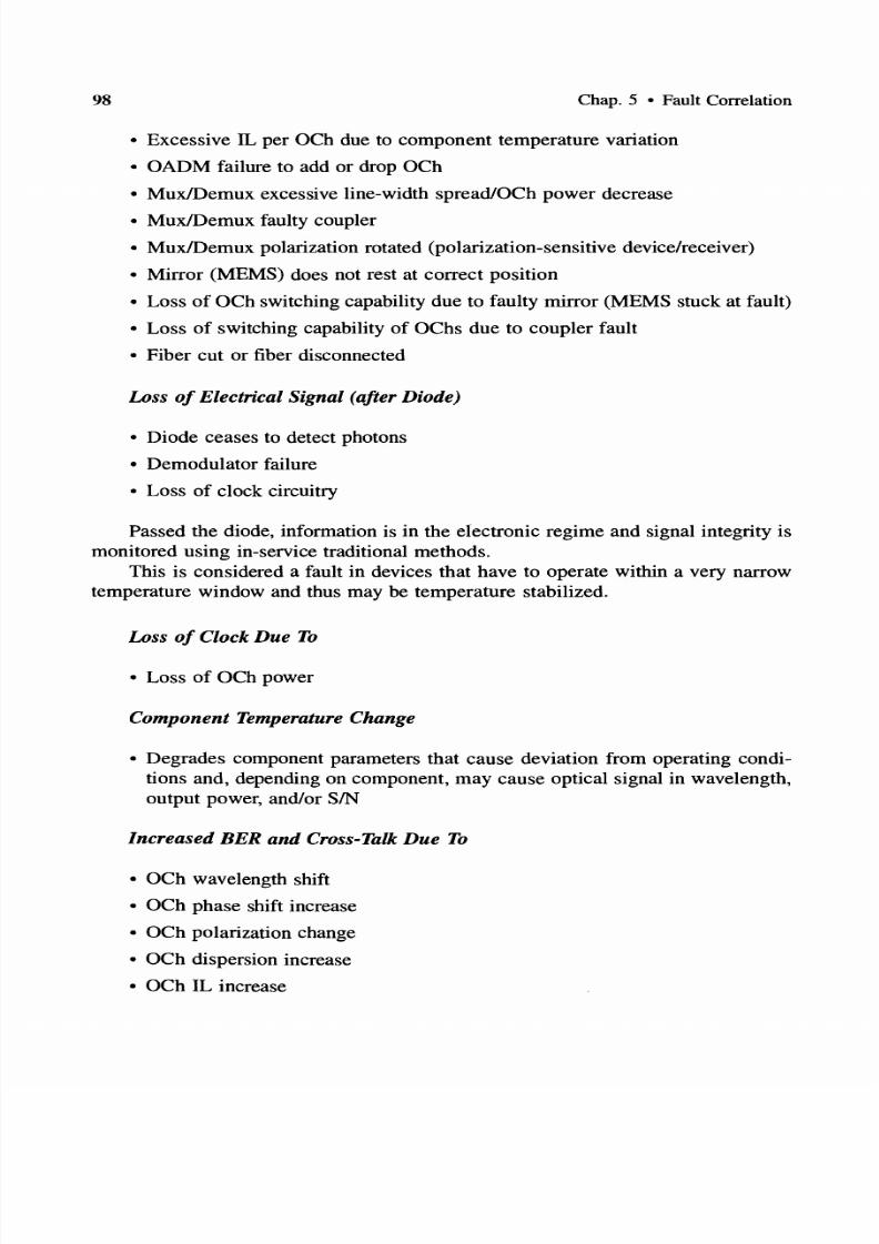
7/22/2019 Fault Detectability in DWDM - Toward Higher Signal Quality & System Reliability
http://slidepdf.com/reader/full/fault-detectability-in-dwdm-toward-higher-signal-quality-system-reliability 113/169
98 Chap. 5 • Fault Correlation
• Excessive IL per OCh due to component temperature variation
• OADM failure to add or drop OCh
• Mux/Demux excessive line-width spread/OCh power decrease
• Mux/Demux faulty coupler
• Mux/Demux polarization rotated (polarization-sensitive device/receiver)
• Mirror (MEMS) does not rest at correct position
• Loss of OCh switching capability due to faulty mirror (MEMS stuck at fault)
• Loss of switching capability of OChs due to coupler fault
• Fiber cut or fiber disconnected
Loss of Electrical Signal after Diode)
• Diode ceases to detect photons
• Demodulator failure
• Loss of clock circuitry
Passed the diode, information is in the electronic regime and signal integrity is
monitored using in-service traditional methods.
This is considered a fault in devices that have to operate within a very narrow
temperature window and thus may be temperature stabilized.
Loss of Clock Due To
• Loss of OCh power
Component Temperature Change
• Degrades component parameters that cause deviation from operating condi
tions and, depending on component, may cause optical signal in wavelength,
output power, and/or SIN
Increased BER and Cross-Talk Due To
• OCh wavelength shift
• OCh phase shift increase
• OCh polarization change
• OCh dispersion increase
• OCh IL increase

7/22/2019 Fault Detectability in DWDM - Toward Higher Signal Quality & System Reliability
http://slidepdf.com/reader/full/fault-detectability-in-dwdm-toward-higher-signal-quality-system-reliability 114/169
Sec. 5.2 • Correlation of Faults and Component Parameter Changes 99
• Launched optical power decrease
• Received optical power decrease
• Line-width broadening [due to group delay (GD), differential GD (DGD),
PMD, or chromatic dispersion (CD)]
• Line-width broadening (due to OA, Mux/Demux, filter)
• Line-width broadening due to laser temperature
• Directional coupler parametric changes
• Excessive dispersion accumulation
• Faulty mirror (MEMS stuck at faulty position)
• Mirror (MEMS) does not rest at correct position
• Mirror (MEMS) vibrations
• Laser wavelength driftlbroadening due to temperature or tunability
• Mux/Demux Adiscrimination disabled
• Mux/Demux polarization change (polarization-sensitive device/receiver)
• Phase shift by Mux/Demux due to temperature increase
• IL per OCh by Mux/Demux due to temperature increase
• OFA high power causes nonlinearities on certain As
• OFA pump power degrades
• OFA pump inoperable
• OFA pump wavelength drift (gain degradation of certain S
• OFA coupler malfunctioning
• Increased ASE noise due to OFA
• Increased cumulative ASE• OFA gain of an OCh decreases more than others due to misequalization
• Amplification gain of OFA or SOA decrease
• PDL increase (due to SOA temperature increase)
• SOA coupling inefficiency
• SOA gain decrease
• SOA injection current change
• Modulation depth decrease (due to laser/modulator parametric changes)
• Inefficient demodulation (causes receiver inability to discriminate Os and 1s)
• Receiving diode gain degrades (due to parametric changes)
• Receiving diode quantum efficiency degrades (due to parametric change)

7/22/2019 Fault Detectability in DWDM - Toward Higher Signal Quality & System Reliability
http://slidepdf.com/reader/full/fault-detectability-in-dwdm-toward-higher-signal-quality-system-reliability 115/169
100 Chap. 5 • Fault Correlation
• Filter [Fabry-Perot (FP)] parametric variations (due to temperature, stress, or
field changes)
• Passband IL (per DCh) caused by FP (due to parametric changes)
• Filter (Bragg) detuning (due to dispersion per DCh)
• Filter (Bragg) parametric variations (due to temperature or stress changes)
• Filter (ADTF) detuning (due to parametric changes)
• Filter (AOTF) detuning (due to RF shift)
• Filter (AOTF) polarization change*
• Filter (AOTF) registration mismatch (due to Doppler) frequency shift*
• Increased PDL [due to ADF filter RF power change]
• Increased PDL (due to filter parametric changes)
• Coupling loss (due to filter misalignment of polarization state)
• DCh dispersion increase (caused by temperature, stress, or field variation)
• Power amplitude of decrease (due to a component IL increase)
• Nonlinear interaction of two DChs (due to channel spacing decrease)
5.3 OPEN ISSUES NONLINE R EFFECTS
Dispersion and nonlinear phenomena impact BER and cross-talk levels. They are
not readily and directly detected. Thus, a better mechanism is needed to distinguish
among the many sources of BER and cross-talk for faster fault identification and
localization.
Self-modulation or modulation instability is a phenomenon that degrades the width
of the pulse when the center wavelength is in the anomalous dispersion regime(above the zero-dispersion wavelength). This phenomenon needs to be further un
derstood as it impacts the received BER and cross-talk.
FWM is more intense at the near end of the fiber and is expected to fade out as the
DChs are attenuated (after 20-50 km). FWM could be diminished if DChs were
synchronized. Reducing FWM improves the BER at the receiver, which effectively
may increase the fiber span. Synchronization methods need be investigated and the
improvement quantified.
ITU-T has defined center frequencies evenly spaced (100 and 50 GHz). Proposals
have been made to space them unevenly to minimize FWM. However, evenly
*Not applicable in all implementations

7/22/2019 Fault Detectability in DWDM - Toward Higher Signal Quality & System Reliability
http://slidepdf.com/reader/full/fault-detectability-in-dwdm-toward-higher-signal-quality-system-reliability 116/169
References
spaced frequencies allow for linear expansion of Oehs and better dynamic wave
length allocation and management. This needs to be further studied and understood
so that faults related to nonlinearities are minimized.
Fiber amplifiers with rare-earth dopants need to be further investigated. It would be
advantageous if a single OFA could be used for the complete spectrum 1.3-1.6 u.m.
This would also simplify failure detection mechanisms and actions.
PMD is an area that needs further investigation.
Integration of optical components (some using nonlinearities) is an emerging area
with great potential. This may impact favorably the fault analysis process.
R F R N S
[1] S. V. Kartalopoulos, Introduction to DWDM Technology: Data in a Rainbow, IEEE
Press, New York, 2000.
[2] S. V. Kartalopoulos, Understanding SONETISDH and ATM: Networks for the Next Mil
lennium, IEEE Press, New York, 1999.
[3] S. V. Kartalopoulos, Aspects in Fault Detectability, Proceedings of ACM 2000 London, Nov. 14-16, 2000, to be published.
[4] B. Furht, Handbook of Internet and Multimedia: Systems and Applications, IEEE Press,
New York, 1999.
[5] L. G. Raman, Fundamentals of Telecommunications Network Management, IEEE Press,
New York, 1999.
[6] A. Borella, G. Cancellieri, and F. Chiaraluce, Wavelength Division Multiple Access Op
tical Networks, Artech House, Boston, 1998.
[7] B. T. Doshi, S. Dravida, P. Harshavardhana, O. Hauser, and Y.Wang, Optical Network
Design and Restoration, Bell Labs Tech. J., vol. 4, no. 1, 1999, pp. 58-84.
[8] S. Chatterjee and S. Pawlowski, All-Optical Networks, Commun. ACM vol. 47, no.
6, 1999, pp. 74-83.
[9] S. V. Kartalopoulos, A Manhattan Fiber Distributed Data Interface Architecture, in
Proceedings of IEEE Globecom 90, San Diego, Dec. 2-5, 1990.
[10] S. V. Kartalopoulos, Disaster Avoidance in the Manhattan Fiber Distributed Data
Interface Network, in Proceedings of IEEE Globecom 93 Houston, TX, Dec. 2,
1993.
[11] S. R. Johnson and V. L. Nichols, Advanced Optical Networking-Lucent s MONET
Network Elements, Bell Labs Tech. J., vol. 4, no. 1, 1999, pp. 145-162.[12] Y. Chen, M. T. Fatehi, H. J. LaRoche, J. Z. Larsen, and B. L. Nelson, Metro Optical
Networking, Bell Labs Tech. J., vol. 4, no. 1, 1999, pp. 163-186.
[13] A. R. Chraplyvy, High-Capacity Lightwave Transmission Experiments, Bel l Labs
Tech. J., vol. 4, no. 1, 1999, pp. 230-245.

7/22/2019 Fault Detectability in DWDM - Toward Higher Signal Quality & System Reliability
http://slidepdf.com/reader/full/fault-detectability-in-dwdm-toward-higher-signal-quality-system-reliability 117/169
2 Chap. 5 • Fault Correlation
[14] D. B. Buchholz et aI., Broadband Fiber Access: A Fiber-to-the-Customer Access Ar
chitecture, Bell Labs ech J., vol. 4, no. 1, 1999, pp. 282-299.
[15] G. C. Wilson et aI., FiberVista: An FfTH or FfTC SystemDelivering Broadband Dataand CATV Services, Bell Labs ech J., vol. 4, no. 1, 1999, pp. 300-322.
[16] M. Berger et aI., Pan-European Optical Networking Using Wavelength Division Mul
tiplexing, IEEE Commun. Mag., vol. 35, no. 4, 1997, pp. 82-88.
[17] B. Fabianek, K. Fitchew, S. Myken, and A. Houghton, Optical Network Research and
Development in European Community Programs: From RACE to ACTS, IEEE Com
mun. Mag., vol. 35, no. 4, 1997, pp. 50-56.
[18] D. Cotter, J. K. Leek, and D. D. Marcenac. Ultra-High-Bit-Rate Networking: From the
Transcontinental Backbone to the Desktop, IEEE Commun Mag., vol. 35, no. 4, 1997,
pp.90-96.
[19] S. F. Midkiff, Fiber Optic Backbone Boosts Local-Area Networks, IEEE Circuits De
vices Mag., vol. 8, no. 1, 1992, pp. 17-21.
[20] E. Traupman, P. O Connell, G. Minnis, M. Jadoul, and H. Mario, The Evolution of the
Existing Infrastructure, IEEE Commun. Mag., vol. 37, no. 6, 1999, pp. 134-139.
[21] A. G. Malis, Reconstructing Transmission Networks Using ATM and DWDM, IEEE
Commun. Mag., vol. 37, no. 6, 1999, pp. 140-145.
[22] R. K. Snelling, Bringing Fiber to the Home, IEEE Circuits Devices Mag., vol. 7, no.
1, 1991, pp. 23-25.
[23] H. Toba and K. Nosu, Optical Frequency Division Multiplexing Systems: Review of
Key Technologies and Applications, IEICE Trans. Commun., vol. E75, no. 4, 1992, pp.
243-255.
[24] O. E. DeLange, Wide-Band Optical Communication Systems: Part II-Frequency
Division-Multiplexing, Proc. IEEE, vol. 58, no. 10, 1970, pp. 1683-1690.
[25] D. K. Hunter et al., WASPNET: A Wavelength Switched Packet Network, IEEE Com
mun. Mag., vol. 37, no. 3, 1999, pp. 120-129.
[26] E. Modiano, WDM-Based Packet Network, IEEE Commun. Mag., vol. 37, no. 3,
1999, pp. 130-135.
[27] H. Kobrinski, R. M. Bulley, M. S. Goodman, M. P.Vecchi, and C. A. Bracket, Demon
stration of High Capacity in the LAMBDANETArchitecture: A Multi-Wavelength Op
tical Network, Electron. Lett., vol. 23, 1987, pp. 303-306.
[28] R. Glance, K. Pollock, C. A. Burrus, B. L. Kasper, G. Eisenstein, and L. W. Stulz,
Densely Spaced WDM Coherent Optical Star Network, Electron. Lett., vol. 23, no.
17, 1987,pp. 875-876.
[29] N. Takato et al., 128-Channel Polarization-Insensitive Frequency-Selection-Switch Us
ing High-SilicaWaveguides on Si, IEEE Photon. Technol. Lett., vol. 2, no. 6, 1990, pp.
441-443.
[30] Y-K. M. Lin, D. Spears, and M. Yin, Fiber-Based Local Access Network Architec
tures, IEEE Commun. Mag., Oct. 1989, pp. 64-73.
[31] R. A. Linke, Optical Heterodyne Communications Systems, IEEE Commun. Mag.,
Oct. 1989, pp. 36-41.

7/22/2019 Fault Detectability in DWDM - Toward Higher Signal Quality & System Reliability
http://slidepdf.com/reader/full/fault-detectability-in-dwdm-toward-higher-signal-quality-system-reliability 118/169
Standards
ST ND RDS
3
[1] ANSIIIEEE 812-1984, Definition of Terms Relating to Fiber Optics, 1984.[2] Bellcore GR-1377, SONET OC-192 Transport Systems Generic Criteria, Issue 3,
Aug. 1996.
[3] IEC Publication 60825-1, Safety of Laser Products-Part 1: Equipment Classification,
Requirements and User s Guide, 1993.
[4] IEC Publication 60825-2, Safety of Laser Products-Part 2: Safety of Optical Fibre
Communication Systems, 1998.
[5] IEC Publication 61280-2-1, Fibre Optic Communication Subsystem Basic Test Proce
dures; Part 2: Test Procedures for Digital Systems; Section I-Receiver Sensitivity and
Overload Measurement, 1998.[6] IEC Publication 61280-2-2, Fibre Optic Communication Subsystem Basic Test Proce
dures; Part 2: Test Procedures for Digital Systems; Section 2-0ptical Eye Pattern,
Waveform and Extinction Ratio Measurement, 1998.
[7] ITU-T Recommendation G.650, Definition and Test Methods for the Relevant Pa
rameters of Single-Mode Fibres, 1996.
[8] ITU-T Recommendation G.652, Characteristics of a Single-Mode Optical Fiber Ca
ble, Apr. 1997.
[9] ITU-T Recommendation G.653, Characteristics of a Dispersion-Shifted Single-Mode
Optical Fiber Cable, Apr. 1997.[10] ITU-T Recommendation G.655, Characteristics of a Non-Zero Dispersion-Shifted Sin
gle-Mode Optical Fiber Cable, Oct. 1996.
[11] ITU-T Recommendation G.661, Definition and Test Methods for the Relevant Generic
Parameters of Optical Fiber Amplifiers, Nov. 1996.
[12] ITU-T Recommendation G.662, Generic Characteristics of Optical Fiber Amplifier
Devices and Sub-Systems, July 1995.
[13] ITU-T Recommendation G.663, Application Related Aspects of Optical Fiber Ampli
fier Devices and Sub-Systems, July 1995.
[14] ITU-T Draft Recommendation G.664, General Automatic Power Shut-Down Procedure for Optical Transport Systems, Oct. 1998.
[15] ITU-T Recommendation G.671, r a n s m i ~ i o n Characteristics of Passive Optical Com
ponents, Nov. 1996.
[16] lTV-T Recommendation G.681, Functional Characteristics of Interoffice and Long
Haul Line Systems Using Optical Amplifiers, Including Optical Multiplexers, June
1986.
[17] ITU-T Draft Recommendation G.691, Optical Interfaces for Single Channel SDH Sys
tems with Optical Amplifiers, and STM-64 Systems, Oct. 1998.
[18] ITU-T Draft Recommendation G.692, Optical Interfaces for Multi-Channel Systemswith Optical Amplifiers, Oct. 1998.
[19] ITU-T Recommendation G.707, Network Node Interface for the Synchronous Digital
Hierarchy, 1996.
7/22/2019 Fault Detectability in DWDM - Toward Higher Signal Quality & System Reliability
http://slidepdf.com/reader/full/fault-detectability-in-dwdm-toward-higher-signal-quality-system-reliability 119/169
4 Chap. 5 • Fault Correlation
[20] ITU-T Draft Recommendation G.709, Network Node Interface for the Optical Trans
port Network (OTN), Oct. 1998.
[21] ITU-T Draft Recommendation G.798, Characteristics of Optical Transport Networks(OTN) Equipment Functional Blocks, Oct. 1998.
[22] ITU-T Recommendation G.805, Generic Functional Architecture of Transport Net
works, Oct. 1998.
[23] ITU-T Recommendation G.821, Error Performance of an International Digital Con
nection Operating at a Bit Rate below the Primary Rate and Forming Part of an Inte
grated Services Digital Network, Aug. 1996.
[24] ITU-T Recommendation G.826, Error Performance Parameters and Objectives for In
ternational, Constant Bit Rate Digital Paths at or above the Primary Rate, Feb. 1999.
[25] ITU-T Recommendation G.828, Error Performance Parameters and Objectives for International, Constant Bit Rate Synchronous Digital Paths, Feb. 2000.
[26] ITU-T Draft Recommendation G.871, Framework for Optical Networking Recom
mendations, Oct. 1998.
[27] ITU-T Draft Recommendation G.872, Architecture of Optical Transport Networks,
Oct. 1998.
[28] ITU-T Draft Recommendation G.873, Optical Transport Network Requirements, Oct.
1998.
[29] ITU-T Draft Recommendation G.874, Management Aspects of the Optical Transport
Network Element, Oct. 1998.[30] ITU-T Draft Recommendation G.875, Optical Transport Network Management Infor
mation Model for the Network Element View, Oct. 1998.
[31] ITU-T Recommendation G.911, Parameters and Calculation Methodologies for Reli
ability and Availability of Fibre Optic Systems, 1993.
[32] ITU-T Recommendation G.955, Digital Line Systems Based on the 1544 kbit/s and
the 2048 kbit/s Hierarchy on Optical Fibre Cables, 1993.
[33] ITU-T Recommendation G.957, Optical Interfaces for Equipments and Systems Re
lating to the Synchronous Digital Hierarchy, 1995.
[34] ITU-T Recommendation G.958, Digital Line Systems Based on the Synchronous Digital Hierarchy for Use on Optical Fibre Cables, 1994.
[35] ITU-T Draft Recommendation G.959, Optical Networking Physical Layer Interfaces,
Feb. 1999.
[36] Telcordia GR-253, Synchronous Optical Network (SONET) Transport Systems: Com
mon Generic Criteria, Issue 2, Dec. 1995.
[37] Telcordia TR-NWT-233, Digital Cross Connect System, Nov. 1992.
[38] Telcordia TR-NWT-917, Regenerator, Oct. 1990.

7/22/2019 Fault Detectability in DWDM - Toward Higher Signal Quality & System Reliability
http://slidepdf.com/reader/full/fault-detectability-in-dwdm-toward-higher-signal-quality-system-reliability 120/169
CHAPTER 6
TOWARD DWDM
FAULT MANAGEMENT
AND CURRENT ISSUES
6.1 INTRODUCTION
DWDM is a technology that promises to increase the bandwidth per fiber at in
credible levels as the bit rate and the number of wavelengths keep increasing.
DWDM systems and networks are engineered to be applicable in long-haul appli
cations, in metropolitan and local area networks, as well as in access networks. Cur
rently, systems with few 6-8) or many (40-160) wavelengths are reality, and at
2.5-40 Gbps per optical channel they transport an amazing aggregate bandwidth up
to several Tbps per fiber.
DWDM technology promises long fiber spans (100 km or more) without am
plification. The significance of this is clear if, for example, one considers that a
SONET repeater may cost thousands of dollars per fiber in addition to maintenance
cost. Transmitting without amplification more bandwidth and more wavelengths
over longer distances is a news item that certainly does not go unnoticed.
Because of the high aggregate bandwidth and the many innovations that go in
a multiwavelength optical network, DWDM networks must have the capability todetect faults (e.g., broken fiber, faulty port unit, inoperable node, malfuntioning
components). In addition, they must have the ability to isolate and locate a fault
and quickly take a remedial action, either autonomously or via network fault man
agement. The final objective is to offer continuous transmission (service) or ser
vice with the minimum disruption possible and with the maximum quality of sig
nal. One of the outstanding issues that network architects have to answer is, when
a fault is fixed, does the network return to the previous state quickly or does it con
tinue to remain at that same state until another fault is encountered? This and many
other questions can be best addressed if, in addition to standards, software, andmanagement, there is a comprehensive knowledge of the DWDM optical compo
nents and their failure mechanisms.
DWDM is a technology that depends heavily on optical components (Figure
6.1), many of which are state of the art. Research continues to innovate and de-
105

7/22/2019 Fault Detectability in DWDM - Toward Higher Signal Quality & System Reliability
http://slidepdf.com/reader/full/fault-detectability-in-dwdm-toward-higher-signal-quality-system-reliability 121/169
106 Chap. 6 • Toward DWDM Fault Management and Current Issues
LD = Laser Diode o = hotodector: :
Figure 6.1 A DWDM point-to-point with many of the key optical components.
velop new and better performing optical materials and components, to integrate
more than one function in a single component, and to make components more
compact and at lower cost. Amplifiers, switches, multiplexers, filters, signal con
ditioners, transmitter arrays, receiver arrays, and miniature interconnecting devices
are among them. In addition, standard transport protocols and network manage
ment standards for interoperability are necessary to detect faults and errors in traf
fic flow, to initiate consequent actions, to correlate defects, and to report failures.The goal is to develop compatible systems conforming to standards and a reliable
system and network that assures high-quality signal and service and minimal
downtime. If old traditional voice services can demand downtime as short as min
utes per year, then how short should the downtime be considering bandwidths of
terabits per second?
In communications networks, a defect and an anomaly are clearly defined.
Their definition however varies from technology to technology, and a complete dis
cussion on this topic is beyond our scope. Therefore, we encourage the reader to
consult the appropriate Fault management document. For example, a defect in ATMmay be due to loss of signal (LOS) or to a transmission path alarm indication sig
nal (TP-AIS), whereas in SDH an anomaly may be due to error blocks (EBs) as in
dicated by the error detection code (EDC) and a fault may be due to a broken fiber.
Here, it suffices to say that many faults that affect the optical signal translate into
defects. Hence, reliable and fast fault remedial mechanisms translate into defect
avoidance, increased traffic availability of the network as well as traffic perfor
mance against network link degradations. Figure 6.2 illustrates the case of a dual
ring architecture whereby when a broken fiber is detected the ring automatically re
configures itself for continuous service.The following attempts to identify and describe some current issues and areas
of intense research and also to summarize the work in this book. Areas not men
tioned are not minimized; we merely cannot mention them all.

7/22/2019 Fault Detectability in DWDM - Toward Higher Signal Quality & System Reliability
http://slidepdf.com/reader/full/fault-detectability-in-dwdm-toward-higher-signal-quality-system-reliability 122/169
Sec . 6.2 • Toward Fault Management 107
....Primary ring
.•.... .... econd ry ring
OADM
Figure 6.2 A DWDM dual-ring network that is able to detect faults and to u-turn traffic via an optical
cross-connect, thus avoiding the faulty link.
6.2 TOWARD FAULT MANAGEMENT
Performance monitoring encompasses all functions and operations that monitor the
level or quality of the signal manifested by the rate of errored bits (BER) as well
as the time density of errored bits (e.g., errored bit seconds). As already described,
the quality of the optical signal in DWDM may be degraded by one or more fac
tors (linear and nonlinear interactions as well as component degradations/failures)
as detailed herein. Performance parameters, by and large at the physical layer, are
continuously monitored, and any deviations from the accepted value are reported to
the system performance manager. Although spurious noise conditions (e.g., bursts
of noise) may affect the signal quality and performance sporadically, performancemay also be affected persistently by a faulty condition in one or more optical com
ponents on the signal path (e.g., filter, amplifier, laser). Such faults then become the
object of fault management.

7/22/2019 Fault Detectability in DWDM - Toward Higher Signal Quality & System Reliability
http://slidepdf.com/reader/full/fault-detectability-in-dwdm-toward-higher-signal-quality-system-reliability 123/169
108 Chap. 6 • Toward DWDM Fault Management and Current Issues
Fault management within a network element (NE) encompasses all these func
tions and operations that aim at fault detection, fault correlation, fault localization
and isolation, service restoration, and fault remedial actions. Service restoration isthe ultimate goal, and fault detection is the first step to accomplish that. When a
network element detects a failure condition, it generates a fault notification. A fault
notification may cause an alarm state. Since a fault may affect the client's service,
it is critical that service is restored in real time. This may be accomplished by ei
ther restoring service by finding an alternate path or isolating the fault and replac
ing the faulty circuit with a functional one.
6.2.1 The Network Level
Finding an alternate path is a function at the network level and is typically implemented by executing routing algorithms and communications protocols. In this case,
it is implied that the optical network has available bandwidth, reserve protection
paths, and supports restoration functions on both the architectural and algorithmic
levels. In addition, the path termination endpoints are equipped with fault-detecting
mechanisms. These mechanisms have filtering criteria, and reports are sent to the
NE fault management system. The latter identifies the fault types, correlates faults,
classifies the fault severity level, issues possible alarms, archives the fault attributes,
and communicates the results to a network fault management application whose
task it is to isolate the fault and trigger consequent remedial actions.Equipment failure in the upstream direction may affect the transmission signal
in the downstream direction, and a single failure may cause many fault notifications.
Similarly, a single failure may involve many signal paths (e.g., a fiber cut in DWDM
transmission), again each causing a flood of messages. These are fault management
issues that need to be addressed so that the network is not flooded with unneces
sary messages.
In summary, two types of fault information are of importance, fault type and
fault location (FT FL). Typically, there has been allocated overhead bandwidth
for reporting fault status to all NEs on the path, line, and/or section , if we follow the SONET/SDH nomenclature. In the optical transport network (OTN), more
layers are being defined, yet the OTN, like the SONET/SDH defines a synchronous
optical mechanism to transport payload of many clients that are contained in the
payload section of an OTN frame. One of the major differences of the OTN frame
is a forward error correction (FEC) code that has been included to detect and cor
rect errors. Thus, because of the added FEC, the OTN optical signal becomes more
resilient to many optical noise sources. Standards are currently drafted to define the
exact meaning, allocation, and function of overhead for FT FL, which is designed
to inform NEs in both upstream and downstream directions.
6.2.2 The NE Level
Replacing a faulty circuit is implimented locally by the NE. In this case, it is im
plied that the NE has been equipped with protection circuitry to replace the faulty

7/22/2019 Fault Detectability in DWDM - Toward Higher Signal Quality & System Reliability
http://slidepdf.com/reader/full/fault-detectability-in-dwdm-toward-higher-signal-quality-system-reliability 124/169
Sec. 6.3 • Current Issues 9
circuit. The NE has fault detection mechanisms with filtering criteria that identify
various fault types and issue reports to a NE fault management system. The latter
correlates faults, classifies the fault severity level, generates fault notification messages that trigger remedial actions, issues possible alarms, and archives the fault
type and location. Here, reports cause the (non-real-time) eventual replacement of
the faulty circuit by personnel. As in the previous case, a single failure may involve
many signal paths (e.g., a DWDM fiber cut) that may cause a flood of messages to
the NE processor.
6 3 CURRENT ISSUES
6 3 1 Optical Supermaterials
Artificial new solid-state optical materials with unusual characteristics are in the ex
perimental stage. Their characteristics are based on extremely high values of the in
dex of refraction, polarization, and switching properties when a varying field is ap
plied. Other artificially induced material properties are based on highly dynamic
optical energy absorption and coherent photoluminesence over a wide spectrum
range that covers the C- and L-bands or beyond.
In addition, researchers are experimenting with organic compounds that can absorb one wavelength and emit another (for wavelength conversion) or they can ab
sorb a wavelength and emit it back when it is stimulated (optical memory).
6 3 2 Integration
Optical integration will also be the next step in the evolution of optical devices.
Integration combined with sophisticated packaging will yield devices with complex
functionality that could perform optical signal processing with no need to convert
the optical signal to electrical. It will not be long when optical devices will follow
a similar path evolution as the transistor and the intergrated devices did. A few yearsago it was a dream to approach a million transistors in a chip. Today, this dream is
past tense and unimpressive.
6 3 3 Lasers and Receivers
Low-cost lasers are important in many applications. Some researchers are even ex
perimenting with organic compounds to create inexpensive high-density plastic
lasers and other components.
Development of high-power tunable inexpensive lasers and laser arrays with
narrow line width and sufficient optical power for DWDM applications is anotheractivity.
A similar activity is to produce tunable receivers and receiver arrays at low
cost. In this venue, some have succeeded in generating hundreds of wavelength
channels with a single laser.

7/22/2019 Fault Detectability in DWDM - Toward Higher Signal Quality & System Reliability
http://slidepdf.com/reader/full/fault-detectability-in-dwdm-toward-higher-signal-quality-system-reliability 125/169
Chap. 6 • Toward DWDM Fault Management and Current Issues
6 3 4 Line Coding Techniques
As the number of wavelengths per fiber increases (reaching 1000 or more), and as
the number of bits per second increases (currently 40 Gbps and increasing), the op
tical signal becomes more vulnerable to errors due to dispersion and other linear
and nonlinear phenomena. This increased vulnerability, however, should not com
promise in any way the quality of the signal; the signal must be maintained at the
acceptable and expected level despite the aggregate bandwidth benefit. This means
that signal error countermeasures must be developed to compensate for and correct
induced errors on the signal.
Such countermeasures may be based on new line coding techniques that are in
tersymbol interference (lSI) resistant, on error detection/correction mechanisms thatare able to locate and correct errors, or on a combination of both line coding and
error correction. A metric of good line coders (for 10 Gbps) is to produce an ac
ceptable eye diagram at the receiver such that the uncertainty of the state o r 0)
of the received bits is less than 1 bps/Hz. Error rates (as specified in lTV-T stan
dards) may be less than 10-12 BER.
6 3 5 Optical Cross Connect
As the number of wavelengths per fiber increases to numbers exceeding 200 and
approaching 1000, 1000 X 1000, or more optical cross-connect switching fabrics
with low insertion loss, nonblocking and fast switching optical systems are a chal
lenge. Today, there is a substantial effort to develop high-density devices with
switching matrices based on MEMS technology.
However, research continues to engineer better and faster optical switching
methods. Currently, there is research underway to develop ultrafast switching de
vices based on glasses that contain chalcogenides. Chalcogenide glasses (Ge-Se-Te)
have an index of refraction 1000 times higher than Si02 glass, an ultrafast response
time (they can switch from high nonlinear absorption to low) of less than 1 ps, a
low linear loss and a low nonlinear loss and a high figure of merit (FOM), on
the order of 20.
6 3 6 Optical Add Drop Multiplexers
Low-cost optical add-drop multiplexers are key components in optical networks.
OADM devices allow to drop off and add wavelengths selectively and pass through
all other wavelengths. Low-loss and low-cost OADM devices that add/drop groups
of wavelengths on a selective basis are another challenge.
The day the fiber will be connected with the desktop computer and multimedia devices is not too far. The bit rate to the home at 64 kbps in the 1960s will be
higher than 1.5-2 Mbps in the 2000s (in some cases it may be up to 50 Mbps).
These applications will demand extremely low cost and reliable optical devices
(transmitters, receivers, and filters).
7/22/2019 Fault Detectability in DWDM - Toward Higher Signal Quality & System Reliability
http://slidepdf.com/reader/full/fault-detectability-in-dwdm-toward-higher-signal-quality-system-reliability 126/169
Sec. 6.3 • Current Issues
6 3 7 Optical Memories and Variable Delay Lines
Optical delay lines consist of fiber cut at lengths that, based on travel time of light
in the fiber medium, can delay light by a fixed amount of time. This principle is al
ready used in monolithic interferometers. However, compact optical devices that
can store a light pulse of as long as it is needed would construct a true optical mem
ory and a controllable delay. Such devices would be used to treat light pulses in a
similar manner as electronic pulses and construct optical integrated subsystems with
time-division as well as computation properties.
6 3 8 Nonintrusive Optical Monitoring
Nonintrusive optical signal monitoring, although difficult to perform, is very important. The optical signal must be monitored for power, noise, eye closure
(enough power to be detected by the receiver), wavelength accuracy, and line width.
In addition, if a system carries supervisory information, including telemetry, over
an optical channel, then this channel needs to be monitored and either be terminated
or passed transparently. In general, nonintrusive optical monitoring reduces the
amount of optoelectronics, reduces latency, and increases reliability.
6 3 9 DWDM System Dynamic Reconfigurability
System dynamic reconfigurability implies wavelength and bandwidth managementas well as fast tunable optical devices (lasers, receivers, filters, and optical cross
connects).
6 3 10 Optical Backplanes
The incoming optical signal at a port is monitored and the optical signal is directly
coupled to an optical backplane that routes the signals to another unit of the sys
tem, such as an optical cross-connect fabric. Optical backplanes provide a cost
effective and compact solution.
6 3 11 Fault Management Standards
Currently, standards for different layers of the optical network have been adopted,
others are in the draft phase, and others in the proposal phase. As DWDM evolves,
new standards proposals that address emerging issues on all aspects of DWDM sys
tems, networking, and management are expected. However, fault management
means different things to different networks and topologies. Clearly, fault manage
ment in a metropolitan application cannot be the same as that in a long-haul trans
port network. Fault management in low-bit-rate applications (e.g., 622 Mbps cannot be the same with that of a very high bit rate (e.g., 40 Gbps). And fault
management cannot be the same in voice and in Internet supporting networks.
Another issue in fault management is self-managed networks (networks that do
not require an external operating system to reconfigure the network for network sur-

7/22/2019 Fault Detectability in DWDM - Toward Higher Signal Quality & System Reliability
http://slidepdf.com/reader/full/fault-detectability-in-dwdm-toward-higher-signal-quality-system-reliability 127/169
2 Chap. 6 • Toward DWDM Fault Management and Current Issues
vivability and uninterrupted service). In this case, which topologies are prevalent to
self-management? How is network reliability and availability monitored from a cen
tralized location? And along the same lines, there are questions related to scalability and flexibility of the network, as well as to provisioning and to billing.
6 3 12 Network Issues
DWDM technology in optical networks is new ground, and thus many issues not
addressed before are emerging. Currently, there is a vast amount of work in progress
to resolve these issues. Some examples are as follows:
• Are all nodes in the DWDM network optically transparent or are they opaque?
• If they are transparent, then how do we establish end-to-end (from opticalsource to destination) wavelength connectivity?
• How do we determine the optimum number of optical components on the
end-to-end optical connection (the number of optical components may not be
the same from one end to the other) throughout the network?
• How do we rework existing systems and networks to be compatible or inter
operable with the new ones?
• How do we perform performance monitoring (PM) in the optical regime?
• What are the rules and the mechanisms for fault detection, fault avoidance,and fault restoration on the optical node level, the optical network level, the
fiber level, and the wavelength level?
• What are the rules and the mechanisms for DWDM network survivability?
• How do we configure the system/network (locally versus remotely)?
• How do we implement a supervisory channel (in-band versus out-of-band or
over a separate optical channel)?
• How do we assure service reliability, service integrity, and quality of signal
as well as quality of service (QoS) in a DWDM network with the same do
main and across different domains?
• How do we assure that different network operators observe the same rules?
• What are the mechanisms for optical network management?
• How do we transport over the same DWDM network a variety of services
[Internet Protocol (IP), SONET/SDH asynchronous transfer mode (ATM),
Ethernet-type, other]?
• How do we assign or reassign wavelengths across a DWDM optical network
in the same domain or across different domains?
• How do we assure security of network and of data?
• As DWDM systems are further deployed and evolve, how do we cope with
new emerging issues?

7/22/2019 Fault Detectability in DWDM - Toward Higher Signal Quality & System Reliability
http://slidepdf.com/reader/full/fault-detectability-in-dwdm-toward-higher-signal-quality-system-reliability 128/169
Sec. 6.4 • Engineering DWDM Systems: Conclusion 113
• When a fault is detected in the traffic flow, what is the actual scenario for in
serting FDI (forward defect indicator) and AIS (alarm indication signal) to
suppress numerous alarms in the downstream of the fault location? Or shouldthere be another mechanism? And, should there be a forward and a backward
fault location report? Or, do we need a fault-type indicator and perhaps a fault
cause indicator? And should we have an automatic power shutdown?
• What are the advantages of EDC (error detection correction) codes in the op
tical signal?
• How much can we adopt/modify from the SONET/SDH networks and what
do we have to add to the IP? How can we use from existing protocols what
perform best and modify the ones that do not? How can we converge to a
unified standard that satisfies data, voice, video, and multimedia services?
6.3.13 paque Systems
DWDM technology increases the aggregate bandwidth in a fiber, and large systems
terminate many fibers. Thus, the aggregate system bandwidth is the sum of the ag
gregate bandwidth of each fiber. For example, a system with 10 fibers, 40 wave
lengths/fiber, and 2.5 Gbps/wavelength has an aggregate bandwidth of 1 Tbps.
Presently, an all-optical switching system with a capacity of terabits per second is
dominated by optical device cost and by ultrafast electronic devices for clock recovery, signal equalization, framing, synchronization, and switching. Thus, cur
rently, systems at such bandwidth levels are by and large electro-optical (opaque),
that is, the system itself is electronic and the interfaces and transmission medium is
optical.
6.4 ENGINEERING DWDM SYSTEMS: CONCLUSION
To summarize, the design of DWDM systems requires attention to a number of keyissues. Not including cost, the following key parameters influence the design of a
system and a network (not listed in priority order):
• Nominal center frequencies (wavelengths)
• Channel capacity
• Channel width
• Channel spacing or channel separation
• Channel bit rate and modulation
• Multichannel frequency stabilization
• Channel performance
• Channel dispersion

7/22/2019 Fault Detectability in DWDM - Toward Higher Signal Quality & System Reliability
http://slidepdf.com/reader/full/fault-detectability-in-dwdm-toward-higher-signal-quality-system-reliability 129/169
4 Chap. 6 • Toward DWDM Fault Management and Current Issues
• Polarizations issues
• Power launched
• Power received
• Optical amplification
• Fiber type used as the transmission medium
• Optical power budget
• Fault detection and fault recovery
• Fault management
• Quality of the signal• Quality of the service
• Type of services supported
• Service protection and uninterrupted service offering
• Aggregate bandwidth management
• Protocol used to transport supported services
• Protocol for network management
• Network reliability
• Network protection and survivability
• Network scalability and flexibility
• System and network reconfigurability
• Supervisory channels and protocols
• Wavelength management
• Interoperability
• Interdomain compatibility
• Supervisory channel(s); in-band and out-of-band
R F R N S
[1] S. V. Kartalopoulos, Introduction to DWDM Technology: Data in a Rainbow IEEE
Press, New York, 2000.
[2] S. V.Kartalopoulos, Understanding SONETISDH and ATM: Communications Networks
for the Next Millennium IEEE Press, New York, 1999.
[3] S. V. Kartalopoulos, Aspects in Fault Detectability, Proceedings ofACM 2000 Lon
don, Nov. 14-16, 2000, to be published.
[4] R. Ramaswami and K. N. Sivarajan, Optical Networks Morgan Kaufmann, San Fran
cisco, CA, 1998.

7/22/2019 Fault Detectability in DWDM - Toward Higher Signal Quality & System Reliability
http://slidepdf.com/reader/full/fault-detectability-in-dwdm-toward-higher-signal-quality-system-reliability 130/169
References 5
[5] B. Mukherjee, Optical Communication Networks McGraw-Hill, New York, 1997.
[6] I. P. Kaminow, Ed., and T. L. Koch, Ed., Optical Fiber Communications IlIA and Op
tical Fiber Communications IIIB Academic, New York, 1997.[7] E. Traupman, P. O'Connell, G. Minnis, M. Jadoul, and H. Mario, The Evolution of the
Existing Infrastructure, IEEE Commun. Mag. vol. 37, no. 6, 1999, pp. 134-139.
[8] A. G. Malis, Reconstructing Transmission Networks Using ATM and DWDM, IEEE
Commun. Mag. vol. 37, no. 6, 1999, pp. 140-145.
[9] T-H Wu, Fiber Network Service Survivability Artech House, Boston, 1992.
[10] L. Boivin, M. C. Nuss, W. H. Knox, and J. B. Stark, 206-Channel Chirped-Pulse Wave
length-Division Multiplexed Transmitter, Electron. Lett. vol. 33, no. 10, 1997, pp.
827-828.
[11] J. M. Simmons et aI., Optical Crossconnects of Reduced Complexity for WDM Networks with Bidirectional Symmetry, IEEE Photon. Technol. Lett. vol. 10, no. 6, 1998,
pp. 819-821.
[12] E. A. De Souza et aI., Wavelength-Division Multiplexing with Femtosecond Pulses,
Opt. Lett. vol. 20, no. 10, 1995, pp. 1166-1168.
[13] S. V. Kartalopoulos, An Associative RAM-Based CAM and Its Application to Broad
Band Communications Systems, IEEE Trans. Neural Networks vol. 9, no. 5, 1998, pp.
1036-1041.
[14] S. V. Kartalopoulos, Ultra-Fast Pattern Recognition in Broadband Communications
Systems, ISPACS 98 Conference Proceedings Melbourne, Australia, Nov. 1998.
[15] S. V. Kartalopoulos, The A-Bus in Ultra-fast DWDM Systems, to be published.
[16] S. V. Kartalopoulos, Synchronization Techniques Ultra-Fast DWDM Systems: The A
bus, to be published.
[17] S. V. Kartalopoulos, Add-Drop with Ultra-fast DWDM/A-Bus, to be published.
[18] S. V. Kartalopoulos, Increasing Bandwidth Capacity in DWDM/A-Bus Systems, to be
published.
[19] S. V. Kartalopoulos, Cryptographic Techniques with Ultra-fast DWDM/A-Bus Sys
tems, to be published.
[20] C.A. Brackett, DenseWavelength Division Multiplexing Networks: Principles and Ap
plications, IEEE JSAC vol. 8, no. 6, 1990, pp. 948-964.
[21] H. Yoshimura, K-I. Sato, and N. Takachio, Future Photonic Transport Networks Based
on WDM Technologies, IEEE Commun. Mag. vol. 37, no. 2, 1999, pp. 74-81.
[22] L. H. Sahasrabuddhe and B. Mukherjee, Light-Trees: Optical Multicasting for Im
proved Performance in Wavelength-Routed Networks, IEEE Commun. Mag. vol. 37,
no. 2, 1999,pp. 67-73.
[23] M.A.Marsan, A. Bianco, E. Leonardi, A.Morabito, and F.Neri, ''All-Optical WDM Multi
Rings with Differentiated QoS, IEEE Commun. Mag. vol. 37, no. 2, 1999, pp. 58-66.
[24] Y.Pan, C. Qiao, and Y.Yang, Optical Multistage Interconnection Networks: New Chal
lenges and Approaches, IEEE Commun. Mag. vol. 37, no. 2, 1999, pp. 50-56.
[25] K. Sato, Advances in Transport Network Technologies-Photonic Networks TM and
SDH Artech House, Boston, 1996.
[26] N. Takachio and S. Ohteru, Scale of WDM Transport Network Using Different Types
of Fibers, IEEE JSAC vol. 16, no. 7, 1998, pp. 1320-1326.

7/22/2019 Fault Detectability in DWDM - Toward Higher Signal Quality & System Reliability
http://slidepdf.com/reader/full/fault-detectability-in-dwdm-toward-higher-signal-quality-system-reliability 131/169
6 Chap. 6 • Toward DWDM Fault Management and Current Issues
[27] B. Mukhergie, Optical Communications Networks McGraw-Hill, New York, 1997.
[28] P. E. Green, Jr., Fiber Optic Networks Prentice-Hall, Englewood Cliffs, NJ, 1993.
[29] M. A. Marsan et aI., Daisy: A Scalable All-Optical Packet Network with Multi-FiberRing Topology, Computer Networks ISDN Syst. vol. 30, 1998, pp. 1065-1082.
[30] I. Gidon and Y. Ofek, MetaRing-a Full-Duplex Ring with Fairness and Spatial
Reuse, IEEE Trans. Commun. vol. 41, no. 1,1993, pp. 110-120.
[31] S. Ohteru and K. Inoue, Optical Time Division Multiplexer Utilizing Modulation Sig
nal Supplied to Optical Modulation as a Reference, IEEE Photon vol. 8, no. 9, 1996,
pp. 1181-1183.
[32] J. R. Freer, Computer Communications and Networks IEEE Press, New York, 1996.
[33] R. Handel and M. N. Huber, Integrated Broadband Network Addison-Wesley, Reading,
MA, 1991.[34] R. D. Gitlin, J. F. Hayes, and S. B. Weinstein, ata Communications Principles
Plenum, New York, 1992.
[35] S. V. Kartalopoulos, A Manhattan Fiber Distributed Data Interface Architecture, in
Proceedings of IEEE Globecom 90 San Diego, Dec. 2-5, 1990.
[36] S. V. Kartalopoulos, Disaster Avoidance in the Manhattan Fiber Distributed Data In
terface Network, in Proceedings of IEEE Globecom 93 Houston, TX, Dec. 2, 1993.
[37] S. V. Kartalopoulos, A Plateau of Performance? IEEE Commun. Mag. Sept. 1992, pp.
13-14.
[38] A. E. Willner, Mining the Optical Bandwidth for a Terabit per Second, IEEE Spectrum Apr. 1997, pp. 32-41.
[39] S. V. Kartalopoulos, Understanding Neural Networks and Fuzzy Logic IEEE Press,
New York, 1995.
[40] Members of the Technical Staff, Transmission Systems fo r Communications Bell Tele
phone Laboratories, New York, 1982.
[41] J. Nellist, Understanding Telecommunications and Lightwave Systems IEEE Press,
New York, 1996.
[42] W. Y. Zhou and Y.Wu, COFDM: An Overview, IEEE Trans. Broadcasting vol. 41,
no. 1, 1995, pp. 1-8.
STANDARDS
[1] ITU-T Recommendation 0.702, Digital Hierarchy Bit Rates, 1988.
[2] ITU-T Draft Recommendation 0.691, Optical Interfaces for Single Channel SDH Sys
tems with Optical Amplifiers, and STM-64 Systems, Oct. 1998.
[3] ITU-T Draft Recommendation 0.692, Optical Interfaces for Multi-Channel Systems
with Optical Amplifiers, Oct. 1998.
[4] ITU-T Recommendation 0.707, Network Node Interface for the Synchronous Digital
Hierarchy, 1996.
[5] ITU-T Draft Recommendation G.709, Network Node Interface for the Optical Trans
port Network (OTN), Oct. 1998.
[6] ITU-T Draft Recommendation 0.798, Characteristics of Optical Transport Networks
(OTN) Equipment Functional Blocks, Oct. 1998.

7/22/2019 Fault Detectability in DWDM - Toward Higher Signal Quality & System Reliability
http://slidepdf.com/reader/full/fault-detectability-in-dwdm-toward-higher-signal-quality-system-reliability 132/169
Standards 7
[7] ITV-T Recommendation G.805, Generic Functional Architecture of Transport Net
works, Oct. 1998.
[8] ITV-T Draft Recommendation G.871, Framework for Optical Networking Recommendations, Oct. 1998.
[9] ITV-T Draft Recommendation G.872, Architecture of Optical Transport Networks,
Oct. 1998.
[10] ITV-T Draft Recommendation G.873, Optical Transport Network Requirements, Oct.
1998.
[11] ITV-T Draft Recommendation G.874, Management Aspects of the Optical Transport
Network Element, Oct. 1998.
[12] ITV-T Draft Recommendation G.875, Optical Transport Network Management Infor
mation Model for the Network Element View, Oct. 1998.[13] lTV-T Recommendation G.911, Parameters and Calculation Methodologies for Reli
ability and Availability of Fibre Optic Systems, 1993.
[14] ITV-T Recommendation G.957, Optical Interfaces for Equipments and Systems Re
lating to the Synchronous Digital Hierarchy, 1995.
[15] ITV-T Recommendation G.958, Digital Line Systems Based on the Synchronous Dig
ital Hierarchy for se on Optical Fibre Cables, 1994.
[16] ITV-T Draft Recommendation G.959, Optical Networking Physical Layer Interfaces,
Feb. 1999.
[17] Telcordia GR-253, Synchronous Optical Network (SONET) Transport Systems: Common Generic Criteria, Issue 2, Dec. 1995.

7/22/2019 Fault Detectability in DWDM - Toward Higher Signal Quality & System Reliability
http://slidepdf.com/reader/full/fault-detectability-in-dwdm-toward-higher-signal-quality-system-reliability 133/169
ACRONYMS
10BaseT
100BaseT
1000BaseT
2FSK
3R
8B/IOB
AA
AAL
ABM
ABR
AC
ACD
ACSE
ACTS
ADBF
ADC
ADM
ADPCM
ADSL
ADTS
AFIAFNOR
APR
10 Mbps over twisted pair
100 Mbps over twisted pair
1000 Mbps over twisted pair
Two-level frequency shift keying
Reshaping, retiming, and reamplifying
Eight-bit to 10-bit coding
Adaptive antenna
ATM adaptation layer
ATM buffer management
Available bit rate
Authentication counter; alternating current
Automatic call distribution system
Association control service element
Advanced Communications Technology and Services
Advanced digital beam forming
Analog-to-digital conversion
Add-drop multiplexer
Adaptive differential pulse code modulation
Asymmetric digital subscriber line
Automated digital terminal equipment system
Authority format identifierAssociation Francaise de Normalisation
Absolute frequency reference
119

7/22/2019 Fault Detectability in DWDM - Toward Higher Signal Quality & System Reliability
http://slidepdf.com/reader/full/fault-detectability-in-dwdm-toward-higher-signal-quality-system-reliability 134/169
2
AGC
AH
AIS
AID
AIX
Al
ALTS
AM
AMAC
AMF
AMI
AMPS
AN
ANSI
AON
AOTF
AP
APCAPD
APDU
APON
APS
AR
ARM
ARPA
ARQ
As
AS C
ASBC
ASE
ASK
ASP
ATM
ATU
ATU-C
ATU-R
AU
Acronyms
Automatic gain control
Applications header
Alarm indication signal; aka blue alarm
Access interface unit
Advanced interactive executive
Aluminum
Alternative Local Transmission System
Administration module; amplitude modulation
American Market Awareness and Education Committee
Asian Multimedia Forum
Alternate mark inversion
Advanced Mobile Phone Service
Access node
American National Standards Institute
All Optical Network
Acousto-optic tunable filter
Access point; adjunct processor
Adaptive predictive codingAvalanche photodetector; Access procedure-D channel
Application protocol data unit; Authentic protocol data unit
ATM-based broadband PON
Automatic protection switching
Antireflecting (coating)
Access Resource Management
Advanced Research Project Agency
Automatic repeat request
Arsenic
Alarm, surveillance, and control
Adaptive subband coding
Amplified spontaneous emission; application service element
Amplitude shift keying
Adjunct service point
Asynchronous transfer mode
ADSL transceiver unit
ATU central office
ATU remote terminal
Administrative unit
7/22/2019 Fault Detectability in DWDM - Toward Higher Signal Quality & System Reliability
http://slidepdf.com/reader/full/fault-detectability-in-dwdm-toward-higher-signal-quality-system-reliability 135/169
Acronyms
AU-AIS
AUG
AU-LOP
AU-N
AU-NDF
AU-PJE
AWG
AWGN
BAS
BB
BBE
BBER
BCC
BCCH
BCD
BCF
BDCSBDI
BDMA
BECN
BER
BFSK
BICI
BIM
BIP
BIP-8
BISDN
BITS
BLER
BLSR
BnZS
BPF
bps
BPSK
BRI
BS
Administrative unit AIS
Administrative unit group
Administrative unit loss of pointer
Administrative unit level Administrative unit new data flag
Administrative unit pointer justification event
Array waveguide grating
Additive white gaussian noise
Broadband access signaling
Broadband
Background block error
Background block error ratio
Block check character; blocked-calIs-cleared
Broadcast control channel
Binary-coded decimal; Blocked-calIs-delayed
Burst coordination function
Broadband Digital Cross-Connect SystemBackward defect indication
Band division multiple access
Backward explicit congestion notification
Bit error rate; basic encoding rules
Binary FSK
Broadband Inter-Carrier Interface
Byte-interleaved multiplexer
Bit-interleaved parity
Bit-interleaved parity 8 field
Broadband Integrated Services Digital Network
Building Integrated Timing System
Block error rate
Bidirectional line-switched ring
Bipolar n-zero substitution, n=3 6, 8
Bandpass-filter
Bits per second
Binary PSK
Basic rate interface
Burst second
121
7/22/2019 Fault Detectability in DWDM - Toward Higher Signal Quality & System Reliability
http://slidepdf.com/reader/full/fault-detectability-in-dwdm-toward-higher-signal-quality-system-reliability 136/169
122
BSHR
BSHRJ2
BSHRJ4
BSI
BSS
BTS
BV
BW
C-n
CAC
CAD
CAGR
CAM
CAP
CARIN
CAS
CBMS
CBR
CC
CCAF
CCC
CCF
CCI
CCITT
CCM
CCR
CCSN
CD
CDC
CDMA
CDPD
CDR
CDV
CDVT
CEI
CEIGD
Acronyms
Bidirectional shelf healing ring
Two-fiber bidirectional shelf healing ring
Four-fiber bidirectional shelf healing ring
British Standards Institution
Broadband Switching System; basic service set
Bit Transport System
Bipolar violation
Bandwidth
Container-level n n= 11, 12, 2, 3, 4
Connection admission control
Computer-aided design
Cumulative average growth rate
Content addressable memory; computer-aided manufacture
Carrierless amplitude phase; competitive access provider
Center for Applied Research in Information Networking
Channel-associated signaling
Computer-Based Message System
Constant bit rate
Composite clock
Call Control Agent System
Clear channel capability
Call control function
Compliant client interface
Consultative Committee International Telegraph and Telephone
(renamed lTD)
Cross-connect multiplexing
Current cell rate
Common Channel Signaling Network
Chromatic dispersion
Chromatic dispersion coefficient
Code division multiple access
Cellular digital packet data
Call detail record
Cell delay variation
Cell delay variation tolerance
Connection endpoint identifier
Channel estimation and interference generation unit

7/22/2019 Fault Detectability in DWDM - Toward Higher Signal Quality & System Reliability
http://slidepdf.com/reader/full/fault-detectability-in-dwdm-toward-higher-signal-quality-system-reliability 137/169
Acronyms
CELP
CEPT-n
CER
CES
CEU
CF
CFP
CI
CICS
CIM
CIR
CIT
CIU
CLASS
CLEC
CLIP
CLLI
CLNP
CLP
CLR
CLTP
CM
CMI
CMIP
CMISE
CMIS/P
CMOS
CNM
CNTRL
CO
CODEC
COFDM
COMSIC
COP
CORBA
CoS
COT
123
Code excited linear prediction
Conference of European Posts and Telecommunications-level n
(see El
Cell error rate
Circuit Emulation Service
Committed end user
Conventional (single-mode) fiber
Contention-free period
Congestion indicator
Customer information control subsystem
Common information model
Committed information rate
Craft interface terminal
Channel interface unit
Custom Local Area Signaling Services
Competitive local exchange carrier
Channel loading independent performance
Common language location identifier
Connectionless Network Layer Protocol
Cell loss priority
Cell loss rate
Connectionless Transport Layer Protocol
Communications module; connection management
Coded mark inversion
Common Management Information Protocol
Common Management Information Service Element
Common Management Information ServiceIProtocol
Complementary metal-oxide-semiconductor
Customer network management
Control
Central office
Coder-decoder
Coded orthogonal frequency-division multiplexing
Coherent multistage interference canceller
Connection Oriented Protocol
Common object request broker architecture
Class of service
Central office terminal

7/22/2019 Fault Detectability in DWDM - Toward Higher Signal Quality & System Reliability
http://slidepdf.com/reader/full/fault-detectability-in-dwdm-toward-higher-signal-quality-system-reliability 138/169
24
COTS
CP
CPCS
CPDU
CPE
CPFSK
CPN
CPRING
CPWDM
CRBS
CRC
CRM
CRS
CS
CSA
CSES
CSICSMD/CD
CSMF
CS-PDU
CSU
CT-2
CTD
CTI
CUCV
CVSDM
CW
CWDM
DA
DACS
DAMA
DARPA
dB
DBF
dBm
Commercial off-the-shelf technology/equipment
Customer premises; control point; connection point;
communications processor
Common part of convergence sublayer
Computer protocol data unit
Customer premises equipment
Continuous-phase FSK
Calling party s number; Customer Premises Network
Client protection ring
Chirped-pulse WDM
Cell Relay Bearer Service
Cyclic redundancy check
Cell rate margin
Cell Relay Service
Convergence sublayer
Carrier serving area
Consecutive severely errored seconds
Convergence sublayer indicatorCarrier sense multiple access/collision detection
Conventional single-mode fiber
Convergence sublayer-PDU
Channel service unit
Cordless telephone version 2
Cell transfer delay
Computer-Telephony Integration
Channel unitCoding violation
Continuous variable slope delta modulation
Continuous wave
Coarse-wavelength division multiplexer
Dispersion accommodation
Digital Access and Cross-Connect System
Demand assignment multiple access
Defense Advanced Research Projects Agency
Decibel
Digital beam forming
Decibel with 1 mW reference level
Acronyms

7/22/2019 Fault Detectability in DWDM - Toward Higher Signal Quality & System Reliability
http://slidepdf.com/reader/full/fault-detectability-in-dwdm-toward-higher-signal-quality-system-reliability 139/169
Acronyms
DBR
DC
DCB
DCC
DCE
DCF
DCME
DCN
DCOM
DCS
DDCMP
DDD
DDE
DDS
DECT
DES
DFBDFCF
DFF
DFI
DGD
DH
DHCP
DIN
DIP
DIU
DLC
DLCI
DLL
DMT
DNHR
DOA
DOP
DP
DPA
DPBX
DPCM
125
Distributed Bragg reflector
Direct current
Digital channel bank
Data country code; data communication channel; digital clear
channel
Data circuit-terminating equipment
Dispersion compensation fiber; distributed coordination function
Digital compression multiplex equipment
Data Communications Network
Distributed component object model
Digital Cross-Connect System
Digital Data Communications Message Protocol
Direct distance dialing
Dynamic data exchange
Digital Data Service
Digital European Cordless Telecommunications System
Data encryption standard
Distributed feedbackDispersion-flattened compensated fiber
Dispersion-flattened fiber
Domain format identifier
Differential group delay
Dual homing
Dynamic Host Configuration Protocol
Deutsches Institut fuer Normung EV
Dual in-line package
Digital interface unit
Digital loop carrier
Data link connection identifier
Delay-lock tracking group
Discrete multitone modulation
Dynamic nonhierarchical routing
Direction of arrival
Degree of polarization
Diverse protection
Dynamic packet assignment
Digital PBX
Differential pulse code modulation

7/22/2019 Fault Detectability in DWDM - Toward Higher Signal Quality & System Reliability
http://slidepdf.com/reader/full/fault-detectability-in-dwdm-toward-higher-signal-quality-system-reliability 140/169
126
DPDU
DPE
DPSK
DQDB
DR
DRI
DSAP
DSBSC
DS-CDMA
DSCF
DSF
DSI
DSL
DSLAM
DS-n
DSP
DS-SMFDSSS
DST
DSU
DSX-n
DTE
DTF
DTMF
DTS
DWDM
DXC
DXC 4/4
DXI
El
E3
E4
EA
EB
Acronyms
Data link PDU
Distributed processing environment
Differential PSK
Distributed queue dual bus
Digital radio; dynamical routing
Dual-ring interface
Destination service access point
Double-sideband suppressed carrier
Direct-sequence CDMA
Dispersion-shift compensated fiber; dispersion-slope compensatedfiber
Dispersion-shifted fiber
Digital speech interpolation
Digital subscriber line
Digital subscriber line access multiplexer
Digital signal level n n= 0, 1, 2, 3
Domain-specific part; digital signal processor
Dispersion-shifted single-mode fiberDirect-sequence spread spectrum
Dispersion-supported transmission
Data service unit
Digital signal cross-connect point for DS-n signals
Data terminal equipment
Dielectric thin film
Dual-tone multifrequency
Digital Termination Service
Dense wavelength-division multiplexing
Digital cross-connect
DXC with a maximum VC-4 interface and VC-4 cross-connecting
fabric
Data exchange interface
Wideband digital facility at 2.048 Mbps, also called CEPT-l
Broadband digital facility at 34.368 Mbps, also called CEPT-3
Broadband digital facility at 139.264 Mbps, also called CEPT-4
Address extension; electroabsorption
Error block

7/22/2019 Fault Detectability in DWDM - Toward Higher Signal Quality & System Reliability
http://slidepdf.com/reader/full/fault-detectability-in-dwdm-toward-higher-signal-quality-system-reliability 141/169
Acronyms
EBC
EBCDIC
EC
ECC
ECMA
ECSA
EDC
EDCC
EDFA
EDI
EFI
EFS
EIAffIA
ElM
EIR
ELANEM
EMA
EMAC
EMC
EMI
EML
EMS
E-n
E/O
EOC
EPD
EPM
QTV
ER
ES
ESCON
ESF
ESR
Errored block count
Extended binary-coded decimal interchange code
Echo canceller; embedded channel
Embedded communication channel
European Association for Standardizing Information and
Communication Systems
Exchange Carriers Standards Association
Error detection code
Error detection and correction code
Erbium-doped fiber amplifier
Electronic data interchange
Errored frame indicator
Error-free second
Electronics Industry Associationffelecommunications Industry
Association
External interface module
Excess information rate; Equipment Identity Register
Emulated LANElement manager; electromagnetic
Expectation Maximization Algorithm
European, Middle East, and Africa Market Awareness and
Education Committee
Electromagnetic compatibility
Electromagnetic interference
Element management layer
Element Management SystemEuropean signal level n n 1, 2, 3, 4)
Electrical to optical
Embedded operations channel
Early packet discard
Enhanced performance monitoring
Extended-quality TV
Electronic regenerator
Error second
Enterprise Systems connectivity
Extended superframe format
Errored seconds ratio
127

7/22/2019 Fault Detectability in DWDM - Toward Higher Signal Quality & System Reliability
http://slidepdf.com/reader/full/fault-detectability-in-dwdm-toward-higher-signal-quality-system-reliability 142/169
128
ET
ETRI
ETSI
EX
EXC
F
FACCH
FACH
FAS
FBG
FBS
FC
FCC
FCS
FD
FDD
FDDIFDI
FDM
FDMA
FEBE
FEC
FECN
FEP
FER
FERF
FET
FEXT
FFT
TS
FH
FHSS
FITL
FM
FOA
FOM
Extra traffic
Electronics and Telecommunications Research Institute
European Telecommunications Standardization Institute
Extinction ratio
Electronic cross-connect
Fluoride
Fast associated control channel
Forward access channel
Frame alignment signal; fiber array switch
Fiber Bragg grating
Fiber bundle switch
Functional component
Federal Communications Commission
Frame check sequence
Frame discard
Frequency-division duplex
Fiber-distributed data interfaceFeeder distribution interface; forward defect indicator
Frequency-division multiplexing
Frequency-division multiple access
Far-end block error
Forward error correction
Froward explicit congestion notification
Front-end processor
Frame error rate
Far-end receive failure
Field effect transistor
Far-end cross-talk
Fast Fourier transform
Fiber feeder transport system
Frequency hopping
Frequency-hopped spread spectrum
Fiber in the loop
Frequency modulation
First office application; fiber-optic amplifier
Figure of merit
Acronyms

7/22/2019 Fault Detectability in DWDM - Toward Higher Signal Quality & System Reliability
http://slidepdf.com/reader/full/fault-detectability-in-dwdm-toward-higher-signal-quality-system-reliability 143/169
Acronyms
FOT
FOTS
FP
FPI
FPM
FPS
FR
FRAD
FRAMES
FRF
FRI
FRS
FRSP
FSAN
FSBS
FSK
FSR
FfAM
FfP
FITB
FITC
FfTCab
FfTD
FfTH
FITO
FfTT
FUNI
FWA
FWHM
FWM
FXC
Ga
Gbps
GCRA
Fiber-optic terminal
Fiber Optic Transmission System
Fabry-Perot
Fabry-Perot interferometer
Four-photon mixing
Fast packet switching
Frame relay
Frame relay assembler/disassembler
Future Radio Wideband Multiple Access System
Frame-Relay Forum
Frame relay interface
Frame relay service
Frame relay service provider
Full Services Access Network
Free-space beam steering
Frequency shift keying
Free spectral range
Fixed transmitterFile transfer and access method
File Transfer Protocol
Fiber to the building
Fiber to the curb
Fiber to the cabinet
Fiber to the desk
Fiber to the home
Fiber to the office
Fiber to the town
Frame user network interface
Fixed wireless access
Full width at half-maximum
Four-wave mixing
Foreign exchange
Fiber cross-connect
Gallium
Gigabits per second, equals 1000 Mbps
Generic Cell Rate Algorithm
129
7/22/2019 Fault Detectability in DWDM - Toward Higher Signal Quality & System Reliability
http://slidepdf.com/reader/full/fault-detectability-in-dwdm-toward-higher-signal-quality-system-reliability 144/169
130
GD
GDMO
GEF
GFC
GHz
GI
GIl
GMPCS
GNE
GoS
GPS
GRIN
GSC
GSM
GUI
HCDS
HCSHDB3
HDBn
HDLC
HDSL
HDT
HDTV
HDX
HEC
HFC
HIPERLAN
HIPPI
HLR
HPF
HP-PLM
HP-RDI
HP-REI
HP-TIM
HP-UNEQ
HTML
HTR
Group delay
Guidelines for the definition of managed objects
Gain equalization filter
Generic flow control
Gigahertz (109 Hz)
Group identification
Global Information Infrastructure
Global Mobile Personal Communications Satellite
Gateway network element
Grade of service
Global Positioning System
Graded-index fiber
Global Standards Collaboration
Global System for Mobile Communications
Graphical user interface
High Capacity Digital Services
Hierarchical cell structureHigh-density bipolar 3 zeroes substitution
High-density bipolar n zeroes allowed
High-level data link control
High-bit-rate digital subscriber line
Host digital terminal
High-definition TV
Half-duplex
Header error control
Hybrid fiber coax
High Performance Radio Local Area Network
High-performance parallel interface
Home Location Register
High-pass filter
High-order payload label mismatch
High-order RDI
High-order REI
High-order TIM
High-order path unequipped
Hyper-Text Markup Language
Hard to reach
Acronyms

7/22/2019 Fault Detectability in DWDM - Toward Higher Signal Quality & System Reliability
http://slidepdf.com/reader/full/fault-detectability-in-dwdm-toward-higher-signal-quality-system-reliability 145/169
Acronyms
HTU
HVC
lANA
IBSS
IC
ICC
ICCF
ICD
ICI
ICIP
ICR
ICSR
ID
IDI
IDL
IDLC
IDPIDSL
IEC
IEEE
IETF
IFFf
IL
ILEC
ILMI
M
IMA
IMAC
IMIDD
IMS
IMT-2000
In
IN
IOF
IP
IPgn
IPNNI
131
HDSL terminal unit
High-order virtual container
Internet Assigned Number Authority
Independent basic service set
Integrated circuit; interference canceller
Interstate Commerce Commission
Interchange Carrier Compatibility Forum
International code designator
Intercarrier interference; Intercarrier interface
Inter-Carrier Interface Protocol
Initial cell rate
Incremental cost-to-survivability ratio
Identifier
Initial-domain identifier
Interface Definition Language
Integrated digital loop carrier
Initial-domain partISDN DSL
Interstate Electrotechnical Commission
Institute of Electrical and Electronics Engineers
Internet Engineering Task Force
Inverse fast Fourier transforms
Insertion loss
Incumbent local exchange carrier
Interim local management interface
Intensity modulation; inverse multiplexer; intelligent multiplexer
Inverse multiplexing over ATM
Isochronous medium-access controller
Intensity modulation with direct detection
Information Management System
International Mobile Telecommunications-2000
Indium
Intelligent Network
Interoffice framework
Internet Protocol; intelligent peripheral
Internet Protocol next generation
Integrated PNNI
7/22/2019 Fault Detectability in DWDM - Toward Higher Signal Quality & System Reliability
http://slidepdf.com/reader/full/fault-detectability-in-dwdm-toward-higher-signal-quality-system-reliability 146/169
132
IPv6
IPX
IR
IrDA
ISA
ISDN
lSI
ISM
ISO
ISOC
ISP
ITSP
ITU
ITU-D
ITU-R
ITU-T
IW
IWF
IWU
IXC
JIDM
JIT
JMAPI
JTCI
kbps
KTN
LA
LAC
LAN
LANE
LAPD
LAPF
Laser
LATA
LB
Internet Protocol version 6
Inter-Network Packet Exchange
Infrared
Infrared Data Association
Industry standard architecture
Integrated Services Digital Network
Intersymbol interference
Intelligent or integrated synchronous multiplexer
International Standards Organization
Internet SocietyInternet service provider
Internet telephony service provider
International Telecornmunications Union
lTD development sector
lTD radiocommunications sector
lTD telecommunications standardization sector
Interworking
Interworking functionInterworking unit
Interexchange carrier
Joint Inter-domain Management Group
Jitter transfer function
Java Management API
Joint Technical Committee 1 (ISO/IEC)
Kilobits per second, equals 1000 bps
Kernel Transport Network
Line amplifier
Link access control
Local area network
Local area network emulation
Link Access Protocol for the D Channel
Link Access Protocol for Frame Relay
Light amplification by stimulated emission or radiation
Local-access and transport area
Loop back
Acronyms

7/22/2019 Fault Detectability in DWDM - Toward Higher Signal Quality & System Reliability
http://slidepdf.com/reader/full/fault-detectability-in-dwdm-toward-higher-signal-quality-system-reliability 147/169
Acronyms
LBO
LC
LCM
LCN
LCV
LD
LEC
LED
LENO
LENT
LEOS
LES
LF
LiNb03
LLC
LO
LOF
LOHLOM
LOP
LO-PLM
LO-RDI
LO-REI
LO-RFI
LOS
LO-TIM
LO-UNEQ
LPC
LPF
LRC
LSB
LSES
LSO
LSS
LSSU
LTE
LU
LVC
Line build-out
Link connection
Least common multiplier
Logical channel number
Line coding violations
Laser diode; long distance
Local exchange carrier
Light-emitting diode
Line equipment number originating
Line equipment number terminating
Low Earth Orbit Satellite
Line errored seconds
Line feed; low frequency
Lithium niobate
Logical link control
Low order
Loss of frame
Line overheadLoss of multiframe
Loss of pointer
Low-order PLM
Low-order RDI
Low-order REI
Low-order remote failure indication
Loss of signal; loss of synchronization
Low-order TIM
Low-order UNEQ
Linear prediction coding
Low-pass filter
Longitudinal redundancy check
Least significant bit
Line severed errored seconds
Local serving office
Loss of sequence synchronization
Link status signaling unit
Line termination equipment
Logical unit
Low-order virtual container
133

7/22/2019 Fault Detectability in DWDM - Toward Higher Signal Quality & System Reliability
http://slidepdf.com/reader/full/fault-detectability-in-dwdm-toward-higher-signal-quality-system-reliability 148/169
134
LWPF
MI
M2
Mllc
Ml2
Ml3
M23
MAC
MAF
MAl
MAN
Mbps
MBS
MCF
MCN
MCR
MCSMCTD
MCVD
MD
MDF
MEMS
MEOS
MF
MFL
MHz
MI
MIB
MIl
MLM
MLSE
MMDS
MO
MONET
MOS
Acronyms
low water peak factor
Level I multiplexer
Level 2 multiplexer
Two DSI multiplexer for TIc rates
Level l-to-2 multiplexer
Level l-to-3 multiplexer
Level 2-to-3 multiplexer
Media-specific access control
Management application function
Multiple-access interference
Metropolitan area network
Megabits per second, equals 1000 kbps
Maximum burst rate
Message communications function
Management Communications Network
Maximum cell rate
Multicast serverMean cell transfer delay
Modified chemical vapor deposition
Mediation device
Main distribution frame
Microelectromechanical system
Medium Earth Orbit Satellite
Mediation function; matching filter
Multifrequency laser
Megahertz, 106 Hz
Management information; Michelson interferometer; modulation
instability
Management information base
Ministry of the (China) Information Industry
Multilongitudinal mode
Maximum-likelihood sequence estimator
Multichannel Multipoint Distribution Service
Managed object
Multiwavelength optical networking
Mechanical-optical switches

7/22/2019 Fault Detectability in DWDM - Toward Higher Signal Quality & System Reliability
http://slidepdf.com/reader/full/fault-detectability-in-dwdm-toward-higher-signal-quality-system-reliability 149/169
Acronyms
MoU
MPEG
MPI
MPI-R
MPI-S
MPN
MPOA
MQW
MS-AIS
MSB
MSC
MSDSL
msec
MS-PERF
MSK
MSN
MSO
MSOHMSP
MS-RDI
MS-REI
MSRN
MSS
MS-SPRING
MSTE
MSU
MTBF
MTIE
MTJ
MTP
MTSO
MUD
MUMPS
usee
MUX
MVL
mW
Memorandum of understanding
Motion Picture Experts Group
Main path interface; multipath interface
main path interface at the receiver
main path interface at the transmitter
Mode partition noise
Mutli-Protocol over ATM
Multiple quantum well
Multiplex section AIS
Most significant bit
Mobile switching center
Multirate SDSL
Milliseconds
Multiplex section PERF
Minimum shift keying
Manhattan street network
Multiple-service operator
Multiplexer section overheadMultiplex section protection
Multiplex section remote defect indication
Multiplex section remote error indication
Mobile station roaming number
Mobile Satellite Service
Multiplex section-shared protection ring
Multiplex section terminating equipment, also called LTE
Message signal unit
Mean time between failure
Maximum time interval error
Maximum tolerable jitter
Message transfer part
Mobile telephone switching office
Multiuser detection
Multiuser MEMS process
Microseconds
Multiplexer
Multiple virtual lines
Milliwatts
135

7/22/2019 Fault Detectability in DWDM - Toward Higher Signal Quality & System Reliability
http://slidepdf.com/reader/full/fault-detectability-in-dwdm-toward-higher-signal-quality-system-reliability 150/169
136
MWM
MZI
NANP
NAP
NASA
NAU
NC
NC M
NCI
NCP
Nd
NDF
NDIS
NE
NEBS
NEF
NEXT
NF
NGI
NHRP
NIC
NID
NIST
NIU
NLSS
nm
NML
NMS
NNI
NOB
NPC
NPDU
NPI
NRL
NRM
NRZ
ns
Multiwavelength meter
Mach-Zehnder interferometer
North American numbering plan
Network access provider
National Aeronautics and Space Administration
Network addressable unit
Network connection
Network control and management
Noncompliant client interface
Network control point; network control program
Neodymium
New data flag
Network driver interface specification
Network element
Network Equipment Building System
Network element function
Near-end cross-talkNoise figure
Next-generation Internet
Next Hop Resolution Protocol
Network interface card
Network interface device; network information database
National Institute for Standards and Testing
Network interface unit
Nonlocally switched special
Nanometer
Network management layer
Network Management System
Network-to-network interface
Network operator byte
Network parameter control
Network Protocol data unit
Null pointer indication
Naval Research Laboratory
Network resource management
Nonreturn to zero
Nanosecond
Acronyms

7/22/2019 Fault Detectability in DWDM - Toward Higher Signal Quality & System Reliability
http://slidepdf.com/reader/full/fault-detectability-in-dwdm-toward-higher-signal-quality-system-reliability 151/169
Acronyms
NSA
NSN
NSP
NT
NTSC
NTU
NZDF
NZSMF
OA
OADM
OAM
OAMP
OAR
OAS
OAT
OC
OCDMOCh
OC-n
ODL
ODMA
ODP
ODU
O-E
OEIC
OEM
OFA
OFD
OFDM
OFS
OH
OLA
OLC
OLE
OLS
OLTM
National Security Agency
Network service node
Network service provider
Network termination
National Television Standards Committee
Network termination unit
Nonzero dispersion (shifted) fiber
Nonzero dispersion single-mode fiber
Optical amplifier
Optical ADM
Operations, administration, and management
OAM and Provisioning Services
Optically amplified receiver
Optical amplifier section
Optically amplified transmitter
Optical carrier
Optical code-division multiplexingOptical channel
Optical carrier level n n= 1, 3, 12, 48, 192)
Optical data link
Open distributed management architecture
Optical diverse protection; open distributed processing
Optical demultiplex unit
Optical-to-electrical conversion
Opto-electronic integrated circuit
Original equipment manufacturer
Optical fiber amplifier
Optical frequency discriminator
Optical frequency-division multiplexing; orthogonal frequency
division multiplexing
Optical Fiber System
Overhead; hydroxile
Optical limiting amplifier
Optical loop carrier
Object linking and embedding
Optical Line System
Optical line-terminating multiplexer
137

7/22/2019 Fault Detectability in DWDM - Toward Higher Signal Quality & System Reliability
http://slidepdf.com/reader/full/fault-detectability-in-dwdm-toward-higher-signal-quality-system-reliability 152/169
138
OLTS
OMA
OMAP
OMG
OMS
OMU
ONTC
ONU
OOF
OOKOOS
OPLDS
OPLL
OPM
OPS
ORL
OS
OSAOSC
OSF
OSI
OSI-RM
OSNR
OSPF
OSS
OTDM
OTDR
OTE
OTS
OTU
~OVSE
OXC
P
PACS
PAD
Optical loss test set
Object management architecture
Operations, maintenance, and administration part
Object Management Group
Optical Multiplex System; optical multiplex section
Optical multiplex unit
Optical Networks Technology Consortium
Optical network unit
Out of frame
On-off keyingOut of synchronization
Optical Power Loss Detection System
Optical phase-locked loop
Optical protection module
Optical protection switch
Optical return loss
Operating system
Optical spectrum analyzerOptical supervisory channel
Operating system function
Open system interconnect
Open system interconnect reference model
Optical signal-to-noise ratio
Open shortest path first
Operator Service System
Optical time-division multiplexing
Optical time-domain reflectometer
Optical terminating equipment
Optical transmission section
Optical transponder unit
Organization unit identifier
Orthogonal variable spreading factor
Optical cross-connect
Phosphorus
Personal Access Communications System
Packet assembler and disassembler
Acronyms

7/22/2019 Fault Detectability in DWDM - Toward Higher Signal Quality & System Reliability
http://slidepdf.com/reader/full/fault-detectability-in-dwdm-toward-higher-signal-quality-system-reliability 153/169
Acronyms
PAM
PBS
PBX
PC
PCH
PCM
PCR
PCS
PD
PDC
PDFA
PDH
PDL
PDN
PDU
PE
PEP
PHBPHS
PHY
PIC
PIM
PIN
PI
PIC
PKS
PLC
PLCP
PLL
PM
PMD
PMMA
PMO
PN
PNNI
POH
PON
Pulse amplitude modulation
Polarization beamsplitter
Private Branch Exchange
Payload container; protection channel; personal computer
Prechirp
Pulse code modulation
Peak cell rate
Personal Communication Services
Photodiode; propagation delay
Passive dispersion compensation
Praseodymium doped fiber amplifier
Plesiochronous digital hierarchy
Polarization-dependent loss
Packet Data Network; Passive Distribution System
Protocol data unit
Payload envelope
Product evolution planning
Polarization hole burningPersonal Handy-phone System
Physical layer
Photonic integrated circuit
Personal information manager
Positive-intrinsic-negative (photodiode)
Pointer justification
Pointer justification count
Public key cryptosystem
Planar lightwave circuit
Physical Layer Convergence Protocol
Phase-locked loop
Performance monitoring
Polarization mode dispersion; physical medium dependent
Polymethyl methacrylate
Present method of operation
Pseudo-random numerical sequence
Private NNI
Path overhead
Passive Optical Network
139

7/22/2019 Fault Detectability in DWDM - Toward Higher Signal Quality & System Reliability
http://slidepdf.com/reader/full/fault-detectability-in-dwdm-toward-higher-signal-quality-system-reliability 154/169
4
POP
POTS
PP
ppm
PPP
PPS
PRBS
PRC
PRI
PRK
PRS
PRSG
PS
PSC
PSD
PSK
PSTN
PTEPTI
PTO
ptp
PTT
PUC
PVC
PVP
Q3
QAM
QDU
QoS
QPSK
RAC
RACE
RADSL
RBOC
RDF
Acronyms
Point of presence
Plain Old Telephone Service
Pointer processing
Parts per million
Point-to-Point Protocol
Path protection switching
Pseudorandom binary sequence
Primary reference clock
Primary rate interface
Phase reversal keying
Primary reference source
Pseudorandom sequence generator
Protection switching; phase shift
Public Service Commission; protection switching count
Protection switching duration; power spectral density
Phase shift keying
Public Switched Telephone Network
Path-terminating equipmentPayload type identification
Public telephone operator
Peak to peak
Postal Telephone and Telegraph ministries
Path user channel
Permanent virtual circuit
Permanent virtual path
TMN interface
Quadrature amplitude modulation
Quantizing distortion unit
Quality of service; quality of signal
Quadrature PSK; quartenary PSK; quadriphase PSK
Remote access concentrator
Research of Advanced Communications Technologies in Europe
Rate adaptive DSL
Regional Bell Operating Company
Rate decrease factor

7/22/2019 Fault Detectability in DWDM - Toward Higher Signal Quality & System Reliability
http://slidepdf.com/reader/full/fault-detectability-in-dwdm-toward-higher-signal-quality-system-reliability 155/169
Acronyms
RDI
REI
RF
RFI
RIP
RISC
RLP
RM
RMS
ROM
ROSE
RRM
RSM
RSOH
RSTE
RS-TIM
RSU
RSVPRT
RTS
RTT
RTU
RZ
SAAL
SACCH
SAGE
SAl
SAP
SAR
SAR-PDU
SAT
SATATM
SAW
SBS
SCAM
SCC
141
Remote defect indicator, formerly FERF; also called yellow alarm
Remote error indicator
Radio frequency
Remote failure indication; radio-frequency interference
Rate interface factor
Reduced instruction set computer
Radio Link Protocol
Resource management
Root-mean-square
Read-only memory
Remote operation service element
Radio Resource Management
Remote switch module
Regenerator section overhead
Regenerator section terminating equipment
RS trace identifier mismatch
Remote switch unit
Resource Reservation Setup ProtocolRemote terminal
Return to send; residual time stamp
Round-trip time; Radio Transmission Technology
Remote termination unit
Return to zero
Signaling AAL
Slow associated control channel
Space-alternating generalized EMA
Serving area interface
Service access point
Segmentation and reassembly
SAR payload data unit
Supervisory audio tone
Satellite ATM
Surface acoustic wave (filter)
Stimulated Brillouin scattering
Supplemental channel assignment message
Specialized common carrier

7/22/2019 Fault Detectability in DWDM - Toward Higher Signal Quality & System Reliability
http://slidepdf.com/reader/full/fault-detectability-in-dwdm-toward-higher-signal-quality-system-reliability 156/169
42
SCF
SCQ
SCP
SCPC
SCR
SCV
SD
SDCU
SDH
SDLCSDM
SDSL
SDU
SEC
SECB
SEED
SEFS
SEPISES
SESR
SF
SFL
SH
SHR
SI
SIFS
I LlPCM
SIM
SIP
SIR
SL
SLA
SLC
SLM
SM
SMASE
SMDS
SMF
Acronyms
Service control function
Serving central office
Service control point
Single channel per carrier
Sustainable cell rate
Section coding violation
Signal degrade
Satellite delay compensation unit
Synchronous Digital Hierarchy
Synchronous Data Link Control ProtocolSpace-division multiplexing
Symmetric DSL
Service data unit
SDH equipment clock
Severely errored cell block
Self electro-optic effect device
Severely errored frame seconds
Severely errored period intensitySeverely errored second
Severely errored seconds ratio
Signal fail; superframe; spreading factor; single frequency
Single-frequency laser
Single homing
Self-healing ring
Step index
Short interframe space
Sigma-delta PCM
Subscriber identity module
SMDS Interface Protocol; series in-line package
Signal-to-interference ratio
Submarine lightwave
Service level agreement
Synchronous line carrier
Synchronous line multiplexer
Switching module
System management application service element
Switched Multi-megabit Digital Services
Single-mode fiber; Service Management Function

7/22/2019 Fault Detectability in DWDM - Toward Higher Signal Quality & System Reliability
http://slidepdf.com/reader/full/fault-detectability-in-dwdm-toward-higher-signal-quality-system-reliability 157/169
Acronyms
SML
SMN
SMS
SMSR
SN
SNA
SNAP
SNC
SNC/Ne
SNC/Ns
SNCP
SNI
SNICF
SNMP
SNMS
SNP
SNR
SOA
SOH
SOHO
SONET
SP
SPDU
SPESPM
SPRING
S-PVC
SIR
SR
SR
SRS
SRTS
SS7
SSAP
SSB
SS-CDMA
143
Service management layer
SONET Management Network; SDH Management Network
SDH Management Subnetwork
Side-mode suppression ratio
Sequence number; service node
Systems Network Architecture
Subnet Access Protocol
Subnetwork connection
Subnetwork connection protection/intrusive end-to-end monitoring
Subnetwork connection protection/nonintrusive sublayer
monitoring
Subnetwork connection protection
Service node interface; subscriber-to-network interface; SMDS
network interface
Subnetwork independent convergence function
Simple Network Management Protocol
Subnetwork Management System
Sequence number protection
Signal-to-noise ratio
Semiconductor optical amplifier
Section overhead
Small office/home office
Synchronous Optical Network
Switching point
Session Protocol data unit
Synchronous payload envelopeSelf-phase modulation
Shared protection ring
Soft PVC
Signal-to-noise ratio
Software radio; symbol rate
Specialized resource function
Stimulated Raman scattering
Synchronous residual time stamp
Signaling system 7
Source service access point; session service access point (ISO)
Single sideband
Spread-spectrum CDMA

7/22/2019 Fault Detectability in DWDM - Toward Higher Signal Quality & System Reliability
http://slidepdf.com/reader/full/fault-detectability-in-dwdm-toward-higher-signal-quality-system-reliability 158/169
44
SSCF
SSCOP
SSCP
SSCS
SSL
SSM
SSMF
SSR
STB
STDMSTE
STM-n
STP
STS
SVC
SWAP
SWC
Tl
T3
TA
TASI
Tbps
TCAM
TCAP
TCM
TCP
TCP/IP
TDD
TDE
TDEV
TDM
TDMA
TE
TEC
Te-EDFA
TEl
Acronyms
Service-specific coordination function
Service-Specific Connection Oriented Protocol
System services control point
Service-specific CS
Secure socket layer
Synchronization status message
Standard single-mode fiber
Side-mode suppression ratio
Set top box
Statistical TDMSection-terminating equipment; switching terminal exchange
Synchronous transport module level n n= 1, 4, 16, 64)
Shielded twisted pair; signal transfer point
Synchronous transport signal; space-time-space switch
Switched virtual circuit
Shared Wireless Access Protocol
Service wire center
Digital carrier facility used to transmit a DS1 signal at 1.544 Mbps
Digital carrier facility used to transmit a DS3 signal at 45 Mbps
Terminal adapter
Time assignment speech interpolation
Terabits per second, equals 1000 Gbps
Telecommunications access method
Transaction capabilities part
Tandem connection monitoring; trellis code modulation
Transmission Control Protocol; trail connection point
Transmission Control ProtocollIntemet Protocol
Time-division duplex
Time-domain extinction
Time deviation
Time-division multiplexing
Time-division multiple access
Terminal equipment; transverse electric
Thermoelectric cooler
Tellurium-EDFA
Terminal endpoint identifier

7/22/2019 Fault Detectability in DWDM - Toward Higher Signal Quality & System Reliability
http://slidepdf.com/reader/full/fault-detectability-in-dwdm-toward-higher-signal-quality-system-reliability 159/169
Acronyms
tFWM
TH
THz
TIA
TIM
TINA
TM
TMM
TMN
TOF
TOH
ToS
TP
TP-AIS
TPC
T R
TSTSB
TSE
TSG
TSI
TST
TT
TTA
TUTU-AIS
TUC
TUG-n
TU-LOM
TU-n
TU-NDF
UAS
UAT
UAWG
UBR
Temporal FWM
Transport header
Terahertz, equals 1000 Ghz
Telecommunications Industry Association
Trace identifier mismatch
Telecommunications Information Networking Architecture
Consortium
Traffic management; terminal multiplexer; transverse magnetic
Transmission monitoring machine
Telecommunications Management Network
Tunable optical filter
Transport overhead (SOH LOH)
Type of service
Twisted pair; Transport Layer Protocol
Transmission path alarm indication signal
Transmit power control
Tip and ring
Time Stamp; time slotTelecommunications Systems Bulletin
Test sequence error
Timing signal generator
Time slot interchanger
Time-space-time switch
Trail termination
Telecommunications Technology Association
Tributary unitTributary unit AIS TU-LOP; tributary unit LOP
Total user cell number
Tributary unit group n n = 2, 3
Tributary unit loss of multiframe
Tributary unit level n n = 11, 12, 2, 3
Tributary unit NDF
Unavailable second
Unavailable time
Universal ADSL Working Group
Unspecified bit rate
145

7/22/2019 Fault Detectability in DWDM - Toward Higher Signal Quality & System Reliability
http://slidepdf.com/reader/full/fault-detectability-in-dwdm-toward-higher-signal-quality-system-reliability 160/169
146
UCAID
UDC
UDP
UHF
UI
UME
UMTS
UNEQ
UNI
UPC
UPSR
URL
USART
USF
USHR
USTIA
UTOPIA
UTP
UUID
UWBA
VBR
VC
VCC
VCCG
VCI
VC-n
VC-n-Mc
VCSEL
VDSL
VF
VGL
VHF
VLAN
VLF
VLSI
VOA
VOD
Acronyms
University Corporation for Advanced Internet Development
Universal digital channel
User Datagram Protocol
Ultrahigh frequency
Unit interval
UNI management entity
Universal Mobile Telecommunications System
Unequipped
User-to-network interface
Usage parameter control
Unidirectional path switch ring
Uniform resource locator
Universal synchronous/asynchronous receiver transmitter
(dispersion) Unshifted single-mode fiber
Unidirectional shelf-healing ring
United States Telecommunications Industry Association
Universal test and operations interface for ATM
Unshielded twisted pair
Universal unique ID
Ultra-wide-band amplifier
Variable bit rate
Virtual channel
VC connection
Voltage-controlled code generator
Virtual circuit identifier
Virtual container level n n= 3, 4, 11, 12
Virtual container level n concatenated virtual containers
Vertical-cavity surface-emitting laser
Very-high-bit-rate DSL
Voice frequency
Voice grade line
Very-high frequency
Virtual LAN
Very-low frequency
Very-large-scale integration
Variable optical attenuator
Video on demand

7/22/2019 Fault Detectability in DWDM - Toward Higher Signal Quality & System Reliability
http://slidepdf.com/reader/full/fault-detectability-in-dwdm-toward-higher-signal-quality-system-reliability 161/169
Acronyms 147
VoIP Voice over IP
VP Virtual path
VPC VP connection
VPI Virtual path identifier
VPN Virtual Private Network
VR Virtual radio
VT Virtual tributary
VTAM Virtual telecommunications access method
VTOA Voice Telephone over ATM
WADM Wavelength add-drop multiplexerWAN Wide area network
WATM Wireless ATM
WATS Wide Area Telephone Service
WB-DCS Wideband Digital Cross-Connect System
WBEM Web-Based Enterprise Management
W-CDMA Wideband DS-CDMA
W-DCS Wideband Digital Cross-Connect System
WDM Wavelength-division multiplexingWER Word error rate
WGR Waveguide grating router
WIPO World Intellectual Property Organization
WIS Wavelength independent switch
WIXC Wavelength interchanging cross-connect
WLAN Wireless LAN
WMSA Weighted multislot averaging
WPON WDMPON
WSC Wavelength selective coupler
WSS Wavelength selective switch
WSXC Wavelength selective cross-connect
WTR Wait to restore
X.25 Packet switching international standard
xDSL Any-DSL
XOR Exclusive OR logic function
XPM Cross-phase modulation
YIG Yttrium-iron-garnet
ZBTSI Zero-byte TSI

7/22/2019 Fault Detectability in DWDM - Toward Higher Signal Quality & System Reliability
http://slidepdf.com/reader/full/fault-detectability-in-dwdm-toward-higher-signal-quality-system-reliability 162/169
IN X
Acousto-optic tunable optical filters,
28
Acousto-optic tunable Ti:LiNb03
filter, 66-68
fault observability, 67
function entity, 66
parameters, 66
Add-drop multiplexers, optical, 36, 37,
52, 80-82, 110
ADM. See Add-drop multiplexers,
optical
Amplifiers, optical, 36, 37-39. See also
ptical fiber amplifiers
characteristics of, key, 37
line amplifiers, 40
power amplifiers, 39-40
raman, 39
rare-earth doped fiber amplifiers,
38-39
semiconductor (SOAs), 37-38,40,
68-69
types of, 36
AOTFs. See Acousto-optic tunable
optical filters
Arrayed waveguide grating, 29
Asynchronous transfer mode defects,
106
ATM. See Asynchronous transfer mode
defects
AWG. See Arrayed waveguide grating
B
Birefringence
definition, 7
filters, 28-29
plates, 27
in transmission fiber, 7-8
Bragg grating filter. See Fiber Bragg
grating filters
c
CCITT. See Consultative Committee
International Telegraph and
Telephone
Chirped fiber Brag grating filters,
64-66
fault observability, 65-66
function entity, 64
parameters, 65
Chirped-pulse laser sources, 21-22
Chirping, 22
modulators and, 22
optical, 20
Comb generators, optical, 21
Consultative Committee International
Telegraph and Telephone. See
International
Telecommunications Union
Cross-phase modulation, 70
Cross-talk and increased bit error rate
(BER) reasons, 98-100
9

7/22/2019 Fault Detectability in DWDM - Toward Higher Signal Quality & System Reliability
http://slidepdf.com/reader/full/fault-detectability-in-dwdm-toward-higher-signal-quality-system-reliability 163/169
150
D
Dense wavelength-division
multiplexing
bandwidths, xx
current issues, 109-113
engineering systems of, 113-114
diagram with optical components of,
106
dual-ring network diagram, 107
fault detection, 105
fault management and current
issues, 105-117faults affecting signal, 59-95
parameters affecting signal, 51-57
system dynamic reconfigurability,
111
toward fault management, 107-109
Diffraction, 4
gratings, 29
Dielectric thin-film filter, 26-27
Directional couplers, 30
Dispersion, 8-9chromatic, 8-9, 12, 59
compensation parameters specific to
passive dispersion, 54
material, 8
modal, 8
polarization mode (PMD), 9, 59,
71
wavelength, 8, 12
zero, 12
DTF. See Dielectric thin-film filterDWDM. See Dense wavelength
division multiplexing
E
Equalizers, optical, 31
F
Fabry-Perot filter, 25, 61-63
fault observability, 62-63
function entity, 61
parameters, 61-62
Faraday effect, 5
Fault correlation, 97-104
to component parameter changes,
77-100
introduction to, 97open issues: nonlinear effects,
100-101
Fault management, toward, 107-109
network element level, 108-109
network level, 108
standards, 111-112
Faults affecting optical DWDM signal,
59-95
components, 61
fiber: single mode, 85-86filters: acousto-optic tunable
Ti:liNb03, 66-68
filters: chirped fiber Bragg grating,
64-66
filters: Fabry-Perot, 61-63
filters: fiber Bragg grating, 63-64
introduction to, 59-60
mux/demux, 75-76
optical add-drop multiplexer:
LiNb03 based, 81-82optical add-drop multiplexer:
MEMS with grating, 82
optical cross-connect: LiNb03,
78-79
optical cross-connect liquid crystal,
79-80
optical cross-connect: MEMS, 76-77
optical fiber amplifiers: double
pump, 73-75
optical fiber amplifier: factors
affecting integrity and quality
of signal, 70-71
optical fiber amplifier: single pump,
71-73
receiver: PIN diode, 84-85
semiconductor optical amplifier:
InGaAsP, 68-69
transmitter: laser, 83-84
Fiber
attenuation and loss, 9-10
birefringence and polarization, 7-8
parameters specific to, 54
scalability of, 1
single mode, 85-86
Index

7/22/2019 Fault Detectability in DWDM - Toward Higher Signal Quality & System Reliability
http://slidepdf.com/reader/full/fault-detectability-in-dwdm-toward-higher-signal-quality-system-reliability 164/169
Index
spectrum utilization, 10-11
Fiber Bragg grating filters, 25, 26,
63 64. See also Chirped Bragggrating filter
fault observability, 64
function entity, 63
parameters, 63
Fiber-optic amplifiers. See Optical
fiber amplifier
Filters, fixed optical, 24-27
Bragg grating, 25, 26, 63-66
dielectric thin-film, 26-27
Fabry-Perot, 25, 61-63function of, 24
Mach-Zehnder, 26
parameters of, 24-25
quarter- and half-wavelength plates,
27
Filters, parameters specific to, 53-54,
61-62,63,65,66,68
Filters, tunable optical, 27-29
acousto-optic tunable Ti:LiNb03 ,
66-68birefringence, 28-29
acousto-optic, 28, 66-68
Mach-Zehnder, 28
Four-wave mixing, 70, 100
FWM. See Four-wave mixing
G
Gaussian beams, 4
Integration, optical, 109
Interferometers
Mach-Zehnder, 32, 33
monolithic, 111
International Telecommunications
Union
on C-band nominal center
frequencies, 10-11
on center frequencies spacing, 100
telecommunications standard sector
of, xxi
Introduction, xix-xxii
Isolators, optical, 30
ITU. See International
Telecommunications Union
L
Laser transmitter, 83-84
fault observability, 83
function entity, 83
parameters, 83
Laser sources of optical components,
19-21
multifrequency, 21single-frequency, 20
Lasers and receivers, 109
Light
attributes, 13-14
diffraction, 4
Faraday effect, 5
fiber birefringence and polarization,
7-8
Gaussian beams, 4
group velocity, 6-7index of refraction, 3
monochromatic, 2, 3, 5, 6, 7, 8, 12
nature of, 1-3
nonoptically transparent, 3
optically transparent, 3
origin theory and myth, xix-xx
parameters specific to sources of, 55
particle nature of, 3
phase velocity, 6, 7
polarization of, 4-5, 13propagation of, 5-7, 13
properties. See Properties of light
and matter
speed of, 3
wave nature of, 2-3
Light and matter properties. See
Properties of light and matter
Line-coding techniques, 110
M
Mach-Zehnder filters, 26, 28
arrayed waveguide gratings and, 29
waveguide grating routers, 33
151

7/22/2019 Fault Detectability in DWDM - Toward Higher Signal Quality & System Reliability
http://slidepdf.com/reader/full/fault-detectability-in-dwdm-toward-higher-signal-quality-system-reliability 165/169
152
Matter properties. See Properties of
light and matter
MI. See Modulation, instabilityModulation
instability, 12, 70
self-phase, 12
Modulators, 22-23
frequency type, 23
intensity type, 22-23
parameters that characterize
performance of, 22
phase type, 23
Multiplexers and demultiplexers,optical, 32, 75-76
fault observability, 76
function entity, 75
parameters, 53, 75
N
Network issues, 112-113
Nonlinear effects an fault correlation,
100-101
o
OADM. See Optical add-drop
multiplexer
OAs. See Amplifiers, optical
OFA. See Optical fiber amplifier
Opaque systems, 113
Optical add-drop multiplexer, 36, 37,
52, 81-82, 110
LiNb0 based, 81-82
micro-electromechanical system
with grating, 82
Optical backplanes, 111
Optical channel Oeh power
degradation reasons, 97-98
Optical chirping, 20
Optical components, 19-49
add-drop multiplexers, 36, 37, 52
amplifiers, 36-39
arrayed waveguide grating, 29
chirped-pulse laser sources, 21-22
classification of optical fiber
amplifiers (OFA), 39-40
comb generators, 21
cross-connects (OXC), 32-35, 52
diffraction gratings, 29directional couplers, 30
equalizers, 31
fixed optical filters, 24-27
introduction to, 19
isolators, 30
laser sources, 19-21
modulators, 22-23
multiplexers and demultiplexers,
32
photodetectors, 23-24polarizers, rotators, and circulators,
30-31
stability importance of, 19
superprisms, 31-32
tunable optical filters, 27-29
wavelength converts, 40
Optical cross-connects, 32-35, 76-80,
110
free-space optical switching, 33
LiNb03 , 78-79
liquid crystal, 79-80
micro-electromechanical switches,
34-35
micro-electromechanical system
(MEMS), 76-77, 110
solid-state, 33, 34
switching speeds, 35
Optical equalizers, 31
Optical fiber amplifier, 70-75
classification of, 39-40
double pump, 73-75
factors affecting integrity and
quality of signal, 69-71
optical nonlinearities, 70
polarization properties, 71
rare-earth doped, 38-39
single pump, 71-73
Optical isolators, 30
Optical memories and variable delay
lines, 111
Optical monitoring, nonintrusive,
111
Optical supermaterials, 109
OXC. See Optical cross-connects
Index

7/22/2019 Fault Detectability in DWDM - Toward Higher Signal Quality & System Reliability
http://slidepdf.com/reader/full/fault-detectability-in-dwdm-toward-higher-signal-quality-system-reliability 166/169
Index
p
Parameters affecting optical DWDM
signal, 51-57
attenuators, 53
branching, 53
common to all optical components,
52
components, 51-55
fibers, 54
filters, 53-54
introduction to, 51
light sources, 55mux/demux, 53
passive dispersion compensation, 54
receivers, 55
switches, 54
PDL. See Polarization-dependent loss
PHB. See Polarization hole burning
Photodiode, 23, 84-85
Photodetectors (photosensors), 23-24,
51
PIN. See Positive-intrinsic-negativediode
Polarization-dependent loss, 71
Polarization hole burning, 71
Positive-intrinsic-negative diode, 84-85
Preamplifier, 40
Properties of light and matter, 1-18.
See also Light
dispersion, 8-9
effects of temperature on matter and
light, 12-13fiber attenuation and loss, 9-10
fiber birefringence and polarization,
7-8
fiber spectrum utilization, 10-11
introduction to, 1
light attributes, 13-14
material attributes, 14-15
measurable parameters, 15-16
nature of light, 1-3
nonlinear phenomena, 11
polarization of light, 4-5
propagation of light, 5-7
reflection, refraction, and
diffraction, 3-4
self-modulation or modulation
instability, 12
self-phase modulation (SPM), 12,70
spectral broadening, 11-12
R
Raman amplifiers, 39
Receivers
lasers and, 109
parameters specific to, 55
Reflection, refraction, and diffraction,3-4
s
SBS. See Stimulated Brillouin
scattering
Semiconductor optical amplifier,
37-38,40, 68-69
fault observability, 69
function entity, 68
parameters, 68
SOA. See Semiconductor optical
amplifier
Spectral broadening, 11-12
SRS. See Stimulated Raman scattering
Standards bodies, xxi-xxii
Stimulated Brillouin scattering, 70
Stimulated Raman scattering, 70
Superprisms, 31-32
T
Telcordia Technologies, xxi
Temperature effects on matter and
light, 12-13
TOFs. See Filters, tunable optical
Toward DWDM fault management and
current issues, 105-117
engineering DWDM systems, 113 :
114
integration, 109
introduction to, 105-107
lasers and receivers, 109
line-coding techniques, 110
network element level, 108-109
153

7/22/2019 Fault Detectability in DWDM - Toward Higher Signal Quality & System Reliability
http://slidepdf.com/reader/full/fault-detectability-in-dwdm-toward-higher-signal-quality-system-reliability 167/169
154
network issues, 112-113
network level, 108
nonintrusive optical monitoring, 111opaque systems, 113
optical add-drop multiplexers, 110
optical backplanes, 111
optical cross-connect, 110
optical memories and variable delay
lines, 111
optical supermaterials, 109
standards for fault management,
111-112
system dynamic reconfigurability,111
v
Velocity
group, 6-7
phase, 6, 7
w
Wavelength converters, 40
x
XPM. See Cross-phaser modulation
Index
7/22/2019 Fault Detectability in DWDM - Toward Higher Signal Quality & System Reliability
http://slidepdf.com/reader/full/fault-detectability-in-dwdm-toward-higher-signal-quality-system-reliability 168/169
BOUT THE UTHOR
Stamatios Kartalopoulos is currently with the Transport Networking Archi
tecture Department of the Advanced Optical Networking Organization of LucentTechnologies, Bell Labs Innovation (formerly known as AT T). Dr. Kartalopoulos
holds a B.Sc. in physics, a graduate diploma in electronics, and a M.Sc. and Ph.D.
in electrical engineering.
Dr. Kartalopoulos responsibilities have been in SONET SDH and ATM archi
tectures, ATM payload mapping over SONET SDH controller architectures, high
efficiency scalable protocols, digital cross-connects, switching systems, local area
networks, transmission and access systems, complex VLSIs, neural networks and
fuzzy logic, and microprocessor-based real-time architectures. In addition to his
technical expertise in systems and networks, he has led and managed focus teamsin technical marketing and customer service with responsibility in both Europe and
the United States. His most recent activities have been in the definition of Optical
155

7/22/2019 Fault Detectability in DWDM - Toward Higher Signal Quality & System Reliability
http://slidepdf.com/reader/full/fault-detectability-in-dwdm-toward-higher-signal-quality-system-reliability 169/169
156 About the Author
Transport Network Overhead (OTN-OH), in the definition of DWDM Fault De
tectability of Optical Platforms, in the survivability of Optical Networks, and in the
definition of the supervisory channel protocol for WDM metro applications.Dr. Kartalopoulos has published three books, Introduction to DWDM Technol-
ogy: Data in a Rainbow (IEEE Press, 2000), Understanding SONETISDH and
ATM: Communications Networks for the Next Millennium (IEEE Press, 1999), and
Understanding Neural Networks and Fuzzy Logic: Basic Concepts and Applications
(IEEE Press, 1996). This book, fault Detectability in DWDM: Toward Higher Sig-
nal Quality System Reliability is his second in the series of DWDM technology
books. Dr. Kartalopoulos has also contributed chapters to other books and he has
been a guest editor of IEEE Communications Magazine as well as editor in chief
of a technical in-house publication. Also, he has published more than 40 scientificarticles.
Dr. Kartalopoulos has been awarded 10 patents, and has submitted seven ap
plications in optical communications. Having been an IEEE Distinguished Lecturer,
he has lectured on DWDM technology, on SONET/SDH on ATM, on Neural Net
works, and on Fuzzy Logic at international conferences of IEEE and SPIE as well
as in academic forums. He is a member of IEEE (the editor in chief of the IEEE
Press Board, past vice president, and committee chair), of Sigma Xi, and of Etta