Fault and Fracture Patterns in CRP-3 Core, Victoria Land ...
20
Fault and Fracture Patterns in CRP-3 Core, Victoria Land Basin, Antarctica Hyrd Polar Research Ccnicr am1 Depl, of Geological Sciences. 'I'hc Ohio Slate Univcrsily. 125 Soulh Oval Mall. Colurnbus. OH 43210 - USA ¥'Departmen of Geology. University of Wisconsin-Oshkosli. 800 Algo11i;iBoulevard. Oshkosh. W1 54901 - USA Abstract - Cape Roberts Project (CRP) drillsites lic along [lie Transantarctic Mountains Front, separating thc uplifted Tsansantarctic Mountains from thc Victoria Land rift basin of the Wcst Antiirctic rift system. Complcmcntary studies of ractures in core and in the borehole walls were undertaken in thc third CRP drillhole (CRP-3). Though differing in some respects, the inicrolault pattern in CRP-3 core is strikingly similar to the orientations of both onshore and offshore faults mapped along the Transantarctic Mountains Front in this region. Most significantly, a north-northeast-striking normal-displacement inicrof'a~~lt set is dominant in the core, parallel to the main fault sets mapped on Roberts Ridge and in coastal outcrops of the ad,jacent Transantarctic Mountains. Microfaults in the Oligocene strata are intimately associated with injection of clastic dykes and with mineralization by diagenetic fluids. This shows that faulting was early, synchronous with dewatering and lithification of the strata, pointing to an Oligocene agc. Devonian Beacon sandstone and Jurassic Ferrar Dolerite, cored at the base of the sedimentary rift fill, are extensively faulted and brecciated. We interpret this brittle deformation to most likely be associated with development of the Transantarctic Mountains Front fault zone. Two larger-scale brittle fault zones occur at -260 and 540 metres below sea floor (mbsf) and are inferred to have normal-sense displacement of unknown magnitude. Another zone of intense shearing occurs between 790-804 mbsf, and may have resulted from either pre-lithification shear or brittle faulting at high pore pressures prior to complete lithification of the strata1 sequence. The conjugate geometry and normal-sense displacement associated with the majority of microfaults in CRP-3 core documents a vertical maximum principal stress during the Oligocene deformation. There are conjugate microfault sets with different strikes in the core, but no cross-cutting relations that establish whether the sets are coeval or formed in discrete deformation episodes. One interpretation is that development of the fault sets overlapped in time, with the orientation of the two horizontal stresses remaining approximately constant and oriented north-northeast and west-northwest. but the relative magnitudes switching with time. The strong developnlent of the north-northeast-striking fault set indicates that the dominant maximum horizontal stress was north-northeast trending, consistent with previous interpretations invoking Cenozoic dextral transtensional shear along the Transantarctic Mountains Front boundary. Borehole breakouts in the walls of the CRP-3 drillhole demonstrate that the present-day minimum horizontal stress direction is oriented east-northeast. The population of drilling-induced petal-centreline and core-edge fractures documented in orientated CRP-3 core yields a result -20 degrees from this, whereas the hackle plume axes on low-angle tensile fractures in orientated core are consistent with the breakout results. The east-northeast orientation of the in situ minimum stress direction is perpendicular to the regional trend of the Transantarctic Mountains Front structural boundary. It is not compatible with the oblique stress orientations inferred from the natural fracture sets. One possible explanation for this is reorientation of the minimum stress direction perpendicular to the regional Transantarctic Mountains topographic gradient post-dating OIL aocene tectonism. INTRODUCTION The Transantarctic Mountains Front is the structural boundary between the Victoria Land rift basin and the Transantarctic Mountains rift flank uplift (Barrett et al., 1995). This fundamental structural front has been modeled as a normal fault system, analogous to rift margin fault systems in the East African rift system (e.g.. Tessensohn and Worner, 1991) and is inferred to have a long history of Mesozoic and Cenozoic rift-related displacements. Structural mapping along the onshore portion of the Transantarctic Mountains in southern Victoria Land has documented an array of normal faults orientated obliquely with respect to the mountain front, which have been interpreted to have accommodated transtensional motion across the rift boundary (Wilson. 1992. 1995). Based on thermochronological "Corresponding author ([email protected])
Transcript of Fault and Fracture Patterns in CRP-3 Core, Victoria Land ...
Fault and Fracture Patterns in CRP-3 Core, Victoria Land Basin, Antarctica
Hyrd Polar Research Ccnicr am1 Depl, of Geological Sciences. 'I'hc O h i o Slate Univcrsily. 125 Soulh Oval Mall. Colurnbus. OH 43210 - USA
Â¥'Departmen of Geology. University of Wisconsin-Oshkosli. 800 Algo11i;i Boulevard. Oshkosh. W1 54901 - USA
Abstract - Cape Roberts Project (CRP) dril lsi tes lic a long [lie Transantarctic Mountains Front, separating thc uplifted Tsansantarctic Mountains from thc Victoria Land rift basin of the Wcst Antiirctic rift sys tem. Complcmcntary studies of r a c t u r e s in core and in the borehole walls were undertaken in thc third CRP drillhole (CRP-3). Though differing in some respects, the inicrolault pattern in CRP-3 core is strikingly similar to the orientations of both onshore and offshore faults mapped along the Transantarctic Mountains Front in this region. Most significantly, a north-northeast-striking normal-displacement in icrof 'a~~l t set is dominant in the core, parallel to the main fault sets mapped on Roberts Ridge and in coastal outcrops of the ad,jacent Transantarctic Mountains. Microfaults in the Oligocene strata are intimately associated with injection of clastic dykes and with mineralization by diagenetic fluids. This shows that faulting was early, synchronous with dewatering and lithification of the strata, pointing to an Oligocene agc. Devonian Beacon sandstone and Jurassic Ferrar Dolerite, cored at the base of the sedimentary rift fill, are extensively faulted and brecciated. We interpret this brittle deformation to most likely be associated with development of the Transantarctic Mountains Front fault zone. Two larger-scale brittle fault zones occur at -260 and 540 metres below sea floor (mbsf) and are inferred to have normal-sense displacement of unknown magnitude. Another zone of intense shearing occurs between 790-804 mbsf, and may have resulted from either pre-lithification shear or brittle faulting at high pore pressures prior to complete lithification of the strata1 sequence. The conjugate geometry and normal-sense displacement associated with the majority of microfaults in CRP-3 core documents a vertical maximum principal stress during the Oligocene deformation. There are conjugate microfault sets with different strikes in the core, but no cross-cutting relations that establish whether the sets are coeval or formed in discrete deformation episodes. One interpretation is that development of the fault sets overlapped in time, with the orientation of the two horizontal stresses remaining approximately constant and oriented north-northeast and west-northwest. but the relative magnitudes switching with time. The strong developnlent of the north-northeast-striking fault set indicates that the dominant maximum horizontal stress was north-northeast trending, consistent with previous interpretations invoking Cenozoic dextral transtensional shear along the Transantarctic Mountains Front boundary. Borehole breakouts in the walls of the CRP-3 drillhole demonstrate that the present-day minimum horizontal stress direction is oriented east-northeast. The population of drilling-induced petal-centreline and core-edge fractures documented in orientated CRP-3 core yields a result -20 degrees from this, whereas the hackle plume axes on low-angle tensile fractures in orientated core are consistent with the breakout results. The east-northeast orientation of the in situ minimum stress direction is perpendicular to the regional trend of the Transantarctic Mountains Front structural boundary. It is not compatible with the oblique stress orientations inferred from the natural fracture sets. One possible explanation for this is reorientation of the minimum stress direction perpendicular to the regional Transantarctic Mountains topographic gradient post-dating OIL aocene tectonism.
INTRODUCTION
The Transantarc t ic Mountains Front is the structural boundary between the Victoria Land rift basin and the Transantarctic Mountains rift f lank upl i f t (Barrett et a l . , 1995) . This fundamental structural front has been modeled as a normal fault system, analogous to rift margin fault systems in the East African rift system (e.g.. Tessensohn and Worner,
1991) and is inferred to have a long history of Mesozoic and Cenozoic rift-related displacements. Structural mapping along the onshore portion of the Transantarctic Mountains in southern Victoria Land has documented an array of normal faults orientated obliquely with respect to the mountain front, which have been interpreted to have accommodated t ranstensional motion across the r i f t boundary (Wilson. 1992. 1995). Based on thermochronological
"Corresponding author ([email protected])
data, this oblique displacement was interpreted to occur in the Cenozoic , hcginning at c. 55 Mii. concomitant with the principal phase of T~~ansantarctic Mountain uplift (Fitzgcrald. 1992). Because rocks exposed onshore are dominantly of Jurassic and older age, it has not been possible to obtain more firm age constraints on Transantarctic Mountains I-'roiit faulting history in southern Victoria Land. In northern Victoria Land. however, Rosetti et al. (2000) have documented f i i~ i l t ing and McMurdo dyke emplacement of Ccnozoic age in a dextral [I-a~istensional setting along the rift shoulder. Dextral transtensional deformation for the entire Ross Sea region has been interpreted by Siilvini et al. (1997).
The Cape Roberts Pro.ject (CRP) drillsites are located a long the offshore portion of the Transantarctic Mountains Front (Barrett et al., 1995; -. big. 1). The clrillholes were sited to retrieve a section of the sedimentary strata of the Victoria Land rift basin, in order to obtain information on the history of glaciation, sifting, and mountain uplift in the region. We conducted an analysis of fractures in the core and borehole walls of the CRP drillholes to document the t iming and kinemat ics of fault ing a long the Transantarc t ic Mounta ins Front. a n d to ob ta in information on the modern-day stress field along this structural boundary. Here we report on f rac tures logged in the CRP-3 core; borehole-wall fractures indicative of contemporary stress are described by Jarrard et al. (this volume). The types and orientations of fractures in CRP-3 core are compared with fracture sets previously documented in the CRP-2/2A cores (Wilson and Paulsen, 2000) and to Transantarctic Mountains Front fault patterns mapped in outcrop onshore (Wilson. 1995) and in offshore se i smic reflection profiles (Hamilton et al., 1998. 2001).
METHODS
The CRP drilling was carried out from a floating platform of sea ice that was nearly stationary relative to the shore during the drilling period (Cape Roberts Science Team (CRST), 1998, 1999, 2000). A wireline diamond drilling system with a triple-tube coring assembly yielded c. 97% core recovery in CRP-3. Downhole logging with a dipnietre showed that the CRP-3 drillhole is within 1-2.5 degrees of vertical (CRST, 2000; see Jarrard et al., this volume). CRP-3 drilling recovered approximately 345 m of 61 m m diameter core (HQ) and 591 m of 45 mm diameter core (NQ). At the CRP drillsite laboratory, depths in metres below sea floor (~nbs f ) were assigned to the top and bottom of the core run and of each fracture. T h e d ip and d ip d i rec t ion of each f r ac tu re w e r e measured with respect to an arbitrary 'north' defined by a red line scribed the length of each core run. We systematically examined the core surface and, where open, the individual fracture surfaces to constrain
I'ractiii.e mode o f origin. We iilso recoril t~tl : i n y
h c d d i n ~ n l ' f s e t s , ci~oss~'iitti11p or abutting rel;ilions hctwccn l~i~iictiiix~s. type o l Snicture f'ill. and t y i ~ ' innl orientation of iiny surface I'ractographic I'eatun's. 1 1 1
total. 3227 fractures of' all types were logged i n 11ir c 940 n i of (:RP-< corc.
During l o ~ i i i g we defincd intact core iiitciv;ils, within which tlierc htul been no internal r e l ; i t i v~ rotation o f tlie core diiri~ig drilling or co r ing . ' I ' l ~c boundaries of ~ l i c intiict core intervals were citlu~i defined by corc run breaks, i n cases where tlie ton and bottom of core runs could not be fitted t o ~ e t l i ~ i . ~ or by i~rtictiircs with surf'aces containing eircnliii, grooves indicating tlie core had spun during dril1111;:. Approximately 55% of core runs could be I'ilteil together, will1 the longest intact core intervals in'iirly 30 m long. Al'ter initial core processing. the core was cut i n one-metre segments and a DMT Coi~Si . ' an ' ' instrument \v'iis used to scan the whole core, cxccpt where the integri ty of the co re did not per11111 handling. We were able to scan 77% of HQ a n d OOfh of NQ whole core for CRP-3 , providing i i n
exceptional digital record of the core. I11 order to orientate fractures in the c o r e with
respect to true North coordinates, the wholc-core scans were digitally stitched together to reproduce ihe
Fig. 1 - Regional setting of Cape Roberts Project (CRP) drill sites alons the Transantarctic Mountains Front Zone (TAM Front). the structural boundary between the Transantarctic Mountains rift f l ank and the Victoria Land rift basin (VL,B). SVL: Southern Victoria Land: NVL: Northern Victoria Land: NB: Northern Basin: CT: Central Trough: EB: Eastern Basin. Inset: TAM: Transantarctic Mountains: EA: East Antarctica; WA: West Antarctica. Pale grey shading denotes generalized rock outcrop in the TAM: black denotes outcrop of Cenozoic McMurdo Volcanic Group: dark srey shading denotes rift basins beneath the Ross Sea. Modified from Cooper et al.. ( 1 987). Salvini et al. (1997): Wilson ( 1 999).
intact core intervals we had defined di i r i~ lg core . .
logg~ng. Ihe intact core intervals were reorientated to i f ; s i tn coordinates by matching fractures. bedding. am1 cl:ists visible in the core scans with the same f'catin'es in orientated borehole televiewer (BUTV) imtigcry of the borchole walls , using procedures presented in Jarrard et a l . ( th is vo lume) . 'I'lie orientittion of the red scribe line with respect to true Nortli wtis then determined and used to correct core- based s[~-iictural measurements to in xitii coordinates. I11 addit ion. a correction had to be applied for a gradiii~l drift in the position of the red scribe line used as 'arbitrary n o r t h v o r core measurements, apparent ly result ing f rom the core scr ib ing procedures. Orientation errors are estimated to be about + 10" for entire stitched core intervals a n d + l 5" for individ~~al fractures (Jarrard et al.. this volume; Paulsen et al.. 2000). At this time. approximately 231 in of core. or 25% of the cored interval has been reorienttitcd; this work is still in progress. Fracture strikes discussed here refer only to those fractures that occur within orientated core.
Millan (2001) examined thin sec t ions of 37 samples of CRP-3 co re to character ize the microscopic textures of c losed core fractures. including clastic dykes. veins. and microfaults. Work i n progress on the microscopic textures and their relation to diagenesis holds promise in determining t h e relat ion between f rac tur ing, f luid f lux and diagenes is . and to improve o u r c lass i f ica t ion of natura l fractures based on macroscopic logging (Millan et al.. 2000).
CHARACTER AND ORIENTATION OF NATURAL FRACTURES AND FAULTS
IN CRP-3 CORE
NATURAL FRACTURES
Fractures that formed by natural processes and tha t were retrieved in the co re a re referred to as 'natural' fractures. Natural fractures are distinguished f r o m ' induced' f rac tures formed dur ing dri l l ing, coring or handling by their typical textures, similar to outcrop structures, and by distinct geometric attributes (Kulander et al., 1990). Our primary objective is to m a p structures formed by past and present tectonic crustal stresses, so we focussed our core logging on discrete, planar fractures that truncated any bedding or soft-sediment deformation structures visible in the c o r e . Tectonic s t ructures a re expected a long the boundary between the Transantarctic Mountain Front a n d the Victoria Land r i f t bas in , where the C R P drillsites are located. However, the strata cored by C R P drilling have almost certainly been over-ridden by grounded ice multiple times, and may have been affected by rapid loading by ice-rafted debris or by downs lone mass movement . s o considera t ion of
gliiciotecfonic ;ind syn-depositional deformation i s tilso iniportiint ( ( ] .g , 1'iisscliicr. 2000: v a n der Meer, 2000). In this paper, we discuss iiatusal fractures w e interprct to he of tectonic or ig in . We note that (ii~inihigtioiis (liscriininiition is not always possible. in t i rgc part because of the limitations imposed b y structiiral mappi~lg of a I K I S I . ~ W . vertical drill core, which precludes application ol' m a n y cr i ter ia commonly used to differentiate tectonic f rom glaciotcctonic or other pre-lithification cleformation.
BRITTLE FAULT ZONES
Several factors indicate the presence of two major bri t t le fault zones that likely accommodated significant offset. We refer to tlicse fault zones a s a n i t s A and B. Both fault zones occur in Oligocene s t ra ta . fault A at c. 260 mhsf a n d fault B a t . 539 mbsf. At both of these depths, mainly fallback material was recovered rather t h a n intact co re . Drilling fluids were lost in large quantities, indicative of the presence of open fractures i n the borehole walls. Downhole temperature logs at these depths indicate substantial f luid f low, likely ref lec t ing fracture porosity and permeability associated with a faul t zone (CRST, 2000) . It is not poss ib le t o const ra in d isplacement magni tude because n o evidence of these faults is recorded at the resolution of available seismic records and because of a lack of appropriate markers in the core. Dipmeter data show that bedding dips do not change across these zones, indicating that they are nonrotational faults without detectable drag (Jarrard et al.. this volume).
Fault zone A is marked by breccia recovered from 257-263 mbsf. The actual fault must lie between c. 260-262.5 mbsf. where the only material retrieved was breccia ted and intensely veined rubb le . Immediately beneath the brecciated zone, a large dolerite clast is cut by hairline calcite veins identical to those that pervade the breccia, indicating that deformation conditions were such that hard, relatively s t rong rock (i.e., the doler i te c las t ) met f a i lu re conditions during faulting. This is significant because it shows that hard rock was being f rac tured a n d broken during the faulting. Instability of the borehole walls precluded logging between 256-272 mbsf, s o we have no direct record of the orientation of the fault zone. However, microfault density was relatively h igh in the co re within the 1 0 m intervals immedia te ly above and below the faul t zone . Microfaults in orientated core closest to the fault (-249.5-253.9 mbsf) strike north-northeast and dip steeply westward. All microfaults above and below the fault zone with definite kinematic indicators have normal-sense displacement. Most have dip-sl ip o r steep oblique-slip lineations. One microfault has two sets of high-angle oblique-slip striae, suggesting that fault zone A accommodated multiple slip events, but no overprinting relations are preserved. In sum, fault
/.one A most l ikely has a north-nortllciist. wcst - d ipping att i tude and accommodated normal displacement.
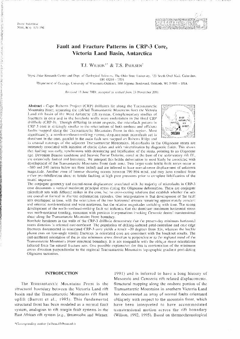
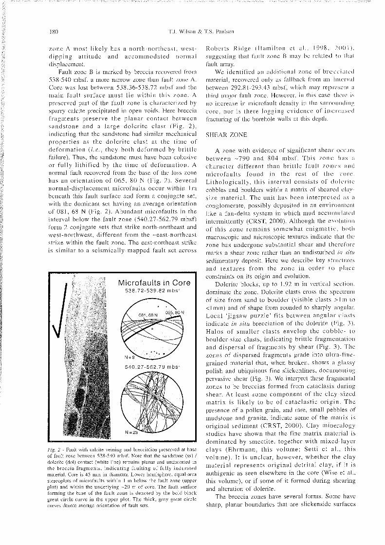
Fault zone B is marked by breccia recovered 1'roiii 538-540 mbsf, a more narrow zone than fault zone A. Core was lost between 538.36-538.72 mbsf i i i l ~ l the main fault surface must l ie within this zone. A preserved part of the fault zone is characterized by sparry calcite precipitated in open voids. Here breccia ' raginents preserve t h e planar contact between sandstone and a large doler i te clast (Fig . 2 ) , indicating that the sandstone had similar mechanical properties a s the doler i te clast at the t ime of deformat ion (i .e . , they both deformed by bri t t le failure). Thus, the sandstone must have been cohesive o r fully l i thif ied by the t ime of deformat ion. A normal fault recovered from the base of the loss zone lias an orientation of 065, 8 0 N (Fig. 2 ) . Several normal-displacement microfaults occur within 1 m beneath this fault surface and form a con.jugate set, with the dominant set having an average orientation of 081, 68 N (Fig. 2). Abundant microfaults in the interval below the fault zone (540.27-562.79 mbsf) form 2 conjugate sets that strike north-northeast and west-northwest, different from the -east-northeast strike within the fault zone. The east-northeast strike is similar to a seismically-mapped fault set across
I Microfaults in Core 538.72-539.82 mbsf
540.27-562.79 mbsf
Fig. 2 - Fault with calcite veining and brecciation preserved at base of fault zone between 538-540 mbsf. Note that the sandstone (ss) / dolerite (dol) contact (white line) remains planar and undistorted in the breccia fragments. indicat ing fault ing of fully indurated material. Core is 45 mm in diameter. Lower hemisphere, equal-area stereoplots of microfaults within 1 m below the fault zone (upper plot) and within the underlying -20 m of core. The fault surface forming the base of the fault zone is denoted by the bold black great circle curve in the upper plot. The thick. grey great circle curves denote average orientation of fault sets.
Roberts Ridge (Hamilton et al . , 1998, P O 0 l ) ,
suggesting that fault zone 13 may he related in ih:il f'ault array.
We identified an additional /.one of brcci.-iiiti.'d material, recovered only as fallback from an in~i.~rv:il between 292.81-293.43 mbsf. which may repri.-scn~ :I third major fault zone. However, i n this case lln-rc is n o increase in microfault density in the s~~r ronnd i i ip core , nor is there logging evidence of inercasi.-d fracturing of the borehole walls at this depth.
SHEAR ZONE
A zone with evidence of significant shear occurs between -790 and 804 mbsf. This z o n e 1i;is a character d i f ferent than bri t t le fault z o n e s a n d microfaul ts found in the rest of t h e co re . Li thological ly , this interval consis ts of dolcriii., cobbles and boulders within a matrix of sheared cl;iy- size material . The unit has been in terpre ted ;is ii
conglomerate, possibly deposited in an environmeni like a fan-delta system in which mud acc~ininlaici l intermittently (CRST. 2000). Although the evolution of th is zone remains somewhat en igmat i c , b o ~ h macroscopic and microscopic textures indicate that tlu- zone has undergone substantial shear and therefore marks a shear zone rather than an undisturbed if1 ,s i t / /
sedimentary deposit. Here we describe key structures and textures f rom the zone in order t o place constraints on its origin and evolution.
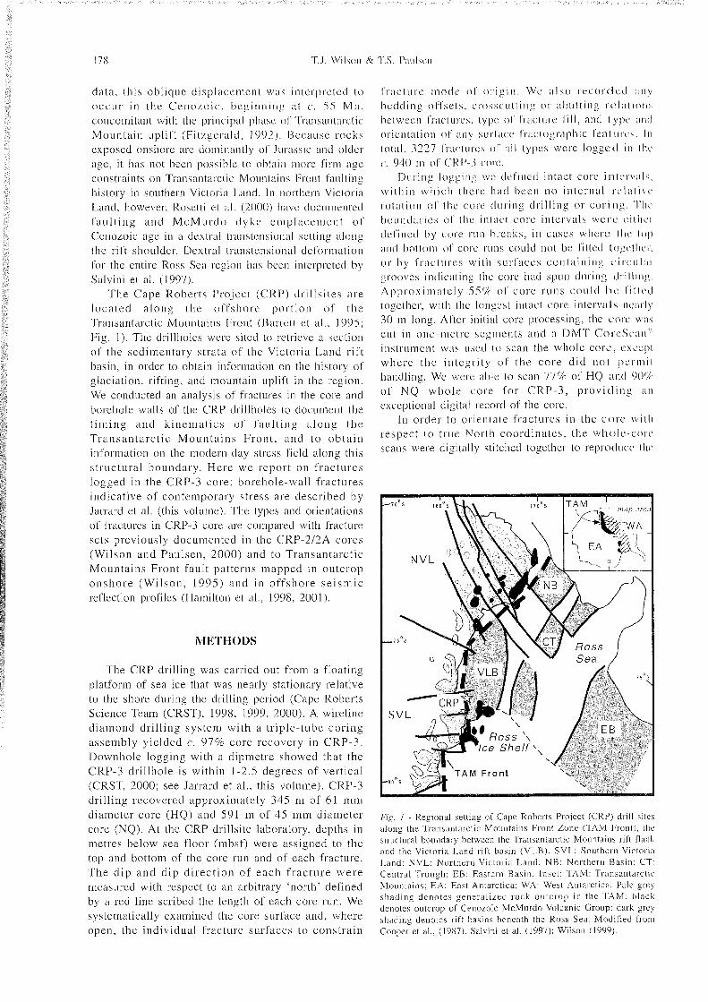
Dolerite blocks, up to 1.92 in in vertical section. dominate the zone. Dolerite clasts cross the s~~cc t r i i~ i i of size from sand to boulder (visible clasts > l 111 to <lmm) and of shape from rounded to sharply anp11:ir. Local "jigsaw puzzle' fits between angular clasts indicate in situ brecciation of the dolerite (Fig. 3 ) . Halos of smal ler c las ts envelop the cobb le - to boulder-size clasts, indicating brittle fragmentation and dispersal of fragments by shear (Fig. 3 ) . The zones of dispersed fragments grade into ultra-fine- grained material that, when broken, shows a glassy polish and ubiquitous fine slickenlines, doc~~iiienting pervasive shear (Fig. 3). We interpret these fragmental zones to be breccias formed from cataclasis during shear. A t least some component of the clay-sized matr ix i s l ike ly to b e of ca tac las t ic o r ig in . T h e presence of a pollen grain, and rare, small pebbles of mudstone and granite, indicate some of the matrix is original sediment (CRST, 2000). Clay mineralogy studies have shown that the fine matrix material is dominated by smectite, together with mixed-layer c l ays (Ehrmann , th is volume; Set t i e t a l . , th is volume). I t is unclear, however, whether the clay mater ia l represents or ig inal de t r i ta l clay, if it is authigenic as seen elsewhere in the core (Wise et al., this volume), or if some of it formed during shearing and alteration of dolerite.
The breccia zones have several forms. Some have sharp, planar boundaries that are slickenside surfaces

Fie. 3 - A . Brecciated zone within shear zone at 790-804 mbsf: unrolled \\hole-core scan is 141.4 m m across. B. Highly polished and slickenlined. black 'glassy' matrix inijicating intense shear of breccia matrix. Core is 45 mm in diameter.
with low to moderate dips. whereas others are steeply are sub-parallel to the average 'bedding' plane attitude dipping (Figs. 3 & 4). Irregular bodies, or zones with picked from BHTV and core scan analysis (Jarrarci et one planar and one irregular margin, also occur. The al., this volume) (Fig. 4). planar boundaries of the fragmental zones d o not There is a variety of evidence that the brecciatecl have any strong preferred orientation, although some material and the fine-grained matrix have flowed.
Fig. 4 - A. Steep. planar band of fine-grained breccia injected upward from moderately-dipping breccia zone: note upward injection (arrow) and thin veins of fine-grained breccia emanating from zone. Unrolled whole-core scan is 141.4 mm across. B. Lower-hemisphere. equal- area stereoplot of planar breccia margins in orientated core from the shear zone. Note parallelism of many of the margins to the 'average bedding plane' derived from analysis of BHTV and scanned core by Jarrard et al. (this volume).
Hiich of the geometric types of brcccia is associiitcil with 'veins' of l'riig11ient;il rjiiiteriiil th ; i t branch or ler~iiinate upward o r liitcrally. indicating in,jection into nd.jacent intact dolcrite clasis (Fig. 4 ) . The black matrix material f'orms wispy in,jections into cliist interiors, partially brcaking(them lip (I"ig. 3). Ductile flow of the matrix is also indicated by microscopic Slow folds i n the laniinatei-1 clay matrix of brecciated intervals (Millan et al.. 2000).
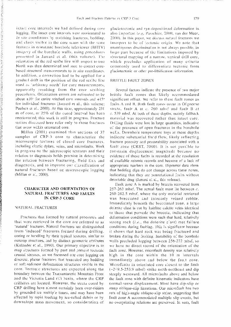
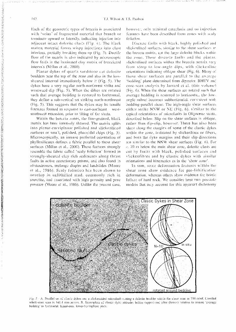
P lanar dykes of quartz sandstone cut doleri te boulders near the top of the zone and also in the less- sheared interval immediately below i t (Fig. 5). The dykes have a very regular north-iiortliwest strike and westward clip (Fig. 5) . When thc dikes are rotated such that average bedding is restored to horizontal. they define a sub-vertical set striking north-northwest (Iiig. 5). This suggests that the dykes niiiy be tensile fractures formed in response to cast-northeast - west- southwest extension, prior to tilting of the strata.
Within the breccia zones. the fine-grained, black matrix has been intensely sheared. The matrix splits into planar-curviplanar polished and sl ickenlined surfaces or small, polished. phacoidal chips (Fig. 3). Microscopically, an intense preferred orientation of phyllosilicates defines a fabric parallel to these shear surfaces (Millan et al.. 2000). These features strongly resemble the fabric called 'scaly foliation' formed in strongly-sheared clay-rich secliments along thrust 'auks in active accretionary prisms, and also found in olistostromes, melange diapirs and landslides (Moose e t a l . , 1986) . Scaly foliat ion has been shown to develop in unlitliified mud, commonly rich i n smectite, and associated with high porosity and pore pressure (Moose et al., 1986). Unlike the present case.
Iio\vvvci~. only minimal cataclasis and no itiii- '~Uoii I~cii~iiri-'S liiiyr been described from /.ones w i t l ) s r d y f'oliiition.
Discrete fanits with black. highly polished ; i i i ( l
slickenlinei.1 sui~l'iic~:s, similar to the shear surl'iires i n the hrecciii iiiiitrix. cut the kirge dolerite blocks williin the zone. These d iscre te faults and the ~ i I i i n ; i r ,
slickenliiiccl surfaces within the brcccia matrix viir!, f r o m steep to lo \~ / - i i~ lg le clips, with s l i c k r n l i m ~ orientatioiis indicating oblique shear (Fig. 6). Many of these shciir sin-races a rc parallel to the iivrsa!.;e 'bedding' plane determined fro111 dipmcter, BE-I'l'V iind core-scan analysis by Sarrarcl et al . (this vo lume) (Fig. 6). When the shear surfaces are rotated such thiil average bedding is restored to horizontal. Ilie low iingle subset becomes subhorizontal. consistent witlj bedding-parallel shear. The high-angle shear surfaces ei ther str ike NNW o r N E (Fig. 6 ) , s imi lar to tin- typical orientations of microfaults in Oligocene stral;i, described below. Slip o n the shear surfaces is obli(1iic, rather than dip-slip. however. There has a l so been shear along the margins of some of the clastic dykes within the zone. indicated by slickenlines o r I'ihri's. and both the dyke margins and their slip directions are similar to the NNW shear surfaces (Fig. (A). I:or c. 20 in below the main shear zone, dolerite clasts arc cut by faults with black. pol ished s ~ i r f a c ~ s and s l ickenf ibres a n d by c las t ic dykes with similar orientations and kinematics as in the 'shear zone'.
In sum. some deformation features within the shear zone show ev idence fo r pre-lithil ' ication deformation. whereas others show evidence for brittle failure of hard rock. We consider here two possible models that may account for this apparent dichotomy
Fie. 3 - A. Parallel set of clastic dykes and a slickensided mici-ofault cuttins a dolerite boulder within the shear zone at 790 mbsf. Unrolled L
whole-core scan is 141.4 mm across. B. Stereoplots of clastic dyke attitudes before (upper) and after (lower) rotation to restore 'average bedding' to horizontal. Equal-area. lower-hemisphere plots
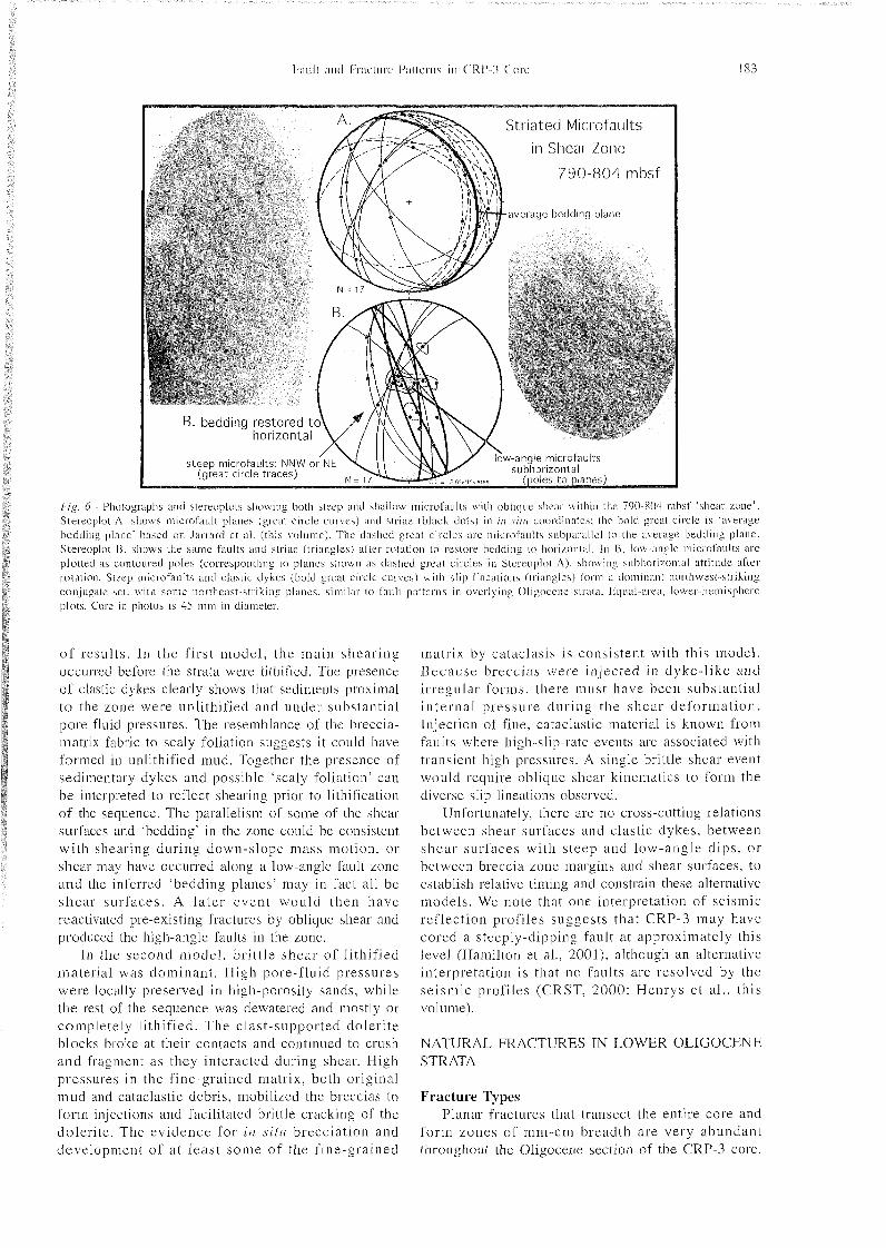
/.?g. 6 - Photographs and slereoplots showing both steep and shallow miuofaiilts with oblique slie:ii- \\ithiit the 790-804 mbsf 'shear /.one'. Stereoplot A . shows i~iicrofault planes (area! circle curves) and striae (black dots) in in ,sit11 coordinates: the bold great circle is 'average bedding plane' based on Jarrarcl et al . (this volume). The dashed great circles are microfaults subparallel to the average bedding plane. Slereoplot B. shows the same faults and striae (triangles) after rotation to restore bedding to ho r i~on ta l . In B. low-angle in i c ro fa~~ l t s arc plotted as contoured poles (corresponding to planes shou 11 as dashed great circles in Stereoplot A) . showing subhori~onlal attitude after rotation. Steep mic ro fa~~ l t s and elastic dykes (hold great circle curves) n i t h slip lineations (iriangles) form a dominant nortliwest-striking conjugiite set. with some 1101-tlieast-striking planes. similar to f'ault patterns in overlying Oligocene strata. Equal-area. lower-hemisphere plots. Core in photos is 45 mm in diameter.
o f results . In the f irst model , the main shear ing occurred before the strata were lithified. The presence of clastic dykes clearly shows that sediments proximal t o the zone were unlithified and under substantial pore fluid pressures. The resemblance of the breccia- matrix fabric to scaly foliation suggests it could have formed in unlithified mud. Together the presence of sedimentary dykes and possible 'scaly foliation" can be interpreted to reflect shearing prior to lithification of the sequence. The parallelisn~ of some of the shear surfaces and 'bedding' in the zone could be consistent with shearing during down-slope mass motion, or shear may have occurred along a low-angle fault zone and the inferred 'bedding planes' may in fact all be shea r surfaces . A la ter event would then have reactivated pre-existing fractures by oblique shear and produced the high-angle faults in the zone.
In the second model . bri t t le shear of lithified material was dominant . High pore-fluid pressures were locally preserved in high-porosity sands, while the rest of the sequence was dewatered and mostly or completely l i thif ied. The clast-supported doleri te blocks broke at their contacts ancl continued to crush and fragment as they interacted during shear. High pressures in the fine-grained matrix, both original mud and cataclastic debris, mobilized the breccias to form injections and facilitated brittle cracking of the doleri te. The evidence for i n s i t i i brecciation and development of a t leas t some of the f ine-grained
matrix by cataclasis is consistent with this model. Because breccias were in.jected in dyke- l ike and irregular forms, there must have been substantial in ternal pressure dur ing the shear deformat ion. Injection of fine, cataclastic material is known from faults where high-slip-rate events are associated with transient high pressures. A single brittle shear event would require oblique shear kinematics to form the diverse slip lineations observed.
Unfortunately. there are n o cross-cutting relations between shear surfaces and clastic dykes, between shea r surfaces with steep and low-angle d ips , o r between breccia zone margins and shear surfaces, to establish relative timing and constrain these alternative models. We note that one interpretation of seismic refle,ction profiles suggests that CRP-3 may have cored a steeply-dipping fault at approximately this level (Hamilton et al., 2001), although an alternative interpretation is that no faults are resolved by the se ismic profiles (CRST. 2000; Henrys e t a l . , this volume).
NATURAL FRACTURES IN LOWER OLIGOCENE STRATA
Fracture Types Planar fractures that transect the entire core and
fo rm zones of mm-cni breadth are very abundant throughout the Oligocene section of the CRP-3 core.
I lere we discuss those that we could clussil'y as iatural fractures based o n textures, f i l l niiitcrial. o r association with definite natural frac~ui~es. We exclude a population of planar fractures of 'iiutctcrminate' origin that could e i ther be natural o r ititlitcetl in origin. During core logging. the n;ituriil fractures were categorized as microfaults. veins. o r clastic ciykcs. I t is important to note, however, dial these categories overlap for two reasons. First. the great ma.jority of demonstrable faults are also mincrali~ed. domin;intly by calcite. Second, textures visible on the whole-core surface were comn~only insufficient to unambiguously dist inguish carbonate-cemented faults from fine- grained clastic dykes in cases where bedding was not present to identify offset (Millan et al.. 2000; Millan. 200 1 ).
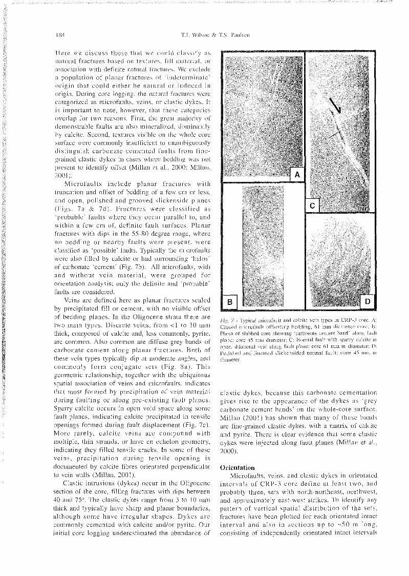
Microfaul ts inc lude planar fractures with truncation and offset of bedding of a few cm or less. and open. polished and grooved slickensidc planes l - ' i g s . 7 a & 7 d ) . Fractures were classif ied a s 'probable' faults where they occur parallel to. and within a few c m of. definite fault surfaces. Planar fractures with dips in the 55-80 degree range. where n o bedding o r nearby faul ts were present , were classified as 'possible' faults. Typically the rnicrofa~~lts were also filled by calcite or had surrounding 'halos" of carbonate 'cement" (Fig. 7b). All ~nicrofa~ilts. with and wi thout vein mater ia l , were grouped fo r orientation analysis; only the definite and "probable" faults are considered.
Veins are defined here as planar fractures sealed by precipitated fill or cement, with no visible offset of bedding planes. In the Oligocene strata there are two main types. Discrete veins, from < l to 10 mm thick, composed of calcite and, less comn~only, pyrite, are common. Also common are diffuse grey bands of carbonate cement along planar fractures. Both of these vein types typically dip at moderate angles. and c o n ~ m o n l y f o r m conjugate se ts (F ig . 821). T h i s geometric relationship, together with the ubiquitous spatial association of veins and n~ ic ro fa~~ l t s , indicates that most formed by precipitation of vein material during fault ing or along pre-existing fault planes. Sparry calcite occurs in open void space along some fault planes, indicating calcite precipitated in tensile openings formed during fault displacement (Fig. 7c). More rarely, ca l c i t e veins a re compound wi th multiple. thin strands, or have en echelon geometry, indicating they filled tensile cracks. In some of these veins, prec ipi ta t ion dur ing tens i le opening is documented by calcite fibres orientated perpendicular to vein walls (Millan. 2001).
Clastic intrusions (dykes) occur in the Oligocene section of the core, filling fractures with dips between 40 and 75". The clastic dykes range from 3 to 10 mm thick and typically have sharp and planar boundaries. al though s o m e have i r regular shapes . Dykes a r e commonly cemented with calcite andlor pyrite. Our initial core logging underestimated the abundance of
Fig. 7 - Typical microfault and calcite vein types in CRP-3 core. A ; Closed microfault offsetting bedding. 61 mm d iame te r core: B: Photo of slabbed core shoving 'carbonate cement band' along I':I~II{ plane: core 45 mm diameter: C: Normal fault with sparry calcite in open. clilalional void along fault plane: core 61 mm in cliameter: I ) : Polished and lineated slickensided normal fault: co re 45 nun i n diameter
clastic dykes, because this carbonate cementation gives rise to the appearance of the dykes as 'grey carbonate cement bands' on the whole-core surface. Millan (2001) has shown that many of these bands are fine-grained clastic dykes. with a matrix of calcite and pyrite. There is clear evidence that some clastic dykes were injected along fault planes (Millan et al.. 2000).
Orientation Microfaults, veins. and clastic dykes in orientated
in tervals of CRP-3 core def ine at leas t two , and probably three. sets with north-northeast, northwest, and approximately east-west strikes. To identify any pattern of vertical spatial distribution of the sets, fractures have been plotted for each orientated intact in terval and a lso in sec t ions up to -50 m long. consisting of independently orientated intact intervals
that I ' o r i i i nearly complete composite sections. I n m;~iiy intervals, two or three different co~i.jugate sets strikiii;: NNE. NW. or WNVV to ENE tire present. I n other in~ervals. one of' the sets is well developed. with on ly rare members of the oilier se ts . Basecl on avail:il)Ic data , it does not appear that any set is spatially restricted to discrete intervals of Oligwene s t ra ta . Ri.~presenttitivc populations from selected orient;ited intervals are described here.
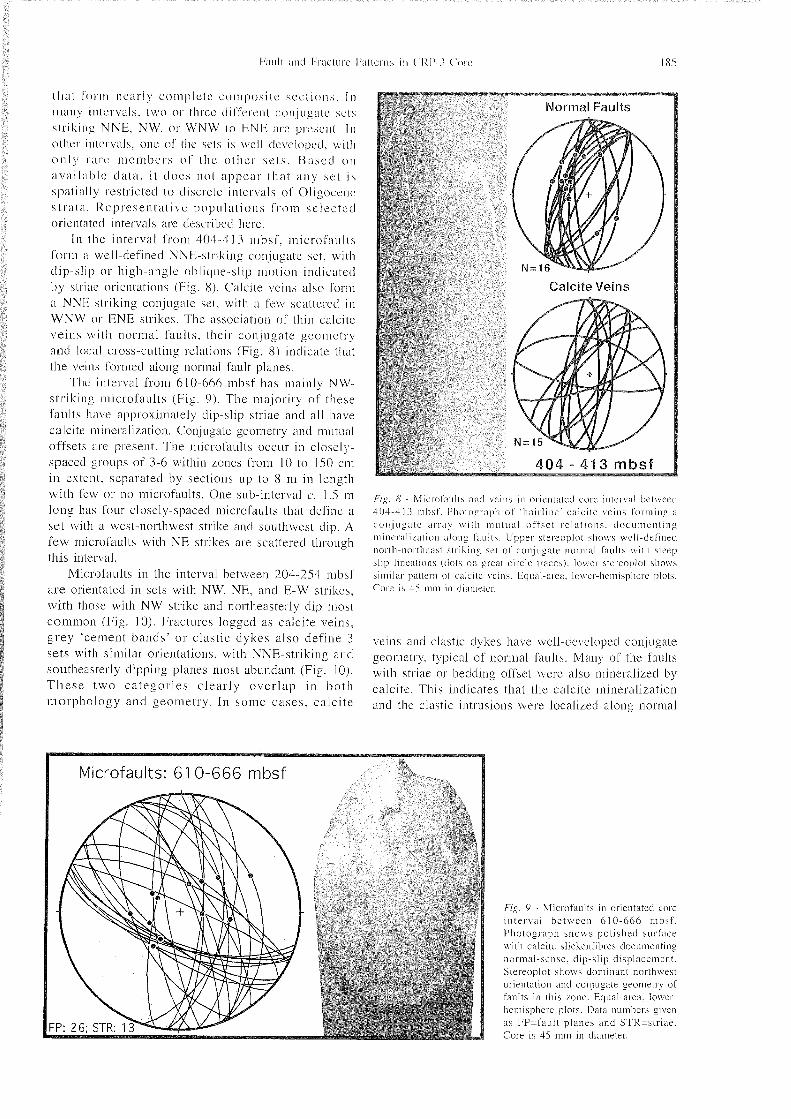
I n the interval from 404-413 mbsf. microfaults form a well-defined NNE-striking con.jugate set. with dip-slip or high-angle oblique-slip motion indicated by ~triiie orientations (He. 8). Calcite veins also fonn a NNK-striking con,jugatc set, with a lew scattered i n WNW o r RNE strikes. The association of thin calcite veins with normal faults, their conjugate geometry and loci11 cross-cutting relations (Fig, 8) indicate that the veins Ibrmed along normal fault planes.
The interval from 610--666 mbsf has mainly NW- striking mic ro fa~~ l t s (Fig. 9) . The majority of these faults have approximately dip-slip striae and all have calcite mineralization. Conjugate geometry and mutual offsets are present. The microfaults occur in closely- spaced groups of 3-6 within zones from 10 to 150 c111 in extent. separated by sections up to 8 m in length with few or no microfa~ilts. One sub-interval c. 1.5 m long has four closely-spaced microfaults that define a set with a west-northwest strike and southwest dip. A few inicrofa~~lts with NE strikes are scattered through this interval.
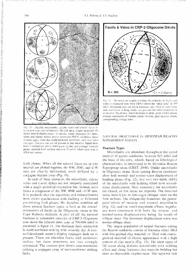
Microfaults in the interval between 204-254 mbsf are orientated in sets with NW. NE. and E-W strikes. with those with NW strike and northeasterly dip most common (Fig. 10). Fractures logged as calcite veins, grey 'cement bands' or clastic dykes also define 3 sets with similar orientations. with NNE-striking and southeasterly dipping planes most abundant (Fig. 10). T h e s e two categor ies clearly over lap in both morphology and geometry. In some cases. calci te
f ig . <S' - Mierol'aiilts and veins in oricntatcd core interval between 404-413 iiibsf. Pliotogrupli o f 'hairline' calcilc beins formini; a c o n j i ~ g a t c arl-a) with i i i ~ ~ t u a l on'scl relat ions. docuiiicnting mineralisation along faults. Upper stereoplot s1iov.s well-defined iiortli-nortlicasi striking set of con.jui;ate noniial faults v, it11 steep slip lineations (dots o n great circle trace\): lo\\cr stcrcoplot sliows similar pattern o f calcite vei~is. Equal-area. lower-hemisphere plots. Core is 4.1 m m in (liiimetci-.
veins and clastic dykes have well-developed conjugate geometry. typical of normal faults. Many of the faults with striae or bedding offset were also mineralized by calcite. This indicates that the calcite mineralizatio~i and the clastic intrusions were localized along normal
Fig. 9 - Miei-ofaults in orientated core interval between 610-666 mbsf . Pliotogi~iipli shows polished surface v\ it11 calcite slickenfihres documenting normal-sense. clip-slip displacement. Stereoplot shou s do~iiin~int northwest orientation and con,j~~i;ate georiietry of faults in this zone. Equal-area. lower- hemisphere plots. Data numbers given as FP=fault planes and STR=sti-iae. Core is 45 mm in diameter.
Faults & Veins in CRP-3 Oligocene Strata 1
/Â¥';g 1 1 - Summary stereoplot sho\vine the attitudes of I'aulls :III(I ~ ' i i i s in oricnti~tcd core from CRP-3 ahove the 'shear [one' ;I! 700 i h s l ' . Ilornii~iiiit sets arc north-northeast and close to ca s l \\\-\I: note northwest-slrikins faults arc present but more s c a l k ' m l in oriciitation. Equal-area. lower-Iiemispherc plots: great c i r ck~s ilenoli" averaae orienlation of fracture planes in core, grey squares ilciiok' con'cspoilclill~ avcrage poles.
P';,?. 10 - Parallel microl'aults. calcite veins and clastic dykes i n orientated core interval between 204-254 mbsf. Upper stereoplot (F) shows 1101-mal-clisplaceii~enl microfa~~lts: center stereoplot ( V ) shows veins a n d clastic dykes: l o ~ c r slei-coplot (F&V) combines these fracture types. Note that north-northeast. northwest, and -east-west conjugate fracture sets are all present in this interval. Equal-area. owcr-licmisplici-e plots: bold great circles a r e average f racture planes selected from contour maxima. Unrolled \X hole-core scan is 19 l .6 mm across.
fault planes. When all the natural fractures in this interval are plotted together, the NW, NNE, and E-W sets are clearly delineated, each defined by a con.jugate fracture array (Fig. 10).
In each of these examples, the microfaults, calcite veins and clastic dykes are not uniquely associated with a single preferred orientation but, instead, each forms a component of the NW. NNE and -E-W sets. It is probable that the injections and mineralization were either synchronous with faulting or followed pre-existing fault planes. We therefore combine all these natural fracture types to look at the overall orientation of faults in the Oligocene strata at the Cape Roberts dri l lsi te. A plot of al l the natura l fractures in orientated intervals of CRP-3 Oligocene core above the inferred shear zone at 790-804 mbsf is presented in figure 11. The dominant fault orientation is north-northeast-striking with westerly dip. A less- well-developed, easterly-dipping conjugate fault set is present. There are abundant faults with northwest str ikes, but these structures a re less s t rongly orientated. The contour plot shows concentrations defining a conjugate array of west-northwest striking faults.
NATURAL FRACTURES IN DEVONIAN BI<ACON S UPERGROUP STRATA
Fracture Types Microfaults are abundant throughout the cored
interval of quartz sandstone between 823 inbsf and the base of the core. which, based on lithological characteristics. is interpreted to be Devonian Beacon Supergroup strata (CRST, 2000). Unlike micsofa~~lts in Oligocene strata, those cutting Beacon sandstone show both normal- and reverse-sense displacement o f bedding planes (Fig. 12). Just over two thirds (68%) of the microfaults with bedding offset have normal- sense displacement. Most commonly the microfaults are closed, so few striae are exposed. The observed striae have high- to low-angle oblique rakes on the fault surfaces. The oblique-slip lineations, the general parallel ism of reverse and normal n~ ic ro fau l t s (Fig. 12), and the small-magnitude offsets, together are most consistent wi th both the reverse- and normal-sense displacements being the resul t of oblique shear. The dominant displacement sense was normal-oblique shear.
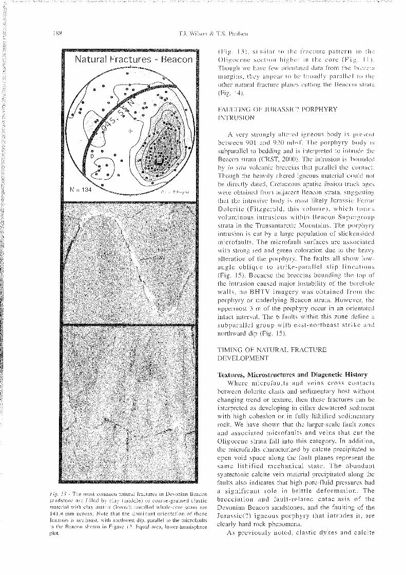
The largest population of natural fractures cutting the Beacon sandstone consist of fractures either filled with fine-grained clay material, or filled with coarse- grained material of clastic appearance with a high content of clay matrix (Fig. 13). The same types of fill occur along definite microfaults with bedding offset and along fractures that truncate bedding but show no discernible displacement. This apparent lack

of displacement is due to the lack of visible bedding marker pkmes, or may be ascribed to the large width o f the fill re la t ive to the typically small offset magnitudes. During initial core logging we considered that the fracture fill could be of either cataclastic or clastic (i.e. sedimentary injection) origin. However. our preliminary microstr~~ctural analysis shows that these zones a re characterized by finer grain size, greater range of grain size, and more angular grains than the adjacent host rock, which we interpret as indicating cataclastic grain-size reduction (Millan et al., 2000). The abundant clay matrix within them may b e partly ca tac las t ic in origin. but most likely a significant proportion is derived from alteration of the detri tal f e ldspa r component in the sandstone by hydrothermal activity that affected this part of the co re (CRST. 2000) . Clasts in the fracture fill are clearly derived from the host quartz arenites. Given the Devonian age of the strata. they must have been fu l ly l i thif ied when these f rac tures formed and. therefore, sedimentary injections are unlikely. The fact that the majority of the filled fractures have a strong preferred or ienta t ion para l le l to the def in i te microfaults with bedding offset is consistent with their formation as faults (Fig. 13).
Brecciation has affected approximately 36% of the Beacon strata in the core (CRST, 2000) . Beacon fragments with angular to subrounded shapes float in a matrix of coarse sand-sized material derived from the host rock (Fig. 14). Rotation of planar bedding between clasts within the breccia documents post- lithification fragmentation. Rotation of beddin* 0 on a larger sca le wi th in the Beacon is present and is appears to be associated with this brecciation (Jarrard et al.. this volume). Whole-core observations indicate that most of the breccias are planar bodies with sharp margins and steep dips that truncate bedding (Fig. 14). This suggests the breccias may mark fault zones. In addition, however, the breccias locally branch into steep dyke-like bodies crossing bedding (Fig. 14) or sill-like bodies parallel to bedding, suggesting that some of the breccias were injected.
? . 1 lie breccias in the Beacon s t ra ta may have formed by fa~il t ing. Where Ilevonian Beacon rocks crop out in the Tra~isantarctic Mountains, however. discrete faults are present but are not associated with extensive brecciation (Korsch, 1984; Pyne, 1984; Morrison, 1989: Wilson, 1993). Therefore, if t h e breccias in the core arc fault-related. their extensive development is most likely due to the structural posit ion of the cored Beacon strata a long t h e Transantarctic Mountains Front. Alternatively, the breccias could have formed under high fluid pressure conditions at the time of intrusion of the inferred Jurassic Ferrar Dolerite body. Ferrar Dolerite intrudes t h e Devonian Beacon strata extensively in the Transantarctic Mountains. Hydrotherinal alteration associated with the doleri te emplacement is well documented there (Craw and Findley, 1984) , but development of breccias in mountain outcrops has on ly been observed where the Jurass ic doler i te intrudes the uppermost, Permo-Triassic portion of the Beacon Supergroup (Grapes et al . , 1974; Korsch, 1984; Elliot, 1998), not in Devonian Beacon strata. Based on the steep, planar form of the breccia bodies, their occurrence in strata that are cut by abundant fractures and faults, and the absence of intrusion- related breccias in Devonian Beacon strata in the Transantarctic Mountains, we tentatively favor the interpretation that the breccias in the core are fault- related.
Orientation The microfaults and filled fractures interpreted as
cataclastic faults have a strong preferred orientation. with a northeast str ike and a moderate d ip to the northwest (Figs. 12 & 13). Compared to the faults and fractures cutting Oligocene strata. this orientation is similar. but the strike is more easterly and the dip angle is shallower. Unlike the natural fractures in the Oligocene strata. conjugate geometry is nearly absent in the fractures cutting the Beacon strata. In addition to the prominent northeast fault set, there are weak concentra t ions of nor thwest -s t r ik ing f rac tures
Natural Fractures - Beacon
Fig. 13 - The most common natural fractures in Devonian Beacon sandstone are filled by clay (middle) or coarse-srainecl clastic material with clay matrix (lower): unrolled whole-core scans are 141.4 mm across . Note that the dominant orientation of these fractures is northeast. with northwest dip. parallel to the iiiicrofaults in the Beacon shown in Figure 12. Equal-area. lower-hemisphere
FAULTING; 01: JURASSIC" PORPHYRY INTRUSION
A very strongly altered i ~ i c o i i s body i s pi'esrni between 901 a n d 920 mbsf. The porphyry body is
s~~bparallel to bedding and is interpreted to intrude fin.' Beacon strata (CRST. 2000). The intrusion is bountled by i à xi/n volcanic breccias that parallel the colitact. Though the heavily altered igneo~is material could no^
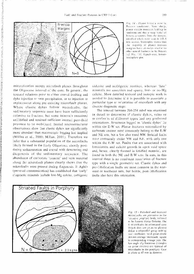
be directly dated. Cretaceous apatite fission-tr:tcli agc,s were obtained from ad,ji~'cnl Beacon strata. sii;;i,'csliiijl that the intrusive body is most likely Jurassic I~erixr Doler i te ( F i t q e r a l c l . this volume), w h i c h forms voluminous intrusions within Beacon Supci.gi.onp strata i n the Transaiitarctic Mountains. The porphyry intrusion is cut by a large population of slickensided microfaults. The microfault surfaces are associated with strong red and green coloration due to the heavy alteration of the porphyry. The faults all show low angle obl ique to str ike-parallel s l ip l ineat ions (Fig. 15). Because the breccias bounding the lop of the intrusion caused major instability of the borehole walls . no BHTV imagery was obta ined f r o m tlu' porphyry or underlying Beacon strata. However, (lie uppermost 3 111 of the porphyry occur in an oricntiiled intact interval. The 6 faults within this zone define ii
subpara l le l group with eas t -nor theas t s t r ike a n d northward dip (Fig. 15).
TIMING OF NATURAL FRACTURE DEVELOPMENT
Textures, Microstructures and Diagenetic History Where microfaul ts and veins c ross contacts
between dolerite clasts and sedimentary host without changing trend or texture. then these fractures can be interpreted as developing in either dewatered sediment with high cohesion or in fully lithified sedimentary rock. We have shown that the larger-scale fault zones and associated microfa~i l t s and veins that cut the Oligocene strata fall into this category. In addition, the n~ ic ro fa~~ l t s characterized by calcite precipitated in open void space along the fault planes represent the same l i thif ied mechanical s ta te . T h e abundant syntectonic calcite vein material precipitated along the faults also indicates that high pore-fluid pressures had a s igni f icant ro le in br i t t le de fo rmat ion . The breccia t ion and faul t - re la ted ca tac la s i s of the Devonian Beacon sandstones, and the faulting of the Jiirassic(?) igneous porphyry that in t rudes i t , are clearly hard-rock phenomena.
As previously noted. clast ic dykes and calcite
/Â¥ ' i 1-1 - I'l:iniir hrecciii /one i n Beiicon ~ i i n d s ~ o n e . Noie sharp. pl;tn;ir n~;it-pin truticatcs bedding in sandstone :md that it steep 'dyke' of lirccci;~ etii;in;ites I'rnni the margin: unrolled whole-core scan is 141.4 mill itcross. .Slcrcoplol slioivs lhal Ilie ma,jority of planiii" breccici mat-sins have attilinlcs s i ~ n i l a r t o oilier niitm'iil lractures in tlic Beacon (c/'. Fig. 13) . I<~~ital-;ireii. lower- hemisphere plot.
miner;iliztition occupy microfault planes throughout the Oliaocene interval of the core. I n general, the textural relations point to either coeval faulting and dyke in.jection or vein precipitation, or to injection or replacement along pre-existing niicrofault planes. Where c l a s t i c dykes follow m i c r o f a ~ ~ l t s , the sedimentary sequence must have been sufficiently cohesive to fracture, but some intervals remained unlithified and retained sufficient internal pore-fluid pressure to be mobilized. Init ial microstructural observations show that clastic dykes are significantly more abundant than macroscopic logging had implied (Millan e t al., 2000; Millan. 2001 ). Therefore we infer that a substantial population of the microfaults likely formed in the Early Oligocene, shortly post- dating sedimentation and coeval with dewatering and d iagenes i s of the sedimentary sequence . T h e abundance of carbonate 'cement' and vein material a long the microfault planes clearly shows that the microfa~~l ts were present during diagenesis. F. Agliib (personal communication) has established that 'early' diagenetic minerals include low-Mg calcite, authigenic
s ider i te a n d autl i igenic zeoli tes. whereas ' la te ' minerals are smectites and sparry, low- or no-Mg calcite. More detailed textural and isotopic work is needed to determine if it is possible to associate a particular type or orientation of microfault with any discrete diagenetic stage.
The interval between 204-254 mbsf was examined in detail to de te rmine if c las t ic dykes , veins o r microfaults of different types had any preferred orientations. Structures logged as 'clastic dykes' lie within the E-W set. Planar fractures mineralized by carbonate cement most commonly belong to the E-W and NE sets. but a few also trend NW. Striated faults most commonly strike NW and NE, with only one within the E-W set. Faults that are associated with brecciation and calcite growth in open void space and, hence, clearly formed in lithified material, are found in both the NE and E-W sets. In sum, in this interval there is no consistent association of fracture type with a single geometric set. Clastic dykes and pre-lithification faults are most common in the east- west or northeast sets. but brittle, post-lithification faults also have this orientation.
Striated Faults in Porohvrv
Fig. 15 - Polished and lineated microfa~il ts are pervasive in the intrusive porphyry body. inferred to be Jurassic Ferrar Dolerite. The 6 microfaults in orientated core (black dots are poles to planes) define a subparallel group striking east-northeast: bold great circle denotes average microfault. square is corresponding average pole. The low-angle slip lineations (triangles on great c ircles) a re typical of microfaults in the porphyry. Core in photo is 45 mm in diameter.

Relation to Hydrotliermal Activity Microfaults. fracture-fill material. and breccias in
the Devonian Beacon strata have undergone extensive liydrothermal alteration. The ubiquitous microfaults wi th in the porphyry intrusion have also been j2ervasively altered. An obvious candidate to drive the hydrothermal activity is the igneous intrusion itself. K e c a ~ i s e the intrusion is interpreted to be Ferrar Dolerite of Jurassic age (Fitzgerald, this volume: 'ompelio et al.. this volume), this would require dial tlie liydrother~iial activity occurred in the Jurassic at the t ime of intrusion. This would imply that the microfa~dts c i l l t i ~ i ~ b o t h the intrusion and the Beacon stixta must be Jurassic. or possibly older in the case of the Beacon structures. The fact that most of the known and inferred microfaults in the Beacon strata arc approximately parallel to the dominant microfaults set in the overlying Oligocene strata, would appear to contradic t this interpretation, because it s eems unlikely that a Jurassic fault set and an Oligocene 'aul t set would be so well al igned. It seems more likely that all the northeast faults would have formed i n the same overall sifting event, in Oligocene or younger t imes . If this is t h e case , then young hydrothermal activity must have occurred. At this point i t i s not c lear how hydrothermal activity associa ted with brecciation and faul t ing of the Devonian and Jurassic 'basement ' of the basin fill might be linked with the mineralization above in the Ol igocene section. Future i so topic work on vein material may shed light on this important issue.
Cross-cutting Relations Microfaults. and veins interpreted as mineralized
microfa~~lts . commonly show conjugate geometry and mutual cross-cutting relations, indicating synchronous development. Conjugate relations were not uniquely associated with any one of the fracture sets defined based on orientation in the Oligocene strata. Fractures in the Beacon strata do not show conjugate geometry or cross-cutting relations.
Due to the sampling bias imposed by the vertical core, few cross-cutting relations between the fractures were observed. For example, in the interval between 204-254 mbsf, only four cross-cutting relationships were observed. In three of four, NW-striking faults cut and displaced either NE or E-W structures. In the other case, a NE fault cut and displaced an array of E-W striking bands that are probably clastic dykes. If representa t ive , these re la t ions sugges t the E - W fractures are the oldest and the N W faults are the youngest of the three geometr ic se ts . However, a simple age sequence such as this is not supported by the textural evidence discussed above.
Fault Attitude vs. Bedding Dip: Tilt Test Jarrard et al. (this volume) have shown that the
main episode of east-northeast stratal tilting began in
M ioccne. b;iscd o n the observation t1i; t t hecklinp (lips def'ine a fanning array from iippermost CR1' 4 roi'r through upper CRP-2A core. We can use this ;is ;I
reference frame for evaluating the relative timiiig 0 1 ' faul t i~~g and stratal tilting. We have used t h e ii\'i,i'ajir orientalion of bedding from J;ii.r;n'd et ; \ l . ( t l i i s
volume) to apply a rotation to restore average)-- Ix~ildiny to hori~ontal, revolving bedding and fractures around tlie ;i\lerage line of beclding strike. Figure 10 shows the results for all orientated natural fractiin's i n Oligocene strata from CRP3 core above tlic 's1u~;ii~ zone' at 790-804 mbsf and i n Devonian Beacon sti'at;i between 823-90 1 mbsf.
The faults and fractures i n Oligoccne stnila I'orni well-defined con.jugate sets with 60-70 dcgro." dips i n their i n s i t u unrotatecl or ienta t ions . T h e r lv ; i~ . conjugate geometry of the dominant NNE- stri k i n " fault set is distorted upon rotation to restore lied(lin;! to horizontal. suggesting that these faults formcil af'trr tilting of the strata (Fig. 16). This would imply ;I
Late Oligocene or younger age for the microfaiilts. Northeast-striking, northwest-dipping microt'anlts
and fractures are predominant in Beacon strata. This fault set has an average attitude of 046. 55N befoi.1- rotation. and is restored to an attitude of 03 1 , 6iSW when bedding is rotated to horizontal (Fig. 16). T in restored attitude is more typical of normal fault dips, consistent with the displacement sense on the ma,jority of the microfaults. This suggests that the domiiiiint
Unrotated Rotated
the la te Early Ol igocene and ended by the Ear ly tilting
Fig. 16 - Slereoplots show average attitude of planes in Oligoccne strata above 790 mbsf (upper) and in Beacon between 823-901 mbsf (lower). with in situ coordinates (left) and after rotation to restore average bedding to horizontal (right). Note the clearly defined conjugate fault pattern in the Oligocene strata becomes distorted by the rotation. suggesting the faulting post-dated stratal tilting. In contrast. the strongly dominant northeast-striking fracture set in the Beacon at tains a ' typical ' normal fault dip that is subparallel to the in situ Oligocene normal fault attitude after rotation. suggesting these faults may have formed prior to stratal
N E - s t r i k i ~ faults may have i'ormed prior to tilting of the se(1in:nce. implying an Kiirly Oligocenc or older age. Relation of the steep microl'aiilts ancl the elastic dykes i n the 'shear mnc' . 700-804 nihsf. illso points to their formation prior to stixtal tilting (Figs. 5 & 6). The prolilt orientation of the Beacon fracture set is nearly identical in dip to the faults in the Oligocene strata. (hough the strike remains -15 degrees more easterly. This suggests that faulting of about the same orientation continued i n later liarly Oligocene a n d Late Oligocene times. Possibly the oblique shear on the Sriiclures below the shear Lone (790-804 mbsf) and i n the Beacon occurred i n this period, because they had been rotated out of optimum orientation for continued dip-slip motion by the strata1 tilting.
INDUCED FRACTURES IN CRP-3 CORE
PETAL. PETAL-CENTRELINE AND CORE-EDGE FRACTURES
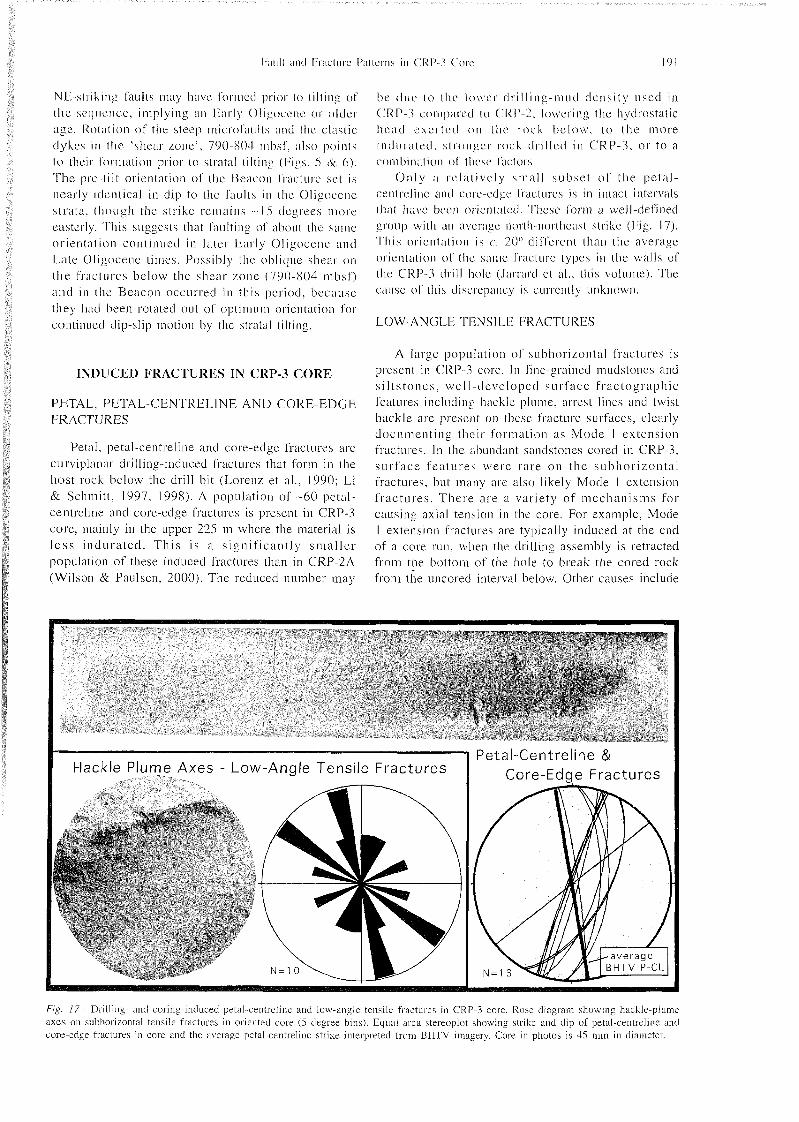
Petal, petal-centreline and core-edge fractures are c~irviplanar drilling-induced fractures that form in the host rock below the drill bit (Lorenz et al.. 1990; Li & Schmitt. 1997. 1998). A population of -60 petal- centreline and core-edge fract~ires is present in CRP-3 core, mainly in the upper 225 111 where the material is l e s s indura ted . Th i s i s a significantly sma l l e r population of these induced fractures than in CRP-2A (Wilson & Paulseii, 2000). The reduced number may
i c tine to tin- lower dri Iling-mud density iiscd in ( 'RP-3 compairtl ~o ('RP-2. lowering the hydrostatic lic;i<l exrr lcd on tlic rock below. to the more iiidunitcd. stronger rock drilled i n CRP-3. or to a comhi n;itioii ol' tlit'sc f;ictors.
Only ;I s eh i~ ive ly small subset of the petal- centreline and core-edge f'ractures is i n intact intervals thii~ have been oricniiitcd. Thcst; form a well-defined group with an avcragc northnorthcast strike (Fig. 17). r. I his orientation is c. 20" different than the average orientation of the same fracture types in the walls of the ('RP-.l drill hole (Iarrard et al.. this volume). The cause of this discrepancy is currently unknown.
LOW-ANGLK THNS11,K FRACTURES
A large population of subhorizontal fractures is present i n CRP-3 core. I n fine-grained inudstones and s i l t s toncs . well-developed surface f rac tographic features inclncling hackle plume. arrest lines and twist hackle are present o n these fracture surfaces, clearly documenting their formation as Mode l extension fractures. I n the abundant sandstones cored in CRP-3, surface fea tures were rare on the s~ibl ior izonta l fractures, but many are also likely Mode 1 extension f rac tures . There are a variety of mechanisms for causing axial tension in the core. For example, Mode l extension fractures are typically induced at the end of a core run, when the drilling assembly is retracted from the bottom of the liole to break the cored rock from the ~ ~ n c o r e d interval below. Other causes include
Hackle Plume Axes - Low-Angle Tensile Fractures Petal-Centreline &
Core-Edge Fractures
Fig. 17 - Drilling- and col-ing-induced petal-centreline and low-angle tensile fractures in CRP-3 core. Rose diagram showing hackle-plume axes on s~~bhorizontal tensile fractures in oriented core ( 5 degree bins). Equal area stereoplot shoiving strike and dip of petal-centreline and core-edge fractures in core and the axerage petal-centreline strike interpreted from BHTV imagery. Core in photos is 45 mm in diameter.

l02 . . I ..l. Wilson it' T.S. I ' t n i i s r i i
r;iising the hydraulic chuck during drilling, handling- related flexure of the core, and disking where tension arises when the core is released From the host rock upon entering the core barrel.
A small population of low-angle tensile fractures with hackle plume structures is present i n orientated core . The hackle plume axes show a well-defined NNW trend (Fig. 17). Kulander and others (1990) have shown that. in the Appalachian Basin of eastern North America, propagation directions of these types of induced fractures. as mapped by the hackle plume trends, are controlled by the direction of maximum horizontal in situ stress in the host rock around the drill hole. The parallelism between tlic average trend of p lume axes in CRP-3 co re and the max imum hor izonta l s t ress direction defined by borehole breakouts in the drillhole walls demonstrates the same stress control of low-angle tensile fracture propagation at CRP-3.
SIGNIFICANCE OF CRP-3 FRACTURE PATTERNS
TIMING OF BRITTLE DEFORMATION
Microfaults in Ol igocene strata of CRP-3 a re intimately associated with injection of clastic dykes and with mineralization by diagenetic fluids. This shows that fault ing was early. synchronous with dewatering and lithification of the strata, pointing to a n Early Oligocene age. Our 2 i l t tes t ' , however, suggests that microfaults in CRP-3 Oligocene strata above 790 mbsf formed after the major period of strata1 tilting, which would imply a latest Oligocene
Tab. l - Summary description of CRP-3 core fractures
Category
Brittle Fault Zones A: -260 mbsf
B: -539 mbsf
Shear Zone
Natural Fractures - Oligocene Strata
Natural Fractures - Devonian Beacon
Strata
Jurassic? Porphyry
Drilling-Induced Fractures
Fracture Types -
Breccia: veins
Breccia: veins
A. Breccia Margins
B. Clastic Dykes
C. Striated Microfaults
A. Microfaults
B. Veins (mainly calcite)
C. Clastic Dykes
A. Microfaults
B. Filled Fractures
(cataclastic faults?)
C. Breccia Margins
Microfaults
A. Petal-Centreline
B. Low-angle Tensile
o r younyci iige. Ik~iiring i n mind. however, (lie v r r \ supiil sci.iiiiicniiition vales iinci short time in~ i .~ ivn l spanned by tlic ('RI-'-3 strati\, these timing in(li~-;i~oic, are not inco~isisic~it . I~aultingtmay have p051 dii~ril deposit ion o l most CRP-3 strata ( b c ~ \ v r n l approxinititcly 35-3 1 Ma), but commencetl i n llic latest Htirly Oligocene or Late Oligocene prior 1 0
complete lithifieation of the s e q u e n c e . O u r c1ociiment;ition of hrittlc faulting of very c'ohi.~sivr sedinient or Sully lithif'ieci rock indicates I ' ; ~ ~ i I t i i i ~ :
continued siibsc~~uent to deposition, lithif'ication. innl tilting. hut we have n o firm upper limit on l':uill iigr (Tab. 1 ).
, . 1 he timing ol' faiilting i n the Devonian Bctii.'oii Supergroiip strtita ancl the Jurassic( '?) igneous porphyry that intriides i t is more difficult to consti.iiii~ definitively. One possibility is that the extensive faulting. brccciation and hydrothermal alteration of these units occurred in the Jurassic, approxiniiiti.%ly coeval with intrusion of the porphyry. Two I'ac~ors argue against this . First. no s imi lar extens ive deformation is associated with Jurassic Ferrar Dolerite intrusions into Devonian Beacon strata in the ; ~ l , ] ; ~ ~ ~ e i i t Transantarc t ic Mountains. Second. it wou ld h e fortuitous for faults formed in a Jurassic even! to lie nearly identical in orientation as Oligocene ril't--rclti~~-d faulting. as observed. Although we can not rule this possibility out with available data, we suggest (hat i t is more likely that the deformation w e observe is re la ted to development of the Transant;ireli(: Mountains Front zone. This fault zone must have accommodated c. 3000 m of down-to-the-east ol'fset of the Beacon and Ferrar rocks and must have initiated by the latest Eocene - earliest Oligocene.
Geometry
NNE. W dip [probable]
ENE. N dip [pmbablej
A. NW.hTE. scattered
B. NNW. subvertical
C. NW. NE & s~ibparallel to
'average bedding': oblique
slip
All types: NNE. NW. ENE
conjugate sets: mainly normal-
sense dip-slip shear
A. NE, W dip: oblique slip
B. NE. W dip
C. NW. NE. scattered
ENE. N dip: oblique slip
A. NNE-NNW strike
B. Plume axes: NNW
Interpreted Age -
<Eariy Oligocene
<Early Oligocene
A. Early Oligocene
B. Early Oligocene
C. ?Early Oligocene. Late
Oligocene or younger
AH types: late Early
Oligocene - Late Oligocene
or younger
All types:
Early Oligocene?
[Jurassic??]
Early Oligocene?
[Jurassic??]
Both: Contemporary Stress
Field
Fai~ll imil 1-r:H-lure J?itterns in CR1'-'l Core 193
which is the age of the oldest sedimentary rocks rest in^ o n the unconformity with the Devonian Beacon 'basement' at Cape Roberts (CRST, 2000). Our ' t i l l test ' suggests that the faults cutting the Beacon I'osmed prior to the main episode of strata1 tilting, which occurred in late Early Oligoccne-Late Oligoccne times (Jarrard et al., this volume). This is consistent with an 'early' faulting episode of latest Eocene - Early Oligocene age affecting the Beacon strata. We suggest that this early episode records the ma.jor down-to-the-east displacement a long the Trassan~ t i r c t i c Mountains front that dropped the Beacon floor of the rift basin. The NNE-striking, W- clipping dominant fault set in CRP-3 core and mapped a t Roberts Ridge is younger, according to our 'tilt test', and most likely formed as the hinge margin of the basin flexed in response to Late Oligocene and younger subsidence due to growth faulting on the eastern margin of the Victoria Land Basin. A key test to discriminate between the alternatives of Oligocene or Jurassic faulting of the Beacon strata is to establish whether or not there is any relationship between the extensive hydrothermal activity that affected the breccias and northeast-striking fractures in the Beacon s t ra ta and the migrat ion of large volumes of diagenetic fluids along the northeast-striking fractures in the Oligocene strata above.
KINEMATIC HISTORY FROM NATURAL FRACTURE SETS
The conjugate geometry and normal-sense, mainly dip-slip displacement associated with the microfaults in the Oligocene strata down to the 'shear zone' at 7 9 0 mbsf, documents a vertical maximum principal s t r e s s during deformat ion. Below that depth , moderate- to low-angle s l ip l ineations become common, indicating ob l ique shear ing, al though normal-sense displacement remains dominant. Because t h e oblique lineations occur on fault surfaces with b o t h shallow and s teep dips , i t i s l ikely that the oblique shear marks reactivation of existing fracture surfaces. Some rare cases of multiple striae on fault surfaces support this interpretation. This interpretation implies that oblique shear followed the dominant normal-sense dip-slip fault displacement.
The fracture record from the intervals of CRP-3 that are orientated does not indicate any change in natural fracture strike with respect to age of strata or depth in the core and, therefore, we can not assign an age to the north-northeast or northwest fracture sets w e have documented (Table 1). This same geometric pattern persists stratigraphically upward through the CRP-2A strata of la te Ear ly Ol igocene and Late Oligocene age (Wilson and Paulsen. 2000). Based on these results, it appears that the same strain regime persisted through the Oligocene. Because we have no f i rm constraint on the relative timing of conjugate f a u l t arravs with di f ferent str ikes. we can not
determine whether these represent d iscre te ilcl'ormation episodes or i f their I'orination overlapped i n t ime. The association of clastic dykes and inincnilization with all of them suggests, however, that they can not be significantly different in age. I f only the dominant north-northeast and west-northwest geometr ic sets are considered, one poss ible interpretation is that development of the fault sets overlapped in time, with the orientation of the two horizontal stresses remaining approximately constant, but the relative magnitudes switching (cf. Angelier e t al . , 1984). The strong clevelopment of the north- northeast striking fault array indicates that a north- northeast-trending maximum horizontal stress was the dominant regime. We note that this fault set i s oblique to the overall north-northwest orientation of the Transantarctic Mountains Front zone, implying oblique, transtensional shear along this structural boundary. A very similar geometric pattern of Cenozoic faults was documented by Rosetti et al . (2000) along the Victoria Land coast c, 100 km north of Cape Roberts, indicating the regional significance of this structural array and associated transtensional deformation.
ORIENTATIONS OF NATURAL FRACTURE SETS WITH RESPECT TO REGIONAL STRUCTURE
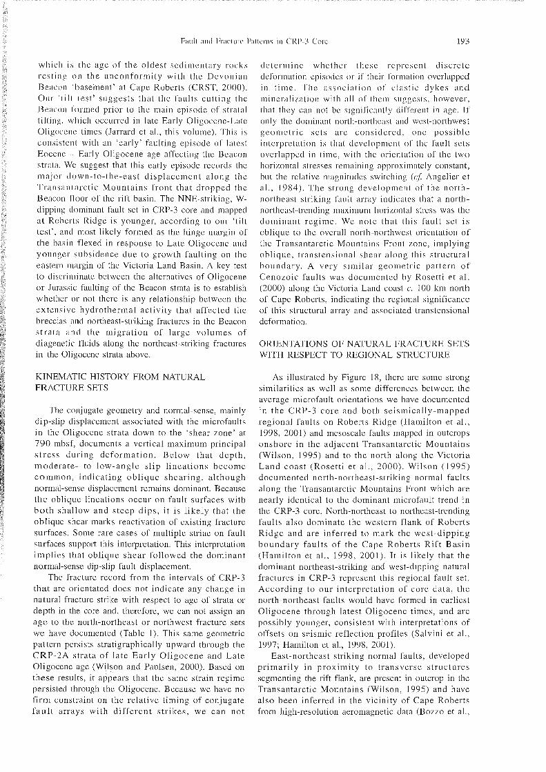
As illustrated by Figure 18, there are some strong similarities as well as some differences between the average microfault orientations we have documented in the CRP-3 core and both seismically-mapped regional faults on Roberts Ridge (Hamilton et al., 1998, 2001) and mesoscale faults mapped in outcrops onshore in the adjacent Transantarctic Mountains (Wilson, 1995) and to the north along the Victoria Land coast (Rosett i e t a l . , 2000). Wilson (1995) documented north-northeast-striking normal faults along the Transantarctic Mountains Front which are nearly identical to the dominant microfault trend in the CRP-3 core. North-northeast to northeast-trending faults also dominate the western flank of Roberts R idge and are inferred to mark the west-dipping boundary faul ts of the Cape Roberts Rif t Basin (Hamilton et al., 1998, 2001). It is likely that the dominant northeast-striking and west-dipping natural fractures in CRP-3 represent this regional fault set. According to our interpretation of core data, the north-northeast faults would have formed in earliest Oligocene through latest Oligocene times, and are possibly younger, consistent with interpretations of offsets on seismic reflection profiles (Salvini et al., 1997; Hamilton et al., 1998, 2001).
East-northeast striking normal faults, developed pr imari ly i n proximity to transverse s t ructures segmenting the rift flank, are present in outcrop in the Transantarctic Mountains (Wilson, 1995) and have also been inferred in the vicinity of Cape Roberts from high-resolution aeromagnetic data (Bozzo et al.,
/Â¥'is; 18 - Orientation of natural fractures and in sit^^ contemporary minimum horizontal stress directions with respect to offshore l'anlls nl I l lc Cape Roberts Rift Basin (CRRB) and Roberts Riclge from Hamilton et al. ( 1 998) and onshore rnesoscalc faults in Transantarctic Mountains outcrops from Wilson (1995): black lines are NNE faults: dark grey lines are NVV faults: pale grey lines are ENE faults. Notr tliat the dominant north-northeast natural fracture set in the core (stereoplot) is parallel to the dominant onshore fault set and t o tlu- fanlt r a y bordering the CRRB. The average transverse fault trend derived from core data is oblique to the east-northeast fault se t s mapped onshore and across Roberts Ridge. The contemporary stress direction (black double arrow) is nearly perpendicular to the regional trend ol [lie frontal fault zone of the Transantarctic Mountains. mapped by Hamilton et al. (2001) as the McMurdo Sound Fault Zone (MSI-'/.l. whereas the natural fracture sets are oblique to this zone. The large grey arrow shows the average strata! dip from core. borehole awl seismic data
1997) and mapped across the Roberts Ridge area by Hamilton et al. (1998, in press). Within individual intact intervals of CRP-3. m i c r o f a ~ ~ l t s have east- northeast to east-west orientation but, on average throughout the core, have a west-northwest strike different from the onshore and Roberts Ridge fault patterns. The brittle fault zone at 539 n~bs f , inferred to mark larger displacement, probably has an east- northeast orientation.
No faults parallel to the north-northwest trend of the Transantarctic Mountains were found onshore (Wilson, 1995). Hamil ton e t al. (1998, 2001) interpreted the main Transantarctic Mountains Front Zone offshore, termed by them the "McMurdo Sound Fault Zone", to have a northwest trend. They mapped northwest-trending faults along the western border of the Cape Roberts Rift Basin. Further north along the Transantarctic Mountains Front, Rosetti et al. (2000) found northwest-trending extensional and dextral strike-slip faults. Overall there is no well-developed, strongly orientated northwest-striking fault set in CRP-3 core, however northwest-striking faults are relatively common.
Though differing in some respects, in total the microfault pattern in CRP-3 core is strikingly similar to the orientations of previously mapped onshore and offshore faults in the region. Most significantly, a north-northeast fault se t dominates the pat tern , consistent with interpretations invoking Cenozoic dextral transtensional shear along the Transantarctic Mountains Front boundary (Wilson, 1992; 1995; Salvini et al., 1997; Rosetti et al., 2000). Our age data from CRP core indicates that this it likely to be of Early Ol igocene and younger age. We note , however, that dextral transtension of Oligocene age is not consistent with the inferred north-northwest
orientation of offshore growth faults implied by the east-northeast dips of fanning stratal sequences.
CONTEMPORARY STRESS DIRECTIONS
Borehole breakouts in the walls of the CRP-3 drillhole demonstrate that the present-day minimum horizontal stress direction is orientated east-northcasi (Jarrard et al., this volume). This orientation is fully compatible with the large population of dr i l l ing- induced petal-centreline and core-edge f ractures documented in CRP-2A core (Wilson and Pci~~lscn, 20001, but is at a small oblique angle to the much smaller population of these induced fractures in CRP- 3 core. The east-northeast minimum stress direction from CRP core and borehole data is oblique to the topographic slope of Roberts Ridge, and therefore we interpret it to record the in si tu crustal stress direction in the Cape Roberts region. Based on considerations of frictional constraints and the types of i n c l ~ ~ c e d fractures that occur within the CRP core and borehole walls, a strike-slip to normal-faulting crustal stress regime, in the sense of Anderson (1951,), has been modeled (Moos e t al . . 2000; Jarrard et a l . , this volume). Modeling studies by Li and Schmitt (1998) indicate that the presence of both disc and petal- centreline fractures is compatible with either a normal faulting or strike-slip faulting stress regime, so our CRP core data is consistent with this interpretation.
T h e eas t -nor theas t orientation of the in s i tu min imum st ress d i rect ion is approximately perpendicular to the regional trend of the Transantai-ctic Mountains Front structural boundary (Fig. 18). It is not con~patible with the oblique stress orientations inferred from the natural fracture sets. One possible explanation for this is reorientation of

A C K N O W L E D G M E N T S - This work w;is I'iinilcd by NSE grant O P P - 9 5 2 7 3 9 4 to Wilson. The drilliiig te;ini ;iiid Alcx I'ync deserve great credit l'or !he successful cor ing o p e r a t i o n s . O u r c o r e f r a c t u r e loggii lg d e p e n d e d o n t h e careful w o r k of the C R P - 3 corc processors. J o Anderson . Cliff Alkins. Nick Jackson iind Milt! Piitcrson. Slicllcy Judge carried mit core scanning at the Drill Site Laboratory. liric Plankell d i d the digital 'core stitclii~ig'. and Shelley Judge compiled t h e core fracture da ta and liclped with rotat ions and plotling of the fracture data: this pro,jcct could not have b e e n comple ted without their high-quality work. C r i s t i n ; ~ Millan made an inventory of CRP-3 iiiicrostriictiiral features f o r her 1 3 . S ~ . thesis. We thank Christian Bnecker and Rich Jarrard For obtaining the oricntii[cd downhole logs used in o u r analysis. Rich Jarrard also completed much of the core o r i e n t a t i o n w o r k that f o r m s the bas i s of t h e or ien ta t ion analysis w e present here. DMT, Germany, provided reduced r a t e s f o r l e a s e of t h e CoreScanGO f o r t h e C a p e R o b e r t s Project and Nodi Rafat donated his time to help with setup of the ins t rument at t h e Dri l l S i t e Labora tory . W e thank R i c k A l l m e ~ i d i ~ i g e r for providing stereonet programs used for our da ta analysis. Fabrizio Storti provided many useful comments that helped to improve this paper.
REFERENCES
Anclerson E M . . 195 1 . The D\ncunics of Faulting. Oliver & Boyd. Edinburgh. 206 p.
Angelicr J . . Colletta B. & Anderson R .E . . 1984. Ncogene palacostress changes in the Basin and Range: A case study at Hoover Dam. Nevada-Arizona. Geological Society of America Bu~lletin. 96. 347-361.
Barrett P.J.. Henrys S.. Bartek L.R.. Brancolini G.. Busetti M,. Davey F.J.. Hannah M.J. & Pyie A.R.. 1995. Geology of the margin of the Victoria Land basin off Cape Roberts. southwest Ross Sea. In: Cooper A.K.. Barker P.F. & Brancolini G. (eds.). Geology and Seismic S t r a t i g i ~ ~ p l ~ y of the Antarctic Margiii, Antarctic Research Series. 68. AGU. Washington. 183-208.
Bozzo E.. Ferraccioli F. & Wilsoii T.. 1998. Structural Framework of a High Resolution Aeromagnetic Survey. Southwestern Ross Sea (Antarctica). Terra Antartica. 4. 51-56.
Cape Roberts Science Team. 1998. Initial Report on CRP-1, Cape Roberts Project, Antarctica. Terra Antarctica. 5. 1-187.
Cape Roberts Science Team. 1999. Studies from the Cape Roberts Project. Ross Sea. Antarctica. Initial Report on CRP212A. Terra Antarctica. 6. 1- 173.
C a p e Roberts Science Team. 2000. Initial Report on CRP-3. Supplement, Cape Roberts Project. Antarctica. Terra Antarctica. 7 . 1-305.
Cooper A.K.. Davey F.J. & Behrendt J .C . . 1987. Seismic stratigraphy and structure of the Victoria Land Basin. western Ross Sea. Antarctica. In: Cooper A.K. & F.J. Davey (Editors). The Antarctic Continental Margin; Geology and Geophysics of f11e Western Ross Sea (Circuni-Pacific Council Energy and Mineral Resources Earth Sci. Ser.. 5B) Houston. TX. USA. 27- 65.
Craw D. & Findlay R.H., 1984. Hydrothermal alteration of Lower Ordovician granitoids and Devonian Beacon Sandstone at Taylor Glacier. McMurdo Sound. Antarctica. Ne\v Zealand Journal of Geoloe}' & Geo/.~/iysics. 27. 465-475.
Ehrmann W.U.. 2001. Variations in smecti te content and crystallinity in sediments from CRP-3. Victoria Land Basin. Antarctica. This volume.
lilliol l ) . l l . . IOOS. l-'ni;i! ~ i l ~ i \ ' a t o i i i ; i j ; i i i ; ~ ~ i s ~ i ~ : precursor to flooil
Strcss patterns observed by boreholc telcviewer logging of the CRP-3 drillhole. Victoria 1,and Basin. Antarctica. This volume.
Korscli R.J., 1984. The sti-ucturc of Shapeless Mountain. Antarctica, and its relation to Siirassic igneous activity. /\ieir 7<~(1 l ( ind Journal o f Gco/o,y\' due/ G( '~/J/IJ .S~C,\ . 27. 487-504.
Kulander B.R.. Dean S.L. & Ward B.J. Jr.. 1990. Fmrliired Core A11n1j.si.s: I i ~ t ~ i ~ / ~ r e ~ a ~ i o n . Lo fe ing . and U,\e of N a t ~ ~ r n l crnd Induced Fractures in Core. American Association of Petroleum Geologists Methods in Exploration Series. No. 8. 88 p.
Li Y. & Sclimitt D.R.. 1997. Wcll-bore bottom stress concentration and incliiceci core fractures. American Association of Petroleum Geologist.\ Bu~illetin. 81. 1909- 1925.
Li Y. & Schmitt D.R.. 1998. Drilling-induced core fractures and in situ stress. Journal o f Geophysical Research. 103. 5225-5239.
L o r e n ~ J.C.. Finlcy S.J. & Warpinski N.R.. 1990. Significance of cosing-induced fractures in Mcsavcrdc core. northwestern Colorado. American Associat ion o,f Petroleum Geologis ts Bulletin. 74. 1017-1029.
Millan C. 2001. Analysis of Microstructures in Core from the Victoria Land Basin. Antarctica. The Ohio State University. Colurnbus. BSc. Thesis.
MiHan C.. Wilson T. & Paulsen T.. 2000. Microstructural analysis of faults and veins in corc from the Victoria Land rift basin. Antarctica. GSA Abstracts with Progranl. Annual Meeting.
Moore J.C.. Roeske S.. Lundberg N.. Schoonn~aker J.. Cowan D.S.. Gonzales E. & Lucas S.E., 1986. Scaly fabrics from Deep Sea Drilling Project cores from forearcs. In : Moore. J.C.. ed., Structural Fabrics in Deep Sea Drilling Project Core.5 From Foream. Geological Society of America. Memoir 166. 55-74.
Moos D., Jarrard R.D.. Paulsen T.. Scholz E. & Wilson T.. 2000. Acoustic Borehole Televiewer (BHTV) Results from CRP- 212A. Victoria Land Basin. Antarctica. Terra Amartica. 7 . 279- 286.
Morrison. A.D.. 1989. Geological observations from Terra Cotta Mountain. upper Taylor Glacier. ?II' Zealand Antarctic Record. 9. 3 1-43.
Passchier S.. 2000. Soft-sediment deformation features in Core from CRP-212A. Victoria Land Basin. Antarct ica. Terra Antarticc~. 7. 401-412.
Paulsen T.. Wilson T.. Moos D.. Jarrard R. & Wilson G.. 2000. Orientation of CRP2A core. Term Antarficu. 7 . 271-278.
Pompilio M , . Armienti P. & Tamponi M , , 2001. Petrography. mineral composition and geochemistry of volcanic clasts and the niagmatic body of CRP-3. Victoria Land Basin. Antarctica. This volume.

'yne. A.R.. 1984. Geology of the Mt. l-'leming area, South Victori;~ Land. Antarct ica. Ncir '/.(,tilnml . loi ir i~i l o f (icolo,yy ( in(/ Geophysics. 27. 505-5 12,
Rosctti F.. Storti F. & Salvini I" . , 2000. Cciio/oic noncoiixiiil transtension along the western shoulder of the Ross Sea . Antarctica. and the emplaccmcni ol' McMi~rdo dyke arrays. Terra Nova. 12. 60-66.
S;ilvini F., Brancolini G. . Busetti M . . Storti I ' M a ~ z a r i n i l:. & Coren F., 1997. Ccnozoic geodynaiiiics of the Ross Sea region. Antarctica: Crustal extension, intraplate strike-slip faulting. and tectonic inheritance. J. Gc'o/~li\:\. Re's.. 102. 24.669-24,696.
Setti M,. Marinoni L. & Lopcz-Galindo A.. 2001. Crystal-cliciiiistry of the smectites in the sctiimcnis o f the CRP-3 dri l lcore. Victoria Land Basin, Ant;irctica:prcliminary results. Th i s volume.
I 'cssensohn F. & W6riicr G.. 1991. The Ross Sea rift system. Antarctica: structure. evolution a n d analogues. I n : Thomson M.R.A. . Crame J .A. & Thomson, J.W. (eds.), Goologiccil Evolution of Antarctica. Cambridge University Press, New York, 273-277.
Van tier Meer J.J.M.. 2000. Microscopic Observations on the Upper 300 of CRP-212A. Victoria Land Basin. Antarctica. Terra Antartica, 7. 339-348.
Wilson T.J.. 1992. Mesozoic and Ccnozoic kinematic evolution of
the Tni~~.s:~nt:i~-ctic Moinitains. In: Yoshicla Y., Kumimnn:~ K . ,V Sliiritishi K . (ct1s.j. Recent fio,yi~~.s.s iii Antarctic Earfh Scionr~,. 'I'cmi Sci.. Tokyo, Ml-,314.
Wilson. 'I'.S,. 100.3, Sur;issic faul t ing and iiia$iiiati.sin in lln-
(liditors), Lithosphere Dynamics am1 Environmental ('1i:ingr ol thc Ccnozoic West Antarct ic Rift Sys tem. G l o b a l (in11 l'l~iiifliiy Cti(i~i,ye. 23. 105- 127.
Wilson T.S. & Panlsen T., 2000. Brittle Deformation I'iittrriis of CRP-212A. Victoria Land Basin, Antarctica. Tern Aiit(irtini. 7. 287-298.
Wise W.. Smellic S.I.,. Aghib F.S., Jarrard R. & Krissek [..A., 2001. Authigeiiic smectite clay coats in CRP-3 (Irillcorr. Victoria Land Basin, Antarctica. as a possible indicatoi of lliiiil flow: a progress report. This volume,