FATIGUE USAGE LIFE AND GRADIENT FACTORS ASME …
43
© 2015 Electric Power Research Institute, Inc. All rights reserved. Steve Gosselin, PE Director LPI, Inc. Nuclear Regulatory Commission Public Meeting June 30, 2016 FATIGUE USAGE LIFE AND GRADIENT FACTORS for ASME CLASS 1 PIPING ANALYSES
Transcript of FATIGUE USAGE LIFE AND GRADIENT FACTORS ASME …

© 2015 Electric Power Research Institute, Inc. All rights reserved.
Steve Gosselin, PEDirector LPI, Inc.
Nuclear Regulatory CommissionPublic Meeting
June 30, 2016
FATIGUE USAGE LIFE AND GRADIENT
FACTORS for
ASME CLASS 1 PIPING ANALYSES

2© 2015 Electric Power Research Institute, Inc. All rights reserved.
Summary
Introduction Fatigue Mechanism and Testing Life and Gradient Factors Stage I and Stage II Life Example Application 2016 Activities

3© 2015 Electric Power Research Institute, Inc. All rights reserved.
INTRODUCTION

4© 2015 Electric Power Research Institute, Inc. All rights reserved.
Introduction
ASME Section III Code procedures introduced design practices that, when coupled with inservice inspections, provide confidence that reactor coolant pressure boundary components provide reliable service– Excellent performance of our operating plants is a testimonial to
these procedures Challenges not anticipated in the late 1960’s
– Reactor water effects– Plant life extension to 60 and 80 years– Flexible Operations

5© 2015 Electric Power Research Institute, Inc. All rights reserved.
Introduction
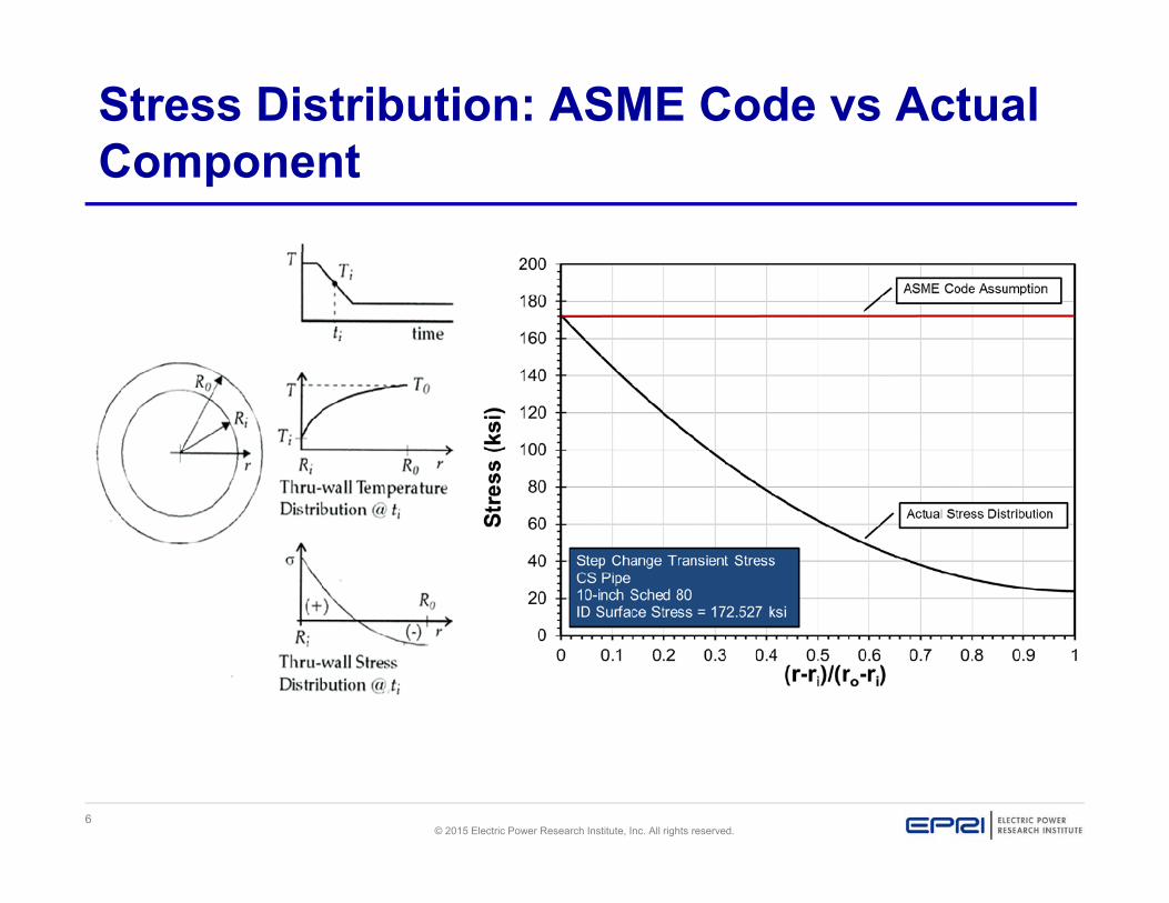
This work examined two aspects of ASME Code NB-3600 fatigue life (Usage) calculation procedures– Allowable fatigue life is based on fatigue testing small
diameter smooth test specimens and is subsequently applied to all Class 1 piping regardless of their actual thickness
– All component cyclic stresses are treated as uniform through-thickness membrane stresses and do not consider the presence of actual through-thickness stress gradients.
6© 2015 Electric Power Research Institute, Inc. All rights reserved.
Stress Distribution: ASME Code vs Actual Component

7© 2015 Electric Power Research Institute, Inc. All rights reserved.
Test Specimen Load Drop Crack Size
R
Test Specimen
a
CrackArea

8© 2015 Electric Power Research Institute, Inc. All rights reserved.
FATIGUE MECHANISM

9© 2015 Electric Power Research Institute, Inc. All rights reserved.
Fatigue Mechanism
Fatigue is predominantly the process of propagating a crack.
Fatigue process:Stage I – Initiation of microcracks– Microcrack growth and coalescence to form mechanically small
(short) cracksStage II– Propagation of mechanically small cracks (MSC)
characterized by EPFM – Component failure/load drop

10© 2015 Electric Power Research Institute, Inc. All rights reserved.
Fatigue Mechanism (ii)
Once a microcrack forms, it continues to grow along its primary slip plane as Mode II shear crack oriented 45 degrees to the stress axis.
At low strains, Stage I Mode II crack growth may extend across several grains
Increasing stress intensity promotes slip on systems and slip is no longer confined to planes at 45° to the stress axis
Crack begins to propagate as a Mode I (tensile) crack normal to the stress axis in Stage II growth. Cracking is governed by power laws of crack depth and plastic strain

11© 2015 Electric Power Research Institute, Inc. All rights reserved.
Fatigue Mechanism (iii)
Stage I Crack Growth – initially grow by shear (Mode II)
loading along preferential slip planes
– coalesce and propagate at decreasing rates to an engineering crack size
Stage II Crack Growth– characterized by an accelerating
crack growth rates – growth predicted by continuum
fracture mechanics methods. Crack shape: “half-penny”
Dowling (1977)

12© 2015 Electric Power Research Institute, Inc. All rights reserved.
Fatigue Mechanism (iv)
Stage I to Stage II transition crack depth is between150 m (0.006 in.) to 250 m (0.010 in.) Chopra and Shack (2001)
Depending on the nature of the loading, Stage I to Stage II transition can occur between 20% and 50% of specimen life

13© 2015 Electric Power Research Institute, Inc. All rights reserved.
FATIGUE LIFE TESTING

14© 2015 Electric Power Research Institute, Inc. All rights reserved.
Fatigue Strain-Life Testing (ii)
Chopra 1999

15© 2015 Electric Power Research Institute, Inc. All rights reserved.
ASTM Standard E 606-04
ASTM Standard E 606-04 – Smooth push-pull specimens tested under fully reversed
through-thickness uniform (membrane) loading conditions
– Strain/displacement controlled loading– Determination of failure may vary with the use: Separation: total separation or fracture of the specimenModulus Method: ratio of unloading-to-loading modulus is 0.5Force (Load) Drop: decrease in maximum force; typically 25% or
50%– Recent data reported in NUREG/CR-6909 Rev 1 defines Nfailure
at 25% load drop

16© 2015 Electric Power Research Institute, Inc. All rights reserved.
Fatigue Strain-Life Data
ASME Section III – Fig. I-9.1, I-9.2, or I-9.3 (tabularized in Table I-9.0) in the ASME
Section III Mandatory Appendices– Adjusted for maximum mean stress– Reduction factor of 2 on stress or factor of 20 on cycles– Life factor accounts for: 1) data scatter, 2) surface finish, and 3)
weak-link statistical size effects NUREG/CR-6909 Rev. 1
– S-N design curves based on best estimate fatigue statistical models
– Life was reduced by a factor of 2 on stress or 12 on cycles– Adjustments for size effects were limited to weak-link statistical
size effects

17© 2015 Electric Power Research Institute, Inc. All rights reserved.
NUREG/CR-6909 Rev. 1
Significantly larger database than original PVRC data– Argonne National Laboratory and Japanese data Mixture of 25% and 50% load drop data Air test temperatures between 25°C and 290°C Test specimens gauge diameters 0.2 inch to 0.375 inch All data normalized to 25% load drop criteria 25% load drop criteria is generally associated and with an
average 3-mm (0.118-in.) deep crack (Chopra and Shack 2001)
18© 2015 Electric Power Research Institute, Inc. All rights reserved.
STRESS GRADIENT AND SIZE EFFECTS

19© 2015 Electric Power Research Institute, Inc. All rights reserved.
Peak Stress
o o ip ab a a b b
P D MS K C K C K C E | T T |t Z
K E | T | E | T
1 1 2 2 3 3
3 1 2
21 1
2 1 1
o o1 1 m
P DK C2t
Membrane Term:
( )
i2 2 m b
MK CZ
Global Bending Term:
( )
3 3 ab a a b b b
3 1 b
2 g
K C E | T T |1 K E | T |
2 11 E | T
1
Thermal Gradient Terms:( )
( )
( )

20© 2015 Electric Power Research Institute, Inc. All rights reserved.
Through-wall Stress Distribution
20 m b g 1 b g 2 g
2 2m b g b g g
where: A A (2 3 ) / t A 1.5 / t
and:
(z) ( ) (2 3 ) / t) z 1.5 / t z
20 1 2(z) A A z A z

21© 2015 Electric Power Research Institute, Inc. All rights reserved.
Through-wall Stress Distribution (ii)
The nonlinear gradient stresses result from transient temperature changes at the inside surface of the pipe.
The through-thickness thermal stress (g) of an insulated cylinder with wall thickness t, subjected to a ramp/step temperature change at the inside surface (z = 0), can be expressed by [NUREG/CR-6674]:
2
g Gz z(z) 1 3 1.5t t
In the case G is the maximum radial gradient thermal stress at the inside surface
22© 2015 Electric Power Research Institute, Inc. All rights reserved.
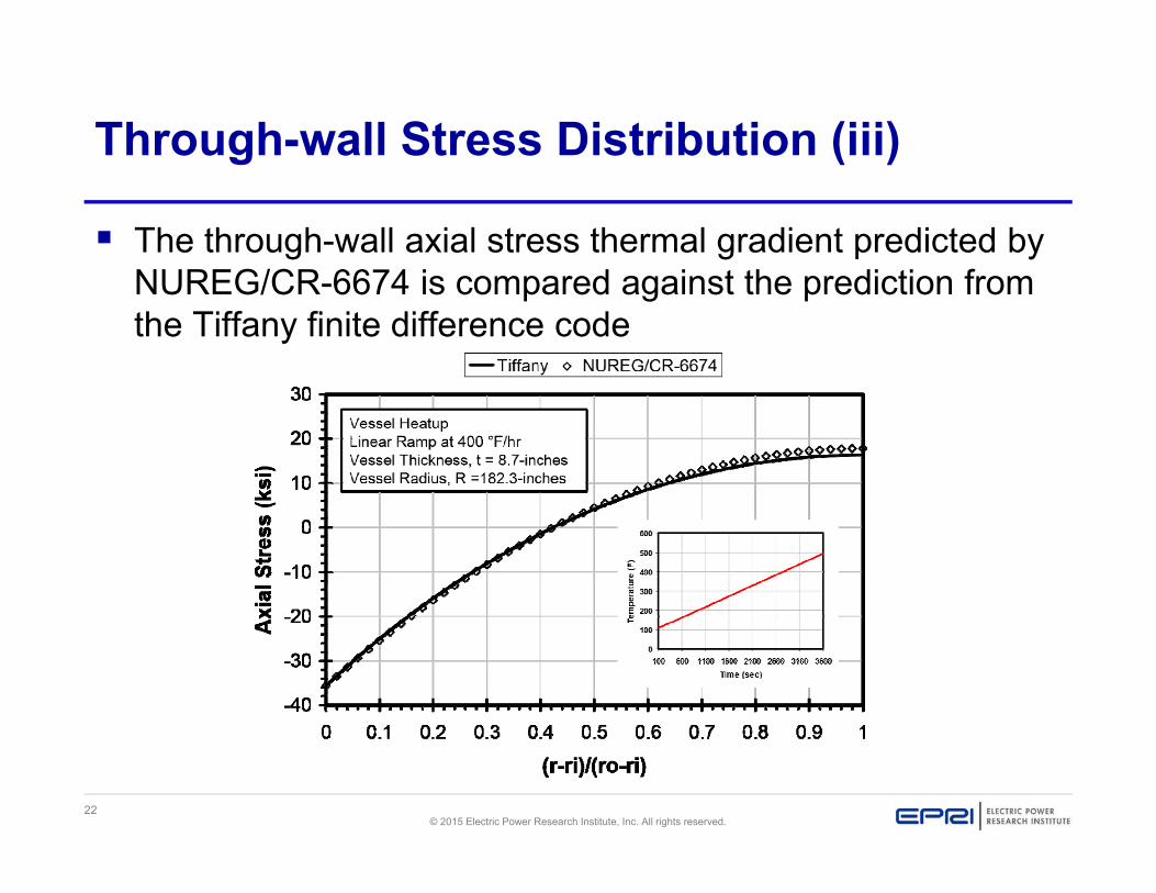
Through-wall Stress Distribution (iii)
The through-wall axial stress thermal gradient predicted by NUREG/CR-6674 is compared against the prediction from the Tiffany finite difference code

23© 2015 Electric Power Research Institute, Inc. All rights reserved.
Stress Gradient Effect
Code fatigue usage calculations apply peak stresses uniformly across the thickness.
Fatigue usage in the high strain-low cycle region are primarily driven by high peak thermal transient stresses at the inside surfaces and significant through thickness stress gradients
Crack tip stress intensities will decrease as the crack grows through the pipe wall.
Longer Stage II fatigue life results when the gradient stress is used rather than when the peak stress is applied uniformly across the thickness.

24© 2015 Electric Power Research Institute, Inc. All rights reserved.
Gradient Factor, GF
( )( ) ( )
I II Membrane
I Membrane II Gradient
N NGFN N
GF accounts for the increase in Stage II life associated with through thickness stress gradients
where:
IN = Stage 1 life between 10 m (0.0004 inch) and 200 m (0.008 inch)
IIN = Stage II life between 200 m (0.008 inch) and crack depth associated with a 25% load drop for the actual component thickness

25© 2015 Electric Power Research Institute, Inc. All rights reserved.
Size Effects
Weak link statistical size effects – In this case a larger size is expected to have an increased
probability of a weak region or flaw of a given severity being present, and hence a lowered average fatigue strength.
– Accounted for in both ASME and NUREG/CR-6909 design curves Size effects related to crack growth in larger test
specimens (Dowling 1977)– Larger specimens of identical material and applied cyclic strain tend
to have longer fatigue lives due to the increased number of cycles required to propagate a crack across the specimen.
Any improved methods of predicting size effects should address both effects

26© 2015 Electric Power Research Institute, Inc. All rights reserved.
Size Effects (ii)
Strength of material calculations were performed to estimate equivalent 25% load drop crack depths in thicker push-pull test specimens
2 1 21 1 1
2 1 22 2 2
sin ( )( )2
sin ( )( )2
YCrack Area R s s Y s RR
Ya s s Y s aa
1
2
2 2 2
22
22
1 4
Y Rs
Y as
Y a R aR

27© 2015 Electric Power Research Institute, Inc. All rights reserved.
Size Effects (iii)

28© 2015 Electric Power Research Institute, Inc. All rights reserved.
Life Factor, LF
(3 )3
25% (25%)
I II mmmm
I II
N NNLFN N N
A life factor LF corrects fatigue usage estimates for increased Stage II life associated with piping thicknesses greater than the 0.304 inch median gauge thickness associated with the NUREG/CR-6909 air test data.
IN = Stage 1 life in number of cycles between 10 m (0.0004 inch) and 200 m (0.008 inch) under uniform membrane cyclic strain
(3 )II mmN = Stage II life in number of cycles between 200 m (0.008 inch) and 3mm crack depth under uniform membrane cyclic strain
(25%)IIN = Stage II life in number of cycles between 200 m (0.008 inch) and 25% load drop crack depth under uniform membrane cyclic strain

29© 2015 Electric Power Research Institute, Inc. All rights reserved.
Stage I Life
I Total IIN N N
Assumption: Stage I initiation and growth occurs under uniform membrane loading regardless of the absence or presence of linear and non-linear through-wall stress gradients.

30© 2015 Electric Power Research Institute, Inc. All rights reserved.
Carbon Steel Pin KI*
* Forman and Shivakumar (ASTM STP 905)

31© 2015 Electric Power Research Institute, Inc. All rights reserved.
Carbon Steel Pin KJ/KI Correction
∆J is calculated using the expression for cylindrical fatigue specimens obtained by Dowling [1977]
Modified to include a geometric shape factor developed by O’Donnell and O’Donnell as referenced by Park and Chopra [2000] for crack depth approaching 40% through-wall
23.2 5
2 ( 1)pJ a a
E S
2 30.6911 1.2685 5.6638 21.511S
a a aFD D D
∆K is calculated using the pin expression developed by Forman and Shivakumar [1986]

32© 2015 Electric Power Research Institute, Inc. All rights reserved.
Carbon Steel Pin KJ/KI Correction (ii)

33© 2015 Electric Power Research Institute, Inc. All rights reserved.
Stage I - Stage II Transition = 0.575%
Temperature (°C)
1219 36.5%
Room Temp
0.304
0.008
0.118
3342
2123
2
3.00E+04
20
172.527
0.575
Node 330 Stage 1 Life = 0.575%
Initial Flaw Depth, a (inch)
Initial Aspect Ratio, L/a
Pin Diameter (inch)
Elastic Modulus (ksi)
25% Load Drop Crack Depth (inch)
Salt (ksi)
alt (%)
NUREG 6909 R1 50|50 S-N Life
Stage 1 Membrane Life
Stage II Membrane Life at 3-mm Crack Depth (Calculated)

34© 2015 Electric Power Research Institute, Inc. All rights reserved.
Stage I - Stage II Transition = 0.575% (ii)
N/Nf = 0.365
(Gavenda et al. 1997)

35© 2015 Electric Power Research Institute, Inc. All rights reserved.
Stage II Life for Pipe Crack growth of a mechanically
small crack (0.008 in.) to a crack depth associated with a 25% load drop
Crack growth calculations were performed using the NRC PRAISE computer code
PRAISE was modified to include a best estimate (50/50) of the C/LAS crack relationship in ASME Section XI
The alternating stress intensity K corrected for elastic-plastic material response in the HIGH strain LOW cycle region.

36© 2015 Electric Power Research Institute, Inc. All rights reserved.
EXAMPLE APPLICATIONBWR 4 Low Pressure Core Spray System
Reducing Elbow

37© 2015 Electric Power Research Institute, Inc. All rights reserved.
BWR 4 LPCS 10 x 12 Reducing Elbow
60 year design fatigue usage calculation at a Schedule 80 10” X 12” reducing elbow in a Low Pressure Core Spray (LPCS) system
Original calculation performed according to stress analysis procedures specified in ASME III NB-3600
The highest fatigue usage was located at Node 330 where a ¾” socket-welded elbolet is attached to Schedule 80 10” X 12” reducing elbow
The reducing elbow thickness at the location is 0.594”. 60 year fatigue usage estimates are corrected for the
component thickness and the presence of through-wall stress gradients.

38© 2015 Electric Power Research Institute, Inc. All rights reserved.
Node 330 60-yr Air and Water Fatigue Usages

39© 2015 Electric Power Research Institute, Inc. All rights reserved.
Node 330 Membrane-to-Gradient Ratios
Sp = 345.054 ksi– Sm = 61.406 ksi– Sb = 1.609 ksi– Sg = 80.161 ksi– Ke = 2.410

40© 2015 Electric Power Research Institute, Inc. All rights reserved.
Node 330 Life and Gradient Factor Calculation
Membrane m/g = 0.751
0.594 0.594
0.008 0.008
0.243 0.243
2 2
3.00E+04 3.00E+04
20 20
172.527 172.527
0.575 0.575
3342 3342
1219 12194572 6057
4934 6960
1.000 0.752
0.941 0.9410.941 0.708
Node 330 Load Set 4-6 LF and GF
LF x GF
Gradient Factor, GF
Initial Flaw Depth, a (in.)
Initial Aspect Ratio, L/a
Thickness (inch)
Elastic Modulas (ksi)
25% Load Drop Crack Depth (in.)
Temperature (°C)
Salt (ksi)
alt (%)
NUREG 6909 R1 50|50 S-N Life
Stage 1 Membane Life
Membrane Life Factor, LF
Stage 2 Life N3mm
Stage 2 Life N25%

41© 2015 Electric Power Research Institute, Inc. All rights reserved.
Node 330 Projected 60 and 80 Usage Factors
Load Set
Load Pair Fen 60-yr Air
Usage60-yr Envir
Usage 80-yr Envir
Usage LF x GFCorrected60-yr Air Usage
Corrected 60-yr Envir
Usage
Corrected 80-yr Envir
Usage1 4-6 5.972 0.1260 0.7525 1.0033 0.7080 0.0892 0.5328 0.7103
2 11-12 1.740 0.0050 0.0087 0.0116 1.0000 0.0050 0.0087 0.0116
3 11-14 1.740 0.0190 0.0331 0.0441 1.0000 0.0190 0.0331 0.0441
4 4-5 7.330 0.0010 0.0073 0.0098 1.0000 0.0010 0.0073 0.0098
5 5-14 1.740 0.0040 0.0070 0.0093 1.0000 0.0040 0.0040 0.0053
0.155 0.809 1.078 0.118 0.586 0.781CUF :

42© 2015 Electric Power Research Institute, Inc. All rights reserved.
Conclusions
Revision 1 to NUREG/CR-6909 – Updated fatigue life solutions– Test specimen gauge diameters ranged from 5.1 mm to 9.5 mm (0.2
inch to 0.375 inch). – Specimens were subjected to constant displacement cyclic loading
and failure was defined by 25% load drop. – Chopra and Stevens observed that this load drop criterion was
associated with an average 3 mm (0.118 inch) deep crack. – Independent strength of material calculations reported in this paper,
confirmed their observation. Stage I life estimates were consistent with data Results suggest that these Life and Gradient factors can result in
measurable reductions in estimated fatigue usage (especially in thicker piping).

43© 2015 Electric Power Research Institute, Inc. All rights reserved.
Together…Shaping the Future of Electricity