Fatigue Response of Ultra-High-Performance Concrete Field ...docs.trb.org/prp/11-3427.pdf ·...
16
Graybeal 1 FATIGUE RESPONSE OF AN ULTRA-HIGH PERFORMANCE CONCRETE FIELD-CAST BRIDGE DECK CONNECTION B.A. Graybeal, Ph.D., P.E. Federal Highway Administration 6300 Georgetown Pike McLean, VA 22101 (202) 493-3122 fax: (202) 493-3477 [email protected] Length = 3235 words + 8 figures + 2 tables A paper submitted for presentation at the 2011 Transportation Research Board Conference November 15, 2010 TRB 2011 Annual Meeting Paper revised from original submittal.
Transcript of Fatigue Response of Ultra-High-Performance Concrete Field ...docs.trb.org/prp/11-3427.pdf ·...

Graybeal 1
FATIGUE RESPONSE OF AN ULTRA-HIGH PERFORMANCE CONCRETE FIELD-CAST BRIDGE DECK CONNECTION
B.A. Graybeal, Ph.D., P.E. Federal Highway Administration 6300 Georgetown Pike McLean, VA 22101 (202) 493-3122 fax: (202) 493-3477 [email protected]
Length = 3235 words + 8 figures + 2 tables
A paper submitted for presentation at the 2011 Transportation Research Board Conference November 15, 2010
TRB 2011 Annual Meeting Paper revised from original submittal.

Graybeal 2
ABSTRACT The use of prefabricated concrete bridge deck components can offer many advantages
over conventional cast-in-place construction techniques. However, completing the overall bridge system requires the installation of connecting elements. The state-of-the-practice with regard to these connecting elements has been lacking in terms of resiliency, durability, and ease of construction. A research effort ongoing at the Federal Highway Administration, in conjunction with partners from the New York State and Iowa Departments of Transportation, is focused on engaging the advantageous properties of Ultra-High Performance Concrete (UHPC) to develop a new type of detail applicable to deck-level connections between prefabricated modular bridge components. This physical testing program investigated the structural performance of a field-cast UHPC connection under repeated truck wheel loading. The 150 mm (5.9 in.) thick, 152 mm (6 in.) wide connection was designed as a non-contact lap splice with straight 16M (No. 5) steel reinforcement. After over 11 million structural loading cycles at progressively increasing load levels, individual bars within the connection began to fail in metal fatigue. The stress range in the reinforcement at initial fatigue failure was conservatively estimated to be 197 MPa (28.6 ksi). No debonding or slippage of reinforcement was observed. The performance of this connection detail demonstrates the types of details that can be developed and deployed with field-cast UHPC.
TRB 2011 Annual Meeting Paper revised from original submittal.

Graybeal 3
FATIGUE RESPONSE ON AN ULTRA-HIGH PERFORMANCE CONCRETE FIELD-CAST BRIDGE DECK CONNECTION
B.A. Graybeal, Ph.D, P.E.
INTRODUCTION
The use of prefabricated concrete bridge deck components can offer many advantages over conventional cast-in-place construction techniques. However, completing the overall bridge system requires the installation of connecting elements. Many designs for these deck-level connections have been proposed, tested, and in some cases deployed in bridges around the United States. It is recognized that the state-of-the-practice with regard to deck-level connecting elements has been lacking in terms of resiliency, durability, and ease of construction. For these reasons, many bridge owners have been hesitant to embrace prefabricated bridge deck component technology even though this technology offers the potential for accelerating construction activities while increasing on-site safety.
The engagement of new concepts and new technology is needed to allow for a redesign of the connections between prefabricated elements. A research effort ongoing at the Federal Highway Administration, in conjunction with partners from the New York State and Iowa Departments of Transportation, is focused on engaging the advantageous properties of Ultra-High Performance Concrete (UHPC) to develop a new type of connection detail applicable to deck-level connections between prefabricated modular bridge components. An executive summary(1) and a full report(2) discussing the findings of this research program have recently been published.
In terms of connecting slab-type elements, one of the most common techniques is to extend reinforcing steel from each side of the previously cast elements into the non-contact lap slice connection, thereafter filling the connection with a concrete or grout. These types of connections are commonly used between both prefabricated slab elements and between cast-in-place elements constructed in stages. Given the development length of mid-steel reinforcement in these types of cementitious materials, the spliced connection is frequently quite wide and requires a large volume of field-cast fill material. Another commonly used method for connecting prefabricated elements is to use some type of confined, bolted, welded, or post-tensioned discrete connecting element within the connection.
The intent of this research program is to develop and demonstrate the structural performance of a simple connection which builds on the best concepts inherent in previously deployed connection systems while simplifying the design, easing fabrication and construction difficulties, and enhancing the long-term performance. The key to realizing acceptable structural performance with a simplified design is the significantly reduced reinforcing bar development lengths which are achieved when the advanced properties of UHPC are engaged. ULTRA-HIGH PERFORMANCE CONCRETE
The Federal Highway Administration, through its Structural Concrete Research Program, has been investigating optimal uses of UHPC in the U.S. highway bridge infrastructure. This research effort has focused on engaging the advanced properties of UHPC to address issues confronting bridge owners and constructors.
TRB 2011 Annual Meeting Paper revised from original submittal.

Graybeal 4
The term UHPC refers to a class of advanced cementitious materials. When implemented in precast construction, these concretes tend to exhibit properties including compressive strength above 150 MPa (21.7 ksi), high pre-cracking tensile strength, sustained post-cracking tensile strength through internal fiber reinforcement, and exceptional durability(3). The specific UHPC investigated in this study is a product of a major worldwide construction materials manufacturer and supplier. It is currently the only product of this type that is widely available in the U.S. in the quantities necessary for large scale infrastructure applications. European and Asian markets currently have multiple suppliers, and a similar situation will likely occur in the U.S. as the market for this type of advanced cementitious product develops.
The composition of this UHPC includes four granular constituents. Fine sand, generally between 150 and 600 µm (0.006 and 0.024 in.), is the largest granular material. The next largest particle is cement with an average diameter of approximately 15 µm (0.0006 in.). Of similar size is the crushed quartz with an average diameter of 10 µm (0.0004 in.). The smallest particle, the silica fume, has a diameter small enough to fill the interstitial voids between the cement and the crushed quartz particles. Dimensionally, the largest constituent in the mix is the steel fiber reinforcement. In this study, the fibers in the mix had a diameter of 0.2 mm (0.008 in.), a length of 12.7 mm (0.5 in.), and a minimum tensile strength of 2,000 MPa (290 ksi). The fibers were included in the mix at two percent by volume. The typical mix composition of the UHPC used in this study, including the polycarboxylate-based superplasticizer, is provided in Table 1.
Table 1. Typical field-cast UHPC mix composition.
Material Amount (kg/m3 (lb/yd3)) Percent by Weight Portland Cement 712 (1,200) 28.6 Fine Sand 1,020 (1,720) 41.0 Silica Fume 231 (390) 9.3 Ground Quartz 211 (355) 8.5 Superplasticizer 30 (51) 1.2 Steel Fibers 156 (263) 6.2 Water 130 (218) 5.2 A previous study investigated the basic material properties of the type of UHPC studied
herein.(1) Table 2 lists some of the properties relevant to this UHPC in a field-cast situation. Of note, this study reported a high compressive strength, high stiffness, high tensile strength, and low chloride ion penetrability. FIELD-CAST UHPC CONNECTION DETAILS
The concept of using the advanced properties of UHPC to significantly modify the design of connections between precast concrete components is not new. In fact, research and deployments in this area date back to at least 1995.(4) At that time, two projects were completed at Aalborg University in Denmark wherein a commercially available UHPC was used as a closure fill material in the connection of slab elements in a building. In association with these projects, a series of studies on the bonding performance between UHPC and straight lengths of mild steel reinforcement were completed at Chalmers University in Sweden.
TRB 2011 Annual Meeting Paper revised from original submittal.

Graybeal 5
Table 2. Typical field-cast UHPC material properties.
Material Characteristic Average Result Density 2,480 kg/m3 (155 lb/ft3) Compressive Strength (ASTM C39; 28-day strength) 126 MPa (18.3 ksi) Modulus of Elasticity (ASTM C469; 28-day modulus) 42.7 GPa (6200 ksi) Split Cylinder Cracking Strength (ASTM C496) 9.0 MPa (1.3 ksi) Prism Flexure Cracking Strength (ASTM C1018; 305-mm (12-in.) span) 9.0 MPa (1.3 ksi) Mortar Briquette Cracking Strength (AASHTO T132) 6.2 MPa (0.9 ksi) Direct Tension Cracking Strength (Axial tensile load) 5.5–6.9 MPa (0.8–1.0 ksi) Prism Flexural Tensile Toughness (ASTM C1018; 305-mm (12-in.) span) I30 = 48 Long-Term Creep Coefficient (ASTM C512; 77 MPa (11.2 ksi) load) 0.78 Long-Term Shrinkage (ASTM C157; initial reading after set) 555 microstrain Total Shrinkage (Embedded vibrating wire gage) 790 microstrain
Coefficient of Thermal Expansion (AASHTO TP60–00) 14.7 x10⁻⁶ mm/mm/ºC (8.2 x10⁻⁶ in./in./ºF)
Chloride Ion Penetrability (ASTM C1202; 28-day test) 360 coulombs Chloride Ion Permeability (AASHTO T259; 12.7-mm (0.5-in.) depth) < 0.06 kg/m3 (< 0.10 lb/yd3) Scaling Resistance (ASTM C672) No Scaling Abrasion Resistance (ASTM C944 2x weight; ground surface) 0.73 grams lost (0.026 oz. lost) Freeze-Thaw Resistance (ASTM C666A; 600 cycles) RDM = 112%
Alkali-Silica Reaction (ASTM C1260; tested for 28 days) Innocuous
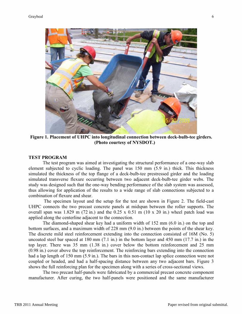
More recently, the concept of using the properties of UHPC to redesign the connections between modular bridge components has been recognized in North America. As of late 2010, field-cast UHPC connections between prefabricated bridge components have been implemented in nine bridges in Canada and two in the United States. These bridges use a range of details to connect a variety of different precast concrete modular bridge components, including adjacent box beams, full-depth precast deck panels, and deck-bulb-tee girders. The connection designs deployed to date have tended to mimic non-contact lap splice connections with a female-female shear key profile. Figure 1 shows the casting of the UHPC into the longitudinal connection between the top flanges of deck-bulb-tee girders. This bridge, constructed by the New York State Department of Transportation (NYSDOT), opened to traffic in 2009.
The two fundamental differences between the field-cast UHPC connection concept and conventional modular component connection concepts are simplicity and performance. The UHPC connection concept allows for small, simple connections without requiring the use of post-tensioning, complex confinement details, or large volumes of field-cast concrete. The performance of the connection exceeds that normally anticipated from a field-cast connection, thus allowing the joined components to emulate or surpass the behavior of monolithic construction.
TRB 2011 Annual Meeting Paper revised from original submittal.
Graybeal 6
Figure 1. Placement of UHPC into longitudinal connection between deck-bulb-tee girders. (Photo courtesy of NYSDOT.)
TEST PROGRAM The test program was aimed at investigating the structural performance of a one-way slab
element subjected to cyclic loading. The panel was 150 mm (5.9 in.) thick. This thickness simulated the thickness of the top flange of a deck-bulb-tee prestressed girder and the loading simulated transverse flexure occurring between two adjacent deck-bulb-tee girder webs. The study was designed such that the one-way bending performance of the slab system was assessed, thus allowing for application of the results to a wide range of slab connections subjected to a combination of flexure and shear.
The specimen layout and the setup for the test are shown in Figure 2. The field-cast UHPC connects the two precast concrete panels at midspan between the roller supports. The overall span was 1.829 m (72 in.) and the 0.25 x 0.51 m (10 x 20 in.) wheel patch load was applied along the centerline adjacent to the connection.
The diamond-shaped shear key had a uniform width of 152 mm (6.0 in.) on the top and bottom surfaces, and a maximum width of 228 mm (9.0 in.) between the points of the shear key. The discrete mild steel reinforcement extending into the connection consisted of 16M (No. 5) uncoated steel bar spaced at 180 mm (7.1 in.) in the bottom layer and 450 mm (17.7 in.) in the top layer. There was 35 mm (1.38 in.) cover below the bottom reinforcement and 25 mm (0.98 in.) cover above the top reinforcement. The reinforcing bars extending into the connection had a lap length of 150 mm (5.9 in.). The bars in this non-contact lap splice connection were not coupled or headed, and had a half-spacing distance between any two adjacent bars. Figure 3 shows the full reinforcing plan for the specimen along with a series of cross-sectional views.
The two precast half-panels were fabricated by a commercial precast concrete component manufacturer. After curing, the two half-panels were positioned and the same manufacturer
TRB 2011 Annual Meeting Paper revised from original submittal.

Graybeal 7
mixed and cast the UHPC between them. No special curing regimes were applied to the precast panels or the field-cast UHPC.
Electronic gage-based and visual observations were collected periodically during the cycling. Five electrical resistance strain gages were affixed to the surface of the specimen, all along the centerline of the panel. These gages included one above and below the panel at midspan, one above and below at 0.25 m (10 in.) south of the connection, and one below at 0.25 m (10 in.) north of the connection. An LVDT was also attached over a 0.25 m (10 in.) gage length, spanning the connection at midspan. The load and stroke of the actuator were also monitored throughout the test. Finally, water was ponded on top of the connection throughout the cyclic loading to provide a clear indication of connection water-tightness.
The cyclic testing was completed over the course of 3 months. Computer-controlled servo-hydraulic actuators applied the load vertically downward on the deck through a steel plate sitting on an elastomeric bearing pad. The sinusoidal cyclic loading was applied at frequencies of 6 Hz or less depending on the stiffness of the specimen, with the lowest frequencies occurring as the specimen was nearing failure. An overhead view of the cyclic loading of the deck specimen is shown in Figure 4.
TRB 2011 Annual Meeting Paper revised from original submittal.

Graybeal 8
Figure 2. Test setup for cyclic loading of field-cast UHPC deck connection specimen.
2.152 m
LOAD
Supp
ort
1.829 m
150 mm
2.4 m
(84.7 in.) (72 in.)
(94.5 in.)
(5.9 in.)
LOAD
North
Edge
Strain Gage(below only)
Strain Gage (above and below)
LVDT attachments(underside only)
CenterlineCenterline
Midspan
MidspanWest Edge
Supp
ort
TRB 2011 Annual Meeting Paper revised from original submittal.

Graybeal 9
Figure 3. Reinforcement plan for field-cast UHPC deck connection specimen.
2152 mm
2400
mm
152 mm
150 mm(5.9 in.) lap length
(6.0 in.) connection width
150 mm(5.9 in.)
7'-1
"(5
) 16M
(#5)
@ 4
50 m
m (1
7.7
in.)
spac
ing (
TOP)
(13)
16M
(#5)
@ 1
80 m
m (7
.1 in
.) sp
acin
g (BO
TTOM
)
2'-11"2'-11"
(5) 16M (#5) @ 225 mm (8.9 in.) spacing (TOP & BOTTOM)
7'-8
"(6
) 16M
(#5)
@ 4
50 m
m (1
7.7
in.)
spac
ing (
TOP)
(14)
16M
(#5)
@ 1
80 m
m (7
.1 in
.) sp
acin
g (BO
TTOM
)
(2) 16M (#5)
A A
B
B
Section A-A
Section B-B
Section C-C
B
B C
C
(84.7 in.)
(94.
5 in
.)
TRB 2011 Annual Meeting Paper revised from original submittal.

Graybeal 10
Figure 4. Overhead view of test setup for cyclic testing of panel.
TEST RESULTS Prior to the start of testing, the panel was assessed to verify that it did not contain any
significant cracking. Aside from tight, distributed shrinkage cracking in the precast panels, no cracking was observed in the specimen. The initial loading of the specimen covered a load range from 8.9 to 71.2 kN (2 to 16 kips). The first load applied over this range resulted in flexural cracking of the north precast panel. After removing the load, these three cracks were measured to have widths varying from 0.025 to 0.152 mm (0.001 to 0.006 in.). No cracks were observed in the UHPC or at the connection interfaces.
After 57,300 cycles had been applied at a frequency of 6 Hz, an actuator malfunction resulted in a sustained load of 311 kN (70 kips) being applied to the specimen. This load resulted in significant cracking of the precast panels, of the field-cast UHPC, and at the connection interfaces. Figure 5 shows the cracking that was apparent on the underside of the specimen after this overload was removed. The cracking in the precast panels was measured to have widths in the vicinity of 0.25 to 0.51 mm (0.010 to 0.020 in.). Note that the flexural cracking along the connection interfaces was observed to extend along approximately 80 percent of the total interface length, with the remainder of the length being covered by cracks which diverged into the precast panels.
Given that the panel had already been subjected to significant cracking, the planned additional cycles peaking at 71.2 kN (16 kips) were cancelled and the load level was increased for the remainder of the cyclic loading. The cyclic load range was increased to 13.3 to 95 kN (3 to 21.3 kips) and this load range was applied to the specimen at a frequency of 5 Hz. This cycling was continued for a total of 10,096,700 cycles. Periodically throughout and again at the conclusion of these cycles, the crack pattern observed on the underside of the panel was recorded. No significant changes were observed in the crack locations or widths during these cycles, thus Figure 5 again presents the crack pattern. At the conclusion of these cycles, the connection interfaces remained water-tight.
TRB 2011 Annual Meeting Paper revised from original submittal.

Graybeal 11
Figure 5. Cracking pattern observed on underside of panel after initial overload and again after 10.1 million cycles of loading from 13 to 95 kN (3 to 21.3 kips).
Given that over 10 million cycles of loading had not resulted in any apparent progressive degradation of the connection, the load range was increased to cover the range from 13.3 to 142.3 kN (3 to 32 kips). To achieve these loads, the frequency was decreased to 3 Hz. This loading was applied for a total of 1,118,000 cycles. Cracking was again assessed at the conclusion of these cycles. Although no additional significant cracking was observed, some precast panel crack widths had increased. Also, the interface cracking had progressed up through the cross section and minor water leakage along cracks near the interface was observed.
Finally, a load range of 13.3 to 177.9 kN (3 to 40 kips) was applied for a total of 343,399 cycles. During the final cycle, the specimen deflected excessively and the peak load
Rolle
r Sup
port
Rolle
r Sup
port
LoadPatch
UHPC
Conn
ectio
n
Prec
ast P
anel
Prec
ast P
anel
North
Edg
eEast Edge
HPC CracksUHPC CracksInterface Cracks
TRB 2011 Annual Meeting Paper revised from original submittal.

Graybeal 12
could not be reached. The south interface from the centerline to the west side of the specimen was observed to be fully disconnected. Cyclic loading was ceased and a static load was applied to pry the specimen apart along the south interface failure plane. Sounds corresponding to the fracture of two reinforcing bars were heard during this static loading. Another five bars were manually cut with a torch in order to separate the north panel and field-cast UHPC from the south panel at the connection interface. Figure 6 shows the east elevation of the panel after the conclusion of cyclic loading and prior to the cutting of the remaining bars.
Figure 6. Panel after the conclusion of cyclic loading.
The responses captured by the electronic gages during the final three sets of cyclic loading are presented in Figure 7. This figure shows the strain per applied load in three strain gages, the stroke range per cycle, and the connection opening per cycle as captured by the LVDT. Note that the LVDT values are inclusive of both opening across interface cracks as well as straining of concrete between the LVDT attachment points. These results show that the response of the panel stabilized during the 10.1 million cycles and again during the subsequent 1.1 million cycles. However, the response did not stabilize and the panel progressively degraded until failure occurred during the final 0.34 million cycles at the highest load range.
Separation of the two specimen remnants after the completion of cyclic testing allowed for a clear view of the interface and the crossing reinforcing bars. Of the 18 reinforcing bars crossing the interface, five were torch cut and four were fractured with no indication of post-fracture impact by the mating bar surface. The remaining nine bars had fractured prior to the cessation of cyclic loading and showed signs of post-fracture impact with their mating bar surface. Mating surfaces were observed on each side of the interface for every bar, and there was no indication that any of the reinforcing bars debonded either within the connection or within the panel. Figure 8 shows the cross section of the interface with the reinforcing bars and the failure mechanisms noted. This figure also shows photographs of four of the reinforcing bar tips, one of which represents a fracture surface and three of which represent bars that fractured then were impacted by their mating surfaces after fracture.
A cracked-section analysis of the specimen was completed to assess the stress range in the reinforcing bars at the connection during the cyclic loading. Given that the analysis assumed
TRB 2011 Annual Meeting Paper revised from original submittal.

Graybeal 13
one-way bending and uniform distribution of load across the width of the specimen, the actual stresses in the bars near the middle of the deck were likely higher. During the loading which peaked at 95 kN (21.3 kips), the stress range in the bottom layer of reinforcing bar was calculated to be 98 MPa (14.2 ksi). During the loading which peaked at 142.3 kN (32 kips), the corresponding stress range was calculated to be 155 MPa (22.5 ksi). During the final cyclic loading to 177.9 kN (40 kips), the stress range in the bottom layer of reinforcing bar at the failure location was calculated to be 197 MPa (28.6 ksi). Prior work on fatigue of mild steel reinforcing bar has indicated that stress range is the primary factor in tensile fatigue fracture of reinforcing bars and that a stress range of 197 MPa (28.6 ksi) should result in a finite fatigue life.(4)
TRB 2011 Annual Meeting Paper revised from original submittal.

Graybeal 14
Figure 7. Cyclic test results.
-22.2-17.8-13.3-8.9-4.40.04.48.913.317.822.2
-5-4-3-2-1012345
0 2 4 6 8 10 12
Stra
in pe
r App
lied L
oad (
µε/k
ip)
m
Stra
in pe
r App
lied L
oad (
µε/k
N)
m
Millions of Cycles of Structural Loading
Tensile Face of ConnectionCompression Face, 254 mm (10 in.) from ConnectionCompression Face of Connection
0.16
0.31
0.47
0.63
0.79
4.0
8.0
12.0
16.0
20.0
Stro
ke R
ange
(in.
)m
Stro
ke R
ange
(mm
) m
Actuator displacement range per cycle.
0.0000
0.0018
0.0035
0.0053
0.0070
0.0088
0.0105
0.000
0.010
0.020
0.030
0.040
0.050
0.060
Conn
ectio
n Ope
ning
(in.
/kip
)m
Conn
ectio
n Ope
ning
(mm
/kN
) m
Applied Load Range13 to 95 kN(3 to 21.3 kips)
13 to 178 kN (3 to 40 kips)13 to 142 kN (3 to 32 kips)
Measured via LVDT on 254 mm (10 in.) gage length across connection inclusive of incorporated strain.
TRB 2011 Annual Meeting Paper revised from original submittal.

Graybeal 15
Figure 8. Diagram of cross section with identification of reinforcing bar failure type and illustrative photos.
CONCLUSIONS The use of prefabricated concrete bridge deck components offers many advantages over
conventional cast-in-place construction techniques; however, the deck-level connections between these elements have many times proven to be lacking in terms of resiliency, durability, and ease of construction. The study discussed herein investigated the performance of a simple, novel connection design which engaged the advanced properties of UHPC to simplify design and enhance performance. The physical testing program investigated the structural performance of a non-contact lap splice connection constructed with UHPC and subjected to repeated truck wheel loading. The 150 mm (5.9 in.) thick, 152 mm (6 in.) wide connection included straight uncoated 16M (No. 5) steel reinforcement.
The study demonstrated that the discrete reinforcement in the UHPC-filled non-contact lap splice connection was not susceptible to debonding from the UHPC under conditions such as applied in this test program. The specimen was subjected to a large static overload and then 11.5 million subsequent cycles of structural loading at increasing load levels. The crack pattern observed on the underside of this specimen immediately after the overload did not change throughout the subsequent cycling. The overload and subsequent cycling were not observed to cause any debonding of the straight lengths of rebar that were lapped across the connection.
The development length of straight, uncoated 16M (No. 5) mild steel reinforcing bars was demonstrated to be equal to or less than 150 mm (5.9 inches) in a non-contact lap splice configuration within a field-cast UHPC-filled connection when subjected to flexural tensile loads. The cyclic loading demonstrated that when sufficiently large amplitude cyclic loads are applied, the stress range in the rebar can be sufficient to force the rebar to fail via metal fatigue.
In total, the research presented herein, the research presented in the associated testing report(2), and the practical experience gained through field-deployments of this technology in New York and Ontario have demonstrated the viability of the field-cast UHPC connection system for precast modular bridge deck components. ACKNOWLEDGEMENT
The research which is the subject of this paper was completed through Transportation Pooled Fund Study TPF-5(217): “Ultra-High Performance Connections Between Precast Bridge
TRB 2011 Annual Meeting Paper revised from original submittal.

Graybeal 16
Deck Elements”. This research was conducted by the Federal Highway Administration and was supported by contributions from the New York State Department of Transportation and the Iowa Department of Transportation. The publication of this article does not necessarily indicate approval or endorsement by the study partners, the Federal Highway Administration, or the United States Government of the findings, opinions, conclusions, or recommendations either inferred or specifically expressed herein. REFERENCES 1. Graybeal, B., “Field-Cast UHPC Connections for Modular Bridge Deck Elements,” FHWA
Report HRT-11-022, Nov. 2010, 8 pp.
2. Graybeal, B., “Behavior of Field-Cast Ultra-High Performance Concrete Bridge Deck Connections Under Cyclic and Static Structural Loading,” NTIS Report No. PB2011-101995, Nov. 2010, 106 pp.
3. Graybeal, B., “Material Property Characterization of Ultra-High Performance Concrete,” Federal Highway Administration, Report No. FHWA-HRT-06-103, August 2006, 186 pp.
4. Hansen, L., and Jensen, B. (1999). “A New Building System Using Joints of Ultra High-Strength Fibre Reinforced Concrete,” Innovation in Concrete Structures: Design and Construction: Proceedings of the International Conference on Creating with Concrete, University of Dundee, Scotland, pp.543-552.
5. Helgason, T., J. Hanson, N. Somes, W. G. Corley, and E. Hognestad, “Fatigue Strength of High-Yield Reinforcing Bars,” Portland Cement Association Research and Development Bulletin RD045.01E, 1976.
TRB 2011 Annual Meeting Paper revised from original submittal.