fatigue is the weakening of a material caused by ... · PDF filefatigue is the weakening of a...
78
Why things fail fatigue is the weakening of a material caused by repeatedly applied loads
Transcript of fatigue is the weakening of a material caused by ... · PDF filefatigue is the weakening of a...
Why things fail
fatigue is the weakening of a material caused by repeatedly applied loads

Macroscopic and microscopic discontinuities as well as component design features which cause stress concentrations (holes, keyways, sharp changes of direction etc.) are common locations at which the fatigue process begins.

Fatigue is a process that has a degree of randomness (stochastic), often showing considerable scatter even in well controlled environments. Fatigue is usually associated with tensile stresses but fatigue cracks have been reported due to compressive loads.[7] The greater the applied stress range, the shorter the life. Fatigue life scatter tends to increase for longer fatigue lives.
Fatigue life scatter tends to increase for longer fatigue lives. Damage is cumulative. Materials do not recover when rested. Fatigue life is influenced by a variety of factors, such as temperature, surface finish, metallurgical microstructure, presence of oxidizing or inert chemicals, residual stresses, scuffing contact (fretting), etc. Some materials (e.g., some steel and titanium alloys) exhibit a theoretical fatigue limit below which continued loading does not lead to fatigue failure.

Cyclic stress state: Depending on the complexity of the geometry and the loading, one or more properties of the stress state need to be considered, such as stress amplitude, mean stress, biaxiality, in-phase or out-of-phase shear stress, and load sequence, Geometry: Notches and variation in cross section throughout a part lead to stress concentrations where fatigue cracks initiate. Surface quality: Surface roughness can cause microscopic stress concentrations that lower the fatigue strength. Compressive residual stresses can be introduced in the surface by e.g. shot peening to increase fatigue life. Such techniques for producing surface stress are often referred to as peening, whatever the mechanism used to produce the stress. Low plasticity burnishing, laser peening, and ultrasonic impact treatment can also produce this surface compressive stress and can increase the fatigue life of the component. This improvement is normally observed only for high-cycle fatigue.
Material Type: Fatigue life, as well as the behavior during cyclic loading, varies widely for different materials, e.g. composites and polymers differ markedly from metals. Residual stresses: Welding, cutting, casting, grinding, and other manufacturing processes involving heat or deformation can produce high levels of tensile residual stress, which decreases the fatigue strength. Size and distribution of internal defects: Casting defects such as gas porosity voids, non-metallic inclusions and shrinkage voids can significantly reduce fatigue strength. Air or Vacuum: Certain materials like Metals are more prone to fatigue in air than in a vacuum. Depending upon the level of humidity and temperature, the lifetime for metals such as aluminum or iron might be as much as 5 to 10 times greater in a vacuum. This is mostly due to the effect of the oxygen and water vapour in the air which will aggressively attack the material and so encourage the propagation of cracks. Other environments such as oil or seawater may reduce the fatigue life at an even greater rate.
Direction of loading: For non-isotropic materials, fatigue strength depends on the direction of the principal stress. Grain size: For most metals, smaller grains yield longer fatigue lives, however, the presence of surface defects or scratches will have a greater influence than in a coarse grained alloy. Environment: Environmental conditions can cause erosion, corrosion, or gas-phase embrittlement, which all affect fatigue life. Corrosion fatigue is a problem encountered in many aggressive environments. Temperature: Extreme high or low temperatures can decrease fatigue strength. Crack Closure: Crack closure is a phenomenon in fatigue loading, during which the crack will tend to remain in a closed position even though some external tensile force is acting on the material. During this process the crack will open only at a nominal stress above a particular crack opening stress. This is due to several factors such as plastic deformation or phase transformation during crack propagation, corrosion of crack surfaces, presence of fluids in the crack, or roughness at cracked surfaces etc. this will provide a longer fatigue life for the material than expected, by slowing the crack growth rate

Design against fatigue Dependable design against fatigue-failure requires thorough education and supervised experience in structural engineering, mechanical engineering, or materials science. There are four principal approaches to life assurance for mechanical parts that display increasing degrees of sophistication:
Design to keep stress below threshold of fatigue limit (infinite lifetime concept); fail-safe, graceful degradation, and fault-tolerant design: Instruct the user to replace parts when they fail. Design in such a way that there is no single point of failure, and so that when any one part completely fails, it does not lead to catastrophic failure of the entire system.

Safe-life design: Design (conservatively) for a fixed life after which the user is instructed to replace the part with a new one (a so-called lifed part, finite lifetime concept, or "safe-life" design practice); planned obsolescence and disposable product are variants that design for a fixed life after which the user is instructed to replace the entire device; damage tolerant design: Instruct the user to inspect the part periodically for cracks and to replace the part once a crack exceeds a critical length. This approach usually uses the technologies of nondestructive testing and requires an accurate prediction of the rate of crack-growth between inspections. The designer sets some aircraft maintenance checks schedule frequent enough that parts are replaced while the crack is still in the "slow growth" phase. This is often referred to as damage tolerant design or "retirement-for-cause".

Stopping fatigue Fatigue cracks that have begun to propagate can sometimes be stopped by drilling holes, called drill stops, in the path of the fatigue crack. This is not recommended as a general practice because the hole represents a stress concentration factor which depends on the size of the hole and geometry, though the hole is typically less of a stress concentration than the removed tip of the crack. The possibility remains of a new crack starting in the side of the hole. It is always far better to replace the cracked part entirely.

Material change Changes in the materials used in parts can also improve fatigue life. For example, parts can be made from better fatigue rated metals. Complete replacement and redesign of parts can also reduce if not eliminate fatigue problems. Thus helicopter rotor blades and propellers in metal are being replaced by composite equivalents. They are not only lighter, but also much more resistant to fatigue. They are more expensive, but the extra cost is amply repaid by their greater integrity, since loss of a rotor blade usually leads to total loss of the aircraft. A similar argument has been made for replacement of metal fuselages, wings and tails of aircraft.[19]

High Frequency Mechanical Impact (HFMI) treatment of welds The durability and life of dynamically loaded, welded steel structures are determined often by the welds, particular by the weld transitions. By selective treatment of weld transitions with the High Frequency Mechanical Impact (HFMI) treatment method, the durability of many designs can be increased significantly. This method is universally applicable, requires only technical equipment and offers high reproducibility and a high grade of quality control.


Type of Failure The major types of failures likely to be encountered by metals in service are: A. Ductile, B. Brittle, and C. Fatigue fractures
A. Ductile Fracture Ductile fractures are characterized by tearing of metal accompanied by appreciable gross plastic deformation. The microstructure of the fracture surface is quite complex and may include both transgranular and intergranular fracture mechanisms. Ductile fractures in most metals have a gray fibrous appearance and may be flat-faced (tensile overload) or slant-faced (shear). The specimen usually shows considerable elongation and possible reduction of cross-sectional area as well.

Whether a part fails in a ductile or brittle fashion depends on the thickness of the part, temperature, strain rate and the presence of stress-raisers. Most commonly seen characteristics of ductile failures are: • Lateral contraction, or necking; • Fracture path in the interior following a generally flat plane perpendicular to the principal stress direction, and • Tensile stress.
B. Brittle Fracture Brittle fractures are characterized by rapid crack propagation without appreciable plastic deformation. If brittle fractures occur across particular crystallographic planes they are called Tran crystalline fracture. If along grain boundaries they are called intergranular fracture. Brittle fracture is promoted by: • thicker section sizes, • lower service temperatures, and • increased strain rate.

C. Fatigue fracture Fatigue is a progressive localized permanent structural change that occurs in a material subjected to repeated or fluctuating stresses well below the ultimate tensile strength (UTS). Fatigue fractures are caused by the simultaneous action of cyclic stress, tensile stress, and plastic strain, all three of which must be present. Cyclic stress initiates a crack and tensile stress propagates it. Final sudden failure of the remaining cross-section occurs by either shear or brittle fracture. Striations on the crack surface are the classic sign of fatigue fracture.

High Cycle Fatigue Low Cycle Fatigue Fatigue cracks may start because of tool marks, scratches, indentations, corrosion pits and areas of high stress. At the crack tip, the material is plastic. At a small distance from the crack tip, in the material is elastic
Low cycle fatigue cracks occur under conditions of high strain amplitude (with failure in less than about 104 cycles) whereas high cycle fatigue occurs with low strain amplitude with failure after a large number of load fluctuations.

Thermal Fatigue cracking is caused by cycling the temperature of the part in the presence of mechanical constraint, e.g., rigid mounting of pipe. It could also be caused by temperature gradients in the part.
Contact Fatigue - Elements that roll, or roll and slide against each other under high contact pressure are subject to the development of surface pits or fatigue spalls after many repetitions of load.

Corrosion pit acting as stress concentrator for fatigue crack

Liquid Metal Embrittlement Liquid metal embrittlement is the decrease in ductility of a metal caused by contact with liquid metal. The decrease in ductility can result in catastrophic brittle failure of a normally ductile material. Very small amounts of liquid metal are sufficient to result in embrittlement.

Some events that may permit liquid metal embrittlement under the appropriate circumstances are listed below: Brazing Soldering Welding Heat treatment Hot working Elevated temperature service In addition to an event that will allow liquid metal embrittlement to occur, it is also required to have the component in contact with a liquid metal that will embrittle the component.

Liquid Metal Embrittlement Failures The liquid metal can not only reduce the ductility but significantly reduce tensile strength. Liquid metal embrittlement is an insidious type of failure as it can occur at loads below yield stress. Thus, catastrophic failure can occur without significant deformation or obvious deterioration of the component
Corrosion is is a normal, natural process. Corrosion can seldom be totally prevented, but it can be minimized or controlled by proper choice of material, design, coatings, and occasionally by changing the environment. Various types of metallic and nonmetallic coatings are regularly used to protect metal parts from corrosion.

Corrosion Failures
Corrosion is chemically induced damage to a material that results in deterioration of the material and its properties. This may result in failure of the component. Several factors should be considered during a failure analysis to determine the affect corrosion played in a failure.

Examples are listed below: • Type of corrosion • Corrosion rate • The extent of the corrosion • Interaction between corrosion and other failure mechanisms


Stress corrosion cracking necessitates a tensile stress, which may be caused by residual stresses, and a specific environment to cause progressive fracture of a metal. Aluminum and stainless steel are well known for stress corrosion cracking problems. However, all metals are susceptible to stress corrosion cracking in the right environment.
Corrosion Failures Analysis Identification of the metal or metals, environment the metal was subjected to, foreign matter and/or surface layer of the metal is beneficial in failure determination.

Examples of some common types of corrosion are listed below: • Uniform corrosion • Pitting corrosion • Intergranular corrosion • Crevice corrosion • Galvanic corrosion • Stress corrosion cracking Not all corrosion failures need a comprehensive failure analysis. At times a preliminary examination will provide enough information to show a simple analysis is adequate.

High Temperature Failure Analysis Creep occurs under load at high temperature. Boilers, gas turbine engines, and ovens are some of the systems that have components that experience creep Failures involving creep are usually easy to identify due to the deformation that occurs. Failures may appear ductile or brittle. Cracking may be either transgranular or intergranular

Hydrogen Embrittlement When tensile stresses are applied to a hydrogen embrittled component it may fail prematurely. Hydrogen embrittlement failures are frequently unexpected and sometimes catastrophic. An externally applied load is not required as the tensile stresses may be due to residual stresses in the material. The threshold stresses to cause cracking are commonly below the yield stress of the material. High strength steel, such as quenched and tempered steels or precipitation hardened steels are particularly susceptible to hydrogen embrittlement.

Very small amounts of hydrogen can cause hydrogen embrittlement in high strength steels. Common causes of hydrogen embrittlement are pickling, electroplating and welding, however hydrogen embrittlement is not limited to these processes. Hydrogen embrittlement is an insidious type of failure as it can occur without an externally applied load or at loads significantly below yield stress. While high strength steels are the most common case of hydrogen embrittlement all materials are susceptible.

Ductile Fractures Ductile fracture is characterized by tearing of metal and significant plastic deformation. The ductile fracture may have a gray, fibrous appearance. Ductile fractures are associated with overload of the structure or large discontinuities.

Ductile and Brittle Metal Characteristics Ductile metals experience observable plastic deformation prior to fracture. Brittle metals experience little or no plastic deformation prior to fracture
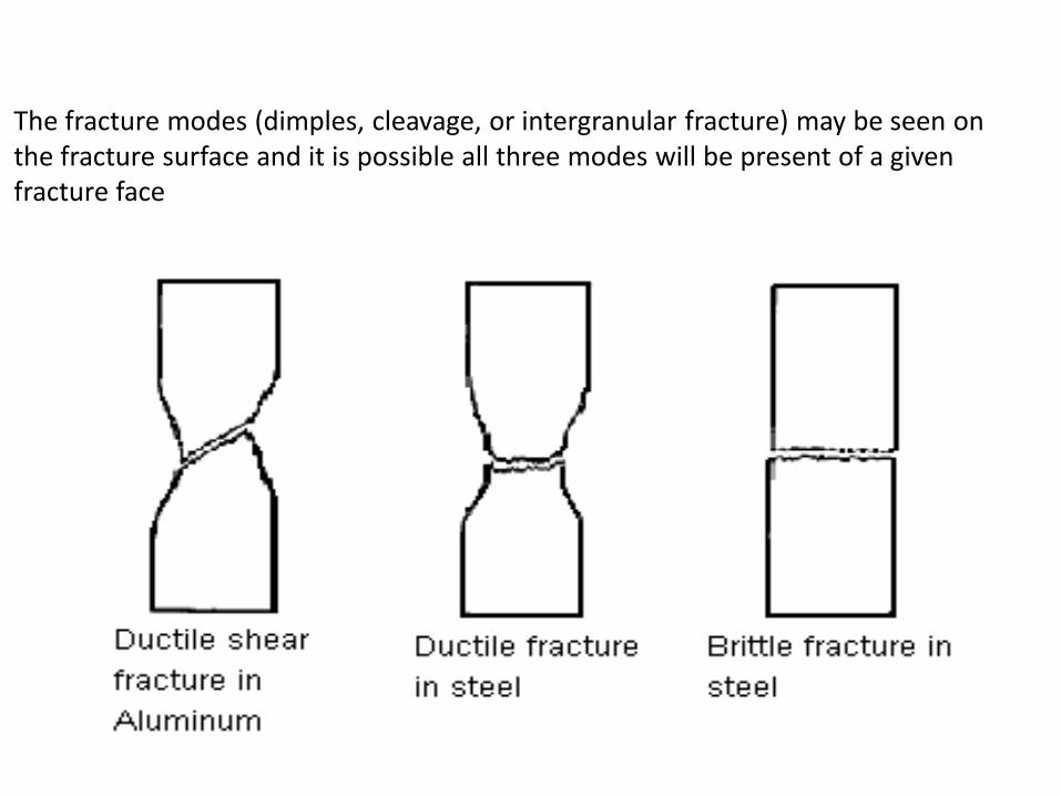
The fracture modes (dimples, cleavage, or intergranular fracture) may be seen on the fracture surface and it is possible all three modes will be present of a given fracture face

Brittle Fractures Brittle fracture is characterized by rapid crack propagation with low energy release and without significant plastic deformation. The fracture may have a bright granular appearance. The fractures are generally of the flat type and chevron patterns may be present.

Residual Stresses Residual stresses can be sufficient to cause a metal part to suddenly split into two or more pieces after it has been resting on a table or floor without external load being applied. While this is not a common occurrence, experienced people in the metal working industry have witnessed this phenomenon. While there may be additional factors causing this to occur residual stresses help explain these occurrences.
Residual stresses are stresses that are inside or locked into a component or assembly of parts. The internal state of stress is caused by thermal and/or mechanical processing of the parts. Common examples of these are bending, rolling or forging a part. Another example are the thermal stresses induced when welding.

Stress Concentration The image at the right shows the concept of stress concentration at the root of the notch on the left. The image on the right shows a uniform stress field represented as imaginary uniform stress lines that concentrate in intensity at the root of the notch. Stress concentrations may permit failure modes to occur more quickly in fatigue, stress corrosion cracking, creep

Marine Corrosion Marine corrosion includes the immersion of components in a seawater, equipment and piping that use seawater or brackish water, and corrosion in marine atmospheres. Exposure of components can be continuous or intermittent. Ships, marinas, pipelines, offshore structures, desalination plants, and heat exchangers are some examples of systems that experience marine corrosion.

Corrosion of a component, such as a bolt, can vary markedly depending on if it is simply in a marine atmosphere, a splash zone, or submerged in seawater.

Marine atmospheres are generally considered to be one of the more aggressive atmospheric corrosion environments. Some factors that affect corrosion rates in marine atmospheres are listed below: • Humidity • Wind • Temperature • Airborne contaminants • Location • Biological organisms
Cathodic protection can be accomplished by either using an impressed current system or by using sacrificial anode system. Magnesium, aluminum and zinc alloys are the most frequently used sacrificial anode systems.

Shaft Failures Shafts function in wide ranging service conditions, including corrosive environments, and both very high and very low temperatures. Shafts may experience a range of loading conditions. In general, shafts may experience tension, compression, bending, torsion, or a combination of these loading conditions. Additionally, shafts may experience vibratory stresses.

Wear is a common cause of shaft failure. Abrasive wear is one of the forms of wear failures. Abrasive wear, or abrasion, is caused by the displacement of material from a solid surface due to hard particles or protuberances sliding along the surface. Abrasive wear can reduce the size and destroy the shape of a shaft. Some examples of abrasive wear of shafts are foreign particles such as sand, dirt, metallic particles, and other debris in the lubricant. This debris can damage a shaft by wear.
One of the more common causes of shaft failure is due to fatigue. Fatigue failures commonly start at a stress raiser. Other forms of fracture also commonly occur at stress raisers as well. Some typical features in shafts that act as stress raisers are listed below:
Corners Keyways Grooves Press or shrink fits Welding defects
Nicks or notches Splines Quench cracks Localized corrosion Arc strikes

Failures may occur due to misalignment. One cause of misalignment is the mismatch of mating parts. Misalignment can be introduced during original assembly of equipment. Misalignment can be introduced after an overall or repair of equipment. Deflection or deformation of supporting components in service may also cause misalignment. Misalignment can cause vibration resulting in a fatigue failure of the shaft
Some other causes of shaft failures include the following: Accidental overload Corrosion Creep or stress rupture Brittle fracture Stress corrosion cracking Hydrogen embrittlement
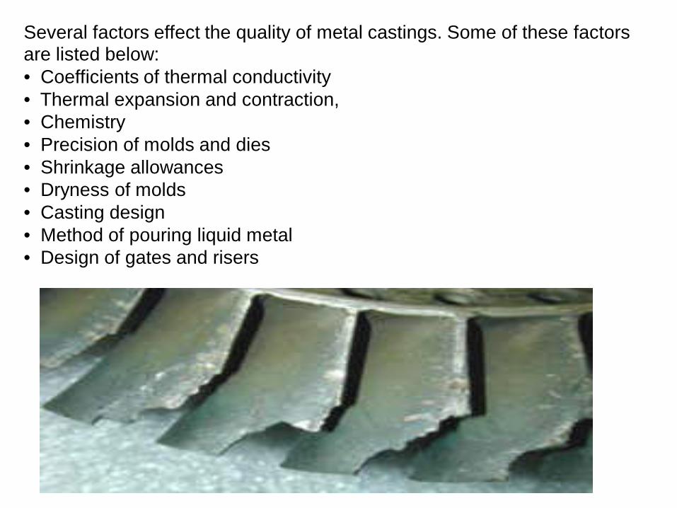
Several factors effect the quality of metal castings. Some of these factors are listed below: • Coefficients of thermal conductivity • Thermal expansion and contraction, • Chemistry • Precision of molds and dies • Shrinkage allowances • Dryness of molds • Casting design • Method of pouring liquid metal • Design of gates and risers

Casting Discontinuities Some common casting deficiencies are: • Inclusions • Porosity (blow holes, pinholes) • Cold Cracking • Hot Cracking • Cold Shuts • Surface irregularities • Distortion • Improper composition

Casting Failure Analysis Casting failures can be due to various causes. Improper loading or environment may contribute to the cause of failure. Casting imperfections may or may not contribute to the cause of failure. Some imperfections may be commonly occurring discontinuities or anomalies that are normally expected to be present in castings. Other imperfections are casting defects that result in failure of the casting. Failure analysis can determine the cause of the casting failure and determine if a casting imperfections was the primary or contributing cause of failure.

Casting Concerns Casting issues AMC can evaluate for your organization are listed below:
Mold designs Mold types Sand casting Investment Casting Ceramic mold casting Plaster mold casting Shell mold casting Permanent Mold Casting Gating systems Cores Solidification of metals Cast structures Fluidity of molten metals Heat transfer Shrinkage Casting defects
Die casting types Centrifugal casting Turbine blade casting Heat Treatment Ferrous alloys Non-ferrous alloys Heat treatment processes Cleaning/finishing methods Inspection Testing Casting quality assurance Process Capability Allowance and tolerance Process capability Process variation Cast alloys

Fastener Failure •The primary function of a fastener is to transfer load. There are many types of fasteners. Examples of some requirements for fasteners are listed below: Higher strength • Increased high temperature dependability • Increased low temperature dependability • Reduced cost • Easier maintenance • Improved corrosion resistance
The choice of a fastener is dependent on the design requirements and environment in which the fastener will be used. Attention to various aspects of the fastener must be considered. Some of these are listed below: • Function of the fastener • Operating environment of the fastener • Type of loading on the fastener in service • Thickness of materials to be joined • Type of materials to be joined • Configuration of the joint to be fastened
Mechanical Fasteners Mechanical fasteners are frequently grouped as listed below: • Pin fasteners • Threaded fasteners • Rivets • Blind fasteners • Special purpose fasteners • Fasteners for composites
Rivets, pin fasteners, and special-purpose fasteners are usually designed for permanent or semipermanent installation. Pin fasteners are fasteners are used in joints in which the load is primarily shear. Pins can be either solid or tubular. A collar is sometimes swaged or formed on the pin to secure the joint. Threaded fasteners are commonly thought of as any threaded part that, after joint assembly, may be removed without damage to the fastener or to the members being joined. Rivets are permanent one piece fasteners one end of the rivet is mechanically upset during installation.
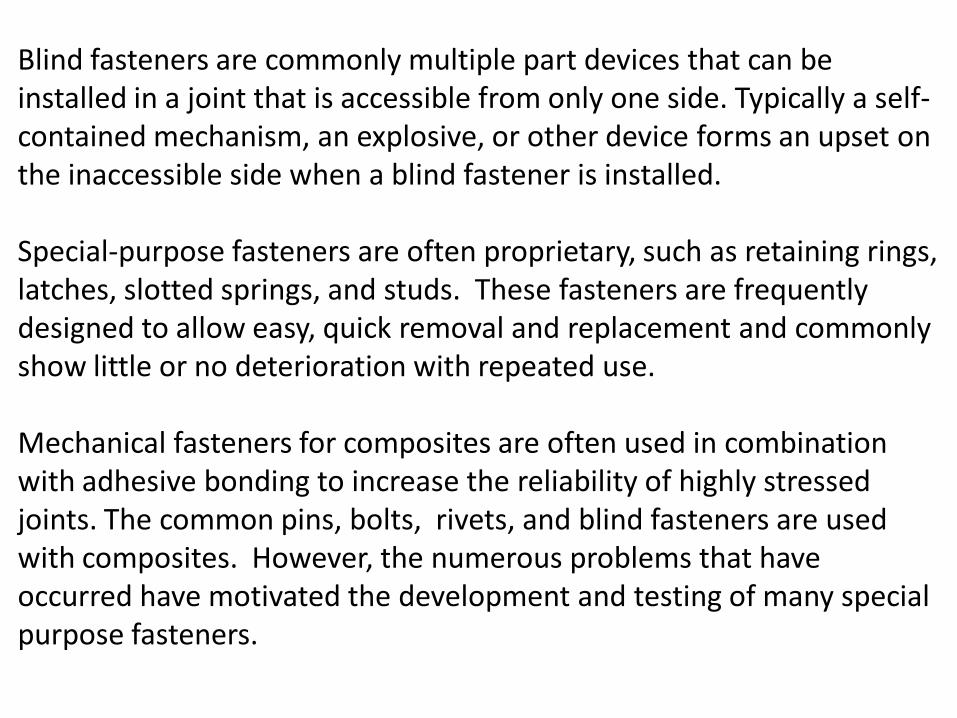
Blind fasteners are commonly multiple part devices that can be installed in a joint that is accessible from only one side. Typically a self-contained mechanism, an explosive, or other device forms an upset on the inaccessible side when a blind fastener is installed. Special-purpose fasteners are often proprietary, such as retaining rings, latches, slotted springs, and studs. These fasteners are frequently designed to allow easy, quick removal and replacement and commonly show little or no deterioration with repeated use. Mechanical fasteners for composites are often used in combination with adhesive bonding to increase the reliability of highly stressed joints. The common pins, bolts, rivets, and blind fasteners are used with composites. However, the numerous problems that have occurred have motivated the development and testing of many special purpose fasteners.

•Pullout of the fastener under load • Drilling damage to the composite • Installation damage to the composite • Delamination of the composite material near the hole • Differences in expansion coefficients between the composite and the fastener • Galvanic corrosion between the composite and the fastener • Fuel leaks around the fastener • Fretting
Some of the problems with fasteners for composites are listed below:
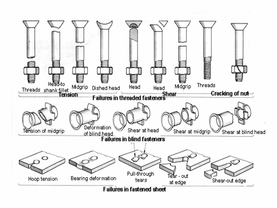

Failure Origins Frequent locations for fastener failure listed below: • In the head-to-shank fillet • Through the first thread inside the nut • The transition from the thread to the shank

Causes of Fastener Failures Some causes of fastener failure are listed below:
• Shear • Overload • Fatigue • Corrosion • Manufacturing discrepancies • Improper installation

Fastener Failure Analysis A fastener may experience either static loading or fatigue loading. Static loading may be tension, shear, bending, or torsion. These static loading conditions may occur in combination. One example of fatigue loading is vibration. In addition to overload and fatigue, some other common reasons for fastener failures include environmental issues, manufacturing discrepancies, and improper use or incorrect installation.
Fastener Failure Analysis A fastener may experience either static loading or fatigue loading. Static loading may be tension, shear, bending, or torsion. These static loading conditions may occur in combination. One example of fatigue loading is vibration. In addition to overload and fatigue, some other common reasons for fastener failures include environmental issues, manufacturing discrepancies, and improper use or incorrect installation.

Some common questions concerning fasteners are listed below: • How were the fasteners torqued? • In what order were fasteners tightened? • What is the best way to verify the torque on fasteners? • How does torque value vary over time?

Fatigue is one of the most common failure modes for threaded fasteners. Fretting failures may result from small movements between adjacent surfaces. Additionally, atmospheric corrosion, liquid immersion corrosion, galvanic corrosion, crevice corrosion, stress corrosion cracking, and hydrogen damage may contribute to fastener failure Material selection, heat treatment, cutting or rolling threads, manufacturing, assembly, and design are some of the factors that effect fastener failures. Failure analysis can determine the cause of the fastener failure and determine the primary or contributing causes of fastener failure.

Roller and Ball Bearings
Roller and ball bearings are commonly used in various components. The rollers or balls are placed in between two raceways. This allows relative motion by rotation of these pieces.
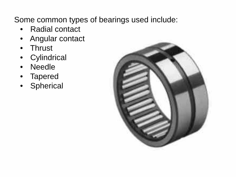
Some common types of bearings used include: • Radial contact • Angular contact • Thrust • Cylindrical • Needle • Tapered • Spherical

Bearing load ratings are established on the results of laboratory rolling contact fatigue tests. Real world conditions such as misalignment, vibration, shock loading, insufficient or inefficient lubrication, extremes of temperature, or contamination, will decrease the life expectancy of the bearings. If these conditions are severe, they may lead to premature failure of the bearings.
Some common characteristics of bearing failures are listed below: • Wear • Fretting • Corrosion • Indentations • Electrical pitting • Smearing • Cracking • Flaking Some of the factors that may lead to bearing failure are improper lubrication, impact loading, vibration, excess temperature, contamination, excessive loading, and misalignment

Gear Failures Gears can fail in several different ways. Increased vibration and noise level from the equipment is commonly associated with gear failures. Cast irons, nonferrous alloys, powdered-metals, and steels are materials used in gears.
•Worm gears • Herringbone gears • Helical gears • Spur gears • Bevel gears • Internal gears

Gear Failure Analysis Some of the failure modes in gears are listed below: • Fatigue • Wear • Stress Rupture • Impact Tooth bending fatigue, contact fatigue, and thermal fatigue are among some of the types of fatigue failures in gears. Abrasive wear and adhesive wear are the common modes of wear failure of gears. Material, manufacturing, engineering, service environment, and heat treatment are some of the causes of gear failures.
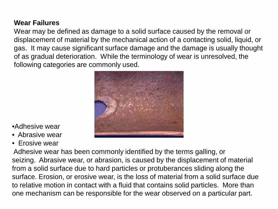
Wear Failures Wear may be defined as damage to a solid surface caused by the removal or displacement of material by the mechanical action of a contacting solid, liquid, or gas. It may cause significant surface damage and the damage is usually thought of as gradual deterioration. While the terminology of wear is unresolved, the following categories are commonly used.
•Adhesive wear • Abrasive wear • Erosive wear Adhesive wear has been commonly identified by the terms galling, or seizing. Abrasive wear, or abrasion, is caused by the displacement of material from a solid surface due to hard particles or protuberances sliding along the surface. Erosion, or erosive wear, is the loss of material from a solid surface due to relative motion in contact with a fluid that contains solid particles. More than one mechanism can be responsible for the wear observed on a particular part.