FATIGUE CRACK PROPAGATION FRACTURE ... (Fig 6c), crack growths in the fusion zones vere slower than...
22
NN CIO Technical '%eport 85066 '1 July 1985 FATIGUE CRACK PROPAGATION AND FRACTURE TOUGHNESS OF- PLASMA ARC WELD-ED "Ti-6A1-4V ALLOY by T. -S.. Baker -71 _qo'-uwent Exettitive, Ministry-ocf Defence
Transcript of FATIGUE CRACK PROPAGATION FRACTURE ... (Fig 6c), crack growths in the fusion zones vere slower than...
NN
CIO Technical '%eport 85066
'1 July 1985
FATIGUE CRACK PROPAGATION ANDFRACTURE TOUGHNESS OF- PLASMA ARC
WELD-ED "Ti-6A1-4V ALLOY
by
T. -S.. Baker -71
_qo'-uwent Exettitive, Ministry-ocf Defence

UDC 669.295.5.71.292 : 621.791.755 539.42 620.172.24539.219.2 : 539.431 539.211
SROYAL AIRCRAFT ESTABLISHMENT
Technical Report 85066
Received for printing 16 July 1985
FATIGUE CRACK PROPAGATION AND FRACTUVX TOUGHNESS OF
PLASMA ARC WELDED Ti-6A1-4V ALLOY
by
T. S. Baker
SUMMARY
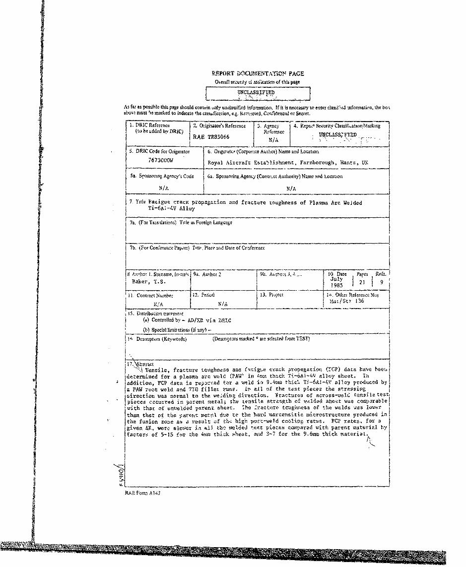
Tensile, fracture toughness and fatigue crack ;ropagation (FCP) datahave been determined for a plasma arc weld (PAW) in 4mv thipk Ti-6Al-4Valloy sheet. In addition, FCP data is reported for a weld in 9.6mm thickTi-6A1-4V alloy produced by a PAW root weld and TIG filler runs. In all
of the test pieces the stressing direction was normal to the weldingdirection. Fractures of across-weld test pieces occurred in parent metal,
the tensile strength of welded sheet was comparable with that of unweldedparent sheet. The fracture toughness of the welds was also lower than
that of the parent metal due to the hard martensitic microstructure pro-duced in the fusion zone as a result of the high post-weld cooling rates.
FCP rates, for a given AK, were slower in all the welded test pieces com-pared with parent material by factors of 5-15 for the 4mm thick sheet, and3-7 for the 9.6mm thick material.
Departmental Reference: Materials/Structures 136I Acoession For
NTIS GP.A&I
DTIC TAB 0Copyright Unanmounced []
S' Ju;tificationController HMSO LondonS12885
Distribution!
/ DYIC A.% !1½bility ^,,desCop Avail 8-dlhjr
SLJpc__i
LIST OF CQMTEITS
Page
I IDIMODUCTION 3
2 EVPRONTAL TECHNIQUES 3
2.1 Material 3
2.2 Mechanical tests 3
3 RESULTS 4
3.1 Tcnsile tests 4
3.2 Fracture toughness 4
3.3 Fatigie cra'.k propagation 4
4 DISCUSSION 5
5 CONCLUSIONS 5
Tables I Lo 5 7
References 12
Illustrations Figuxes 1-7
Report documentation page inside back cover
t

:3
II INTRDUCTION
This Report describes the results of an evaluation of a Aes thick plasma arc weldedTi-6A1-4V alloy sheet supplied by Westland Helicopter* Limited (WHL). Tensile, fractureItoughness and fatigue crack propagation (FC') data were obtained for the sheet, which was
from the same batch as that used in a larger concurrent evaluation of laser bemm welded
sheet -3. In addition, FCI data is reported for -;-rau metal and welded 9.6=m thicksheet (plasma arc + TIC- filler). These tests at RAE formed part of the support for the
welding programme at WHL4
2 EXPERIMENTAL TECHNIQUES
2.1 Material
The 4m, thick Ti-6A1-4V alloy sheet was supplied to WHL by the American Metals
Service Export Corporation, to MIL-T-9046 type 3, composition C. Two half panels
-,150 x 450 am were degreased in MEg (Methylethylketone) prior to being butt welded byM in a single pass using the autogeneous pulsed plasma arc process (see Table I for
details of welding parameters) to give a panel 1-300 x 450 mm ('4th trial' sheet, WHLreference). Test results for parent metal are taken from the laser welded sheet
1-3 4prograine . Welding parameter details for the 9.6n thick material are included ;n
Table •.
No micropLrosity was detected by radiography and although the weld was undercut
along its length, a macrosection through the weld (Fig la) showed that the depth of
undercutting was very small. Large grains were visible at the centre of the fusion zonewith much smaller grains in the heat affected zone (HAZ). The width of the fusion zone. HAZ was 13.0 = at the top surface and 13.8 mm at the bottom surface of the weld. The
microstruct, -e of the fusion zone consisted of martensitic a within the former $
grains (Fig 1b). The large fusion and heat affected zones were caused by the sloi
(0.08 m/man) welding speed.
2.2 Mechanical tests
Tensile, iracture toughness (Kc) and FCP tests were carried out in laboratory airat room temperature on test pieces which were cut from the 4,m thick welded sheet in the
LT orientation Undercuts were removed by machining equal amounts of metal from both
top ewd bottom surfaces, giving a final thickness of %.3.7 ra. FCP test pieces from
9.6mm plate were machined to %8 am. The location of each 4mm thick test piece in thewelded sheet is shown in Fig 2. The parent metal test pieces were cut frot other sheets
as described elsewhere
Tensile tests were carried out on 'B' size metric test pieces according to BS4.A4.
Since the sheet was too thin for valid K c values to be determined, K testsIc c
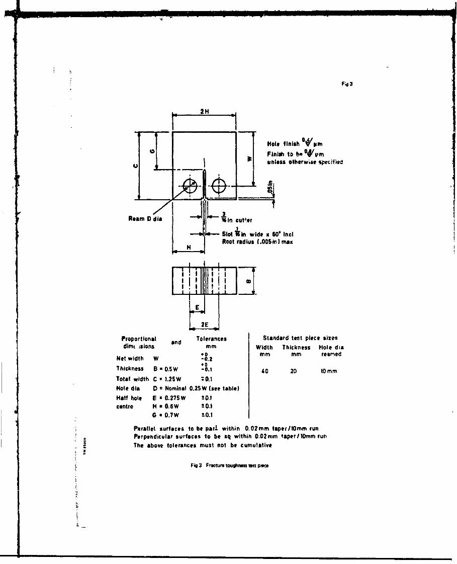
were carried out according to ASTM E561-81 on compact tension test pieces (Fig 3).
* First letter denotes direction normal to crack plane. Second letter denotes crack;rowth direction.

4
Compliance curves had been determined earlier 1 , 2 using parent metal test pieces toconfirm that the crack opening displacement (CCD) aeasurements gave accurate values of
crack length.
The PCP tests were carried out using a SE% 3-point bend test piece (Fig 4); side-
plates were bolted to both sides at each end of the 4am thick test piece to preventtwisting. Tests were carried out in a 2 ton Azler Vibraphore machine fitted with asolid state Howden HFP-S8 controller, with the strers ratio R - 0.1 . The crack length,'a', was measured in all but one of the tests using a dc electric potential m-..nod 1 . 6
and was e_,Lked optically with a travelling microscope. Test piece No.PLME was testedusing a recently developed automatic technique 7, in which a microcomputer is used tocontinuously monitor two dc potentials, and from their ratio, determine instantaneous
values of crack length, growth rate and stress intensity range. Details of the 4am thick
test pieces cut from the welded sheet, together with other test pieces supplied by WHL
and cut from separate sheets are given in Table 2.
3 RESLLTS
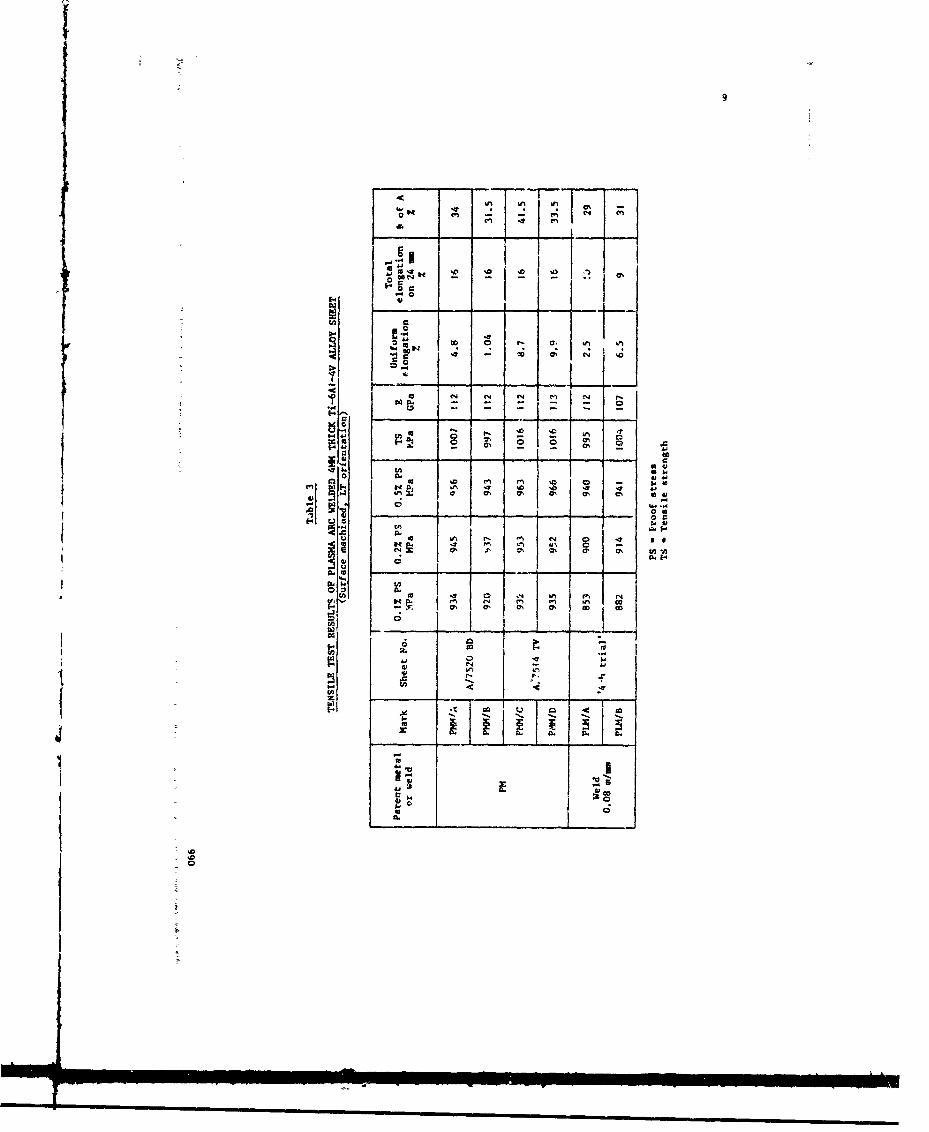
3.1 Tensile tests
The results of the tensile tests are shown in Table 3. The acrzos-weld test pieces
fractured in the parent metal away from the weld at stresses slightly lower (by 7%(0.12 PS), 4% (0.21 PS), 1.7% (O0.5 PS and TS)) than those for the parent metal, ductilityvalues, esoecially elongation, were also lower. These strength and ductility values are
typical of across-weld test pieces, and are caused by slight annealing of the parent
metal, and reduced ductility in the haider fusion zone,
3.2 Fracture toughness
The results of the fracture toughness (Kc) tests are shown in Table 4. The two Kc
values obtained for the parent metal, and one for the fusion zone of a welded test piece,
did not satisfy the valiulty criteria, In one of the parent metal test pieces (PQW1.)
the crack deviated by 090° from the normal crack growth direction (Fig 5a) due topreferred orientation in the sheetI. In the welded test pieces crack growth remained inthe fusion zones throughout the duration of the tests (Fig 5b), The valid K value of
c
108.1 MPa/m obtained for fusion zone material (PUILI, Table 4) is ach higher than values1,2 8obtained for faster cooled laser beam fusion zones '2. Banas obtained values of 63.3,
66.? and 73.4 IParm in plasma welded 6.4am thick Ti-6AI-4V alloy*. The higher value
obtained in this work was probably due to the slow welding speed used, which resulted in
a coarse grain size and tough fusion zone.
3ý3 Fatigue crack propagation
Fatigue crack growth curves for the 4am thick parent metal (Fig 6a) and plasmawelded sheet test pieces (Fig 6b) showed good agreement between test piece pairs (A & B)
cut from the same sheets.
SFracture toughness values in Ref 8 had incorrect units; corrected values are given here.
5
Growth rates in test piece PILC, cut from a different sheet and supplied by WHl., were
faster for a given AK . than those for the sheet in Fig 2 (tesi pieces PUIMA and PLMLB),as shown in Fig 6b. Mean fatigue crack growth rates are plotted in Fig 6c. For a given
&V growth rates were always significantly slomer in plasma welied fusion zones compared
to the parent metal, especially at low AK values (Table 5); for mean AK values of 20
and 2! HParm (Fig 6c), crack growths in the fusion zones vere slower than in the parent
metal by factors of 15.6 and 5.2, respectively.
Fatigue crack growth curves for t3~e 9.6rai thick material are shown in Fig 7,~ The
curve for the parent metal test piece was similar to the corresponding curve for the
l4m thick wterin (Fig 6c). Fatigue crack growth rates in the fusion zones were
slower than in the parent metal by faLtors of 3.4 and 6.6, at AK values of 15 and
20 3PaYS, respectively. Grovth rates in the fusion zones were the same as those
determined for the 4m thick test piece PIMLC (Fig 6b) and for 4me thick sheet which had
been lastr beam welded ar 5 k-_ a, In
4 DISCUSSION
The plasma arc weld examined in this Report is probably not typical oa 1!AW titanium
alloy sheet; thiis is becaure the welding equipment, a Thermal Arc WC122A Welding Console,4was being used at its w.immur capacity . This necessitcted the use of a slow traverse
speed resulting in a relatively wide and slowly cooled weld. A higher capacity machine
would have been operated at a faster welding speed, resulting in higher cooling rates
and therefore different microstructures and mechanical properties. However, the welds
produced were pore-free with minimal undercutting and satisfactory mechanical properties,
A faster postueld cooling rate would probably result in lower fracture toughness, and a
stress relief heat treatment for 4.5 h @ 6250
C could reduce the FCP resistance to that of
the parent material, based upon preliminary results obtained on laser beam welded sheet9
If welded sheet was to be used without removal of undercuts then S/N data would be
required, The fatigue strength (S/N) of the PAW sheet used in the current work was
reported to be approximately half that of the parent metal sheet 4; the cracks initiated
at notches present in the top surface 'ripple' at the edge of the fusion zone. In work
carried out on laser bean wel.s it was shown thot the presence of undercuts (up to
j 0.2 me deep) significantly reduced the fatigue strength of the sheet3-3
S5 CONCLUSIOIS
(1) Across-weld test piece from a 4mm thick Ti-6AI-4V alloy plasma are welded joint
failed in the parent metal and the tensile strength was comparable with that of parent
metal; ductility values of welded sheet were lover however by 40% (elongation) and 15%
(reduction of area).
(2) Fracture toughness vaiues were difficult to mnasure accurately; the only valid Kcvalue obtained was 108.1 MParm for 4me thick plasma welded surface machined sheet.

(3) Fatigue crack growth rates in the fusion zones of weldet3 4=a and 9.bun thick
material were slower, for a given stress intensity '>20 Wfav, by factors in tle range
3.4 to 6.6 compared to the parent metal; the factor vas t15 at srets intensities
20 NPar/ in the 4um thick welded sheet.
S:i iii ll i': i il
• ruuuui• • • in C

7
Table I
PLASM "tC WELDING PA 4
Sheet thickness Us 4 9.6
Pass number 2 2 jJ
Weld type Pulsed plasma TIC filler
Weld current A 100 110 205 205
Top pulsi time 6 0.4 0.6 - -
BacKground current A 10 10 - -
Low:r pulse time s 0.2 0.2 - -
Slope up A/s 20 20 so 50
A/a 10 10 20 20Sequence terminste - - - 2
A 8 8 10 10
Carriage speed m/min 0.08 0.04 0.13 0.13
Shielding gas flow rate I/min t0 10 10 10
ilasma flow rate 1/min 1.5 1 1.5 - -
Trailing shield flow rate L/min 14 14 14 14
Backing gas flow rate /min 14 14 14 14
Arc voltage V - - 1 11
Wire feed m/min - - 1.95 1.95
Up slope a - - 2,0 2.0
Down slope a - - 0.5 0.5
Oscillating speed -- 80 70
Traverse distance am - - I 2
.0
0 r

Table 2
DATA FOR FATIGUE CRACK PROPAGAIION TEST PIECES(Surface machined, LI orientation, R ".1)
Thickness, mmParent metal Markt
or weldIn'.tial Machined
PMKLA* 3.74
PMP•.B 3.73
PLM1A 4 3.50
Weld
0.08 m/min
PLMLCe 3.31
PM PMMLI 8.37
9.6
Weld* P~.LE 7.7:
* PAW root - TIG fillers
t PM - Parent metalM - Machined surfaceL or T - direction normal to crack planeIL - Plasma welded
e Test pieces supplied separately by WestlardHelicopters Limited
A Tested using automatic computer controlledtechnique7
I
C4I cm m -
a.7
¾as'0 m 0
~~~ 0 9. .
I -7 -J 0% 0% e' I '
1- an N___ -.z- -L
&J%Ii __v
q.'
En i N ~ ~ p
44 NP '~ J~ U% to
41a % 0 ~ % UJ
i-~ 0 .

10
0
0
0040
co -- 4 0
c. 01 t:
CL-4
>1 N N
Kt
En m 4C .r= i l
aj -
- acc 2 w.
W- 4 -to I-
4C
0 0 s ' uN N . - 10 0 0E
cc ~ I-C6 kV .

4 4
444 -7IT 001 0x I o x
000 0.r- 01
c NN c-
ý4
0III I II
U 000 O~cc.0
~~t :9XX XX
CN0 14
12
REFERESCES
NO. Author Title, etc
I T.S. Iaker Evajuation of laser beca welded rn thick Ti-6AI-4V alloy sheet
RAE Technical Report 85065 (1985)
2 T.S. Baker Mechanical propertieg of laser welded 4mm thick Ti-6A1-4V alloy
P.C. Partridge sheet
Proc.Sth Int.Conf. on Ti~aniim, Murich. 2, 815,
10-14 Sept. 1984
4 T.S. Baker F-iigue properties of km thick laser welded Ti-•AI-4V sheet
P.G. Partridge Proc.2nd Int.Conf. on Fatigue & Fatigue Thresholds, Birmingham,
3, 1763, 3-7 Sept 1984
4 J.E, Penn Evaluation of improved welding techniques
A. Davies Wentlond Helicopters Ltd. NOD Contract No.ASIA/435
5 ASTM Standard practice for R-curve determinstion
*•5T E561-81
6 D.M. C ibey Measurement of the length of a central or edge crack in a sheet
S. Pearson of metal by an electrical resistance metbod
RAE Technical Report 66402 (1966)
7 C.M. Ward-Close A computer-baseJ crack measurement and control system
RAE Technical Memorandum HAT 389 (1982)
8 C.M. Banas Electron beam, laser beam and plasma arc welding studier
NIASA Contractor Report No.NASA CR-132386 March 1975
9 T.S. Baker RAE work - to be published

Fig I
-4'j
~~tz-
Fig I Suction through pluwra arc weld in 4mm ihidi T1SAI4V~ shee3 ~(a) macrostructure, (b) microgtrum-rje in fusion zone
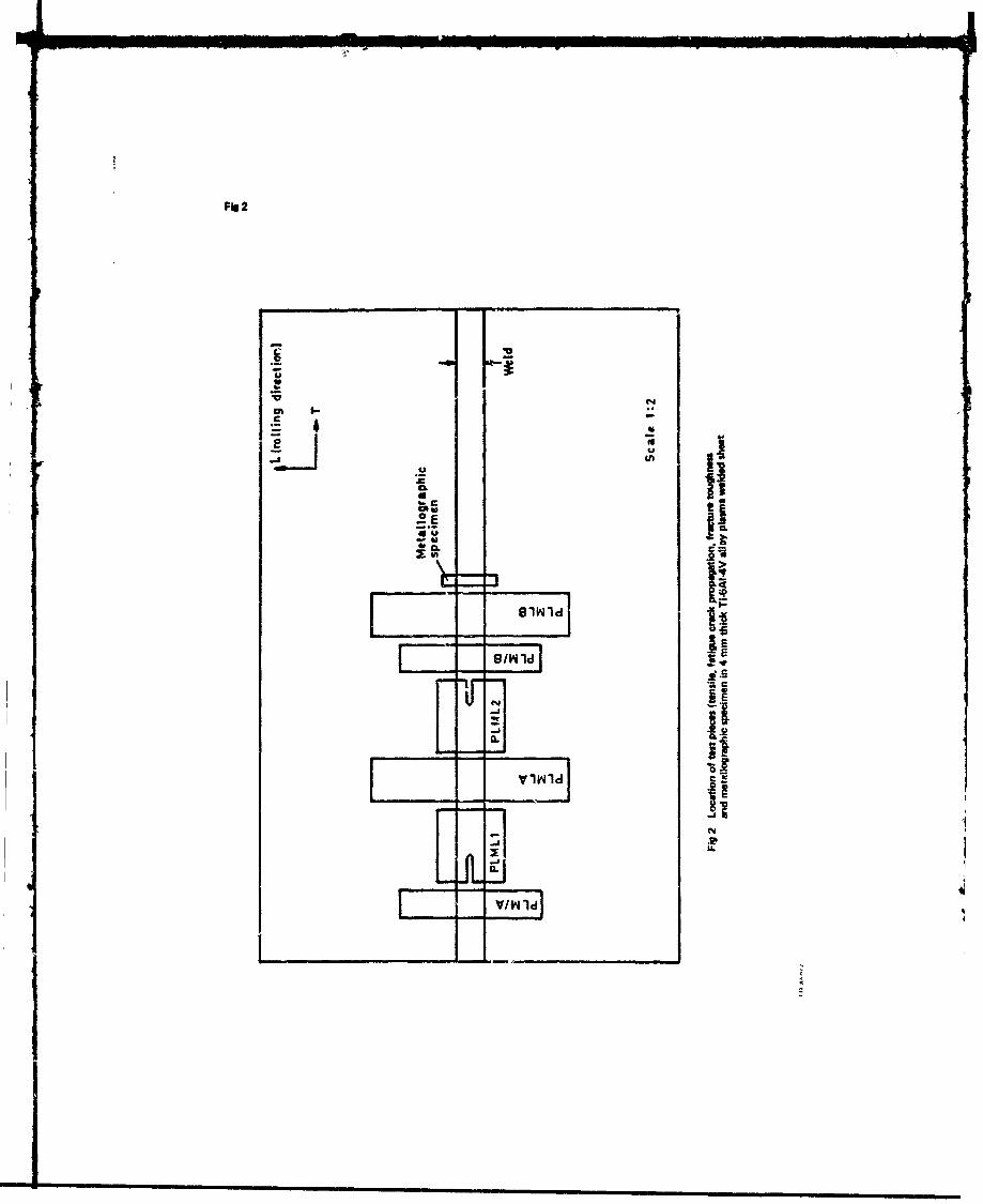
Fig 2
LiLEuE-UE
* a. K
V/W Id
S~F•I 3
2H _
-a 2Hole finish OVIamFinishl to b4"vtm
) unless otherwise "ecified
Ream D din -16 in cuter
Slot *in wide x 60' inctRoot radius (.OOSn) max
2E
Proportional and Tolerances Standard test piece sizesdimt isions mm Width Thickness Hole dia
*N0 mm mm reaMedNot width W -0*2" 0Thickness 0 O.SW -0.1 40 20 10mm
Total width C 1.25W 0.1
Note dia D 0 Nominal 0.25W (see table)
Half hole E z 0.275W 20.1centre H : 0.6W 1-0.1
G 0.7W -0.1
Parallel surfaces to be parn within 0.02mm taper/t0mm runPerpendicular surfaces to be sq within 0.02mm taperllOmm runThe above tolerances must not be cumulative
Fig 3 Fre-ture toughness test pece

Fie 4
s so
""- .10
142
15
Holes - 3mm clearance
All dimensions in mm
Fi 4 F•aIlu era* plopgtion ItM piefsa. LT b. TL orintation
-I

Fig SA~b
PARENT METAL 5 mmI
Fig Sa Frwwctu tughness(Ks) ustplacefracturs, (a) PMMLI, Ib) PMML2
.9A.
- !0
b~~ a f'i
PLASMA WELDED5m
Fig 5b Fracurtoughness(Ks) testpiacfrac'jres(aPIMLI. (b) PLML2

Fig Go
I0-3
o PMMLA
a PMMLB
R 0.1
LT orientation
E
z0
00
mA
U
U.
10"- A l' 191 41.. 1J_ A , • *• I * i ll A I I I A*
5 6 7 8 9 10 20 30 4.0 50 60Stress intensity factor range AK (MPar/')
Fig 6a Fgt"lU crack growth turns foPmm Wantl -. urfam machmod4 mn thick AMe
EI I I I I I Il| I I I I I I l l

Fig ob
@ PLMLA
* PLML B
A PLMLC
R 0.1 0aLT orientation
A
- 10"EE
z
2 a
._ I.
10 *_ * | i .3.1.1 *ii ,. *i * .1 * * * i
5 6 7 8 9 10 20 30 40 SO 60Stress intensity factoi range 6K ,MPajm-
Fig 6b Fatigue crack pgowth wives for plam wm le sui rfmachWed 4 mm thick --%wt
S • .I _ . . -

S~Fig 7
PMMLI (parent motal)j i 0 LMLE 'welded)
R:0.1
LT orientation
0 0U 0z
U
L
5 67/8 9 10 20 £0 /,0 50 60
Stress intensity facto., range 6K (MPa4"1i)
SFig 7 Fatigue craci growth curves for welded (PAW mnd TIG filler) sid
39Iu
S paent rmeta surface machined 9.6 mm thick plat
~~~E .. . . .: • •• • ,• ,• = : -,• •• '•• • ' l •
RRMPOT XICUM-NTATi-014 PAGE
Qierall stecunty di ssikcatian of this pageUJNCLASSIFIED
As far as possible this page should contaiin ý;tly undlaksifiedi iforniation. If i is ritcessary to enter scitae- informnation, the boxj abev- must 'it mnarked to indicate the cia Awcasion, c.t, X-ntcted' cck-i"IdentWnz o Secret.
D.IRIC Reference 2. Qtigi-tor's Refejence Aec .Rp: ~crt lstlto/akn
(to bee idddbyDi ) RAE TR850E66 I RfrneUrI~SID -5. DRIC Codce for Originator 6. Origivaicý (Corpormse Autho-) Name and Locatio-i
767~CUWRoy t Aicraft Es~tal).Iishmerst, Farnborough, Hlants, UK_
Sa. Sj~'nsoring Agency's Code 6a. Sponsoring Agenrny (Contr,--ct Authority) Name and Locstior.
N/A N/A
7- Title Fatigue crack proap.garioin and 'fracture toughness of Plasma Arc Welded
f7a. :cr~-rkLain1 Til ForeiginLanguas7
fb, (FrCofruc pzrs Trit i. Ph-ce Lind Date of Conf erencE
is Aw~hc- 1. Surnamei, in .. ab; 9a. Author 2 19b. Auv.c.'-.s 3t *. MO Nite Pal' Refs.'Baier, T.S. 1 21 It 9
1, Contract Ni,-sib,(r 0. Nfi?.Pod I13. Pio;cct 14i. OhrRfrn~Nmatiatr/ 136",/ I. ----------__ _ _
t1:1. D'istributionl taterment
Descriptors (ewif nee t eetiffor 1ET
Tensile, fracture -oughness ana fttzigte crack provagaticin -(YCP) data Iiave beet,4dt for a plasma arc Wetld (PAW' in 4.tht& Ti-6Ai-4-V allo
!addition, -.C12 data ia rpzvztd tor a vtld iat 9A;ýnv thiol- Ti-6Ai--4V alloy produced byl
a PAW root weld adTIC-fle rns valo the test pi ecez the si~raessixgIarcinwsnra otevliz ieton rc-rs fars-et esl etIpee curdi.-aetmtl h esl tzgho eddAetwscmaal
"'Ik
AAE- Fort Ai 43

![FATIGUE CRACK INITIATION AND PROPAGATION IN … Library/101. Fatigue Crack... · 3 or predict fatigue life [15, 20]. In this paper we have conducted a detailed examination of fatigue](https://static.fdocuments.in/doc/165x107/5ab7a8aa7f8b9ad5338bd8f5/fatigue-crack-initiation-and-propagation-in-library101-fatigue-crack3-or.jpg)