Fatigue and Corrosion Fatigue Properties of Alloys 625 ... · specimens was a machined,...
14
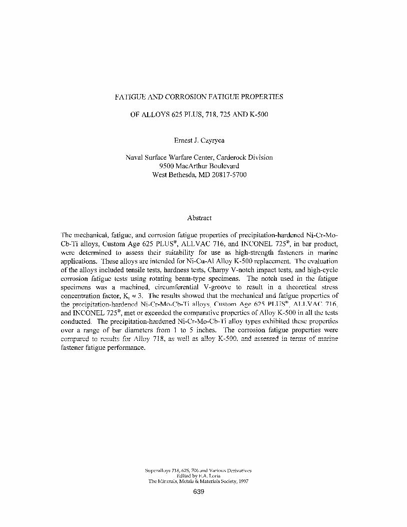
FATIGUE AND CORROSION FATIGUE PROPERTIES OF ALLOYS 625 PLUS, 718,725 AND K-500 Ernest J. Czyryca Naval Surface Warfare Center, Carderock Division 9500 MacArthur Boulevard West Bethesda, MD 20817-5700 Abstract The mechanical, fatigue, and corrosion fatigue properties of precipitation-hardened Ni-Cr-Mo- Cb-Ti alloys, Custom Age 625 PLUS@,ALLVAC 716, and INCONEL 725@, in bar product, were determined to assess their suitability for use as high-strength fasteners in marine applications. These alloys are intended for Ni-Cu-Al Alloy K-500 replacement. The evaluation of the alloys included tensile tests, hardness tests, Charpy V-notch impact tests, and high-cycle corrosion fatigue tests using rotating beam-type specimens. The notch used in the fatigue specimens was a machined, circumferential V-groove to result in a theoretical stress concentration factor, K N 3. The results showed that the mechanical and fatigue properties of the precipitation-hardened Ni-Cr-Mo-Cb-Ti alloys, Custom Age 625 PLUSa, ALLVAC 716, and INCONEL 725@, met or exceeded the comparative properties of Alloy K-500 in all the tests conducted. The precipitation-hardened Ni-Cr-Mo-Cb-Ti alloy types exhibited these properties over a range of bar diameters from 1 to 5 inches. The corrosion fatigue properties were compared to results for Alloy 718, as well as alloy K-500, and assessedin terms of marine fastener fatigue performance. Superalloys 718,625,706 and Various Derivatives Edited by E.A. Loria The Minerals, Metals & Materials Society, 1997 639
Transcript of Fatigue and Corrosion Fatigue Properties of Alloys 625 ... · specimens was a machined,...
FATIGUE AND CORROSION FATIGUE PROPERTIES
OF ALLOYS 625 PLUS, 718,725 AND K-500
Ernest J. Czyryca
Naval Surface Warfare Center, Carderock Division 9500 MacArthur Boulevard
West Bethesda, MD 20817-5700
Abstract
The mechanical, fatigue, and corrosion fatigue properties of precipitation-hardened Ni-Cr-Mo- Cb-Ti alloys, Custom Age 625 PLUS@, ALLVAC 716, and INCONEL 725@, in bar product, were determined to assess their suitability for use as high-strength fasteners in marine applications. These alloys are intended for Ni-Cu-Al Alloy K-500 replacement. The evaluation of the alloys included tensile tests, hardness tests, Charpy V-notch impact tests, and high-cycle corrosion fatigue tests using rotating beam-type specimens. The notch used in the fatigue specimens was a machined, circumferential V-groove to result in a theoretical stress concentration factor, K N 3. The results showed that the mechanical and fatigue properties of the precipitation-hardened Ni-Cr-Mo-Cb-Ti alloys, Custom Age 625 PLUSa, ALLVAC 716, and INCONEL 725@, met or exceeded the comparative properties of Alloy K-500 in all the tests conducted. The precipitation-hardened Ni-Cr-Mo-Cb-Ti alloy types exhibited these properties over a range of bar diameters from 1 to 5 inches. The corrosion fatigue properties were compared to results for Alloy 718, as well as alloy K-500, and assessed in terms of marine fastener fatigue performance.
Superalloys 718,625,706 and Various Derivatives Edited by E.A. Loria
The Minerals, Metals & Materials Society, 1997
639

Introduction
Backpround
High-performance marine equipment, particularly with direct exposure to seawater, have utilized nickel-copper-aluminum alloy K-500 (MONEL@ K-500, UNS NO5500) to QQ-N-286, where high-strength fasteners are required in bolted joints. The alloy has extensive service use, but the limitations of the material are becoming evident in regard to marine exposures where (1) fasteners are required for bolted joints to alloys more noble than Alloy K-500 in seawater and (2) in areas of intense cathodic polarization. Service failures of alloy K-500 bolts have occurred due to intergranular (hydrogen) cracking in cathodically protected equipment [ 1,2]. In corrosion studies conducted of Alloy 625 components bolted together with Alloy K-500 fasteners immersed in seawater, the Alloy K-500 fasteners lost an average of 40% of their original weight in one year due to galvanic corrosion [3]. Alternate high-strength fastener alloys with yield strength of 100 ksi (690 Mpa) or greater for seawater immersion service are required, and high-performance propulsion equipment requires fastener alloys of 150 ksi (1035 Mpa) minimum yield strength.
Candidate alloys for high-strength marine fastener applications included high-strength nickel- base alloys and titanium alloys. Most were developed for high temperature and/or aerospace applications, and data regarding their performance in seawater service is scarce. For fastener applications, data on mechanical properties, fatigue and corrosion fatigue properties, notch sensitivity, galling resistance, machinability, thread-forming operations, in addition to galvanic, crevice, and stress corrosion performance, are required for the evaluation of candidate materials. High-performance bolt alloys with yield strength greater than 690 MPa, high fatigue and corrosion-fatigue strength, good seawater corrosion resistance, availability in diameters from % to 6 inches, and some fastener application experience were surveyed. The precipitation-hardened Ni-Cr-Mo-Cb-Ti alloys and Alloy 718 were selected for evaluation.
Bolt Fatigue
Initial alloy selection criteria for bolts and fasteners in marine applications are strength and corrosion resistance. Since fasteners may experience some level of cyclic loading, the fatigue and corrosion fatigue strength must also be considered. Bolt fatigue failures usually occur in the first or second threads, where stress concentration and load pickup is highest, or in the shank-to-head fillet [4]. Metal-to-metal seals, such as bolt head seating in blade hole recess facing, will not reliably keep out seawater, and even effective sealing arrangements are prone to improper installation. Therefore, a bolt alloy with adequate notched, corrosion fatigue resistance is a prudent selection.
Preload is applied to the bolts to minimize the magnitude of cyclic load passing through the bolts [4]. There is an optimum preload for maximum fatigue strength above which the cyclic bolt load component cannot be further reduced. A high-strength alloy allows a high preload level in a slender bolt for the optimum fastener design against fatigue. However, high-strength alloys can be notch sensitive and special thread-forming operations may be required for optimum performance [4].
640
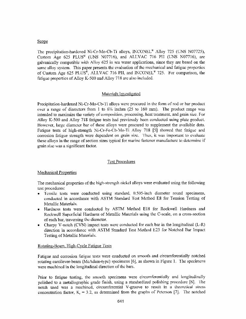
Scope
The precipitation-hardened Ni-Cr-Mo-Cb-Ti alloys, INCONEL@ Alloy 725 (UNS N07725), Custom Age 625 PLUS’ (UNS N07716), and ALLVAC 716 PH (UNS NO771 6), are galvanically compatible with Alloy 625 in sea water applications, since they are based on the same alloy system. This paper presents the evaluation of the mechanical and fatigue properties of Custom Age 625 PLLTS’, ALLVAC 716 PH, and INCONEL@ 725. For comparison, the fatigue properties of Alloy K-500 and Alloy 718 are also included.
Materials Investigated
Precipitation-hardened Ni-Cr-Mo-Cb-Ti alloys were procured in the form of rod or bar product over a range of diameters from 1 to 6% inches (25 to 160 mm). The product range was intended to maximize the variety of composition, processing, heat treatment, and grain size. For Alloy K-500 and Alloy 718 fatigue tests had previously been conducted using plate product. However, large diameter bar of these alloys were procured to supplement the available data. Fatigue tests of high-strength Ni-Cr-Fe-Cb-Mo-Ti Alloy 718 [5] showed that fatigue and corrosion fatigue strength were dependent on grain size. Thus, it was important to evaluate these alloys in the range of section sizes typical for marine fastener manufacture to determine if grain size was a significant factor.
Test Procedures
Mechanical Properties
The mechanical properties of the high-strength nickel alloys were evaluated using the following test procedures: l Tensile tests were conducted using standard, 0.505-inch diameter round specimens,
conducted in accordance with ASTM Standard Test Method E8 for Tension Testing of Metallic Materials.
l Hardness tests were conducted by ASTM Method El8 for Rockwell Hardness and Rockwell Superficial Hardness of Metallic Materials using the C-scale, on a cross-section of each bar, traversing the diameter.
l Charpy V-notch (CVN) impact tests were conducted for each bar in the longitudinal (L-R) direction in accordance with ASTM Standard Test Method E23 for Notched Bar Impact Testing of Metallic Materials.
Rotating-Beam, High-Cvcle Fatigue Tests
Fatigue and corrosion fatigue tests were conducted on smooth and circumferentially notched rotating cantilever-beam (McAdam-type) specimens [6], as shown in Figure 1. The specimens were machined in the longitudinal direction of the bars.
Prior to fatigue testing, the smooth specimens were circumferentially and longitudinally polished to a metallographic grade finish, using a standardized polishing procedure [6]. The notch used was a machined, circumferential V-groove to result in a theoretical stress concentration factor, K = 3.2, as determined from the graphs of Peterson [7]. The notched
641
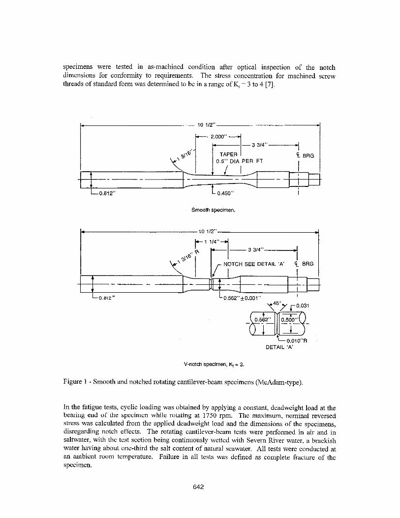
specimens were tested in as-machined condition after optical inspection of the notch dimensions for conformity to requirements. The stress concentration for machined screw threads of standard form was determined to be in a range of K, = 3 to 4 [7].
c
0.5” DIA PER FT
LO.812” L 0.450”
Smooth specimen.
0.562” +O.OOl ”
DETAIL ‘A’
V-notch specimen, Kt = 3.
Figure 1 - Smooth and notched rotating cantilever-beam specimens (McAdam-type).
In the fatigue tests, cyclic loading was obtained by applying a constant, deadweight load at the bearing end of the specimen while rotating at 1750 rpm. The maximum, nominal reversed stress was calculated from the applied deadweight load and the dimensions of the specimens, disregarding notch effects. The rotating cantilever-beam tests were performed in air and in saltwater, with the test section being continuously wetted with Sevem River water, a brackish water having about one-third the salt content of natural seawater. All tests were conducted at an ambient room temperature. Failure in all tests was defined as complete fracture of the specimen.
642
Results and Discussion
Composition and Mechanical Properties
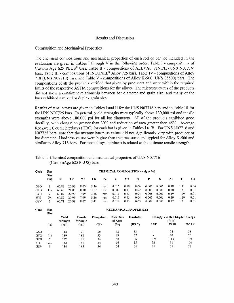
The chemical compositions and mechanical properties of each rod or bar lot included in the evaluation are given in Tables I through V in the following order: Table I - compositions of Custom Age 625 PLUS@ bars, Table II - compositions of ALLVAC 716 PH (UNS N07716) bars, Table III - compositions of INCONELa Alloy 725 bars, Table IV - compositions of Alloy 718 (UNS N07718) b ars, and Table V - compositions of Alloy K-500 (UNS 05500) bars. The compositions of all the products verified that given by producers and were within the required limits of the respective ASTM compositions for the alloys. The microstructures of the products did not show a consistent relationship between bar diameter and grain size, and many of the bars exhibited a mixed or duplex grain size.
Results of tensile tests are given in Tables I and II for the UIW NO7716 bars and in Table III for the UNS NO7725 bars. In general, yield strengths were typically above 130,000 psi and tensile strengths were above 180,000 psi for all bar diameters. All of the products exhibited good ductility, with elongation greater than 30% and reduction of area greater than 45%. Average Rockwell C-scale hardness (HRC) for each bar is given in Tables I to V. For UNS NO771 6 and NO7725 bars, note that the average hardness values did not significantly vary with producer or bar diameter. Hardness values were higher than that measured and typical for Alloy K-500 and similar to Alloy 718 bars. For most alloys, hardness is related to the ultimate tensile strength.
Table I. Chemical composition and mechanical properties of UNS NO77 16 (CustomAge 625 PLUS) bars.
Code Bar CHEMICAL COMPOSITION (weight %) Size (9 Ni Cr MO Cb Fe C Mn Si P S Al Ti Co
GSO 1 60.86 20.96 8.00 3.36 rem 0.015 0.09 0.06 0.006 0.001 0.18 1.31 0.04 GTO 1% 60.65 21.05 8.18 3.51 rem 0.009 0.01 0.02 0.003 0.001 0.20 1.31 0.01 GTH 2 60.82 20.99 7.99 3.26 rem 0.011 0.03 0.04 0.005 0.001 0.19 1.29 0,Ol GTI 2% 60.82 20.99 7.99 3.26 rem 0.011 0.03 0.04 0.005 0.001 0.19 1.29 0.01 GSV 3 60.71 20.98 8.07 3.41 rem 0.014 0.03 0.05 0.008 0.001 0.22 1.31 0.01
Code Bar MECHANICAL PROPERTIES Size
Yield Tensile Elongation Reduction Hardness Charpy V-notch Impact Energy Strength Strength of Area (ft-lb)
(4 (ksi) (ksi) (“A) W-1 WW OoF 75 oF 200 oF
GSO 1 144 191 30 48 33 54 56 GTO 1% 139 188 33 49 37 60 70 GTH 2 132 181 34 58 36 109 113 109 GTI 2% 132 181 34 56 35 92 91 100 GSV 3 134 185 34 54 34 15 15 78
643
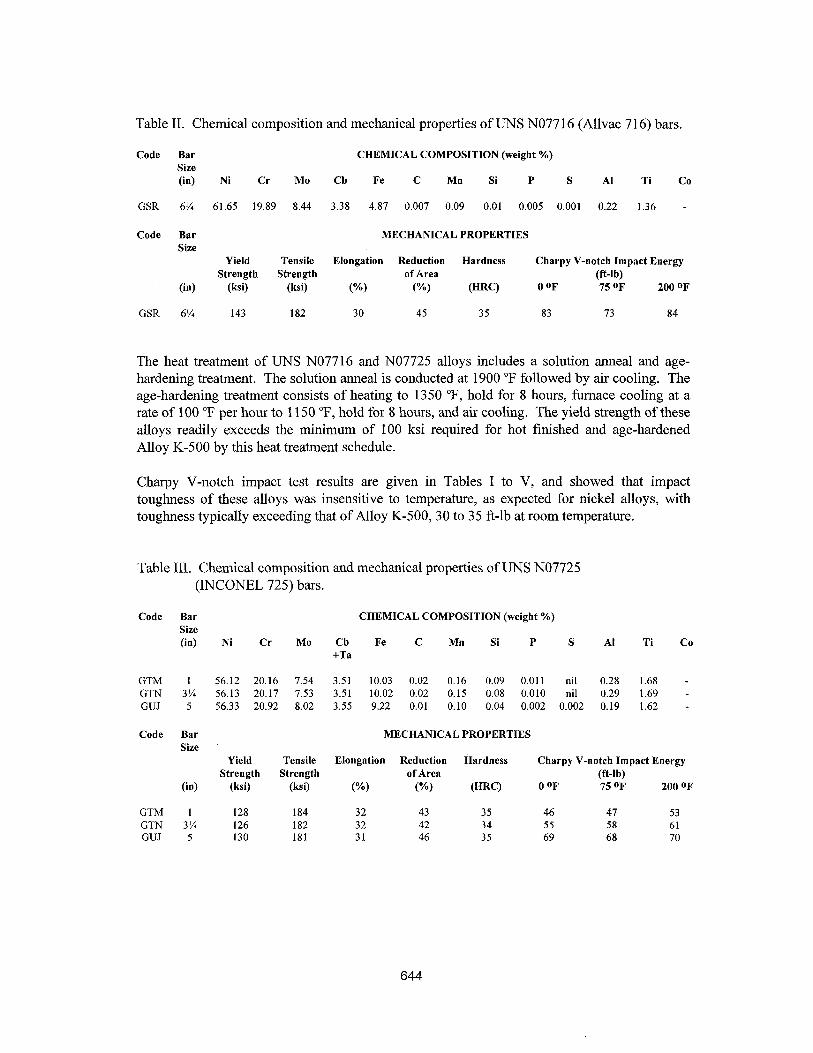
Table II. Chemical composition and mechanical properties of UNS NO7716 (Allvac 716) bars.
Code Bar CHEMICAL COMPOSITION (weight %) Size 64 Ni Cr MO Ch Fe C Mn Si P S Al Ti Co
GSR 6% 61.65 19.89 8.44 3.38 4.87 0.007 0.09 0.01 0.005 0.001 0.22 1.36 -
Code Bar MECHANICAL PROPERTIES Size
Yield Tensile Elongation Reduction Hardness Charpy V-notch Impact Energy Strength Strength of Area (ft-lb)
64 (ksi) (ksi) WI (“A) (Hw OoF 75 oF 200 oF
GSR 6% 143 182 30 45 35 83 73 84
The heat treatment of UNS NO7716 and NO7725 alloys includes a solution anneal and age- hardening treatment. The solution anneal is conducted at 1900 “F followed by air cooling. The age-hardening treatment consists of heating to 1350 “F, hold for 8 hours, furnace cooling at a rate of 100 “F per hour to 1150 “F, hold for 8 hours, and air cooling. The yield strength of these alloys readily exceeds the minimum of 100 ksi required for hot finished and age-hardened Alloy K-500 by this heat treatment schedule.
Charpy V-notch impact test results are given in Tables I to V, and showed that impact toughness of these alloys was insensitive to temperature, as expected for nickel alloys, with toughness typically exceeding that of Alloy K-500, 30 to 35 ft-lb at room temperature.
Table III. Chemical composition and mechanical properties of UNS NO7725 (INCONEL 725) bars.
Code Bar CHEMICAL COMPOSITION (weight %) Size (in) Ni Cr MO Ch Fe C Mn Si P S Al Ti
+Ta
GTM 1 56.12 20.16 7.54 3.51 10.03 0.02 0.16 0.09 0.011 nil 0.28 1.68 GTN 3% 56.13 20.17 7.53 3.51 10.02 0.02 0.15 0.08 0.010 nil 0.29 1.69 GUJ 5 56.33 20.92 8.02 3.55 9.22 0.01 0.10 0.04 0.002 0.002 0.19 1.62
Code Bar MECHANICAL PROPERTIES Size
Yield Tensile Elongation Reduction Hardness Charpy V-notch Impact Energy Strength Strength of Area (ft-lb)
64 (ksi) (ksi) W) W) (HW 0 oF 75 oF 200 oF
GTM 1 128 184 32 43 35 46 47 53 GT'N 3% 126 182 32 42 34 55 58 61 GUJ 5 130 181 31 46 35 69 68 70
644
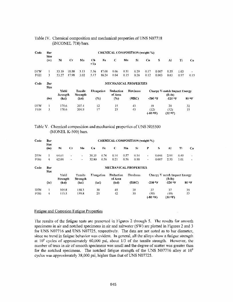
Table IV. Chemical composition and mechanical properties of UNS NO771 8 (INCONEL 718) bars.
Code Bar CHEMICAL COMPOSITION (weight %) Size (in) Ni Cr MO Ch Fe C Mn Si Cu S Al Ti Co
+Ta
DTW 1 53.19 18.88 3.13 5.36 17.00 0.06 0.31 0.29 0.17 0.007 0.55 1.03 - FGH 3 53.27 17.98 3.02 5.17 18.24 0.04 0.15 0.26 0.12 0.003 0.63 0.97 0.15
Code Bar MECHANICAL PROPERTIES Size
Yield Tensile Elongation Reduction Hardness Charpy V-notch Impact Energy Strength Strength of Area (ft-lb)
(in) (ksi) (ksi) (%I W) (HW -200 oF -120 oF 80 oF
DTW I 175.6 207.4 12 15 43 (& (:i) 22 FGH 3 178.6 204.9 17 23 43 15
(-80 OF) (32 OF)
Table V. Chemical composition and mechanical properties of UNS NO5500 (MONEL K-500) bars.
Code Bar CHEMICAL COMPOSITION (weight %) Size (in) Ni Cr MO Cu Fe C Mn Si P S Al Ti Co
DTN 1 64.61 - - 30.35 0.76 0.14 0.57 0.14 - 0.006 2.95 0.45 - FGG 4 62.00 - - 32.80 0.56 0.21 0.56 0.18 - 0.007 2.55 1.01 -
Code Bar Size
(in)
Yield Strength
(ksi)
MECHANICAL PROPERTIES
Tensile Elongation Reduction Hardness Charpy V-notch Impact Energy Strength of Area (ft-lb)
(ksi) (ksi) (ksi) (HW -200 oF -120 oF 80 oF
DTN 1 105.8 158.3 30 45 30 (2;) (ii;) 35 FGG 4 113.5 159.8 25 42 30 52
(-80 OF) (30 OF)
Fatigue and Corrosion Fatigue Pronerties
The results of the fatigue tests are presented in Figures 2 through 5. The results for smooth specimens in air and notched specimens in air and saltwater (SW) are plotted in Figures 2 and 3 for UNS NO7716 and UNS N07725, respectively. The data are not noted as to bar diameter, since no trend in fatigue behavior was evident. In general, all the alloys show a fatigue strength at lo8 cycles of approximately 60,000 psi, about l/3 of the tensile strength. However, the number of tests in air of smooth specimens was small and the degree of scatter was greater than for the notched specimens. The notched fatigue strength of the UNS NO771 6 alloy at 10’ cycles was approximately 38,000 psi, higher than that of UNS N07725.
645
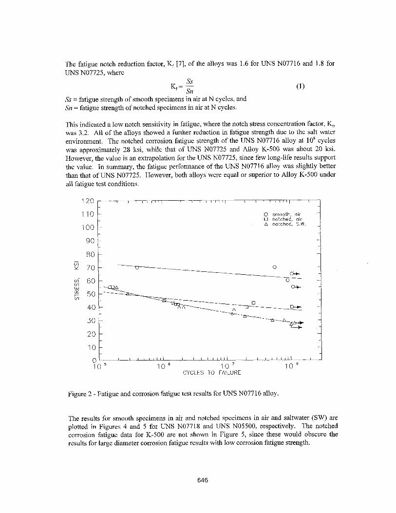
The fatigue notch reduction factor, K [7], of the alloys was 1.6 for UNS NO7716 and 1.8 for UNS N07725, where
(1) Ss = fatigue strength of smooth specimens in air at N cycles, and Sn = fatigue strength of notched specimens in air at N cycles.
This indicated a low notch sensitivity in fatigue, where the notch stress concentration factor, K, was 3.2. All of the alloys showed a further reduction in fatigue strength due to the salt water environment. The notched corrosion fatigue strength of the UNS NO7716 alloy at IO* cycles was approximately 28 ksi, while that of UNS NO7725 and Alloy K-500 was about 20 ksi. However, the value is an extrapolation for the UNS N07725, since few long-life results support the value. In summary, the fatigue performance of the UNS NO7716 alloy was slightly better than that of UNS N07725. However, both alloys were equal or superior to Alloy K-500 under all fatigue test conditions.
120r-- ’ “-” , I I Illll’ I
110 - 0 smooth, air Cl notched, oir
100 - A notched, S.W.
90 -
80 l
f2 70- c,
$ 60- w E 501
n
40 -
10 -
Figure 2 - Fatigue and corrosion fatigue test results for UNS NO7716 alloy.
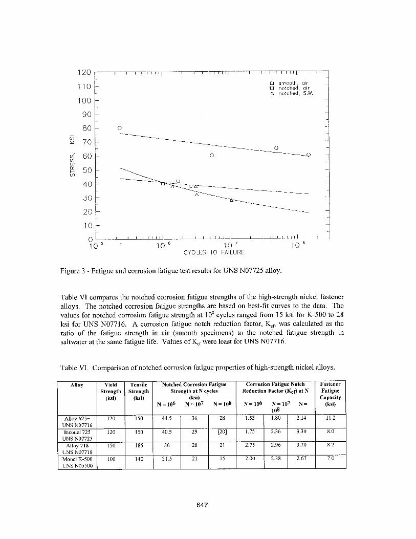
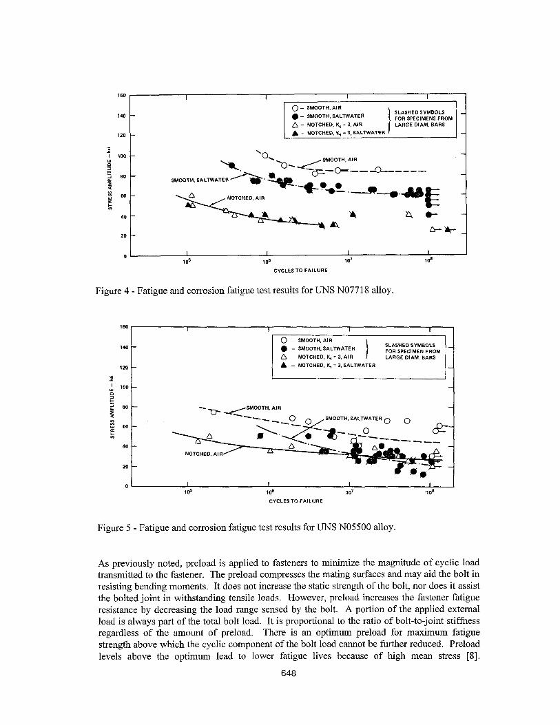
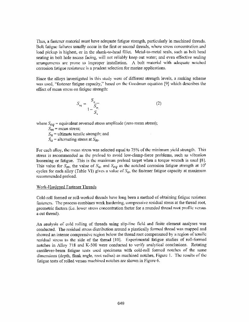
The results for smooth specimens in air and notched specimens in air and saltwater (SW) are plotted in Figures 4 and 5 for UNS NO7718 and UNS N05500, respectively. The notched corrosion fatigue data for K-500 are not shown in Figure 5, since these would obscure the results for large diameter corrosion fatigue results with low corrosion fatigue strength.
646
0 smooth, OCR 0 notched, air 4 notched, S.W.
80 0
oL1_l-I_ILdpl 1 1 1 lllll I IO5 IO6 IO' IO8
CYCLES TO FAILURE
Figure 3 - Fatigue and corrosion fatigue test results for UNS NO7725 alloy.
Table VI compares the notched corrosion fatigue strengths of the high-strength nickel fastener alloys. The notched corrosion fatigue strengths are based on best-lit curves to the data. The values for notched corrosion fatigue strength at 10’ cycles ranged from 15 ksi for K-500 to 28 ksi for UNS N07716. A corrosion fatigue notch reduction factor, K,, was calculated as the ratio of the fatigue strength in air (smooth specimens) to the notched fatigue strength in saltwater at the same fatigue life. Values of K,, were least for UNS N07716.
Table VI. Comparison of notched corrosion fatigue properties of high-strength nickel alloys.
UNSN05500 1
647
160
140
120
B 1 100
z
2 2 80
ri
2 60 : k
40
20
0
pi
I I I I
\,
SMOOTH, SALTWATER QP=qk.
I I I I
105 106 10’ ld
CYCLES TO FAILURE
Figure 4 - Fatigue and corrosion fatigue test results for UNS NO771 8 alloy.
0 I I I I I
ld 104 10’ 108
CYCLES TO FAILURE
Figure 5 - Fatigue and corrosion fatigue test results for UNS NO5500 alloy.
As previously noted, preload is applied to fasteners to minimize the magnitude of cyclic load transmitted to the fastener. The preload compresses the mating surfaces and may aid the bolt in resisting bending moments. It does not increase the static strength of the bolt, nor does it assist the bolted joint in withstanding tensile loads. However, preload increases the fastener fatigue resistance by decreasing the load range sensed by the bolt. A portion of the applied external load is always part of the total bolt load. It is proportional to the ratio of bolt-to-joint stiffness regardless of the amount of preload. There is an optimum preload for maximum fatigue strength above which the cyclic component of the bolt load cannot be further reduced. Preload levels above the optimum lead to lower fatigue lives because of high mean stress [S].
648
Thus, a fastener material must have adequate fatigue strength, particularly in machined threads. Bolt fatigue failures usually occur in the first or second threads, where stress concentration and load pickup is highest, or in the shank-to-head fillet. Metal-to-metal seals, such as bolt head seating in bolt hole recess facing, will not reliably keep out water; and even effective sealing arrangements are prone to improper installation. A bolt material with adequate notched corrosion fatigue resistance is a prudent selection for marine applications.
Since the alloys investigated in this study were of different strength levels, a ranking scheme was used, “fastener fatigue capacity,” based on the Goodman equation [9] which describes the effect of mean stress on fatigue strength:
(2)
where Se4 = equivalent reversed stress amplitude (zero mean stress); S, = mean stress; S, = ultimate tensile strength; and S, = alternating stress at S,.
For each alloy, the mean stress was selected equal to 75% of the minimum yield strength. This stress is recommended as the preload to avoid low-clamp-force problems, such as vibration loosening or fatigue. This is the maximum preload target when a torque wrench is used [S]. This value for S,, the value of S,, and Se4 as the notched corrosion fatigue strength at 10’ cycles for each alloy (Table VI) gives a value of S,, the fastener fatigue capacity at maximum recommended preload.
Work-Hardened Fastener Threads
Cold-roll formed or roll-worked threads have long been a method of obtaining fatigue resistant fasteners. The process combines work hardening, compressive residual stress at the thread root, geometric factors (i.e. lower stress concentration factor for a rounded thread root profile versus a cut thread).
An analysis of cold rolling of threads using slip-line field and finite element analyses was conducted. The residual stress distribution around a plastically formed thread was mapped and showed an intense compressive region below the thread root compensated by a region of tensile residual stress to the side of the thread [lo]. Experimental fatigue studies of roll-formed notches in Alloy 718 and K-500 were conducted to verify analytical conclusions. Rotating cantilever-beam fatigue tests used specimens with cold-roll formed notches of the same dimensions (depth, flank angle, root radius) as machined notches, Figure 1. The results of the fatigue tests of rolled versus machined notches are shown in Figure 6.
649
K-MONEL HOT FlNlSHED AND AGE HARDENED BAR loo
I I I I
AIR SALTWATER --
z so- n A MACHlNEDNOTCH.&=3 _
I 0 ROLL FORMED NOTCH, K, = 3
x 3 w- t 0’ I 4: 40-
MYNED
!
-A -_
0. I I I I I
lo6 108 10’ 1Oa
CYCLES.10 FAILURE
lNCONEL 718 SOLUTION TREATED AND AGE HARDENED BAR 100
I I I I AIR SALTWATER --
3 no- A A MACHINED NOTCH, K, = 3 ROLL FORMED
I 00 ROLL FORMED NOTCH, K, = 3
x
zw
2
i40
ii MACHINED --
g 20-
I 1 0 I I
106 106 10' 1oB
CYCLES TO FAILURE
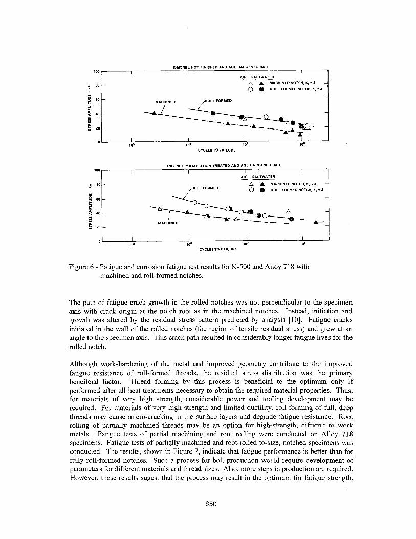
Figure 6 - Fatigue and corrosion fatigue test results for K-500 and Alloy 7 18 with machined and roll-formed notches.
The path of fatigue crack growth in the rolled notches was not perpendicular to the specimen axis with crack origin at the notch root as in the machined notches. Instead, initiation and growth was altered by the residual stress pattern predicted by analysis [lo]. Fatigue cracks initiated in the wall of the rolled notches (the region of tensile residual stress) and grew at an angle to the specimen axis. This crack path resulted in considerably longer fatigue lives for the rolled notch.
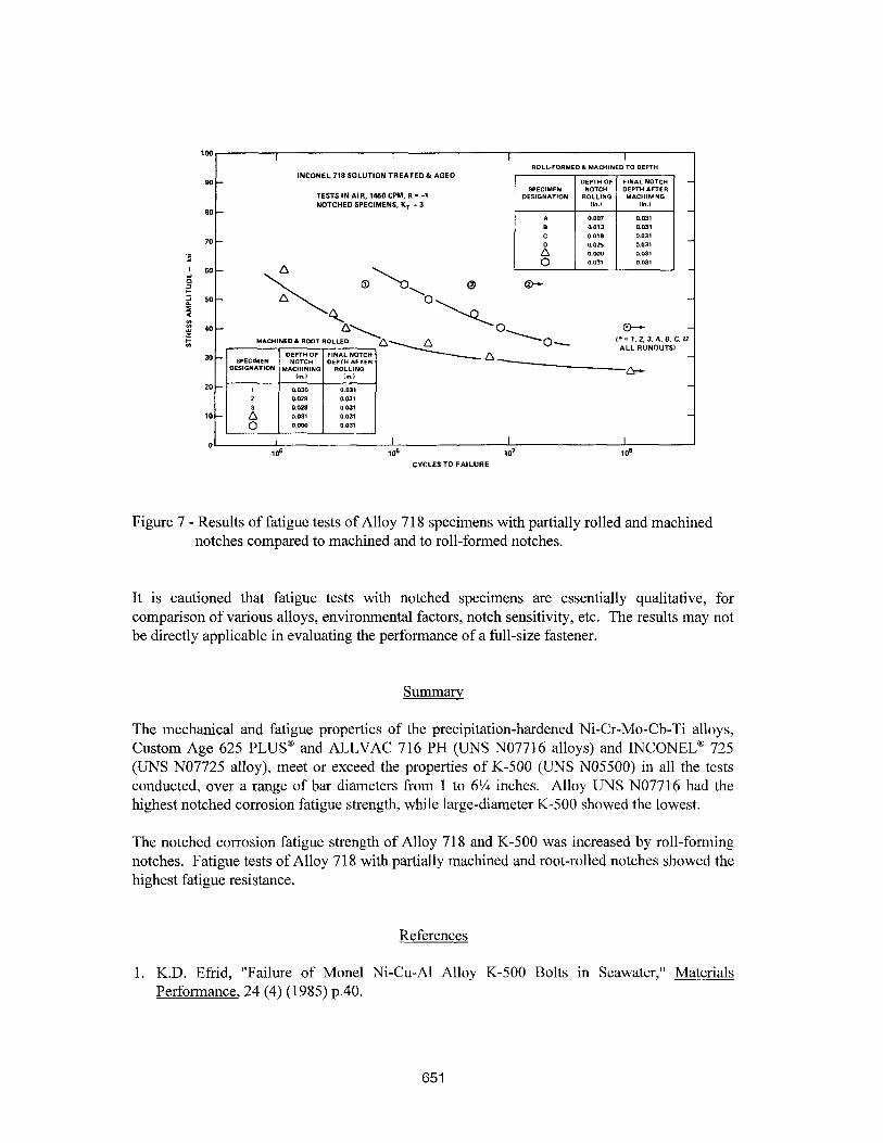
Although work-hardening of the metal and improved geometry contribute to the improved fatigue resistance of roll-formed threads, the residual stress distribution was the primary beneficial factor. Thread forming by this process is beneficial to the optimum only if performed after all heat treatments necessary to obtain the required material properties. Thus, for materials of very high strength, considerable power and tooling development may be required. For materials of very high strength and limited ductility, roll-forming of full, deep threads may cause micro-cracking in the surface layers and degrade fatigue resistance. Root rolling of partially machined threads may be an option for high-strength, difficult to work metals. Fatigue tests of partial machining and root rolling were conducted on Alloy 718 specimens. Fatigue tests of partially machined and root-rolled-to-size, notched specimens was conducted. The results, shown in Figure 7, indicate that fatigue performance is better than for fully roll-formed notches. Such a process for bolt production would require development of parameters for different materials and thread sizes. Also, more steps in production are required. However, these results sugest that the process may result in the optimum for fatigue strength.
650
INCONEL 718 SOLUTION TREATED& AGED
TESTS IN A,R, 1&5OCPM, R = -1 NOTCHED SPECIMENS. K, = 3
ld 106 107 108
CYCLES TO FAILURE
Figure 7 - Results of fatigue tests of Alloy 7 18 specimens with partially rolled and machined notches compared to machined and to roll-formed notches.
It is cautioned that fatigue tests with notched specimens are essentially qualitative, for comparison of various alloys, environmental factors, notch sensitivity, etc. The results may not be directly applicable in evaluating the performance of a full-size fastener.
Summary
The mechanical and fatigue properties of the precipitation-hardened Ni-Cr-Mo-Cb-Ti alloys, Custom Age 625 PLUS@ and ALLVAC 716 PH (UNS NO771 6 alloys) and INCONELa 725 (UNS NO7725 alloy), meet or exceed the properties of K-500 (UNS NO5500) in all the tests conducted, over a range of bar diameters from 1 to 6% inches. Alloy UNS NO7716 had the highest notched corrosion fatigue strength, while large-diameter K-500 showed the lowest.
The notched corrosion fatigue strength of Alloy 718 and K-500 was increased by roll-forming notches. Fatigue tests of Alloy 718 with partially machined and root-rolled notches showed the highest fatigue resistance.
References
1. K.D. Efrid, “Failure of Monel Ni-Cu-Al Alloy K-500 Bolts in Seawater,” Materials Performance, 24 (4) (1985) p.40.
651
2. M.W. Joosten and L.H. Wolfe, “Failures of Nickel-Copper Bolts in Subsea Applications,” Proceedings of the 19th Annual Offshore Technologv Conference, Houston, TX, Paper No. 5553 (1987), 29-34.
3. D.M. Aylor, “A Hydrogen Embrittlement Evaluation of High Strength, Non-Ferrous Materials for Fastener Application,” Proceedings of the Tri-Service Conference on Corrosion, Plymouth, MA (1982), 75-86.
4. A. Blake, Threaded Fasteners, Materials and Desipn, Marcel Dekker, Inc., New York, NY (1986).
5. A.J. Sedriks and K.L. Money, “Corrosion Fatigue Properties of Nickel-Containing Materials in Seawater,” INCO Bulletin A-1258, 5M 6-77 5705, The International Nickel Company, Inc., New York, NY (1977).
6. Manual on Fatigue Testing, ASTM STP 91, American Society for Testing Materials, Phila., PA (1949).
7. R.E. Peterson, Stress Concentration Factors, John Wiley & Sons, Inc, New York, NY (1974).
8. J.H. Bickford, “Bolt Torque: Getting it Right,” Machine Design, June (1990), 67-7 1.
9. J. Goodman, Mechanics Anplied to Engineering, (l), 9th edition, Longmans Green, London, U.K. (1930).
10. M.G. Vassilaros and H. Kuhn, “Analysis of the Residual Stresses Resulting from Cold- Rolling of Threads and Their Effect on Fatigue Behavior,” Proceedings of the 7th North American Metalworking Conference (1979), 96-99.
652