FASTRAK® USER'S MANUAL Revision F · PDF fileOPM3609-002C November 1993 1 FASTRAK USER'S...
90
3SPACE® OPM3609-002C November 1993 FASTRAK® FASTRAK® USER'S MANUAL USER'S MANUAL Revision F Revision F
Transcript of FASTRAK® USER'S MANUAL Revision F · PDF fileOPM3609-002C November 1993 1 FASTRAK USER'S...

3SPACE®
OPM3609-002C November 1993
FASTRAK®FASTRAK® USER'S MANUALUSER'S MANUAL Revision FRevision F
OPM3609-002C November 1993
NOTICE Copyright ©1992-1993 by Polhemus Incorporated Colchester, Vermont U.S.A. All rights reserved. No part of this publication may be reproduced, stored in a retrieval system, or transmitted, in any form or by any means, mechanical, photocopying, recording or otherwise, without the prior written permission of Polhemus Incorporated. No patent liability is assumed with respect to the use of the information contained herein. While every precaution has been taken in the preparation of this book, Polhemus Incorporated assumes no responsibility for errors or omissions. Neither is any liability assumed for damages resulting from use of the information contained herein. 3SPACE® and FASTRAK® are registered trademarks of Polhemus Incorporated.
OPM3609-002C November 1993
WARNING This equipment has been tested and found to comply with the limits for a Class A digital device, pursuant to part 15 of the FCC Rules. These limits are designed to provide reasonable protection against interference when the equip-ment is operated in a commercial environment. This equipment generates, uses, and can radiate radio frequency energy and, if not installed and used in accordance with the instruction manual, may cause interference to radio communications. Operation of this equipment in a residential area is likely to cause interference in which case the user will be required to correct the interference at his own expense.

OPM3609-002C November 1993
vi
SOFTWARE COMMAND STRUCTURE COMPARISON FASTRAK vs TRACKER For our customers who presently own one or more of our Tracker products and either have or are considering up-grading to a FASTRAK instrument, we are pleased to present a software command structure comparison between the Tracker and the new FASTRAK. This is not a detailed, bit by bit comparison - you will have to refer to the command data presented within the FASTRAK manual to obtain that level of detail. What we do show however, are all the commands by letter and title (old and new) in four major categories called "Same", "Modified", "Deleted" and "New". In the "Modified" category, where some of the commands themselves may not have been changed, modifications were made to their output structure. 1.0 Same Cmnd Ltr Fastrak Title Tracker Title A Alignment Reference Define Alignment Frame from Host R Reset Alignment Reset Alignment Reference Frame B Boresight Define Boresight b Unboresight Reset Boresight ^K Save Operational Save System Configuration State F Enable ASCII Output Set ASCII Data Format Format ^Y Re-initialize System System Reset P Single Record Send Record Transmission C Continuous Print Set Continuous Output Xmit Mode c Disable Continuous Set Non-
OPM3609-002C November 1993
vii
Printing continuous Xmit Mode U Set Unit Inches Set Inches Unit u Metric Conversion Set Centimeter Units Units ^S Suspend Data Suspend Xmission Xmission (X/OFF) ^Q Resume Data Resume Xmission Xmission (X/ON) v Attitude Filter Attitude Filter Parameters Parameters x Position Filter Position Filter Parameters Parameters V Position Operation- Define Envelope al Envelope 2.0 Modified Cmnd Ltr Fastrak Title Tracker Title e Define Stylus Button Run Digitizer Function Mode f Enable Binary Set Binary Data Output Format Format I Define Increment Define Increment O Output Data List Define Output List S System Status System Status l Active Station State Station Acti vate/Deactivate H Hemisphere of Define Hemi- Operation sphere from Host N Define Tip Offsets Define Tip Offsets

OPM3609-002C November 1993
viii
3.0 Deleted Cmnd Ltr Fastrak Title Tracker Title a Define Output List k Reset Output List t Extended Mode 4.0 New Cmnd Ltr Fastrak Title G Boresight Reference Angles D Enable Fixed Metal Compensation d Disable Fixed Metal Compensation r Transmitter Mounting Frame y Set Synchronization Mode W Reset System to Defaults X Configuration Control Data Q Angular Operational Envelope o Set Output Port T Built-In-Test Information
OPM3609-002C November 1993
ix
GETTING STARTED There are two ways to get started with your FASTRAK instrument as with any new instrument. You could "wing it," which involves a great deal of assumptions based on either previous experience and/or visual inspection, and hope for the best. Or, you could sit down and read the whole manual, line-by-line, and then start. The former method inevitably leads to massive amounts of frustration and irritation and is bad for your blood pressure. The latter method, if followed exactly, will either lead to eventual success or completely cure your insomnia which in either case will be unacceptably time consuming. The following is offered as an alternative approach. However, this approach does not preclude using the manual as a precise guide, reference and final arbiter. NOTE: This approach assumes a single receiver, use of the RS-232 serial port at 9600 Baud communicating with a PC through Comm1, and use of the TERMINAL program located on the accompanying diskette. 1. Do visually and carefully inspect the instrument and the accompanying receiver(s) and transmitter. Note external switches and port numbering. If you have any questions concerning these items refer to Section 5 in the manual. 2. Set up the instrument close to your host computer and away from large metal objects like file cabinets, metal desks etc. 3. Identify the transmitter and insert the

OPM3609-002C November 1993
x
transmitter connector into its appropriate port, being careful to firmly engage it. Using a small, flat bladed screw driver, lock the connector by seating the two retaining screws. 4. For getting started, use only one receiver. Identify the receiver and insert the receiver connector into Receiver Port #1. Firmly engage and lock the receiver connector into place in the same manner as the transmitter connector in Step 3 above. 5. Identify the "Receiver Inputs/Selector Switch". This switch is located on the front panel of the electronics unit between receiver ports #1 and #3. Locate switch #1 and place it in the DOWN position. Ensure that all remaining (three) switches are in the UP position. 6. For testing purposes, it is convenient to mount both the transmitter and the receiver on a single block of wood (2X4 or equivalent) about 14 inches apart. Exact placement of the transmitter and receiver is not particularly important; just make sure the cable ends of both devices come off the small ends of the 2X4. 7. Identify the five pin "DIN" type power input connector on the back panel of the electronics unit. With the separate Power Supply ("brick") UNPLUGGED from the wall's convenience outlet, plug the "brick's" DIN connector into the power input connector on the rear panel of the electronics unit and firmly seat. Identify the power ON/OFF rocker switch located on the rear panel of the electronics unit. Ensure this switch is in the OFF position (logic "0" and DOWN) before inserting the "brick's" convenience plug into the 110/220 VAC outlet.
OPM3609-002C November 1993
xi
8. Identify the I/O Select Switch located on the rear panel of the electronics unit. Set the switches to the following positions: Switch Position 1 UP 2 UP 3 DOWN 4 DOWN 5 UP 6 DOWN 7 DOWN 8 UP As set, these switches provide for RS-232 serial operation (Switch 8), 9600 baud (Switches 1, 2 & 3), 8 bit character width (Switch 5), no parity (Switches 6 & 7), and no hardware handshake (RTS, CTS) functionality (Switch 4). 9. NOTE: THE FASTRAK INSTRUMENT THINKS IT IS A TRANSMITTER AND THEREFORE A NULL MODEM CABLE IS REQUIRED. Obtain a NULL MODEM RS-232 serial interconnection cable with a 9 pin, female "D" connector on both ends. Plug one 9 pin, female "D" connector into the I/O connector located on the rear panel of the electronics unit. Engage and lock this connection in the same manner as the receiver and transmitter connections as indicated in Steps 3 & 4 above. 10. Most PC hosts have a 9 pin, male "D" type connector for Comm1. Therefore, because we are using Comm1, plug the remaining end of the cable into the Comm1 port of the host PC and engage and lock as before. If your host computer has a 25 pin "D" connecter for the RS-232 port, you will need a 9 to 25 pin "D" connecter adaptor with the proper genders.

OPM3609-002C November 1993
xii
Note that this adapter must not compromise the NULL MODEM sense of your cable. 11. Insert the Terminal Program diskette into the "A" drive, obtain the A drive prompt (A:\) and type "terminal" followed by a carriage return. When the Terminal program comes up, first refer to the READ.ME and TERMINAL.DOC files contained in this program so you will be familiar enough with the program to exercise the instrument. 12. At this point you may turn on the FASTRAK using the Power Switch located on the back panel of the S.E.U. Note the Power On Indicator located on the front panel of the electronics unit. It should flash for approximately 10 seconds indicating self-test and set-up. When these routines are completed (@10 seconds), the indicator will turn to a steady-on state thereby indicating that the instrument is ready to operate. 13. You may now use the Terminal Program to exercise the instrument. The six-degree-of-freedom output data you receive consists of seven columns of data as follows: Column Function 1 01 2 X position in inches 3 Y position in inches 4 Z position in inches 5 Azimuth attitude in degrees 6 Elevation attitude in degrees 7 Roll attitude in degrees Because you have locked the receiver in one position relative to the transmitter (Step 6), the data output
OPM3609-002C November 1993
xiii
will not change regardless of the number of data samples you take. 14. Loosen the receiver and move it approximately six inches toward the transmitter and take a data point. The value of the X position data will decrease by approximately six inches. The Y and Z values will remain roughly the same as the original data. If you left the attitude of the receiver approximately the same as it was when you started, then the attitude data will be approximately the same also. 15. Again, loosen the receiver and without moving its position, try twisting it in YAW (azimuth) approximately 45 degrees and lock it down with tape. Now take another data point. The first four columns will be approximately as they were in Step 13, but the Azimuth data in column 5 will have changed approximately 45 degrees. 16. Play with the instrument as shown in Step 14 to demonstrate that it measures the position and orientation (six-degrees-of-freedom) of the receiver with respect to the transmitter. 17. If the instrument fails to produce six-degree-of-freedom data, carefully go over the above procedure in a step-by-step fashion, checking connections and switch settings especially. When all else fails, call us.

OPM3609-002C November 1993
1
FASTRAK USER'S MANUAL 1.0 INTRODUCTION Welcome to the world of FASTRAK! We have streamlined our electromagnetic, six-degree-of-freedom tracking instrument to give you the latest and best tracking performance machine anywhere. Hopefully we have accomplished these attributes in our manual as well. The data presented here allows you to move into the FASTRAK lane with the speed you desire. You won't be hindered by excessive and formal verbiage. Only the pertinent facts are presented. 2.0 HARDWARE The FASTRAK instrumentation consists of the following standard and optional items: Standard Items 1. System Electronics Unit (SEU) 4A0316-01 w/single carrier frequency capacitor board installed 2. Power Supply, Free Standing 1C0034 International Power Sources 3. Transmitter with 10' cable 3A0369-02 4. Single Receiver with 10' Cable 4A0314-01 5. FASTRAK Manual OPM3609-002C 6. FASTRAK Interface Diskette (FID)
OPM3609-002C November 1993
2
Optional Items 1. RS-422 serial port in lieu of RS-232C port. 2. Up to three additional Receivers. 3. Any of three alternate Frequency Select Modules. (3A0363-01, 02, or 04) 4. Inter-Unit Synchronization Cables: Standard telephone extension cable (H1643-14.ND) 5. Video Sync Detector. (36-010) 6. Transmitter with 20' Cable. (3A0369-03) 7. Receiver with 20' Cable. (4A0314-02) 8. Transmitter with 1' break-away cable. (3A0369-04) 9. Receiver with 1' break-away cable. (4A0314-03) 10. Stylus with 10' or 20' Cable (4A0318-01 or 02) 11. 3BALL (receiver) with 10' cable (4A0314-05) 3.0 OVERVIEW The FASTRAK tracking system uses electro-magnetic fields to determine the position and orientation of a remote object. The technology is based on generating near field, low fre-quency, magnetic field vectors from a single assembly of three colocated, stationary antennas called a transmitter (Xmtr), and detecting the field vectors with a single assembly of three colocated, remote sensing antennas called a receiver (Rcvr). The sensed signals are input to a mathematical algorithm that computes the receiver's position and orientation relative to the transmitter. The FASTRAK consists of a System Electron-ics Unit (SEU), one to four receivers, a single transmitter, and a power supply. The system is

OPM3609-002C November 1993
3
capable of operating at any of four discrete carrier frequencies. Different carrier frequencies allow operation of up to four FASTRAKs simultaneously and in close proximity to one another. The FASTRAK has two possible interfaces to your host computer: RS-232 and IEEE-488. Any single receiver may be operated at the fastest update rate (120 Hz); any two receivers at one half this rate; any three at one third this rate; or all four at one fourth the fastest rate. Mixed rates are not permitted meaning that all active receivers operate at the same update rate; one cannot be operated faster than another. Active receivers are selected by a combination of software configuration commands and receiver selector switch settings. Additionally, the FASTRAK may be used with a stylus or a 3BALL device in lieu of a standard package receiver. Tip offsets are automatically calculated for the stylus and no special commands are required for this mode of operation. Switch functionality is provided with both the stylus or 3BALL device. The stylus and 3BALL may only be used in Receiver Port #1. Operation of these devices is covered in Section 6.11.
OPM3609-002C November 1993
4
4.0 SPECIFICATION Position Coverage The instrument will provide the specified accuracy when the receivers are located within 30" (76 cm.) of the transmitter. Operation with separations up to 120" (305 cm.) is possible with reduced accuracy. Angular Coverage The receivers are all-attitude. Static Accuracy 0.03" (0.08 cm) RMS for the X,Y,or Z receiver position, and 0.150 RMS for receiver orientation. Resolution 0.0002 inches/inch of range (0.0005 cms/cm of range), and .0250. Latency 4.0 milliseconds from center of receiver measurement period to beginning of transfer from output port. Output Software selectable including extended precision. Cartesian coordinates of position and Euler orientation angles are standard. Direction cosines and quaternions are selectable. English or metric units are also selectable. Update Rate

OPM3609-002C November 1993
5
One receiver: 120 updates/second/receiver Two receivers: 60 updates/second/receiver Three receivers: 40 updates/second/receiver Four receivers: 30 updates/second/receiver Carrier Frequency The FASTRAK may be configured with any one of four discrete carrier frequen-cies to allow simultaneous operation of up to four instruments in close proximity. Carrier frequencies are selected via color coded Frequency Select Modules (FSM). These frequen-cies are: Reference # Frequency Color Code 1 8013 Hz Black 2 10016 Hz Red 3 12019 Hz (Standard) Yellow 4 14022 Hz Blue The color dot can be found on the FSM, on the end closest to the connector. Interfaces IEEE-488 parallel port at 100K Bytes/second maximum, and RS-232C serial port with software selectable baud rates of 300, 1200, 2400, 4800, 9600, 19200, 38400, 58600 and 115200; ASCII or Binary format. The factory standard for RS-232C is 9600 baud. An RS-422 port is available as an optional serial port in lieu of the RS-232 at the same baud rates. Operating Environment Large metallic objects, such as desks or cabinets, located near the transmitter or receivers may adversely affect the performance of the instrument.
OPM3609-002C November 1993
6
Operating Temperature 100C to 400C at a relative humidity of 10% to 95% non-condensing. Physical Characteristics SEU Width 11.38" (28.91 cm.), length 11.06" (28.90 cm.), height 3.63" (9.22 cm.), weight 5.0 lb. (2.26 Kg.). Transmitter Width 2.1" (5.3 cm.), length 2.1" (5.3 cm.), height 2.3" (5.8 cm.), weight 0.6 lb. (0.27 Kg.) excluding attached cable. The Trans-mitter may be purchased with either 10' or 20' cables or with a 1' cable with break-away connector. Receiver Width 1.1" (2.83 cm.), length 0.90" (2.29 cm.), height 0.60" (1.52 cm.), weight 0.6 oz. (17.0 gm.) excluding attached cable. Receivers may be purchased with either 10' or 20' cables, or with a one-foot cable with break-away connector. Stylus Length 7.75" (19.7 cm.) including tip, maximum barrel diameter 0.75" (1.9 cm.), handle diameter 0.375" (0.95 cm.), tip length 1.00" (2.54 cm.), tip diameter 0.156" (0.4 cm.), weight 2.5 oz. (28.3 gm.) excluding attached cable. The stylus may be purchased with either 10' or 20' cables. 3BALL A standard receiver mounted in an official #3 billiard
OPM3609-002C November 1993
7
ball fitted with an integral switch. The 3BALL has a standard 10' cable. Power Requirements International Power Sources Supply: Input power is 85-264 VAC, 47-440 Hz, single phase at 25 watts.
OPM3609-002C November 1993
8
5.0 COMPONENT DESCRIPTION 5.1 SEU The SEU is a stand-alone unit that may be located anywhere that is convenient to the work area, AC power and the host computer. It contains the required input and output con-nectors and controls to support up to four receivers, a single transmitter and the RS-232 and IEEE 488 output ports. Receiver Input(s), Rcvr Select Switch, Transmitter Input, I/O Cables, I/O Select Switch, External Sync I/O, Video Sync Input, and Power Input connec-tions are located on the SEU as shown in Figure 1 and Figure 2. 5.2 Receiver Inputs/Selector Switch The four possible Receiver Input recep-tacles are 15 pin, female, "D" type designated 1, 2, 3, and 4 and are located on the SEU as shown in Figure 2, Front View. Any one or all four Receivers may be plugged in. Receiver selection is accomplished by the four position receiver Selector Switch located on the SEU as shown in Figure 2, Front View. To select a particular Receiver, the corresponding number selector switch must be DOWN and all others UP. Improper receiver switch selection or failure to select at least one receiver will result in a continuous output to the RS-232 port of "1" type output records (ACTIVE STATION STATE).

OPM3609-002C November 1993
9
Figure 1. FASTRAK Instrument
OPM3609-002C November 1993
10
Figure 2. FASTRAK SEU

OPM3609-002C November 1993
11
5.3 Transmitter Output The single Transmitter Output receptacle is a 15 pin, male "D" type located on the front of the SEU as shown in Figure 2. 5.4 Power Indicator A green LED power on indicator is located on the front of the SEU as shown in Figure 2. Upon power up the indicator will blink for approximately 10 seconds while the instrument performs its initialization and self test routines. When these routines are complete the indicator changes from blink mode to steady-on and the instrument is ready for operation. 5.5 I/O Select Switch The I/O Select Switch is an 8 position switch located on the rear panel of the SEU as shown in Figure 2, Rear View and is only read on power up. The purpose of this switch is to select the I/O to be used -- IEEE-488 parallel mode or RS-232 serial mode. Switch number 8 selects the desired mode and the remaining 7 switches have dual functionalities depending on the mode selected. The modes with switch positions and their corresponding functions are: Parallel Mode -- IEEE-488 Note: UP position is a logic "1" and DOWN is a logic "0". Switch Position Function
OPM3609-002C November 1993
12
1 Bit 0 (LSB) IEEE-488 Address 2 Bit 1 IEEE-488 Address 3 Bit 2 IEEE-488 Address 4 Bit 3 IEEE-488 Address 5 Bit 4 (MSB)IEEE-488 Address 6 not used 7 not used 8 I/O Select -- DOWN for IEEE-488 Serial Mode -- RS-232 Note: UP position is a logic "1" and DOWN is a logic "0". Switch Position Function 1 Baud rate select 2 Baud rate select 3 Baud rate select 4 Hardware Handshake select 5 Character width: "0" = 7 bits "1" = 8 bits 6 Parity select 7 Parity select 8 I/O Select -- UP for RS-232 The Baud rate select logic for switches 1, 2 and 3 is as follows:

OPM3609-002C November 1993
13
Baud Rate 1 2 3 1200 0 0 0 2400 1 0 0 4800 0 1 0 9600 1 1 0 19200 0 0 1 38400 1 0 1 57600 0 1 1 115200 1 1 1 The instrument reads the baud rate switches only on power up. Therefore, if you change the switches to obtain a different baud rate, you must restart the instrument either by using the ^Y command or by recycling the power. The "o" command may be used to override the switch settings during operation. However, even if you save the new baud rate with the ^K command, the next time you power up, the instrument will ignore the EEPROM baud rate setting and read the switch settings to operate at that baud rate. The Hardware Handshake function, when evoked by Switch 4, enables the Request To Send (RTS) and Clear To Send (CTS) serial interface handshake functions for those host computers that would better operate utilizing them. The Hardware Handshake select logic for switch 4 is "0" = RTS/CTS Disabled "1" = RTS/CTS Enabled. The Parity select logic for switches 6 and 7 is as follows:
OPM3609-002C November 1993
14
Parity 6 7 None 0 0 Odd 1 0 Even 0 1 not used 1 1 if selected - system defaults to Even parity. 5.6 External Sync I/O The External Sync I/O module is located on the rear edge of the SEU as shown in Figure 2. The module contains two modular telephone plugs with the plug closest to the I/O Select Switch being "Sync In". All input and output signals must be differential TTL compatible signals with the following logic: Input: START = Logic LOW to HIGH transition, 50
1sec. pulse, min. Output: START = Logic HIGH, 50 1sec. pulse, min. The Sync In and Sync Out signals use differential receivers and drivers which are compatible with RS-422 specifications. The pin assignments for each plug are as follows and their numbering is shown in Figure 3: "Sync In" Pin # Function 4 SYNC IN POSITIVE 3 SYNC IN NEGATIVE 2 GROUND 1 INTERNAL USE

OPM3609-002C November 1993
15
Figure 3. FASTRAK Controls/Connections (Front & Rear)
OPM3609-002C November 1993
16
"Sync Out" Pin # Function 4 INTERNAL USE 3 GROUND 2 SYNC OUT NEGATIVE 1 SYNC OUT POSITIVE 5.7 IEEE-488 I/O The IEEE-488 I/O receptacle is a standard IEEE-488, 24 contact, female, "D" type located on the rear edge of the SEU as shown in Figure 2. 5.8 Frequency Select Module The Frequency Select Module is used to select the operating carrier frequency of choice. It is located on the PCB directly behind the Transmitter input connector. The alternate carrier frequencies are produced by inserting the required capacitor module in the socket provided. The Frequency Select Modules are color coded for carrier frequency identification as described in Section 4.0 of this document. AS WITH ANY HANDLING OF THE PCB, WHEN INSERTING OTHER MODULES TO EFFECT A DIFFERENT CARRIER FREQUENCY, STATIC PRECAUTIONS MUST BE OBSERVED. DO NOT REMOVE AND REPLACE FREQUENCY SELECT MODULE WITH POWER APPLIED TO THE PCB. 5.9 RS-232 I/O The RS-232 I/O connector is a standard, 9 pin, male, "D" connector located on the rear of the SEU as

OPM3609-002C November 1993
17
shown in Figure 2. The pinouts for this connector are as follows: Pin # Function 1 not used 2 RxD 3 TxD 4 not used 5 GND 6 not used 7 RTS* 8 CTS* * Selected via Switch 4 of I/O Select Switch FASTRAK optionally uses RTS and CTS which is enabled via the I/O Select Switch. Please refer to Appendix D to find the specific interconnection scheme for your host and the corresponding action that must be taken to obtain a reliable serial interface. NOTE: If you do not find your particular host's RS-232 I/O interconnection scheme in Appendix D, call Polhemus and FAX a copy of your host's pinout scheme from its user's manual. Polhemus will respond with the appropriate action you must take to allow your FASTRAK and host to communicate. (Our FAX number can be found in Section 9.) 5.10 Optional RS-422 I/O The optional RS-422 connector is identical to the RS-232 connector in form, fit, function, and location on the rear of the SEU. RS-422 is a differential transmit and receive I/O with a maximum speed of 10 Megabits/second with operation possible at a distance
OPM3609-002C November 1993
18
of 1200 meters with a speed of 100Kbits/second. The RS-422 does not use Handshake functions for transmission and reception. The pinouts for this connector are as follow: Pin # Function 1 RxB; non-inverting receive input 2 not used 3 not used 4 TxB; non-inverting transmit output 5 not used 6 RxA; inverting receive input 7 not used 8 not used 9 TxA; inverting transmit output 5.11 Video Sync Input The Video Sync Input is a subminiature telephone receptacle that mates with the video pickup coil assembly (Video Sync Detector). The Video Sync Input is located on the rear of the SEU as shown in Figure 2. 5.12 Power Input Receptacle The Power Input is a 5 contact, female, shielded DIN type receptacle located on the rear of the SEU as shown in Figure 2. Pinouts for this receptacle are as follows: Pin # Function 1 COMMON

OPM3609-002C November 1993
19
2 GROUND 3 +5 VDC 4 -15 VDC 5 +15 VDC Note: Pin 1 is electrically shorted to Pin 2 on the PCB. 5.13 Cooling Fan A small cooling fan is located on the rear panel of the SEU as shown in Figure 2. The fan is powered from the 5 VDC supply and will only operate when the instrument is powered up. 5.14 Transmitter The Transmitter is dimensionally shown in Figure 4 including the position of the electrical center. There are 4, 1/4" - 20 NC tapped holes provided on the bottom surface for mounting. Nylon hardware (supplied) should be used when locating the Transmitter in a fixed position.
OPM3609-002C November 1993
20
Figure 4. Transmitter

OPM3609-002C November 1993
21
5.15 Receiver(s) The Receiver is dimensionally shown in Figure 5 including the position of the electrical center. The Receiver package provides 2 mounting holes for #4 screws (supplied) in the event that Receiver mounting is required. In this case, the supplied nylon hardware is required. 5.16 Stylus The stylus is dimensionally shown in Figure 6 and may only be used in Receiver port #1. The stylus functions as a receiver with the electrical center offset to the tip of the stylus via software and single or continuous output records may be obtained as a function of the integral switch. See Section 6.11 for operation with a stylus. 5.17 3BALL The 3BALL is a receiver mounted in a #3 billiard ball which contains an integral switch. The 3BALL is shown in Figure 7 and may be used in the same manner as a mouse, in that single or continuous output records may be obtained as a function of the switch. The 3BALL may only be used in port #1. See Section 6.11 for operation with the 3BALL device.
OPM3609-002C November 1993
22
Figure 5. Receiver

OPM3609-002C November 1993
23
Figure 6. Stylus
OPM3609-002C November 1993
24
Figure 7. 3BALL

OPM3609-002C November 1993
25
5.18 Video Sync Detector The Video Sync Detector consists of a pickup coil and a 3' cable terminated with a subminiature telephone plug. The Video Sync is used when the instrument's data exhibits objectionable noise when operating a receiver in close proximity to any CRT monitor. If this condition occurs, then Video Sync may be employed using the Video Sync Detector (see Section 5.9) and the software command "y2" (see Section 7.5 - Set Synchronization Mode). The pickup coil of the Video Sync Detector is attached to the CRT (Monitor) case and the connector inserted into the Video Sync Detector input. After issuing the "y2" command, the instrument checks for sufficient signal level from the video pickup coil. If the signal level from the pickup coil is below a preset threshold, a "no video sync available" message is displayed. If this condition exists, move the pickup coil to another part of the Monitor case. This procedure is repeated until the "no video sync available" message ceases to occur. The video synchronization mode may be exited at any time by selecting another type of synchronization mode using the "y" command. 5.19 Diskette There is one diskette that accompanies this instrument called a FASTRAK Interface Diskette (FID). The Terminal Program allows PC host/ instrument communication, testing and data collection without detailed knowledge of various system commands and contains the following program and files: 1. Terminal Emulator Program for instrument
OPM3609-002C November 1993
26
communication. 2. READ.ME file. 3. TERMINAL.DOC file that describes functionality. 4. Source Code for use by an experienced programmer.

OPM3609-002C November 1993
27
6.0 INSTRUMENT OPERATION 6.1 I/O Considerations Perhaps one of the most confusing and frustrating areas to deal with is interfacing the FASTRAK instrument to the host computer, because, if that isn't properly accomplished, then absolutely nothing happens. This section of the manual is an attempt to make that integration task as painless as possible. As stated in Section 5, there are three possible interface ports; IEEE-488 parallel, RS-232C serial and an optional serial RS-422. Each port supports either Binary or ASCII formats. Only the two serial ports and their interconnections with the host computer are discussed here. Requirements for and use of the IEEE-488 parallel port are discussed in Appendix A. RS-232C The RS-232 is the most commonly used port both in binary and ASCII formats because of its commonality and the fact that it supports high baud rates. The RS-232 port should be used where host to FASTRAK physical separation distances are no greater than 50 feet. There are two modes of operation with the RS-232; with Hardware Handshake (HH) and without HH. In Step 9 of the "Getting Started" section, we said that it is necessary to use a "null modem" cable because the instrument thinks it is a transmitter. If this is confusing to you here is a nearly universal approach to connecting the FASTRAK to your host computer via the RS-232 I/O Port. For operation without Hardware Handshake, ensure that your RS-232 cable connects the FASTRAK TRANSMIT DATA PIN (TxD) to the HOST'S RECEIVE DATA PIN and that the FASTRAK RECEIVE DATA PIN (RxD) is connected to the
OPM3609-002C November 1993
28
HOST'S TRANSMIT DATA PIN. Also ensure that the RS-232 cable connects the FASTRAK GROUND PIN (GND) to the HOST'S GROUND PIN. Note that the host's ground pin may be designated as "Signal Ground" or some other comparable phrase. Also, ensure that the I/O Select Switch switches are set exactly as shown in Item 8 of the "Getting Started" Section of this manual. For operation with Hardware Handshake, the above connections must be made plus the following additional connections and change in switch settings. First, ensure that your RS-232 cable connects the FASTRAK CTS (CLEAR-TO-SEND) PIN to the HOST'S DTR (DATA-TERMINAL-READY) PIN and the FASTRAK RTS (REQUEST- TO-SEND) PIN is connected to the HOST'S DSR (DATA-SET-READY) PIN. Next, place switch #4 of the I/O Select Switch in the UP position. Please note however that your host may call the DTR and DSR functions by other similar names. RS-422 The optional RS-422 port is used where large separation distances between the FASTRAK and the host are anticipated. The RS-422 does not use Hardware Handshaking and failure to place switch #4 of the I/O Select Switch in the DOWN position will render the port inoperable. As with the RS-232 port, the RS-422 Transmit signals from the FASTRAK must be connected to the Host's Receive signals and the FASTRAK's Receive signals must be connected to the Host's Transmit signals. Signal polarity conventions must be strictly observed. 6.2 Setup After assembling the instrument hardware and connecting the I/O cable to the host computer, the

OPM3609-002C November 1993
29
TERMINAL.EXE program may be used to communicate with and operate the FASTRAK instrument. Please note: Once you have established the transmitter/receiver configuration and set the Selector Switch, the configuration is set until you change it. If at any time you decide to change the configuration or add additional or new receivers/transmitters, it must be accomplished with power OFF as receiver/transmitter characterization data is only read at power up. Failure to do this will result in erroneous data. 6.3 Power-Up The FASTRAK has a power on switch. To power-up your instrument first ensure that the power supply is not plugged into the AC. Then connect the power cable from the Power Supply to the DIN power connector on the rear panel of the instrument. Plug the Power Supply into the AC outlet and turn the Power Switch to the ON position. On power up, the power indicator will blink for approximately 10 seconds to indicate the instrument's performance of an initialization and self test routine. During this time instrument operation is not possible. At the completion of this routine, the power indicator will change from a "blink" state to "steady-on" which indicates that the instrument is now operational. 6.4 Output Considerations Operating the instrument consists of issuing commands over either I/O port from the host to control the instrument's performance characteristics and observing and/or utilizing the resulting outputs. The most important parameters describing the instrument's performance are latency, speed, accuracy and
OPM3609-002C November 1993
30
resolution. Definitive treatment of these parameters is contained in two application notes found in Appendices B and C of this document. They are entitled: "ACCURACY AND RESOLUTION IN ELECTROMAGNETIC SIX-DEGREE-OF-FREEDOM MEASUREMENT SYSTEMS", and "Technical Note LATENCY - 3SPACE® FASTRAK." From an operational point of view relative to the instrument output, latency must be considered with respect to baud rate, output record length and filtering. The combination of baud rate, record length and filtering collectively define the data transfer time. Depending on the baud rate, record length and filtering chosen, longer than specified latency, exclusive of data transfer time, will occur. If the data transfer time is longer than the instrument's cycle time and data queuing is invoked in the output buffer, an output data record may be skipped. For example: if the instrument is operated in continuous print mode ("C" command) and the data transfer time is longer than the cycle time, the instrument will skip a data record or queue the data for output depending on the output buffer availability for the RS-232 port only. For the IEEE-488 port, however, output is immediate if the output buffer is available; if not, the data record is skipped. Additionally, if more than one receiver is in use, the receiver output sequence will not be compromised due to output buffer availability. If output data is requested with the "P" command (single record), regardless of the I/O port employed, and the time between requests is less than the instrument cycle time, no delays will result from queuing and no data record skipping will occur since only one full data record at a time will reside in the output buffer. 6.5 Synchronization and Multiple Systems

OPM3609-002C November 1993
31
Synchronization Synchronization defines and controls the precise time that a FASTRAK instrument measurement cycle will start and thereby controls the tracking output from an application system point of view. The FASTRAK instrument has three distinct synchronization modes that are controlled by the "y" commands and are defined as: MODE COMMAND Internal Sync y0 External Sync y1 Video Sync y2 $ Internal Sync In the Internal Sync mode (y0 command), each measurement cycle of the FASTRAK instrument starts immediately after the previous cycle ends. The instrument update rate is slightly greater than 120 Hz and cycle-to-cycle variations on the order of microseconds are possible in this mode. Only the "y0" command is required to initiate the Internal Sync mode and no input is required for the instrument's SYNC IN port. $ External Sync The External Sync mode (y1 command), allows you to define when the FASTRAK instrument measurement cycle will start. This mode may be used to synchronize other peripheral instrumentation to the FASTRAK data collection cycle or to slow the FASTRAK to a known and desired rate. To initiate the External
OPM3609-002C November 1993
32
Sync mode an external signal as detailed in Section 5.5 must be input to the SYNC IN port and the "y1" command issued. WARNING ONCE THE FASTRAK INSTRUMENT IS PLACED IN THE EXTERNAL SYNC MODE BY ISSUING THE "y1" COMMAND AND THE INSTRUMENT RECEIVES A SYNC PULSE, THE FASTRAK WILL IGNORE ANY SYNCHRONIZATION PULSES SENT DURING RESULTING MEASUREMENT CYCLES. WHEN THE MEASUREMENT CYCLE IS COMPLETE, THEN AND ONLY THEN WILL THE INSTRUMENT HONOR THE NEXT SYNC PULSE. IF YOU ARE CONTEMPLATING CHANGING SYNCHRONIZATION MODES DURING YOUR COURSE OF OPERATION WITH THE FASTRAK, WE RECOMMEND THAT YOU DO NOT BURN THE "y1" MODE INTO THE EEPROM. WHEN YOU WANT TO DISCONTINUE USING THE EXTERNAL SYNC MODE, YOU MUST SEND THE INSTRUMENT EITHER A "y2" OR "y0" COMMAND FOLLOWED BY ONE ADDITIONAL EXTERNAL SYNC PULSE. FAILURE TO DO THIS WILL CAUSE THE INSTRUMENT NOT TO RESPOND AND YOU WILL NOT BE ABLE TO EITHER SEND COMMANDS OR RECEIVE DATA. $ Video Sync The Video Sync mode (y2 command) is employed as described in Section 5.14 entitled "Video Sync Detector." The FASTRAK measurement cycle starts as a function of signal quality and measurements will continue or stop as a function of the signal quality. Multiple Systems For optimum performance when employing multiple systems, each system should have a different carrier frequency (up to four available) to take advantage of

OPM3609-002C November 1993
33
frequency multiplexing. The advantages include the fastest possible update rates from each machine for each receiver employed and the ability to operate all instruments in close proximity. Multiple instrument operation with the same carrier frequency for each instrument is not recommended as separation distances in excess of 23 feet are required between instruments to ensure non-interference. Similarly, multiple system operation with different carrier frequencies for each instrument requires a separation distance of 13.7 feet to ensure non-interference if the instruments are not synchronized. Instrument separation distance is defined as the distance between the transmitter of one instrument and the receiver of another when both instruments are operating. Multiple systems discussions assume that operation will be with frequency multiplexing and inter-instrument synchronization for up to four instruments. Synchronizing multiple instruments, regardless of the mode chosen, involves interconnection of the SYNC IN/SYNC OUT ports of up to four instruments to be operated in close proximity and issuing the appropriate "y" commands. The interconnection is accomplished using a "daisy chain" configuration where one instrument is arbitrarily designated as the "Master" and the remaining designated as "Slaves." The SYNC OUT port of the "Master" is connected to the SYNC IN port of the first "Slave" and this "Slave's" SYNC OUT port is connected to the SYNC IN port of the next "Slave" and so on for a maximum total of four instruments (1 master and 3 slaves). When synchronized, the instrument separation distance limitations for the receivers of any one instrument with respect to the transmitters of any of the other instruments are as follows: When four instruments are synchronized, this separation distance
OPM3609-002C November 1993
34
limitation is 13 inches; i.e. the receivers of any one instrument must be no closer than 13.0 inches from the transmitters of any of the other remaining three instruments that are synchronized. If only three instruments are synchronized then this limitation is 11.5 inches and if only two instruments are synchronized then this limitation is reduced to 9.0 inches. Additionally, the minimum transmitter-to-transmitter lateral separation distance is 4.0 inches. When synchronizing multiple instruments, the "Master" instrument may be synchronized in any mode desired or required (Internal, External or Video) using the appropriate "y" command corresponding to the chosen mode. However, each of the remaining "daisy chain" connected instruments (Slaves) must be configured in the External Sync mode utilizing the "y1" command. The above mentioned WARNING applies as well to each of the slave instruments in any multiple system synchronization scheme 6.6 System Commands and Outputs There are two classes of system commands: one class for configuring the state of the instrument, and the other for controlling its performance characteristics. Not all system commands have intrinsic outputs, although verification may be made. The commands are presented in functional, alphabetical order. Where applicable, a description of the detailed content of the data records output on the instrument's RS-232 or IEEE-488 ports are given for each command. All commands are input on the RS-232 serial port or the IEEE-488 parallel port and consist of ASCII characters. Additionally, format notations and conventions for both commands and outputs are presented first.

OPM3609-002C November 1993
35
6.7 Command Format Notation and Convention Use the following format notation to enter commands: [] Items shown inside square brackets are optional.
To include optional items, type only the information inside the brackets. Do not type the brackets.
{} Items shown inside braces are optional only when
requesting a data record. These items must be specified when entering other parameters in the command. Do not type the braces.
<> Represents an ASCII carriage return. Whenever
shown this value must be present to terminate the command sequence.
... An ellipsis indicates that you can repeat an
item. , A comma represents a delimiter in a list of
optional parameters. The comma must be present for those parameters which are omitted except for the case of trailing commas. For example,
Qs,p1,,,p4<> is the proper command format when omitting
parameters p2 and p3. Commas following the parameter p4 are not required if parameters p5 and p6 are omitted.
| A vertical bar means either/or. Choose one of
the separated items and type it as part of the
OPM3609-002C November 1993
36
command. For example, ON|OFF indicates that you should enter either ON or OFF,
but not both. Do not enter the vertical bar. ^ Denotes the Ctrl key on the keyboard. Command
such as ^K, require the user to hold the Ctrl key and press the character following (ie. K).
NOTES: (1) For those commands involving an optional list of
parameters, if some of the parameter values are omitted the current system retained value of that parameter is used in its place.
(2) The "configuration" CLASS indicates that the
current state of the command will be stored in EEPROM if a <ctrl K> command (save machine state) is executed. A "standard" CLASS means that the information is not stored in the EEPROM.
(3) The RELATIVES field contains a list of those
commands which provide related information to the system.(4) Throughout this document, the term "receiver" refers to each possible receiver in the FASTRAK (1 to 4).
(4) The transmitter for the FASTRAK is numbered 1. (5) The term station is a transmitter-receiver pair.
The four receivers paired with the one available transmitter are assigned station numbers one through four (1-4).

OPM3609-002C November 1993
37
(6) All commands and alphabetic parameters are case sensitive. They must be entered in upper or lower case as defined for particular command entries.
(7) FASTRAKs are shipped configured in one of four
(4) possible frequencies. The frequencies are referenced as follows:
Ref. Number Frequency 1 8013 Hz 2 10016 Hz 3 12019 Hz (Standard) 4 14022 Hz (8) Where a numeric floating point value is required
on input, the format may be specified in any possible format that provides the required accuracy. For example: 3.0 may be specified as:
3 3. 3.0 or 3.0 E+00 See each command's format for generally accepted
accuracy range. 6.8 Output Record Format Notation and Conventions The notation R(Sxx.xxxb) represents the ASCII output format for the specific data element, where: R is the repeat count, and what follows in
parenthesis is repeated R times S is the sign byte, either +, -, or space (for
+)
OPM3609-002C November 1993
38
x is a decimal digit (0..9). . is the decimal point b is a Blank H is a Hexadecimal digit (0..F). Example: A format 3(Sx.xxxxb), would be output as: -1.1111 2.2222 -3.3333 The notation SingleFP refers to the ANSI/IEEE Standard for Binary Floating-Point Arithmetic 754-1985 format of data. This is defined in the standard as: MSB LSB | Bit 31 | 30-23 | 22-0 | |--------|----------|-------------| | Sign | exponent | fraction | |--------|----------|-------------| | | | | | | by3 | by2 | by1 | by0 | The IEEE floating-point format uses sign magnitude notation for the mantissa, and an exponent offset by 127. In a 32-bit word representing a floating-point number, the first bit is the sign bit. The next 8 bits the exponent, offset by 127 (ie. the actual exponent is e - 127). The last 23 bits are the absolute value of the mantissa with the most significant 1 implied. The decimal point is after the implied 1, or in other words the mantissa is actually expressed in 24 bits. In the normal case an IEEE value is expressed as: (-1)S * (2**(e-127)) * (01.f) If 0 < e < 255

OPM3609-002C November 1993
39
In special cases: (-1)S * 0.0 If e = 0 and f = 0 (-1)S * (2**(-126)) * (0.f) If e = 0 and f <> 0 (denormalized) (-1)S * infinity If e = 255 and f = 0 (infinity) NaN (not a number) If e = 255 and f <>0 Note that the actual I/O byte sequence is system specific. For the greatest compatibility, Polhemus has adopted for output, the following Intel 80X86 byte ordering: The lowest physical address for a byte is a0, a1 has address a0+1, etc. The least significant byte of data is b0, with b3 the most significant byte. For IEEE FP output from the Tracker/Digitizer the byte output sequence is b0, b1, b2, & b3. a0 a1 a2 a3 b0 b1 b2 b3 80X86 b2 b3 b0 b1 DEC PDP-11 b3 b2 b1 b0 Z8000 / M680XX See the IEEE bit representation on the previous page for a more explicit breakdown. The notation 16BIT is a special binary output format reserved for those users that need less accurate, but fast I/O. See the 16BIT BINARY output record for an explanation of this format. The field "INITIATING COMMAND" in the description
OPM3609-002C November 1993
40
of the output record represents the console port input command which will cause the output record to be generated. Note that record identifiers and initiating commands are case sensitive as shown on each record description. All angles are represented in degrees. All X, Y, and Z units are in centimeters or inches, depending on the system configuration (see the Output Units commands "U" and "u"). 6.9 Command/Output Listing ALIGNMENT Description: The alignment commands allow the user to
define an origin from which the X, Y, Z measurements are referenced, and to define a measurement plane. For example, if there is a sloped surface to measure and it is necessary to have the X, Y, Z outputs measured with respect to the reference frame defined by this sloped surface, then the alignment commands allow you to do this.
Alignment data consists of the
coordinates, in the transmitter reference frame, of three non-collinear points in space that are used to define the "alignment reference frame." The first point is the origin of the alignment reference frame. A line from the origin through the second point

OPM3609-002C November 1993
41
defines the positive X-axis of the alignment reference frame. The plane defined by all three points defines the XY-plane of the alignment reference frame; the positive Y-direction being from the X-axis toward the third point. The positive Z-axis is determined by the right hand rule convention for coordinate systems (see Figure 8).
The procedure for using the Alignment
command, especially for those customers who have previously owned 3SPACE products such as the Digitizer with its handheld terminal, is a little different in the FASTRAK instrument. First, when defining the Origin, X-axis, and Y-axis, these points may be taken by issuing a "P" command with the FASTRAK in the normal transmitter reference frame. You must retain these points as their x, y, and z values are the inputs used when assembling the "A" command. If you are not using a terminal program when establishing the new alignment reference frame, then you must retrieve the x, y, and z coordinate values of the points taken with the "P" command from your host computer to assemble the "A" command. Obviously, if you are using a terminal program, these points would be available to you directly from your monitor screen. Another word of caution here -- when employing a receiver, the electrical center of the receiver is the point measured or designated for the Origin, X-axis, and Y-axis; when employing a stylus, the tip of the
OPM3609-002C November 1993
42
stylus is the point measured or designated for the Origin, X-axis, and Y-axis. Lastly, after establishing your new desired reference frame, you must remember that the reference frame data is resident in FASTRAK RAM and you will lose this reference frame if you turn the machine OFF. Therefore, if you wish to retain the new reference frame, you should burn the data in the EEPROM by issuing a ^K command. In the event you wish to change or establish another new reference frame you may do so by first issuing an "R" command and follow the procedure listed above.
Having established your new reference
frame, you may use the "Right Hand" rule to determine the Euler angle conventions for this new frame. Using your right hand, grasp the new, positive Z axis with your thumb pointing in the direction of positive "Z". Your fingers will then point in the direction of positive azimuthal angles. Using the right hand with the thumb pointing in the direction of positive "Y", your fingers will point in the direction of positive elevation angles. Using the right hand with the thumb pointing in the positive "X" direction, your fingers will

OPM3609-002C November 1993
43
Figure 8. System Alignment
OPM3609-002C November 1993
44
point in the direction of positive roll angles.
The units of the coordinates are
interpreted according to the value of UNITS as set by the "U" and "u" command.

OPM3609-002C November 1993
45
Commands: A, R ALIGNMENT REFERENCE FRAME ************************************************ Syntax: Astation,[Ox],[Oy],[Oz],[Xx],[Xy], [Xz],[Yx],[Yy],[Yz]<> Class: configuration Purpose: The alignment command defines a reference
frame to which all position and orientation output data is referred. NOTE: This command operates incrementally. If the command is entered and the user then changes his/her mind, the 'R' command must be used to reset the alignment reference frame BEFORE the command is re-entered. This is ESPECIALLY IMPORTANT to remember if the user makes an error and wants to correct the erroneous input. The command is useful in this incremental mode ONLY TO THE MOST SOPHISTICATED user, and should not be attempted unless you have the expertise to understand and use the results. The command parameters are:
station = 1 to 4 which specifies the
relevant transmitter/ receiver pair.
Ox,Oy,Oz the cartesian coordinates of the
origin of the new reference frame.
Xx,Xy,Xz the coordinates of the point
defining the positive direction of the X-axis of the new
OPM3609-002C November 1993
46
reference frame. Yx,Yy,Yz the coordinates of a third point
that is in the positive Y direction from the X_axis.
If all of the optional parameters are
omitted the command returns the current coordinate values to the host.
Relatives: R Range: No Range Restriction Enforced Default: The transmitter reference frame is the
default alignment reference frame. (0,0,0,200,0,0,0,200,0) in centimeters
************************************************

OPM3609-002C November 1993
47
ALIGNMENT REFERENCE FRAME ************************************************ SUB-RECORD IDENTIFIER .... A INITIATING COMMAND ....... A byte(s) Identification Format 1 .. Record type, "2" A1 2 .. Station Number A1 3 .. Sub-record type "A" A1 4-24 .. Origin coordinates 3(Sxxx.xx) 25-45 .. Positive X-axis coordinates 3(Sxxx.xx) 46-66 .. Positive Y-axis coordinates 3(Sxxx.xx) 67-68 .. Carriage return, line feed ************************************************
OPM3609-002C November 1993
48
RESET ALIGNMENT REFERENCE FRAME ************************************************ Syntax: Rstation<> Class: standard Purpose: This command resets the alignment
reference frame for the specified station to the station reference frame. It provides an easy way to re-align the reference frame to the factory default values. The command parameter is defined as:
station the number of the station to be reset. Relatives: A ************************************************

OPM3609-002C November 1993
49
BORESIGHT Description: The boresight function allows one to
designate any receiver orientation as the zero orientation point.
For example, the receiver may be mounted
on a person's head to measure where it is pointing. When the user's head is looking at a given object, he may want the system angular outputs to be zero. The user can designate this receiver orientation as the zero orientation by giving the boresight command. This results in azimuth, elevation, and roll outputs of zero at this orientation. As the user's head moves away from the boresight point, the orientation angles are still measured in the designated reference frame, with the zero points shifted to the point where the boresight occurred.
Commands: B, G, b Default: The zero orientation condition occurs
when the receiver orientation corresponds to the transmitter orientation.
OPM3609-002C November 1993
50
BORESIGHT ************************************************ Syntax: Bstation<> Class: configuration Purpose: This command causes the system to redefine
the specified station line of sight values as the new zero reference line of sight. This results in azimuth, elevation and roll outputs equal to the boresight reference values at the current orientation. The system default boresight matrix is the identity. The command parameter is defined as:
station the number of the station to be boresighted. Relatives: b, G ************************************************

OPM3609-002C November 1993
51
BORESIGHT REFERENCE ANGLES ************************************************ Syntax: Gstation,[aref],[eref],[rref]<> Class: configuration Purpose: This command establishes the bore-sight
reference angles for a parti-cular station. When the system is subsequently boresighted with the "B" command the line-of-sight vector will assume these values. If all the optional parameters are omitted, the system returns the boresight reference angles for the specified station as an output record of type "G". The command parameters are defined as:
station the number of the station whose
reference angles are to be fixed. aref the azimuth reference angle. eref the elevation reference angle. rref the roll reference angle. The system default boresight reference
values are: 0, 0, 0 Relatives: B, b
OPM3609-002C November 1993
52
BORESIGHT REFERENCE ANGLES ************************************************ SUB-RECORD IDENTIFIER .... G INITIATING COMMAND ....... G byte(s) Identification Format 1 ... Record type, "2" A1 2 ... Station Number A1 3 ... Sub-record type "G" A1 4-10 ... Azimuth reference angle Sxxx.xx 11-17 ... Elevation reference angle Sxxx.xx 18-24 ... Roll reference angle Sxxx.xx 25-26 ... Carriage return, line feed ************************************************

OPM3609-002C November 1993
53
UNBORESIGHT ************************************************ Syntax: bstation<> Class: standard Purpose: The system boresight rotation matrix is
reset to the identity matrix for the specified station. The command parameter is defined as:
station the number of the station to be boresighted. Relatives: B, G ************************************************
OPM3609-002C November 1993
54
COMPENSATION Description: Compensation refers to the adjustments
that are necessary to the system computations to compensate for metal in the magnetic field generated by the transmitter for accurate alignment of the coils inside the tramsmitter and receiver housings, and for dynamics of receiver movements (i.e., filter and gain control). The following commands provide a means to adjust parameters required for these compensations.
Commands: D, d, r, v, x, y

OPM3609-002C November 1993
55
ENABLE FIXED METAL COMPENSATION ************************************************ Syntax: D Class: configuration Purpose: Fixed metal compensation for all stations
is enabled with this command. The compensation data must be present for this command to take effect. Compensation data resides in the characterization EPROMs if present. Default is disabled.
Relatives: d ************************************************
OPM3609-002C November 1993
56
DISABLE FIXED METAL COMPENSATION ************************************************ Syntax: d Class: configuration Purpose: This command disables fixed metal
compensation. Default value is compensation disabled.
Relatives: D ************************************************

OPM3609-002C November 1993
57
TRANSMITTER MOUNTING FRAME ************************************************ Syntax: rstation,[A],[E],[R]<> Class: configuration Purpose: This command provides a means of modifying
the mounting frame of the transmitter relative to a particular receiver. This command modifies the values of the transmitter mounting frame coordinates when it is used with an associated receiver. If the optional parameters are omitted, the system returns the current values of the transmitter mounting frame coordinates relative to the associated receiver as an output record of type "r".
The command parameters are: station the station to be defined A mounting frame azimuth angle E mounting frame elevation angle R mounting frame roll angle Relatives: none ************************************************
OPM3609-002C November 1993
58
TRANSMITTER MOUNTING FRAME ************************************************ RECORD IDENTIFIER ........ r INITIATING COMMAND ....... r byte(s) Identification Format 1 ... Record type, "2" A1 2 ... Station Number A1 3 ... Sub-record type "r" A1 4-11 ... Azimuth mounting frame Sxxx.xxx angle 12-19 ... Elevation mounting frame Sxxx.xxx angle 20-27 ... Roll mounting frame angle Sxxx.xxx 28-29 ... Carriage return, line feed ************************************************

OPM3609-002C November 1993
59
ATTITUDE FILTER PARAMETERS ************************************************ Syntax: v[F],[FLOW],[FHIGH],[FACTOR]<> Class: configuration Purpose: This command establishes the sensi-tivity,
boundary, and transition control parameters for the adaptive filter that operates on the attitude outputs of the tracking system. By means of this command, the user can adjust these parameters to fine-tune the overall dynamic response of any system that includes the tracker as a serial component. The four user-adjustable parameters are designated F, FLOW, FHIGH and FACTOR in the command syntax above.
The filter is a single-pole low-pass type
with an adaptive pole location (i.e, a floating filter "parameter/ variable"). The pole location is constrained within the boundary values FLOW and FHIGH but is contin-uously self-adaptive between these limits as a function of the sensi-tivity parameter F and the sensed (ambient noise plus rotational rate) input conditions. For input "rate" conditions that fall within the adaptive range, the adaptive feature varies the pole location between the FLOW and FHIGH limits so as to maxi-mize the output resolution for static inputs while minimizing the output lag for dynamic inputs. Whenever the input conditions cause the filter to make a transition to a narrower bandwidth (i.e.,
OPM3609-002C November 1993
60
increased filtering), the transition rate of the pole location is constrained to a maximum allowable rate by the parameter FACTOR. The functions of the four adjustable parameters and their allowable value ranges are further detailed below. If all of the optional parameters are omitted the current value of each parameter is returned to the user as an output record of type "v".
F a scalar value that estab-lishes
the sensitivity of the filter to dynamic input con-ditions by specifying the proportion of new input data to recent average data that is to be used in updating the floating filter parameter/ variable.
Allowable range of values: 0 < F < 1 FLOW a scalar value that specifies the
maximum allowable filter-ing to be applied to the outputs during periods of relatively static input con-ditions. Setting this value to 1.0 disables the filter completely.
Allowable range of values: 0 <
FLOW < FHIGH FHIGH a scalar value that specifies the
minimum allowable filter-ing to be applied to the out-puts during periods of highly dynamic input conditions.

OPM3609-002C November 1993
61
Allowable range of values: FLOW <
FHIGH < 1 FACTOR a scalar value that specifies the
maximum allowable transi-tion rate from minimum filtering (for highly dynamic input conditions) to maximum filtering (for relatively static input conditions) by proportionately limiting the decay to the low filter limit whenever the input conditions effect a transition to a narrower bandwidth.
Allowable range of values: 0 < FACTOR < 1 When the form of the command is
v,1<> the attitude filter is disabled. This is the system default configuration.
Relatives: none Note: The default mode for all filter parameters is OFF. Although these parameters are a function of the user's particular environment, the following settings may be used as a "jumping-off" point for determining optimum filtering in your particular environment. F Set to 0.2 FLOW Set to 0.2 FHIGH Set to 0.8 FACTOR Set to 0.8
OPM3609-002C November 1993
62
ATTITUDE FILTER PARAMETERS ************************************************ RECORD IDENTIFIER ........ v INITIATING COMMAND ....... v byte(s) Identification Format 1 .... Record type, "2" A1 2 .... Blank A1 3 .... Sub-record type "v" A1 4-10 .... Filter sensitivity bSx.xxx 11-17 .... Floating filter low value bSx.xxx 18-24 .... Floating filter high value bSx.xxx 25-31 .... Transition rate maximum bSx.xxx 32-33 .... Carriage return, line feed ************************************************

OPM3609-002C November 1993
63
POSITION FILTER PARAMETERS ************************************************ Syntax: x[F],[FLOW],[FHIGH],[FACTOR]<> Class: configuration Purpose: This command establishes the sensi-tivity,
boundary, and transition control parameters for the adaptive filter that operates on the position outputs of the tracking system. By means of this command, the user can adjust these parameters to fine-tune the overall dynamic response of any system that includes the tracker as a serial component. The four user-adjustable parameters are designated F, FLOW, FHIGH and FACTOR in the command syntax above.
The filter is a single-pole low-pass type
with an adaptive pole location (i.e, a floating filter "parameter/ variable"). The pole location is constrained within the boundary values FLOW and FHIGH but is contin-uously self-adaptive between these limits as a function of the sensi-tivity parameter F and the sensed (ambient noise plus translational rate) input conditions. For input "rate" conditions that fall within the adaptive range, the adaptive feature varies the pole location between the FLOW and FHIGH limits so as to minimize the output resolution for static inputs while minimizing the output lag for dynamic inputs. Whenever the input conditions cause the filter to make a transition to a narrower bandwidth (i.e.,
OPM3609-002C November 1993
64
increased filtering), the transition rate of the pole location is constrained to a maximum allowable rate by the parameter FACTOR. The functions of the four adjustable parameters and their allowable value ranges are further detailed below. If all of the optional parameters are omitted, the current value of each parameter is returned to the caller as an output record of type "x".
F a scalar value that estab-lishes
the sensitivity of the filter to dynamic input con-ditions by specifying the proportion of new input data to recent average data that is to be used in updating the floating filter parameter/ variable
Allowable range of values: 0 < F < 1 FLOW a scalar value that specifies the
maximum allowable fil-tering to be applied to the outputs during periods of relatively static input con-ditions. Setting this value to 1.0 disables the filter completely.
Allowable range of values: 0 < FLOW < FHIGH FHIGH a scalar value that specifies the
minimum allowable filter-ing to be applied to the out-puts during periods of highly dynamic input conditions.

OPM3609-002C November 1993
65
Allowable range of values: FLOW < FHIGH < 1
FACTOR a scalar value that specifies the
maximum allowable transition rate from minimum filtering (for highly dynamic input conditions) to maximum filtering (for relatively static input conditions) by proportionately limiting the decay to the low filter limit whenever the input conditions effect a transition to a narrower bandwidth.
Allowable range of values: 0 < FACTOR < 1 When the form of the command is
x,1<> the position filter is disabled. This is the system default configuration.
Relatives: none Note: The default mode for all filter parameters is OFF. Although these parameters are a function of the user's particular environment, the following settings may be used as a "jumping-off" point for determining optimum filtering in your particular environment. F Set to 0.2 FLOW Set to 0.2 FHIGH Set to 0.8 FACTOR Set to 0.8
OPM3609-002C November 1993
66
POSITION FILTER PARAMETERS ************************************************ RECORD IDENTIFIER ........ x INITIATING COMMAND ....... x byte(s) Identification Format 1 ... Record type, "2" A1 2 ... Blank A1 3 ... Sub-record type "x" A1 4-10 ... Filter sensitivity bSx.xxx 11-17 ... Floating filter low value bSx.xxx 18-24 ... Floating filter high value bSx.xxx 25-31 ... Transition rate maximum bSx.xxx 32-33 ... Carriage return, line feed ************************************************

OPM3609-002C November 1993
67
SET SYNCHRONIZATION MODE ************************************************ Syntax: y[smode]<> Class: configuration Purpose: This command allows the host to set the
system synchronization mode. If the optional parameter is omitted the system returns the current value of the synchronization mode as an output record of type "y". The specific parameters are:
smode 0 signifies that the system is
synced internally (8.3 milliseconds/cycle).
1 signifies that the system is
externally synced to another Tracker system/external source.
2 signifies that the system is
synced via a video frequency pickup coil.
Relatives: none. ************************************************
OPM3609-002C November 1993
68
SYNCHRONIZATION MODE ************************************************ RECORD IDENTIFIER ........ y INITIATING COMMAND ....... y byte(s) Identification Format 1 ..... Record type, "2" A1 2 ..... Blank A1 3 ..... Sub-record type "y" A1 4 ..... Synchronization mode I1 0 - none - free run 1 = External 2 = CRT 5-6 ..... Carriage return, line feed ************************************************

OPM3609-002C November 1993
69
EEPROM Description: EEPROM (Electronically Erasable
Programmable Read Only Memory) is memory that can be altered by the system, but is not lost when the power is turned off. System variables are stored in the EEPROM. All of these variables are assigned user default values. The user default values are assigned to the variables at power-up and system reset. The values assigned to these variables at the factory are called the factory defaults, and these are the values initially assigned as the user defaults or can be re-assigned with appropriate use of the W command. In order to assign new user default values, the user must first set the desired variables to the new values, then execute the command SAVE MACHINE STATE (^K).
It is not necessary to execute the SAVE
MACHINE STATE for each variable set. For example, if the user wishes to establish new default values for alignment and increment, all of the respective commands are executed first, followed by a single execution of the EEPROM BURN.
Commands: ^K, ^Y, W, X Default: EEPROM is initially programmed with the
factory default data.
OPM3609-002C November 1993
70
SAVE OPERATIONAL CONFIGURATION ************************************************ Syntax: ^K Class: standard Purpose: This command will cause the current state
of the system configuration parameters to be saved in the EEPROM. This state is henceforth the power up state until another <ctrl K> is issued. There may be a short pause of several seconds while the system executes this command.
Relatives: ^Y, W, X ************************************************

OPM3609-002C November 1993
71
REINITIALIZE SYSTEM ************************************************ Syntax: ^Y Class: standard Purpose: Reinitializes the entire system to the
power up state. The user should allow sufficient time for the system to run through its self test and initialization.
Relatives: ^K, W, X ************************************************
OPM3609-002C November 1993
72
RESET SYSTEM TO DEFAULTS ************************************************ Syntax: W Class: configuration Purpose: This command resets all of the system
EEPROM variables to their factory default values. When invoked, the ^K command must be used to permanently set the EEPROM and the instrument reset using the ^Y command.
Relatives: ^K, ^Y, X ************************************************ Note: This command should only be used after
consultation with the factory.

OPM3609-002C November 1993
73
CONFIGURATION CONTROL DATA ************************************************ Syntax: X[string]<> Class: configuration Purpose: A maximum of 32 ASCII characters may be
entered as configuration control data in EEPROM with this command. The <ctrl K> command must be used to save the EEPROM data. If the optional parameter is omitted the system returns the current value of the configuration control data. The specific parameters are:
string a maximum of 32 ASCII characters
to identify the configuration for the user. This is output in both the "X" and "S" records
Relatives: ^K, ^Y, W ************************************************ Note: Resetting the EEPROM with the "W" command
alters the contents of this data area to "Factory Default CPG2030-003-01".
OPM3609-002C November 1993
74
CONFIGURATION IDENTIFICATION ************************************************ RECORD IDENTIFIER ........ X INITIATING COMMAND ....... X byte(s) Identification Format 1 .... Record type, "2" A1 2 .... Blank A1 3 .... Sub-record type "X" A1 4-35 .... Configuration identification A32 36-37 .... Carriage return, line feed ************************************************

OPM3609-002C November 1993
75
ENVELOPE Description: Envelope refers to the X, Y, Z, azimuth,
elevation, and roll limits in which the receiver is allowed to operate. Movement of the receiver outside these limits results in a software bit error in the output record. Refer to Section 6.10 for the definition of the software bit errors. All coordinates are given in the receiver reference frame. The units of the coordinates are interpreted according to the units flag as set by the "U" or "u" command. Refer to Figure 9.
Range: No range enforced. Commands: Q, V
OPM3609-002C November 1993
76
Figure 9. System Envelope

OPM3609-002C November 1993
77
ANGULAR OPERATIONAL ENVELOPE ************************************************ Syntax: Qs,[amax],[emax],[rmax],[amin], [emin],[rmin]<> Class: configuration Purpose: The angular operational envelope is
established with this command. This command may be used to impose software angular limits on the system outputs and may be used to avoid driving slaved gimbaled systems into the hard gimbal stops. If outputs are outside the limits defined by this command, the outputs are flagged with a "y" BIT error. If all of the optional parameters are omitted the system returns the current value of the parameters. The specific parameters are:
s the number of the station whose
angular limits are to be returned or established.
amax the maximum azimuth value for the
angular operational envelope. emax the maximum elevation value for the
angular operational envelope. rmax the maximum roll value for the
angular operational envelope. amin the minimum azimuth value for the
angular operational envelope. emin the minimum elevation value for the
OPM3609-002C November 1993
78
angular operational envelope. rmin the minimum roll value for the
angular operational envelope. If any of the parameters are omitted the
current value of that parameter is used. The system default values are:
180, 90, 180, -180, -90, -180 Relatives: V ************************************************

OPM3609-002C November 1993
79
ANGULAR OPERATIONAL ENVELOPE ************************************************ RECORD IDENTIFIER ........ Q INITIATING COMMAND ....... Q byte(s) Identification Format 1 .... Record type, "2" A1 2 .... Station number A1 3 .... Sub-record type "Q" A1 4-12 .... Maximum azimuth value Sxxx.xxxb 13-21 .... Maximum elevation value Sxxx.xxxb 22-30 .... Maximum roll value Sxxx.xxxb 31-39 .... Minimum azimuth value Sxxx.xxxb 40-48 .... Minimum elevation value Sxxx.xxxb 49-57 .... Minimum roll value Sxxx.xxxb 58-59 .... Carriage return, line feed ************************************************
OPM3609-002C November 1993
80
POSITION OPERATIONAL ENVELOPE ************************************************ Syntax: Vs,[xmax],[ymax],[zmax],[xmin], [ymin],[zmin]<> Class: configuration Purpose: The position operational envelope is
established with this command. If outputs are outside the limits defined by this command, the outputs are flagged with a "x" BIT error. If all of the optional parameters are omitted the system returns the current value of the parameters. If some of the parameters are present the command fixes those limits. The specific parameters are:
s the number of the station whose
position limits are to be returned or established.
xmax the maximum x-coordinate for the
position operational envelope. ymax the maximum y-coordinate for the
position operational envelope. zmax the maximum z-coordinate for the
position operational envelope. xmin the minimum x-coordinate for the
position operational envelope. ymin the minimum y-coordinate for the
position operational envelope.

OPM3609-002C November 1993
81
zmin the minimum z-coordinate for the position operational envelope.
If any of the parameters are omitted the
current value of that parameter is used. The system default values are:
200,200,200,-200,-200,-200 in centimeters Relatives: Q ************************************************
OPM3609-002C November 1993
82
POSITION OPERATIONAL ENVELOPE ************************************************ RECORD IDENTIFIER ........ V INITIATING COMMAND ....... V byte(s) Identification Format 1 .... Record type, "2" A1 2 .... Station number A1 3 .... Sub-record type "V" A1 4-11 .... Maximum x-coordinate value Sxxx.xxx 12-19 .... Maximum y-coordinate value Sxxx.xxx 20-27 .... Maximum z-coordinate value Sxxx.xxx 28-35 .... Minimum x-coordinate value Sxxx.xxx 36-43 .... Minimum y-coordinate value Sxxx.xxx 44-51 .... Minimum z-coordinate value Sxxx.xxx 52-53 .... Carriage return, line feed ************************************************

OPM3609-002C November 1993
83
HEMISPHERE Description: Because of the symmetry of the magnetic
fields generated by the transmitter, there are two mathematical solutions to each set of receiver data processed. Therefore, only half of the total spatial sphere surrounding the transmitter is practically used at any one time without incurring an ambiguity in X, Y, Z measurements. This half sphere is referred to as the current hemisphere. The chosen hemisphere is defined by an LOS (line-of-sight) vector from the transmitter through a point at the zenith of the hemisphere, and is specified by the LOS direction cosines. Refer to Figure 10.
Range: -1 <= # <= +1 Commands: H Default: The transmitter reference frame X-axis
defines the default hemisphere.
OPM3609-002C November 1993
84
Figure 10. System Hemisphere

OPM3609-002C November 1993
85
HEMISPHERE OF OPERATION ************************************************ Syntax: Hstation,[p1],[p2],[p3]<> Class: configuration Purpose: The operational hemisphere for a
particular station is established with this command. The parameters are:
station the number of the station whose
operational hemisphere is to be fixed.
p1 the x-component of a vector
pointing in the direction of the operational hemisphere.
p2 the y-component of a vector
pointing in the direction of the operational hemisphere.
p3 the z-component of a vector
pointing in the direction of the operational hemisphere.
OPM3609-002C November 1993
86
If all the optional parameters are omitted the system will return the vector components for the hemisphere of operation for the specified station as an output record of type "H".
The default value is: 1, 0, 0 Relatives: none ************************************************

OPM3609-002C November 1993
87
HEMISPHERE OF OPERATION ************************************************ RECORD IDENTIFIER ........ H INITIATING COMMAND ....... H byte(s) Identification Format 1 .... Record type, "2" A1 2 .... Station number A1 3 .... Sub-record type "H" A1 4-10 .... Vector x-component Sxx.xxx 11-17 .... Vector y-component Sxx.xxx 18-24 .... Vector z-component Sxx.xxx 25-26 .... Carriage return, line feed ************************************************
OPM3609-002C November 1993
88
INCREMENT Description: Increment refers to the minimum receiver
movement necessary before a data record is transmitted.
Range: No limit enforced. Commands: I Default: 0.0 ; i.e., no movement necessary.

OPM3609-002C November 1993
89
DEFINE INCREMENT ************************************************ Syntax: Istation,[distance]<> Class: configuration Purpose: This command allows the host to define the
increment. If the optional parameter is missing, the current increment value is retrieved for the specified station. Refer to Increment Definition for the format of the INCREMENT RECORD. The parameters are:
station the number of the station whose
increment is to be changed. distance the minimum distance a receiver
must move before a data record is output to the host computer. If the optional parameter is omitted the system returns the current distance value. The units of distance must be consistent with the current system units - inches or centimeters. Default is 0.0 inches.
Relatives: none ************************************************
OPM3609-002C November 1993
90
INCREMENT DEFINITION ************************************************ RECORD IDENTIFIER ........ I INITIATING COMMAND ....... I byte(s) Identification Format 1 .... Record type, "2" A1 2 .... Station number A1 3 .... Sub-record type "I" A1 4-10 .... Distance required to move Sxxx.xx 11-12 .... Carriage return, line feed ************************************************

OPM3609-002C November 1993
91
SYSTEM OUTPUT DEFINITION Description: System output definition is accomplished
by many commands. The following command sets affect the various output possibilities:
OUTPUT LIST, OUTPUT FORMAT, OUTPUT TRANSMIT MODE, OUTPUT UNITS and, OUTPUT START / STOP, OUTPUT PORT SETTINGS. With the various commands available from
these command sets, a multitude of output possibilities may be tailored to each user's requirements. The output command sets follow. Note that outputs may also be affected by the previously mentioned "I" (Increment) command.
OPM3609-002C November 1993
92
OUTPUT LIST Description: The output list refers to the subset of
data items to be included in a data record. Any combination of up to 32 data items that total less than or equal 125 bytes is permissible. See the "O" command for a list of data items.
Commands: O

OPM3609-002C November 1993
93
OUTPUT DATA LIST ************************************************ Syntax: Ostation,[p1],[p2],...,[pn]<> Class: configuration Purpose: This command allows the user to define the
list of variables to be output to the host computer for the specified station. Any combination of up to 32 data items that total less than or equal 254 bytes is permissible. The allowable values of the parameters are:
0 ASCII space character 1 ASCII carriage return, line feed
pair 2 x,y,z cartesian coordinates of
position 3 relative movement, x,y,z cartesian
coordinates of position; i.e., the difference in position from the last output. This item should only be selected if the specified station's Increment is = 0.0. See the "I" command.
4 az,el,roll Euler orientation angles 5 x direction cosines of the
receiver's x,y,z axes - See Note 1. 6 y direction cosines of the
receiver's x,y,z axes - See Note 1. 7 z direction cosines of the
receiver's x,y,z axes - See Note 1. 8 x-receiver data (factory use only) 9 y-receiver data (factory use only) 10 z-receiver data (factory use only) 11 orientation quaternion
OPM3609-002C November 1993
94
12 self calibration data (factory use only)
13 adjusted x-receiver data (factory use only)
14 adjusted y-receiver data (factory use only)
15 adjusted z-receiver data (factory use only)
16 stylus switch status 17 not used for Tracker 18 16-BIT binary x,y,z cartesian
coordinates of position (see 16BIT notation)
19 16-BIT binary az,el,roll Euler orientation angles (see 16BIT notation)
20 16-BIT binary orientation quaternion (see 16BIT notation)
21-49 not used (reserved for future use) Extended precision (50-66) 50 ASCII space character (same as 0) 51 ASCII carriage return, line feed
pair (same as 1) 52 x,y,z cartesian coordinates of
position 53 relative movement - x,y,z cartesian
coordinates of position; i.e., the difference in position from the last output. This item should only be selected if the specified station's Increment is = 0.0. See the "I" command.
54 az,el,roll Euler orientation angles 55 x direction cosines of the

OPM3609-002C November 1993
95
receiver's x, y, z axes - See Note 1.
56 y direction cosines of the receiver's x, y, z axes - See Note 1.
57 z direction cosines of the receiver's x, y, z axes - See Note 1.
58 x-receiver data (factory use only) 59 y-receiver data (factory use only) 60 z-receiver data (factory use only) 61 orientation quaternion 62 self calibration data 63 adjusted x-receiver data (factory
use only) 64 adjusted y-receiver data (factory
use only) 65 adjusted z-receiver data (factory
use only) 66 stylus switch status 67 not used for Tracker ****************** 68-98 not used (reserved for future use) 99 not used for Tracker If all of the optional parameters are
omitted, the system returns the current list of selected data items as an output record of type "O".
Relatives: none Default: 01,2,4,1<>; i.e., the three Cartesian
coordinates, the three orientation angles, carriage return, and line feed for station 1.
************************************************
OPM3609-002C November 1993
96
NOTE 1 Items 5, 6, and 7 or 55, 56, and 57 may be obtained to construct the line-of-sight, line-of-
hear, and line-of-plumb vectors as follows: Three (3) values are obtained from each item above. Item 5 or 55 = | 5a 5b 5c | | 55a 55b 55c | Item 6 or 56 = | 6a 6b 6c | or | 56a 56b 56c | Item 7 or 57 = | 7a 7b 7c | | 57a 57b 57c | Then the a-column above is the line-of-sight vector, the b-column above is the line-of-hear vector, and the c-column above is the line-of-plumb vector.

OPM3609-002C November 1993
97
OUTPUT ITEM LIST ************************************************ RECORD IDENTIFIER ........ O INITIATING COMMAND ....... O byte(s) Identification Format 1 .... Record type, "2" A1 2 .... Station number A1 3 .... Sub-record type "O" A1 4-5 .... Data item 01 identification I2 6-7 .... Data item 02 identification I2 8-9 .... Data item 03 identification I2 . .... . .... 2*n+2 - 2*n+3 .... Data item n identification I2 2*n+4 - 2*n+5 .... Carriage return, line feed ************************************************
OPM3609-002C November 1993
98
SYSTEM DATA RECORD, ASCII FORMAT ************************************************ RECORD IDENTIFIER ....... none INITIATING COMMANDS ..... P or in continuous mode Item byte(s) Identification Format 1 .. Record type, A1 "0" 2 .. Station Number A1 3 .. System Error A1 Code (See note 2) Original Precision: 0 or 50 ?* .. ASCII space A1 character 1 or 51 ?* .. Carriage re- turn, line feed 2 ?* .. x,y,z position 3(Sxxx.xx) cartesian coordinates 4 ?* .. az,el,roll 3(Sxxx.xx) Euler orienta- tion angles 5 ?* .. X-direction 3(Sx.xxxx) cosines of the receiver's x, y,z axes. See Note 3. 6 ?* .. Y-direction 3(Sx.xxxx) cosines of the receiver's x, y,z axes. See

OPM3609-002C November 1993
99
Note 3. 7 ?* .. Z-direction 3(Sx.xxxx)jk cosines of the receiver's x, y,z axes. See Note 3. 11 ?* .. Orientation 4(Sx.xxxx) Quaternion (Q0-Q3) 16 ?* .. Stylus Switch bx where: x = 0 or 1 Extended precision: 52 ?* .. x,y,z position 3(Sx.xxxxxESxxb) cartesian coordinates 54 ?* .. az,el,roll 3(Sx.xxxxxESxxb) Euler orienta- tion angles 55 ?* .. X-direction 3(Sx.xxxxxESxxb) cosines of the receiver's x, y,z axes. See Note 3. 56 ?* .. Y-direction 3(Sx.xxxxxESxxb) cosines of the receiver's x, y,z axes. See Note 3. 57 ?* .. Z-direction 3(Sx.xxxxxESxxb) cosines of the receiver's x, y,z axes. See Note 3. 61 ?* .. Orientation 4(Sx.xxxxxESxxb) Quaternion (Q0-Q3)
OPM3609-002C November 1993
100
66 ?* .. Stylus Switch bx where: x = 0 or 1 Factory use only: 8-10 12-49 58-60 62-65 67-69 * The system data record contents are specified by the user using the "O" command and may vary from configuration to configuration. Therefore, the specific location of a data item in the output record is not determined until the record contents are defined. ************************************************ Note 1. Original precision is retained for compatibility with previous Polhemus 3SPACE systems. Also note that some item values are repeated as extended precision items, although no output difference is made (i.e., space, <cr lf>. Original and extended precision may be freely mixed in an output record, but it is recommended that extended precision be used if compatibility is not required, as the original precision may be deleted in future systems. Note 2. This code will in general output the last error that the system BIT (Built In Test) routines found prior to the output of this system data record. If any BIT clearing has been commanded (see the "T" command), the system will search for an error that is currently set, starting at the largest numeric error code value, and then output the first error code found
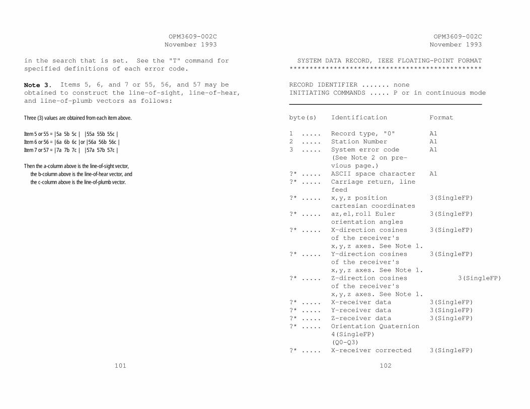
OPM3609-002C November 1993
101
in the search that is set. See the "T" command for specified definitions of each error code. Note 3. Items 5, 6, and 7 or 55, 56, and 57 may be obtained to construct the line-of-sight, line-of-hear, and line-of-plumb vectors as follows:
Three (3) values are obtained from each item above. Item 5 or 55 = | 5a 5b 5c | | 55a 55b 55c | Item 6 or 56 = | 6a 6b 6c | or | 56a 56b 56c | Item 7 or 57 = | 7a 7b 7c | | 57a 57b 57c | Then the a-column above is the line-of-sight vector, the b-column above is the line-of-hear vector, and the c-column above is the line-of-plumb vector.
OPM3609-002C November 1993
102
SYSTEM DATA RECORD, IEEE FLOATING-POINT FORMAT ************************************************ RECORD IDENTIFIER ....... none INITIATING COMMANDS ..... P or in continuous mode byte(s) Identification Format 1 ..... Record type, "0" A1 2 ..... Station Number A1 3 ..... System error code A1 (See Note 2 on pre- vious page.) ?* ..... ASCII space character A1 ?* ..... Carriage return, line feed ?* ..... x,y,z position 3(SingleFP) cartesian coordinates ?* ..... az,el,roll Euler 3(SingleFP) orientation angles ?* ..... X-direction cosines 3(SingleFP) of the receiver's x,y,z axes. See Note 1. ?* ..... Y-direction cosines 3(SingleFP) of the receiver's x,y,z axes. See Note 1. ?* ..... Z-direction cosines 3(SingleFP) of the receiver's x,y,z axes. See Note 1. ?* ..... X-receiver data 3(SingleFP) ?* ..... Y-receiver data 3(SingleFP) ?* ..... Z-receiver data 3(SingleFP) ?* ..... Orientation Quaternion 4(SingleFP) (Q0-Q3) ?* ..... X-receiver corrected 3(SingleFP)

OPM3609-002C November 1993
103
values ?* ..... Y-receiver corrected 3(SingleFP) values ?* ..... Z-receiver corrected 3(SingleFP) values ?* ..... Self Calibration Data 9(SingleFP) ************************************************ ?* The system data record contents are
specified by the user using the "O" command and may vary from configuration to configuration. Therefore, the specific location of a data item in the output record is not determined until the record contents are defined.
NOTE 1 Items 5, 6, and 7 or 55, 56, and 57 may be obtained to construct the line-of-sight, line-of-
hear, and line-of-plumb vectors as follows: Three (3) values are obtained from each item above. Item 5 or 55 = | 5a 5b 5c | | 55a 55b 55c | Item 6 or 56 = | 6a 6b 6c | or | 56a 56b 56c | Item 7 or 57 = | 7a 7b 7c | | 57a 57b 57c | Then the a-column above is the line-of-sight vector, the b-column above is the line-of-hear vector, and the c-column above is the line-of-plumb vector.
OPM3609-002C November 1993
104
SYSTEM DATA RECORD, 16-BIT BINARY FORMAT ************************************************ RECORD IDENTIFIER ....... none INITIATING COMMANDS ..... P or in continuous mode byte(s) Identification Format 1 ..... Record type, "0" A1 2 ..... Station Number A1 3 ..... Error code A1 ?* ..... x,y,z position 3(16BIT) cartesian coordinates ?* ..... az,el,roll Euler 3(16BIT) orientation angles ?* ..... Orientation Quaternion 4(16BIT) Values ?* ..... Any format from an ASCII or IEEE format may
also be included in this record. (See these formats on previous pages.) Care should be taken not to delete the usefulness of the sync bit discussed below.
************************************************ ?* The system data record contents are
specified by the user using the "O" command and may vary from configuration to configuration. Therefore, the specific location of a data item in the output record is not determined until the record contents are defined.
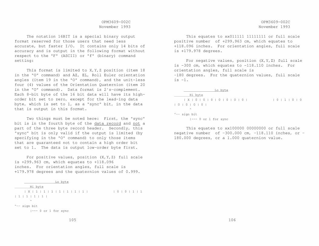
OPM3609-002C November 1993
105
The notation 16BIT is a special binary output format reserved for those users that need less accurate, but faster I/O. It contains only 14 bits of accuracy and is output in the following format without respect to the "F" (ASCII) or "f" (binary) command setting: This format is limited to X,Y,Z position (item 18 in the "O" command) and AZ, EL, Roll Euler orientation angles (item 19 in the "O" command), and the unit-less four (4) values of the Orientation Quaternion (item 20 in the "O" command). Data format is 2's-complement. Each 8-bit byte of the 16 bit data will have its high-order bit set to zero, except for the lead-ing data byte, which is set to 1, as a "sync" bit, in the data that is output in this format. Two things must be noted here: First, the "sync" bit is in the fourth byte of the data record and not a part of the three byte record header. Secondly, this "sync" bit is only valid if the output is limited (by specifying in the "O" command) to only those items that are guaranteed not to contain a high order bit set to 1. The data is output low-order byte first. For positive values, position (X,Y,Z) full scale is +299.963 cm, which equates to +118.096 inches. For orientation angles, full scale is +179.978 degrees and the quaternion values of 0.999. Lo byte
Hi byte
| X | 1 | 1 | 1 | 1 | 1 | 1 | 1 | | 0 | 0 | 1 | 1
| 1 | 1 | 1 | 1 |
^
^-- sign bit
|--- 0 or 1 for sync
OPM3609-002C November 1993
106
This equates to xx011111 11111111 or full scale positive number of +299.963 cm, which equates to +118.096 inches. For orientation angles, full scale is +179.978 degrees. For negative values, position (X,Y,Z) full scale is -300 cm, which equates to -118.110 inches. For orientation angles, full scale is -180 degrees. For the quaternion values, full scale is -1. Lo byte
Hi byte
| X | 0 | 0 | 0 | 0 | 0 | 0 | 0 | | 0 | 1 | 0 | 0
| 0 | 0 | 0 | 0 |
^
^-- sign bit
|--- 0 or 1 for sync
This equates to xx100000 00000000 or full scale negative number of -300.000 cm, -118.110 inches, or - 180.000 degrees, or a 1.000 quaternion value.

OPM3609-002C November 1993
107
OUTPUT FORMAT Description: Format refers to the method by which
data is coded. ASCII format means that the data is generally human readable, while binary is generally computer readable. The data format controls only the output format. All input to the system must be ASCII. Binary format output is in accordance with the format specified by ANSI/IEEE Std 754-1985 Specification for Binary Floating Point Arithmetic. The current data format may be retrieved from the STATUS RECORD. Refer to the "S" (System Status) command.
Default: The default output data format is ASCII. Commands: F, f
OPM3609-002C November 1993
108
ENABLE ASCII OUTPUT FORMAT ************************************************ Syntax: F Class: configuration Purpose: When this command is active all data
transmitted through the system serial or parallel port will be in ASCII format. Default is active.
Relatives: f ************************************************

OPM3609-002C November 1993
109
ENABLE BINARY OUTPUT FORMAT ************************************************ Syntax: f Class: standard, configuration Purpose: Sets the output data format to binary.
Subsequent data record items are output in accordance with the format specified by ANSI/IEEE Std 754-1985 Specification for Binary Floating Point Arithmetic. Default is ASCII formatted records.
Relatives: F ************************************************
OPM3609-002C November 1993
110
OUTPUT PORT SETTINGS Description: The system RS-232 BAUD rate, parity, and
number of bits per character may be established to specified values.
Default: Based on I/O switch settings. Commands: o

OPM3609-002C November 1993
111
SET OUTPUT PORT ************************************************ Syntax: orate,parity,bits,HHS<> Class: standard Purpose: Sets the output BAUD rate for RS-232 port
to a specified rate. The parameters are: rate may be specified as follows: 3 = 300, 12 = 1200, 24 = 2400, 48 = 4800, 96 = 9600, 192 = 19200, 384 = 38400, 576 = 57600, or 1152 = 115200 parity N = none, O = Odd, E = even bits 7 or 8 HHS Set to 1, enables use of hardware
handshake (RTS, CTS) Set to 0, disables use of hardware
handshake Note 1. The number of stop bits is always
one (1). Note 2. For seven (7) bits, parity may be
NONE, ODD, or EVEN. For eight (8) bits there is never a parity bit; i.e., NONE.
OPM3609-002C November 1993
112
Note 3. 8 data bits are required when using either the standard binary format or the 16 BIT format.
Default: Based on I/O switch settings. Relatives: none ************************************************

OPM3609-002C November 1993
113
OUTPUT TRANSMIT MODE Description: Transmit mode refers to whether the
system automatically transmits a data record when it is ready (CONTINUOUS), or the host must request each data record by sending a "P" command to the system (NON-CONTINUOUS). The current transmit mode may be retrieved from the status record. Refer to Section 6.0 for the format of the STATUS RECORD.
Default: NON-CONTINUOUS. Commands: C, P, c
OPM3609-002C November 1993
114
CONTINUOUS PRINT OUTPUT ************************************************ Syntax: C Class: configuration Purpose: This command enables the continuous print
output mode for the system serial port. Default is non-continuous.
Relatives: c, P ************************************************

OPM3609-002C November 1993
115
SINGLE RECORD TRANSMISSION ************************************************ Syntax: P Class: standard Purpose: When continuous print has been disabled,
request that a single data record be transmitted to the host computer. If more than one station is active, one record for each of the active stations will be transmitted.
Relatives: C, c ************************************************
OPM3609-002C November 1993
116
DISABLE CONTINUOUS PRINTING ************************************************ Syntax: c Class: configuration Purpose: Disable continuous output to the host
computer. Default value is active. Relatives: C, P ************************************************

OPM3609-002C November 1993
117
INPUT/OUTPUT UNITS Description: Input/Output Units is a reference to the
distance unit assumed by the system when interpreting input and generating output data. The current distance unit may be retrieved by the host from the status record. Refer to the S command in this section.
Default: Inches (absolute) Commands: U, u
OPM3609-002C November 1993
118
SET UNITS INCHES ************************************************ Syntax: U Class: standard, configuration Purpose: Sets the distance unit to inches.
Subsequent input and output lengths are interpreted as inches. System default is inches.
Relatives: u ************************************************

OPM3609-002C November 1993
119
METRIC CONVERSION UNITS ************************************************ Syntax: u Class: standard, configuration Purpose: Sets the distance units to centimeters.
Subsequent inputs and outputs are interpreted as centimeters. The system default is inches.
Relatives: U ************************************************
OPM3609-002C November 1993
120
OUTPUT START/STOP (XON/XOFF) Description: Output start/stop is a pseudo
implementation of the RS-232 XON/XOFF protocol. The commands start and stop the transmission of data from the RS-232 device.
Default: XON (Enabled) Commands: ^S, ^Q

OPM3609-002C November 1993
121
SUSPEND DATA TRANSMISSION ************************************************ Syntax: ^S Class: standard Purpose: Suspends data transmission to the host
device until a subsequent ^Q is received. If a previous ^S command has been issued, without an intervening ^Q, this command will have no effect.
Relatives: ^Q ************************************************
OPM3609-002C November 1993
122
RESUME DATA TRANSMISSION ************************************************ Syntax: ^Q Class: standard Purpose: Resumes data transmission to the host
device following suspension of transmission by a ^S command. If a previous ^Q command has been issued, without an intervening ^S, this command will have no effect.
Relatives: ^S ************************************************

OPM3609-002C November 1993
123
STATIONS Description: A station is a transmitter-receiver
pair. The four receivers paired with the one available transmitter are assigned station numbers one through four (1-4). Stations may be activated or deactivated. If a station is active, data records are transmitted for that station; otherwise, no data records for that station are transmitted. At least one station must always be active.
Default: Rcvr Select Switch determines the
available power-up active receivers. Commands: l
OPM3609-002C November 1993
124
ACTIVE STATION STATE ************************************************ Syntax: lstation,[state]<> Class: standard Purpose: Set the on/off station state. If the
optional parameter is missing, the system returns the current state for the specified station as an output record of type "l". The parameters are:
Station FASTRAK 1 to 4 depending on
configuration. state 0 = off 1 = on Relatives: none ************************************************

OPM3609-002C November 1993
125
ACTIVE STATION STATE ************************************************ RECORD IDENTIFIER ........ l INITIATING COMMAND ....... l byte(s) Identification Format 1 ..... Record type, "2" A1 2 ..... Station number A1 3 ..... Sub-record type "l" A1 4 ..... Station 1 = 1 if active, A1 else 0 5 ..... Station 2 = 1 if active, A1 else 0 6 ..... Station 3 = 1 if active, A1 else 0 7 ..... Station 4 = 1 if active, A1 else 0 8-9 ..... Carriage return, line feed ************************************************
OPM3609-002C November 1993
126
STATUS Description: Status refers to the capability to
determine information about the system that is not available from other commands.
Commands: S, T
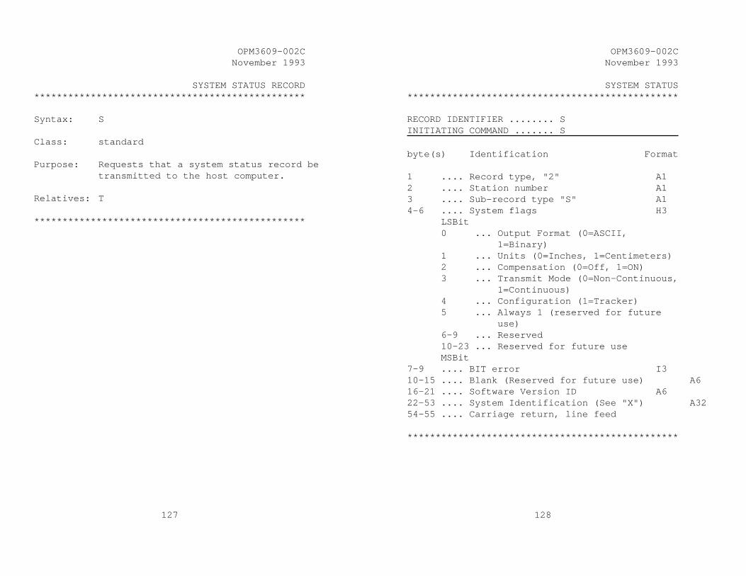
OPM3609-002C November 1993
127
SYSTEM STATUS RECORD ************************************************ Syntax: S Class: standard Purpose: Requests that a system status record be
transmitted to the host computer. Relatives: T ************************************************
OPM3609-002C November 1993
128
SYSTEM STATUS ************************************************ RECORD IDENTIFIER ........ S INITIATING COMMAND ....... S byte(s) Identification Format 1 .... Record type, "2" A1 2 .... Station number A1 3 .... Sub-record type "S" A1 4-6 .... System flags H3 LSBit 0 ... Output Format (0=ASCII, 1=Binary) 1 ... Units (0=Inches, 1=Centimeters) 2 ... Compensation (0=Off, 1=ON) 3 ... Transmit Mode (0=Non-Continuous, 1=Continuous) 4 ... Configuration (1=Tracker) 5 ... Always 1 (reserved for future use) 6-9 ... Reserved 10-23 ... Reserved for future use MSBit 7-9 .... BIT error I3 10-15 .... Blank (Reserved for future use) A6 16-21 .... Software Version ID A6 22-53 .... System Identification (See "X") A32 54-55 .... Carriage return, line feed ************************************************
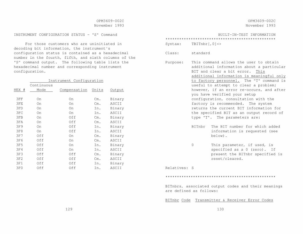
OPM3609-002C November 1993
129
INSTRUMENT CONFIGURATION STATUS - "S" Command For those customers who are uninitiated in decoding bit information, the instrument's configuration status is contained as a hexadecimal number in the fourth, fifth, and sixth columns of the "S" command output. The following table lists the hexadecimal number and corresponding instrument configuration. Instrument Configuration Continuous HEX # Mode Compensation Units Output 3FF On On Cm. Binary 3FE On On Cm. ASCII 3FD On On In. Binary 3FC On On In. ASCII 3FB On Off Cm. Binary 3FA On Off Cm. ASCII 3F9 On Off In. Binary 3F8 On Off In. ASCII 3F7 Off On Cm. Binary 3F6 Off On Cm. ASCII 3F5 Off On In. Binary 3F4 Off On In. ASCII 3F3 Off Off Cm. Binary 3F2 Off Off Cm. ASCII 3F1 Off Off In. Binary 3F0 Off Off In. ASCII
OPM3609-002C November 1993
130
BUILT-IN-TEST INFORMATION ************************************************ Syntax: TBITnbr[,0]<> Class: standard Purpose: This command allows the user to obtain
additional information about a particular BIT and clear a bit error. This additional information is meaningful only to factory personnel. The "T" command is useful to attempt to clear a problem; however, if an error re-occurs, and after you have verified your setup configuration, consultation with the factory is recommended. The system returns the current BIT information for the specified BIT as an output record of type "T". The parameters are:
BITnbr The BIT number for which added
information is requested (see below).
0 This parameter, if used, is
specified as a 0 (zero). If present the BITnbr specified is reset/cleared.
Relatives: S ************************************************ BITnbrs, associated output codes and their meanings are defined as follows: BITnbr Code Transmitter & Receiver Error Codes

OPM3609-002C November 1993
131
65 A X Driver Linearity 66 B Y Driver Linearity 67 C Z Driver Linearity 68 D x Gain Linearity 69 E y Gain Linearity 70 F z Gain Linearity 71 G X Slope of Driver X Linearity Line 72 H Y Slope of Driver Y Linearity Line 73 I Z Slope of Driver Z Linearity Line 74 J X Slope of Coil / Receiver X Linearity 75 K Y Slope of Coil / Receiver Y Linearity 76 L Z Slope of Coil / Receiver Z Linearity 77-83 Not Used (Reserved for future use) 84 T Receiver PROM Error 85 U Transmitter PROM Error 86 V Receiver PROM Circuit Error 87 W Transmitter PROM Circuit Error 88 X Driver Characterization Validity 89 Y Receiver Characterization Validity 90 Z Receiver Coil Validity BITnbr Code Self Calibration Error Codes 97 a X Driver Limits Self-Calibration 98 b Y Driver Limits Self-Calibration 99 c Z Driver Limits Self-Calibration 100 d x Gain Limits Self-Calibration 101 e y Gain Limits Self-Calibration 102 f z Gain Limits Self-Calibration 103 g Coil Limits Self-Calibration 104 h Not Used in FASTRAK BITnbr Code Signal Matrix Error Codes
OPM3609-002C November 1993
132
105 i Not Used in FASTRAK 106 j A Signal Saturation 107 k A Low Signal 108 l A Maximum Signal Element Zero BITnbr Code EEPROM Error Codes 109 m EEPROM Validity Checksum Error or Data
Validity Discrepancy 110 n Reserved for Future Use 111 o Reserved for Future Use 112 p Reserved for Future Use 113 q Reserved for Future Use 114 r Reserved for Future Use BITnbr Code Soft Error Codes 115 s Unit Normal Position Vector Reset (P/R-
Norm) BITnbr Code Miscellaneous Error Codes 116 t Compensation Structure Errors. Array Size Not In Specification Limits. 117 u Compensation Point Not Within Mapped
Bounds. 118 v No CRT Sync Signal Available 119 w Write Error on Configuration EEPROM. 120 x Receiver Out of Motion Box. 121 y Euler Angles Outside Allowed Angular
Envelope. 122 z Unused, Reserved.

OPM3609-002C November 1993
133
BIT INFORMATION ************************************************ RECORD IDENTIFIER ........ T INITIATING COMMAND ....... T byte(s) Identification Format 1 ... Record type, "2" A1 2 ... Blank A1 3 ... Sub-record type "T" A1 4-6 ... BIT number I3 7-?? ... BIT information A?? (Factory meaningful only) ??-?? ... Carriage return, line feed ************************************************
OPM3609-002C November 1993
134
STYLUS Description: Stylus refers to the tip definition and
button operation functions of the Stylus.
Commands: N, e

OPM3609-002C November 1993
135
DEFINE TIP OFFSETS ************************************************ Syntax: Nstation,[xoff,yoff,zoff]<> Class: Standard Purpose: This command allows the user to override
the factory defaults for the offsets of the receiver from the tip of a stylus. If the optional parameters are missing, the system returns the current tip offset for the specified station as an output record of type "N". The parameters are:
station = 1 for stylus xoff x-direction tip offset yoff y-direction tip offset zoff z-direction tip offset Default: This command can only override the factory
default during the current operational session. Factory defaults are read on power-up.
Relatives: none ************************************************
OPM3609-002C November 1993
136
DEFINE STYLUS BUTTON FUNCTION ************************************************ Syntax: e[station],fbutton<> Class: Configuration Purpose: This command allows the host to put a
FASTRAK stylus into different output modes. The command parameters are defined as:
station the number of a station.
Inclusion or omission of this parameter has NO effect on handling of this command. The parameter is retained for compatibility with other commands and products.
fbutton defines the function of the
stylus button. An entry of fbutton = 0 defines
the output interaction as "mouse mode." The pushing of the stylus switch has no change on system output except that if the user has defined (by use of the "0" command) an output with item 16 (switch status), then the status of the switch is reported in the output record. In this case a 1 is reported in the output record when the switch is pressed and a 0 when it is not pressed.

OPM3609-002C November 1993
137
An entry of fbutton = 1 defines a pseudo "point" or "track" mode inter-action with the switch. In non-continuous mode of output, pressing the stylus switch has the same effect as sending a "P" command to the system (Point mode). In continuous output mode, pressing the stylus switch serves as a toggle for continuous output; i.e., the first time the switch is pressed, turns off output and the next pressing turns on continuous output (Track mode).
Default: System default is fbutton = 1 (point and
track mode stylus interaction) Relatives: None ************************************************
OPM3609-002C November 1993
138
6.10 Command Error Command errors are defined as follows: COMMAND ERROR ************************************************ RECORD IDENTIFIER ........ * INITIATING COMMAND ....... all invalid commands byte(s) Identification Format 1 ... Record Type, "2" A1 2 ... Blank A1 3 ... Sub-record type "E" A1 4-10 ... "*ERROR*" 11-?? ... Erroroneous command as it was input ??-+11... "*ERROR* EC " ??-?? ... Error code from follow- ing list: -1 Required field missing -2 Required numeric is non-numeric -3 Value is outside required range -4 Specified frequency not hardware configured -5 Internal buffer limits exceeded -99 Undefined input - cannot identify command ??-+3 ... "*PS" (position) ??-?? ... Character position in the input record -
note numbering starts 0,1,2... ??-+3 ... "*FL" (field)

OPM3609-002C November 1993
139
??-?? ... Field number causing the error - note numbering of the field is 0,1,2... and starts at '0' following the command identifier.
??-+3 ... "*ST" (station) ??-?? ... Number of the affected system station less
1; i.e., this value ranges from 0-3, stations are numbered in commands as 1-4.
************************************************
OPM3609-002C November 1993
140
6.11 Default Operation with a Stylus or 3BALL As noted in Section 5, the Stylus and 3BALL may only be operated in Port #1 as this port is the only one that will read a switch status. Operation of the switch on either the Stylus or 3BALL will cause the following actions as a function of the various FASTRAK commands and modes. No other actions are possible. In NON-continuous output mode pressing the switch defines to the FASTRAK instrument a 'P' command, and all operations are as documented for issuing an RS-232 or IEEE-488 'P' command. Issuing a 'P' command via RS-232 or IEEE-488 still performs as documented. When a 'C' command is entered via RS-232 or IEEE-488 to enable continuous mode, the instrument immediately responds with output as defined in the manual; however, when the Stylus/3BALL switch is pressed, output is interrupted (but this cycle is completed; i.e., all currently configured stations complete output for this cycle). The Stylus/3BALL switch then serves as a toggle for instrument output from then on until an RS-232 or IEEE-488 'c' command is issued. Each toggle will initiate or terminate a continuous stream of output that begins with station one (1) and terminates (by a subsequent switch pressing) with output for the last station in the cycle list. Note that all output begins with the FIRST station (in the sequence 1, 2, 3, 4) that is configured ON and ends with the LAST station in the sequence list that is configured ON. Configured ON requires both a proper selection switch at power-on and NOT a current use of the "1" command, to change the receiver's state to OFF.

OPM3609-002C November 1993
141
Increment functions as defined in this document. That is, if any receiver does NOT move, since its last cycle, by an amount equal to or greater than its defined increment, output is skipped for the receiver when the above actions cause an output. A switch cycle takes 40 system cycles. At 8.33 msec per cycle, the switch is responsive at a speed of 333 msec or about 1/3 second. In other words, if the switch is held down while the system is in NON-continuous mode, an output cycle is generated as if a 'P' command in entered at the rate of 3/second. If the switch is pressed twice within the 333 msec window, the second pressing is ignored. See the Define Stylus Button function ("e" Command) for other options and operational information.
OPM3609-002C November 1993
142
7.0 LIMITED WARRANTY AND LIMITATION OF LIABILITY 7.1 PI warrants that the Systems shall be free from defects in material and workmanship for a period of one year from the date ownership of the System passed from PI to Buyer. PI shall, upon notification within the warranty period, correct such defects by repair or replacement with a like serviceable item at PI's option. This warranty shall be considered void if the System is operated other than in accordance with the instructions in PI's User Manual or is damaged by accident or mishandling. Parts or material which are clearly expendable or subject to normal wear beyond usefulness within the warranty period such as lamps, fuses, etc., are not covered by this warranty. 7.2 In the event any System or portion thereof is defective, Buyer shall, within the warranty period, notify PI in writing of the nature of the defect, remove the defective parts and, at the direction of PI, ship such parts to PI. Upon determination by PI that the parts or Systems are defective and covered by the warranty set forth above, PI, at its option shall repair or replace the same without cost to Buyer. Buyer shall pay all charges for transportation and delivery costs to PI's factory for defective parts where directed to be sent to PI, and PI shall pay for transportation costs to Buyer's facility only for warranty replacement parts and Systems. Removed parts covered by claims under this warranty shall become the property of PI. 7.3

OPM3609-002C November 1993
143
In the event that allegedly defective parts are found not to be defective, or not covered by warranty, Buyer agrees that PI may invoice Buyer for all reasonable expenses incurred in inspect-ing, testing, repairing and returning the Systems and that Buyer will pay such costs on being invoiced therefor. Buyer shall bear the risk of loss or damage during transit in all cases. 7.4 Any repaired or replaced part or System shall be warranted for the remaining period of the original warranty or thirty (30) days, whichever is longer. 7.5 Warranties shall not apply to any Systems which have been: (a) repaired or altered other than by PI, except
when so authorized in writing by PI. (b) used in an unauthorized or improper manner,
or without following normal operating procedures; or
(c) improperly maintained and where such activities in PI's sole judgement, have adversely affected the Systems. Neither shall warranties apply in the case of damage through accidents or acts of nature such as flood, earthquake, lightning, tornado, typhoon, power surge or failure, environmental extremes or other external causes.
7.6 PI DOES NOT WARRANT AND SPECIFICALLY DISCLAIMS THE
OPM3609-002C November 1993
144
WARRANTY OF MERCHANTABILITY OF THE PRODUCTS OR THE WARRANTY OF FITNESS OF THE PRODUCTS FOR ANY PARTICULAR PURPOSE. PI MAKES NO WARRANTIES, EXPRESS OR IMPLIED, EXCEPT OF TITLE AND AGAINST PATENT INFRINGEMENT, OTHER THAN THOSE SPECIFICALLY SET FORTH HEREIN. 7.7 IN NO EVENT SHALL PI BE LIABLE UNDER ANY CIRCUMSTANCES FOR SPECIAL INCIDENTAL OR CONSEQUENTIAL DAMAGES, INCLUDING, BUT NOT LIMITED TO LOSS OF PROFITS OR REVENUE. WITHOUT LIMITING THE FOREGOING PI'S MAXIMUM LIABILITY FOR DAMAGES FOR ANY CAUSE WHATSOEVER, EXCLUSIVE OF CLAIMS FOR PATENT INFRINGEMENT AND REGARDLESS OF THE FORM OF THE ACTION (INCLUDING BUT NOT LIMITED TO CONTRACT NEGLIGENCE OR STRICT LIABILITY) SHALL BE LIMITED TO BUYER'S ACTUAL DIRECT DAMAGES, NOT TO EXCEED THE PRICE OF THE GOODS UPON WHICH SUCH LIABILITY IS BASED.

OPM3609-002C November 1993
145
8.0 INDEMNITY AGAINST PATENT INFRINGEMENT PI shall have the right at its own expense, to defend or at its option to settle, any claim, suit or proceeding brought against Buyer on the issue of infringement of any United States patent by any product, or any part thereof, supplied by PI to Buyer under this Agreement. PI shall pay, subject to the limitations hereinafter set forth in this paragraph, any final judgment entered against Buyer on such issue in any such suit or proceeding defended by PI. PI at its sole option shall be relieved of the foregoing obligations unless Buyer notified PI promptly in writing of any such claim, suit or proceedings, and at PI's expense, gave PI proper and full information and assistance to settle and/or defend any such claim, suit or proceeding. If the product, or any part thereof, furnished by PI to Buyer becomes, or in the opinion of PI may become, the subject of any claim, suit or proceeding for infringement of any United States patent, or in the event of an adjudication that such product or part infringes any United States patent, or if the use, lease or sale of such product or part is enjoined, PI may, at its option and its expense: (a) procure for Buyer the right under such patent to use, lease or sell, as appropriate, such product or part, or (b) replace such product or part, or (c) modify such product, or part, or (d) remove such product or part and refund the aggregate payments and transportation costs paid therefore by the Buyer less a reasonable sum for use, damage and obsolescence. PI shall have no liability for any infringement arising from: (i) the combination of such product or part with any other product or part whether or not furnished to Buyer by PI, or (ii) the modification of such product or part unless such modification was made by PI, or (iii) the use of such product or part in practicing any process, or (iv) the
OPM3609-002C November 1993
146
furnishing to Buyer of any information, data, service or application assistance. Buyer shall hold PI harmless against any expense, judgment or loss for infringement of any United States patents or trademarks which results from PI's compliance with Buyer's designs, specifications or instructions. PI shall not be liable for any costs or expense incurred without PI's written authorization and in no event shall PI's total liability to Buyer under, or as a result of compliance with, the provisions of this paragraph exceed the aggregate sum paid to PI by Buyer for the allegedly infringing product or part, exclusive of any refund under option (4) above. The foregoing states the entire liability of PI, and the exclusive remedy of Buyer, with respect to any actual or alleged patent infringement by such product or part.

OPM3609-002C November 1993
147
9.0 CUSTOMER SERVICE If you encounter any problems with your FASTRAK instrument, help is just a telephone call away. Call 802/655-3159 and ask for Customer Service. For the most part, our Customer Service engineers can handle your problems over the telephone and get you back into the fast lane right away. If the problem requires repair of your instrument, the Customer Service engineer will issue you a Return Merchandise Authorization (RMA) number. It is a good idea to keep the original shipping container for your FASTRAK instrument in the event that the instrument may require repair. Please do not return any instrument without an RMA number as it will not be accepted. If your instrument is still under warranty, Polhemus will repair it free of charge according to the provisions of the warranty as stated in Section 8 of this document. The proper return address is: Polhemus Incorporated 1 Hercules Drive P.O. Box 560 Colchester, Vermont 05446 Telephone (voice): (802) 655-3159 Telephone (FAX): (802) 655-1439
OPM3609-002C November 1993
148
INDEX Cmnd. Ltr FASTRAK Title Page A Alignment Reference Frame 46 B Boresight 50 b Unboresight 54 C Continuous Print Output 118 c Disable Continuous Printing 120 D Enable Fixed Metal Compensation 56 d Disable Fixed Metal Compensation 57 e Define Stylus Button Function 141 F Enable ASCII Output Format 112 f Enable Binary Formatted Output 113 G Boresight Reference Angles 52 H Hemisphere of Operation 89 I Define Increment 93 l Active Station State 128 O Output Data List 97 o Set Output Port 115 N Define Tip Offsets 140 P Single Record Transmission 115 Q Angular Operational Envelope 81 R Reset Alignment Reference Frame 49 r Transmitter Mounting Frame 58 S System Status 131 T Built-In-Test Information 134 U Set Unit Inches 122 u Metric Conversion Units 123 V Position Operational Envelope 84 v Attitude Filter Parameters 64 W Reset System to Defaults 76 X Configuration Control Data 77 x Position Filter Parameters 65 y Set Synchronization Mode 70

OPM3609-002C November 1993
149
INDEX Cmnd. Ltr FASTRAK Title Page ^K Save Operational Configuration 74 ^Q Resume Data Transmission 126 ^S Suspend Data Transmission 125 ^Y Re-initialize System 75
OPM3609-002C November 1993
150
GLOSSARY Alignment Frame The reference frame in which the position and orientation of the receiver is measured. The default alignment frame is the transmitter frame. Attitude Matrix A three-by-three matrix containing the direction cosines of the receiver's x axis in column one, the direction cosines of the receiver's y axis in column two, and the direction cosines of the receiver's z axis in column three. The order of the 3SPACE Euler angle rotation sequence is azimuth, elevation, and roll. CA*CE | CA*SE*SR-SA*CR | CA*SE*CR+SA*SR | | SA*CE | CA*CR+SA*SE*SR | SA*SE*CR-CA*SR | | -SE | CE*SR | CE*CR | | | | X direction | Y direction | Z direction cosines | cosines | cosines where: SA = Sin (azimuth), CA = Cos (azimuth) SE = Sin (elevation), CE = Cos (elevation) SR = Sin (roll), CR = Cos (roll)

OPM3609-002C November 1993
151
Azimuth (See Orientation Angles) Boresight Any procedure that rotates the receiver frame so as to precisely align the receiver to the designated reference frame. In a 3SPACE system context, the term usually refers to the system software routine that, on command, performs a coordinate rotation which effectively aligns the receiver frame to a predefined boresight reference orientation. Note that the boresight routine accomplishes the boresight orientation of the receiver regardless of the receiver's physical orientation at the instant of boresight initiation. So, for applications that require the orientation tracking of the body (or body member) to which the receiver is attached, a prerequisite to initiating the boresight function is a physical orientation of the body to be tracked to the boresight reference orientation. Compensation Data A set of invariable data that allows the 3SPACE to compensate for fixed distortions of the magnetic field due to the surrounding environment. The compensation data generally results from an application-specific distortion mapping procedure.
OPM3609-002C November 1993
152
Direction Cosines The cosines of the angles between the receiver's x, y, z axes and the X, Y, Z axes of the measurement reference (alignment) frame. EEPROM Electronically Erasable Programmable Read Only Memory. Memory that can be altered by the 3SPACE, but is not lost when the power is OFF. User default data is stored here, as well as the system identification data. Elevation (See Orientation Angles) Factory Defaults The values assigned to certain system variables by the factory. Stored in PROM, they are used to reinitialize the variables if EEPROM is lost. Format The interchange coding used to present data. The 3SPACE outputs either ASCII or BINARY data, but accepts only ASCII inputs from the host. Hemisphere

OPM3609-002C November 1993
153
Because of the inversion symmetry of the magnetic fields generated by the transmitter, there are two possible mathematical solutions for the X, Y, Z, position coordinates for each set of receiver data processed, and the 3SPACE is unable to determine which solution is the correct one without additional information. Therefore, only half of the total spatial sphere surrounding the transmitter can be utilized at any one time for unambiguous position measurement. The selected hemisphere is referred to as the "current hemisphere." It is defined by an LOS (line-of-sight) vector from the transmitter through a point at the zenith of the hemisphere, and is specified by the direction cosines of the chosen LOS vector. The orientation coordinates do not have a two-solution spherical ambiguity and are therefore valid throughout the operating sphere centered at the transmitter. Host Any device capable of supporting an RS-232C interface or the 3SPACE IEEE-488 parallel interface and capable of bi-directional data transmission. Devices may range from a dumb terminal to a mainframe computer. Increment The minimum movement necessary to cause the 3SPACE to transmit a record to the host.
OPM3609-002C November 1993
154
Orientation Angles The azimuth, elevation, and roll angles that define the current orientation of the receiver coordinate frame with respect to the designated reference frame. The Euler angle coordinates that are output by the 3SPACE as one measure of receiver orientation are graphically defined in Figure 11. In Figure 11, the x,y,z and X, Y, Z tri-axis arrays represent independent, three-dimensional orthogonal coordinate frames. The x,y,z triad represents the receiver frame in its current orientation state. The X,Y,Z triad represents the reference frame against which the relative orientation of the receiver frame is measured. By definition then, the X,Y,Z frame also represents the zero-orientation reference state of the receiver frame. The 3SPACE Euler angles, azimuth, elevation and roll, are designated ø, è, and ö in Figure 11. These angles represent an azimuth-primary sequence of frame rotations that define the current orientation of the receiver with respect to its zero-orientation state. The defining rotation sequence is an azimuth rotation followed by an elevation rotation followed by a roll rotation. The azimuth angle ø is defined in Figure 11 as a rotation of the X and Y reference axes about the Z reference axis. Note that the transition axes labelled X' and Y' represent the orientation of the X and Y axes after the azimuth rotation. The elevation angle è is defined as a rotation of the Z reference axis and the X' transition axis about the

OPM3609-002C November 1993
155
Y' transition axis. Note that the transition axis labelled Z' represents the orientation of the Z reference axis after the elevation rotation. Note also that the current x axis of the current sensor frame represents the orientation of the X' transition axis after the elevation rotation. Lastly, the roll angle ö is defined as a rotation of the Y' and Z' transition axes about the x axis of the sensor frame. Note that the y and z axes of the current sensor frame represent the orientation of the Y' and Z' transition axes after the roll rotation. Note also that in the example of Figure 11, the azimuth, elevation and roll rotations are positive, negative and positive respectively. Output List A list of the data items included in a data record.
OPM3609-002C November 1993
156
X, Y, Z = Alignment (Reference) Frame X, Y, Z = Rotated Stylus or Receiver Coordinate Frame Ø = Azimuth È = Elevation ö = Roll Figure 11. The 3SPACE Euler Angles.

OPM3609-002C November 1993
157
Quaternion A four-parameter quantity representing a vector and a scalar. The quaternion q = q0 + i q1 + j q2 + k q3 can be used to represent the receiver's orientation without the need for trigonometric functions. The attitude matrix output from the 3SPACE can be equivalently represented by the following matrix using quaternions:
X Directional Y Directional Z Directional Cosines Cosines Cosines Receiver The receiver measures the low-frequency magnetic field generated by the transmitter. The receiver is used to track both the position and orientation of the object to which it is attached, relative to the measurement reference frame. Roll (See Orientation Angles)
q + q - q - q )qq + qq2( )qq - qq2(
)qq - qq2( q - q + q - q )qq + qq2(
)qq + qq2( )qq - qq2( q - q - q + q
23
22
21
2023012031
103223
22
21
202103
2031302123
22
21
20
OPM3609-002C November 1993
158
Station The transmitter-receiver pair. Up to four receivers are permitted, yielding a possible four stations. Stylus A pencil-shaped housing for the receiver with an integral switch and used by the operator to indicate and/or select points to be digitized. System Identification Data (SID) Thirty-two characters of data (hardware serial number, etc.) stored in EEPROM containing information identifying the system. Transmitter The transmitter generates the low-frequency magnetic field measured by the receiver. The transmitter's X, Y, and Z axes are the default measurement reference frame. Units The unit of assumed distance. The 3SPACE allows either inches or centimeters.

OPM3609-002C November 1993
159
User Defaults The values assigned to certain system variables by the user. Stored in EEPROM, the system receives these variable values at power-up.
OPM3609-002C November 1993
A-1
APPENDIX A IEEE-488 Not all host computers are equipped with IEEE-488 I/O capability. If you decide that using the 488 is required for your application and are in need of acquiring specific hardware, etc. to make your host compatible, the following list is presented. This listing is of known suppliers of IEEE-488 interface boards, code, cables, etc. No endorsement is implied by inclusion on this list; nor does the exclusion have any negative implications. Black Box Corp. P.O. Box 12800 Pittsburgh, PA 15241 412/746-5530 Sales Capital Equipment Corp. 76 Blanchard Road Burlington, MA 01803 617/273-1818 John Fluke Mfg. Co., Inc. P.O. Box 9090 Everett, VA 98206 206/347-6100 Intelligent Interfaces, Inc. P.O. Box 1486 Stone Mountain, GA 30086-1486 404/381-9891 IOtech Inc.

OPM3609-002C November 1993
A-2
25971 Cannon Road Cleveland, OH 44146 216/439-4091 National Instruments Corporate Office 6504 Bridge Point Parkway Austin, TX 78730-5039 512/794-0100 Ziatech Corp. 3433 Roberto Court San Luis Obispo, CA 93401 805/541-0488 DY4 Systems Inc. 7 Concord Street, Suite 2 Nashua, NH 03060-2328 603/595-2400 DY4 Systems Inc. 1475 S. Bascom Avenue, Suite 202 Campbell, CA 95008 408/377-9822 Bit 3 8120 Penn Avenue South Minneapolis, MN 55431-1393 612/881-6955
OPM3609-002C November 1993
A-3
Using the IEEE-488 The 488 should be selected by the dip switch along with the 488 address. The general protocol for sending data to the FASTRAK system is to address the device to listen and send the data. It need not be terminated with an EOI because, as with the RS-232, commands are terminated with a carriage return or nothing at all, depending on the command. When the FASTRAK outputs data, the SRQ line is set active. The controller should poll this line for activity, and then proceed with a serial poll after detecting activity. The poll will clear the SRQ. The system should be addressed to talk and the data is then transmitted. The last byte output from the system is transmitted with EOI active. If operating in continuous mode, only one record of data is in the output buffer. If the system attempts to update the buffer and data measured during the last cycle is still present, the update will not occur. Therefore, to have the lowest latency, the data must be transferred in less than the cycle time of 8.3 milliseconds. The system communicates at about 100 KB/ second maximum rate. The system can sustain this rate for 0.5 milliseconds after SRQ is activated with no slowing of the 8.3 milli-seconds system update rate. If transmission lasts longer and is at a rate higher than 50 KB/second, the system will only be servicing the 488 and the update rate of the system will suffer. This allows for about a 50 byte output record before system update rate is affected.

OPM3609-002C November 1993
A-4
If the 488 is operated at a rate slower than 50 KB/second, then the system update rate may also decrease depending upon the length of the data output record.
OPM3609-002C November 1993
i
TABLE OF CONTENTS SOFTWARE COMMAND STRUCTURE COMPARISON........ vi 1.0 Same................................. vi 2.0 Modified.............................vii 3.0 Deleted.............................viii 4.0 New.................................viii GETTING STARTED...............................ix 1.0 INTRODUCTION............................. 1 2.0 HARDWARE................................. 1 Standard Items........................... 1 Optional Items........................... 2 3.0 OVERVIEW................................. 2 4.0 SPECIFICATION............................ 4 Position Coverage........................ 4 Angular Coverage......................... 4 Static Accuracy.......................... 4 Resolution............................... 4 Latency.................................. 4 Output................................... 4 Carrier Frequency........................ 5 Interfaces............................... 5 Operating Environment.................... 6 Operating Temperature.................... 6 Physical Characteristics................. 6 3BALL.................................... 7 Power Requirements....................... 7

OPM3609-002C November 1993
ii
5.0 COMPONENT DESCRIPTION.................... 8 5.1 SEU................................. 8 5.2 Receiver Inputs/Selector Switch..... 8 5.3 Transmitter Output.................. 11 5.4 Power Indicator..................... 11 5.5 I/O Select Switch................... 11 5.6 External Sync I/O................... 14 5.7 IEEE-488 I/O........................ 16 5.8 Frequency Select Module............. 16 5.9 RS-232 I/O.......................... 17 5.10 Optional RS-422 I/O................. 18 5.11 Video Sync Input.................... 18 5.12 Power Input Receptacle.............. 19 5.13 Cooling Fan ........................ 19 5.14 Transmitter......................... 19 5.15 Receiver(s)......................... 21 5.16 Stylus.............................. 21 5.17 3BALL............................... 21 5.18 Video Sync Detector................. 25 5.19 Diskette............................ 25 6.0 INSTRUMENT OPERATION..................... 27 6.1 I/O Considerations.................. 27 6.2 Setup............................... 29 6.3 Power-Up............................ 29 6.4 Output Considerations............... 30 6.5 Synchronization and Multiple Systems............................. 31 6.6 System Commands and Outputs......... 35 6.7 Command Format Notation and Convention.......................... 36 6.8 Output Record Format Notation and Conventions
.................................... 39 6.9 Command/Output Listing.............. 42 ALIGNMENT........................... 42 ALIGNMENT REFERENCE FRAME........... 47
OPM3609-002C November 1993
iii
RESET ALIGNMENT REFERENCE FRAME..... 50 BORESIGHT........................... 51 BORESIGHT........................... 52 BORESIGHT REFERENCE ANGLES.......... 53 UNBORESIGHT......................... 55 COMPENSATION........................ 56 ENABLE FIXED METAL COMPENSATION..... 57 DISABLE FIXED METAL COMPENSATION.... 58 TRANSMITTER MOUNTING FRAME.......... 59 ATTITUDE FILTER PARAMETERS.......... 61 POSITION FILTER PARAMETERS.......... 66 SET SYNCHRONIZATION MODE............ 71 EEPROM.............................. 73 SAVE OPERATIONAL CONFIGURATION...... 75 REINITIALIZE SYSTEM................. 76 RESET SYSTEM TO DEFAULTS............ 77 CONFIGURATION CONTROL DATA.......... 78 ENVELOPE............................ 80 ANGULAR OPERATIONAL ENVELOPE........ 82 POSITION OPERATIONAL ENVELOPE....... 85 HEMISPHERE.......................... 88 HEMISPHERE OF OPERATION............. 90 INCREMENT........................... 93 DEFINE INCREMENT.................... 94 SYSTEM OUTPUT DEFINITION............ 96 OUTPUT LIST......................... 97 OUTPUT DATA LIST.................... 98 OUTPUT ITEM LIST....................102 SYSTEM DATA RECORD, ASCII FORMAT....103 SYSTEM DATA RECORD, IEEE FLOATING-POINT FORMAT.............107 SYSTEM DATA RECORD, 16-BIT BINARY FORMAT.....................109 OUTPUT FORMAT.......................112 ENABLE ASCII OUTPUT FORMAT..........113 ENABLE BINARY OUTPUT FORMAT.........114 OUTPUT PORT SETTINGS................115 SET OUTPUT PORT.....................116

OPM3609-002C November 1993
iv
OUTPUT TRANSMIT MODE................118 CONTINUOUS PRINT OUTPUT.............119 SINGLE RECORD TRANSMISSION..........120 DISABLE CONTINUOUS PRINTING.........121 INPUT/OUTPUT UNITS..................122 SET UNITS INCHES....................123 METRIC CONVERSION UNITS.............124 OUTPUT START/STOP (XON/XOFF)........125 SUSPEND DATA TRANSMISSION...........126 RESUME DATA TRANSMISSION............127 STATIONS............................128 ACTIVE STATION STATE................129 STATUS..............................131 SYSTEM STATUS RECORD................132 INSTRUMENT CONFIGURATION STATUS.....134 BUILT-IN-TEST INFORMATION...........135 STYLUS..............................140 DEFINE TIP OFFSETS..................141 DEFINE STYLUS BUTTON FUNCTION.......142 6.10 Command Error.......................144 6.11 Default Operation with a Stylus or 3BALL.....................146 7.0 LIMITED WARRANTY AND LIMITATION OF LIABILITY 148 8.0 INDEMNITY AGAINST PATENT INFRINGEMENT....151 9.0 CUSTOMER SERVICE.........................153 INDEX........................................154 GLOSSARY.....................................156
OPM3609-002C November 1993
v
LIST OF FIGURES Figure 1. FASTRAK........................... 9 Figure 2. FASTRAK SEU....................... 10 Figure 3. FASTRAK Controls/Connections (Front & Rear)................ 15 Figure 4. Transmitter....................... 20 Figure 5. Receiver.......................... 22 Figure 6. Stylus............................ 23 Figure 7. 3BALL............................. 24 Figure 8. System Alignment.................. 45 Figure 9. System Envelope................... 81 Figure 10. System Hemisphere................. 89 Figure 11. The 3SPACE Euler Angles...........162