Fasteners Bolts, Nuts and Screws A hardware device that mechanically joins or affixes two or more...
51
Fasteners Bolts, Nuts and Screws A hardware device that mechanically joins or affixes two or more objects together.
-
Upload
noemi-alfred -
Category
Documents
-
view
229 -
download
1
Transcript of Fasteners Bolts, Nuts and Screws A hardware device that mechanically joins or affixes two or more...

FastenersBolts, Nuts and Screws
A hardware device that mechanically joins or affixes two or more objects together.

A lay person might consider threaded fasteners to be the most mundane and uninteresting of all machine elements. Looking deeper, the engineer finds that these seemingly simple components exist in amazing variety, and with design details representing remarkable ingenuity. The economic implications of fastener design (both threaded and non-threaded, as rivets) are tremendous. For example, the airframe of a large jet aircraft has approximately 2.4 million fasteners costing about $750,000. Fundamentals of Machine Component Design, Robert Juvinall, 1983
On average, a vehicle has more than 1,200 threaded fastener joints. That is 1,200 opportunities for joints to fail the customer. Joints may fail for many reasons, including loosening, vibrating, and leaking. Poor threaded fastener joint design is a major contributor to warranty costs at Ford Motor Company.
For all vehicles built from 1999 to 2003, on the average, fastener-related issues accounted for more than 16% of repairs and more than 8% of the warranty cost per unit. Not only does poor joint design increase warranty costs, but it can also result in:
• Overdesign that increases vehicle cost and weight
• Ergonomic issues in the assembly plant
• Unachievable process capability
• High repair costs
• Program delays
Ford Fastener and Joint Design HANDBOOK

Bolt or Screw?
There is no universally accepted distinction between a screw and a bolt. The Machinery's Handbook describes the distinction as follows:
A bolt is an externally threaded fastener designed for insertion through holes in assembled parts, and is normally intended to be tightened or released by torqueing a nut. An externally threaded fastener which is prevented from being turned during assembly and which can be tightened or released only by torqueing a nut is a bolt. (Example: round head bolts, track bolts, plow bolts.)
A screw is an externally threaded fastener capable of being inserted into holes in assembled parts, of mating with a preformed internal thread or forming its own thread, and of being tightened or released by torqueing the head.
An externally threaded fastener that has thread form which prohibits assembly with a nut having a straight thread of multiple pitch length is a screw. (Example: wood screws, tapping screws.)

Bolt or Screw?an alternative definition
Bolts have been defined as headed fasteners having external threads that meet an exacting, uniform bolt thread specification (such as M, MJ, UN, UNR, and UNJ) such that they can accept a non-tapered nut. Screws are then defined as headed, externally threaded fasteners that do not meet the above definition of bolts. These definitions of screw and bolt eliminate the ambiguity of the Machinery's handbook distinction. And it is for that reason, perhaps, that some people favor them. However, they are neither compliant with common usage of the two words nor are they compliant with formal specifications.

Thread Standards
The Unified Thread Standard (UTS) defines a standard thread form and series—along with allowances, tolerances, and designations—for screw threads commonly used in the United States and Canada. It has the same 60° profile as the ISO metric screw thread used in the rest of the world, but the characteristic dimensions of each UTS thread (outer diameter and pitch) were chosen as an inch fraction rather than a round millimeter value.
ISO (Metric, International Standards Organization) The ISO metric screw threads are the world-wide most commonly used type of general-purpose screw thread. They were one of the first international standards agreed when the International Organization for Standardization was set up in 1947
NOTE: The two systems are not interchangeable!

UTS (English) Bolt Terminology
Example:
¼ - 20 x 1 1/4 SHCS
Means
‘¼’ thread major diameter in inches
‘20’ threads per inch
‘1 ¼’ length of thread plus shank
‘SHCS’ socket head cap screw

UTS (English) Bolt Terminology
A. FULL DIAMETER SHANK: Equal to major diameter of thread. Produced by cut thread or by roll thread on extruded blank. Characteristic of machine bolts and cap screws. B. UNDERSIZED SHANK: Equal approximately to pitch diameter of thread. Produced by roll threading a non-extruded blank. Characteristic of machine screws.C. PITCH: The distance from a point on the screw thread to a corresponding point on the next thread measured parallel to the axis. D. PITCH DIAMETER: The simple, effective diameter of screw thread. Approximately half way between the major and minor diameters.E. MAJOR DIAMETER: The largest diameter of a screw thread. F. MINOR DIAMETER: The smallest diameter of a screw thread. LEAD: The distance a screw thread advances axially in one turn.

UTS (English) Bolt TerminologyCUT THREAD: Threads are cut or chased; the unthreaded portion of shank will be equal to major diameter of thread.ROLLED THREAD: Threads are cold formed by squeezing the blank between reciprocating serrated dies. This acts to increase the major diameter of the thread over and above the diameter of unthreaded shank (if any), unless an extruded blank is used.
Classes of thread are distinguished from each other by the amounts of tolerance and allowance specified. External threads or bolts are designated with the suffix "A"; internal or nut threads with "B".CLASSES 1A and 1B: For work of rough commercial quality where loose fit for spin-on-assembly is desirable. CLASSES 2A and 2B: The recognized standard for normal production of the great bulk of commercial bolts, nuts and screwsCLASSES 3A and 3B: Used where a closed fit between mating parts for high quality work is required.CLASS 4: A theoretical rather than practical class, now obsolete. CLASS 5: For a wrench fit. Used principally for studs and their mating tapped holes. A force fit requiring the application of high torque for semi-permanent assembly.

Bolt Terminology

Metric Bolt TerminologyM8 x 1.25 x 25mm Hex Cap Screw
A metric ISO screw thread is designated by the letter M followed by the value of the nominal diameter D and the pitch P, both expressed in millimeters and separated by the multiplication sign, × (e.g., M8×1.25). If the pitch is the normally used "coarse" pitch listed in ISO 261 or ISO 262, it can be omitted (e.g., M8).
Tolerance classes defined in ISO 965-1 can be appended to these designations, if required (e.g., M10 – 6g in external threads). External threads are designated by lowercase letter, g or h. Internal threads are designated by upper case letters , H or G.

Pitch of threads
While specifying the pitch of a metric thread form is common, inch-based standards usually use threads per inch (TPI), which is how many threads occur per inch of axial screw length. Pitch and TPI describe the same underlying physical property—merely in different terms. When units of measurement are constant TPI is the reciprocal of pitch and vice versa. For example, a 1⁄4-20 thread has 20 TPI, which means that its pitch is 1⁄20 inch (0.050").

Thread Sizes for UTSand tap drill sizes

ISO Metric thread and tap drill sizes
Course threads

ISO Metric thread and tap drill sizes
Fine and extra fine threads

For example: A ¼-20 inch bolt (root dia = .188”) grade 2, requires 2054 lb force to break in tension. (1527 pound proof load)
A grade 8 would require 4164 lb force to break in tension.
Hex cap screw strength comparison

ISO Hex cap screw strength comparison

How to measure bolt and screw length
GeneralFastener length is measured from where the material surface is assumed to be, to the end of the fastener.

Common fasteners

Bolt and screw head styles

Bolt and screw drive types

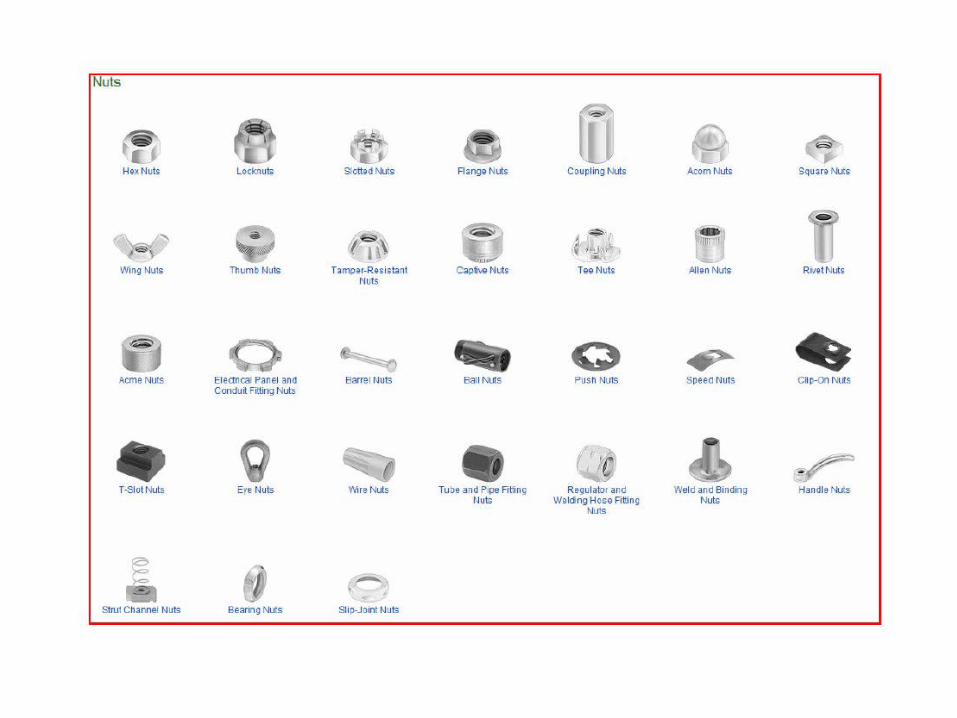
Common types of nuts
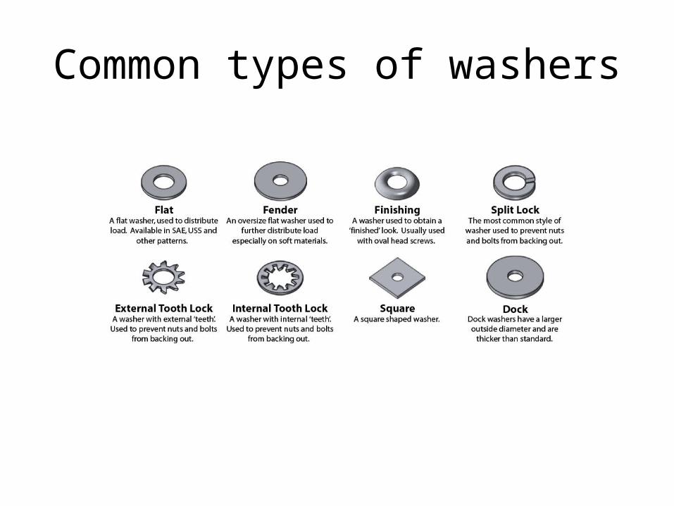
Common types of washers

Common fastener coatings
Zinc PlatingMany steel fasteners are electro-plated with zinc for better corrosion resistance. Fasteners that have been zinc plated have a shiny silver or golden appearance referred to as clear or yellow zinc respectively. They are fairly corrosion resistant but will rust if the coating is destroyed or if exposed to a marine environment. Hot Dip GalvanizingGalvanizing is another coating involving the application of a layer of zinc. Hot dipped galvanizing puts the thickest possible coating on the metal resulting in superior corrosion resistance. Due to the thickness of the coating hot dipped galvanized bolts are not compatible with other nuts. Galvanized nuts are tapped slightly larger than other nuts to accommodate this coating. Hot dipped galvanized fasteners are frequently seen in coastal environments. ChromeChrome is used in plating fasteners for its appearance. It provides similar corrosion resistance to zinc plating. The main drawback of chrome is the extremely high cost. If more corrosion resistance is required stainless steel may be chrome plated, preventing any corrosion should the chrome be penetrated.

Socket head cap screw and set screw basics

Design and Assembly
Considerations

Coarse vs. Fine ThreadsCoarse Threads
For most applications, course threads offer these advantages:
•Easier and faster assembly, providing a better start with less chance of cross threading. •Nicks and burrs from handling are less liable to affect assembly. •They are less likely to seize in temperature applications and in joints where corrosion will form. •Less prone to strip when threaded into lower strength metals. •More easily tapped in brittle materials and or materials that crumble easily.
Fine Threads
Fine threads may make for a superior fastener for applications with specific strength or other requirements.
•They are about 10% stronger that coarse threads due to their greater cross-section area. •In very hard materials, fine threads are easier to tap. •They can be adjusted more precisely because of their smaller helix angle. •Where length of engagement is limited, they provide greater strength. •Thinner wall thickness can be used because of their smaller thread cross section.

Bolted joint designsThere are two main types of bolted joint designs. In one method the bolt is tightened to a calculated clamp load, usually by applying a measured torque load. The joint will be designed such that the clamp load is never overcome by the forces acting on the joint (and therefore the joined parts see no relative motion).
This type of joint design provides several properties:•Greater preloads in bolted joints reduce the fatigue loading of the fastener.•For cyclic loads, the fastener is not subjected to the full amplitude of the load; as a result, the fastener's fatigue life can be increased or—if the material exhibits an endurance limit—extended indefinitely.•As long as the external loads on a joint don't exceed the clamp load, the fastener is not subjected to any motion and will not come loose, obviating the need for locking mechanisms.
Quality Control in the Tightening of Bolts
• The critical weakness in many products is the region of joints which exist in the design. A single bolt, inaccurately or incorrectly tightened, can lead to the failure of the complete product. Too high a tightening torque and the Engineer sustains the risk of a bolt shank or thread stripping failure. Too low a specified torque and the bolt tension can be inadequate to meet functional requirements. Failure to meet the tightening specification can have unfortunate consequences for the reliability of the product. Such failures could occur either during production assembly or during subsequent maintenance on the product after it had entered service. Either is obviously undesirable.
• The most prevalent controlled method of tightening threaded fasteners is by tightening so that a specified torque is achieved. This method is generally known as torque control. The major problem related to this method is that the clamp force generated as the result of an applied torque is dependent upon the design of the fastener and the prevailing frictional conditions. Despite these problems, it is still the most popular way of ensuring that an assembled bolt complies with an engineering specification.

Quality Control in the Tightening of Bolts

Bolt PreloadSetting the torque
• Engineered joints require the torque to be accurately set. Setting the torque for fasteners is commonly achieved using a torque wrench. The required torque value for a particular fastener application may be quoted in the published standard document or defined by the manufacturer.
• The clamp load produced during tightening is higher than 75% of the fastener's proof load. To achieve the benefits of the preloading, the clamping force must be higher than the joint separation load. For some joints, multiple fasteners are required to secure the joint; these are all hand tightened before the final torque is applied to ensure an even joint seating.
Bolt PreloadTorque Turn to Tighten
Is a method of tightening a fastener that is much more accurate than measuring resistance to turn. It’s called Torque Turn to Tighten (TTT), often referred to as angle turn. With this method, you use a relative low torque to run down and align the fastener then rely solely on a measured turn to tighten the fastener to the desired level. What we’ve done has not affected the friction in our fastener, it has taken it out of the equation when it comes to tightening. TTT is a far superior method of tightening critical fasteners regardless of whether you tighten them to yield or not.

Bolt PreloadYield Controlled Tightening
This method, developed by the SPS organization, is also known under the proprietary name "Joint Control Method". Very accurate preloads can be achieved by this method by minimizing the influence of friction and its scatter. The method has its roots in a craftsman's "sense of feel" on the wrench which allowed him to detect the yield point of the fastener with reasonable precision. With the electronic equivalent of this method, a control system is used which is sensitive to the torque gradient of the bolt being tightened. Rapid detection of the change in slope of this gradient indicates the yield point has been reached and stops the tightening process. This is achieved by incorporating sensors to read torque and angle during the tightening process. Since angle of rotation and torque are both measured by the control system, permissible values can be used to detect fasteners which lie outside their specification (having too low a yield for example).
The method has been used in critical applications, such as cylinder head and conn-rod bolts, in order that consistently high preloads can be achieved (which can allow smaller bolts to be used). However, because of the cost of the tools necessary to use this method (a hand wrench incorporating the control circuitry costs many times more than a conventional torque wrench), widespread adoption of this method is unlikely. (Although manufacturers may be able to invest in the equipment, unless service staff have similar equipment, the Designer cannot depend upon high preloads being maintained in the field.)

Torque To Yield BoltsIn the mid 1980s, we started to see a move in engine fasteners to a new process called torque-to-yield (TTY). Head bolts were the first fasteners affected, although the technology has trickled down to other critical fasteners. The theory holds that the farther we stretch a fastener toward the threshold of yield, the more load it exerts on the joint.
Now you might say, "If we want more load, we can always use a bigger diameter fastener." That’s correct. Let’s use our (hypothetical) gasket example from Victor Reinz. We need 11,900 lbs. of load on each bolt. We can get that load by stretching a 7/16" diameter bolt to the threshold of yield or by putting a very moderate load (requiring very little stretch) on a 9/16" diameter bolt. The concern is on a head bolt application is that you get lots of change in the joint. Both gasket relaxation on a new installation, as well as thermal expansion on bi-metal designs will cause changes to the joint dimension once the installation is complete. Head gasket relaxation causes loss of load from the fastener. The less stretch you have on the fastener, the more the loss of load. Let’s work our theoretical example:•7/16" fastener stretched .070" equals 11,900 lbs. of load;•9/16" fastener stretched .030" equals 11,900 lbs. of load;•A composition gasket installed at .045" relaxes 25%, for a net loss of .011";•7/16" fastener loses 1/7 of the load, leaving 10,200 lbs.; and•9/16" fastener loses 1/3 of the load, leaving 7,933 lbs.

Bolted joint designs
The other type of bolted joint does not have a designed clamp load but relies on the shear strength of the bolt shaft. This may include clevis linkages, joints that can move, and joints that rely on a locking mechanism (like lock washers, thread adhesives, and lock nuts).
Single shear load
Double shear load

Strength Definitions

Bolted joint spring analogy
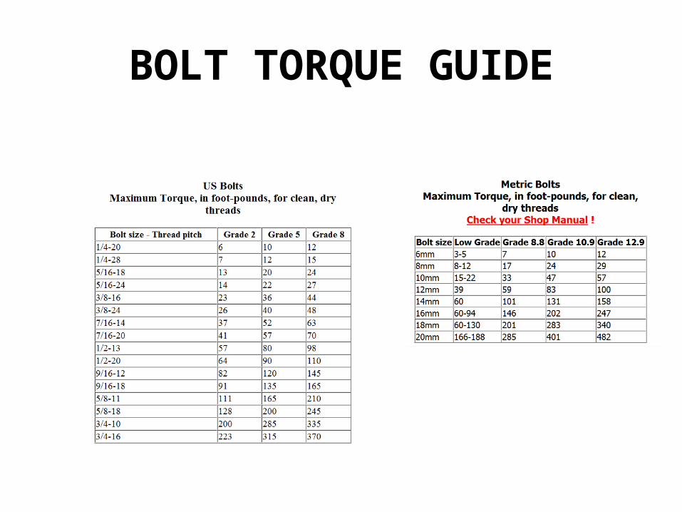
BOLT TORQUE GUIDE

The Engineers Rule

Wrench Clearance

Quality of bolts and Screws

Quality of bolts and ScrewsAt the time that I wrote that particular article there was only one company hyping bad bolts to the racers as superior to SAE Grade 8, and, more important, all of the SAE grade marked hardware was being produced in this country. Now there are several corporations hyp ing junk, and there are inferior bolts coming from the smaller "offshore island" with head markings identical to those designated by the SAE for Grade 5 and Grade 8.They are also counterfeiting various grades of metric bolts. The SAE is up in arms, the popular press is onto the scam with front-page stories of wheels falling off military vehicles and so on, and the FAA, realizing that many aerospace bolts are no more difficult to counterfeit than SAE bolts, is terri fied.
At this moment, the Nuclear Regulatory Commission is investigating fifty-six companies suspected of dealing in coun terfeit parts. The NRC has reported that half of the 110 nuclear plants in the United States contain counterfeit or defective fasteners.
NUTS, BOLTS, FASTENERS AND PLUMBING HANDBOOK, CARROLL SMITH,1990

Quality of bolts and Screws
• Item: Boeing discovered 2,000 counterfeit bearings in 737,747,757 and 767 jets manufactured between April 1986 and January 1988. Routine tests revealed that the bearings were defective. The bearings carried the markings of a US manufacturer but were actually made in Japan to less stringent standards.
• Item: The FAA lists sixty-seven aircraft inci dents caused by fastener failure between 1984 and 1987. The FAA is now investigating how many of the failed fasteners were counterfeit.
• Item: NASA had to disassemble the Astro I space lab to remove counterfeit and defective fas teners. The cost was over $1 million. NASA had purchased the fasteners from a California distribu tor that was low bidder. It turned out to be one man operating out of his garage.
• Item: NASA removed counterfeit bolts from the space shuttle Discovery before its successful launch.
NUTS, BOLTS, FASTENERS AND PLUMBING HANDBOOK, CARROLL SMITH,1990

Quality of bolts and Screws
• Don't be deceived! Use no bolts that are not AN/NAS/MS certified, US-made, SAE-graded, or manufactured with UNR threads. The super-whatever bolts are not designed for fatigue-prone applications. The quality control exercised in their manufacture is minimal or nonexistent.

How the ‘AN’ System Started If aircraft hardware is special, then there must be a standard against which it should be measured and manufactured. That standard was actually developed prior to World War II, but became more definitive during that war. Each branch of the military originally had its own standard for hardware. As time went on these standards were consolidated and thus the term AN which means Air Force-Navy (some prefer the older term Army-Navy). Later the standards were termed MS which means Military Standard and NAS which means National Aerospace Standards. Thus, the common terms AN, MS and NAS. Together they present a universally accepted method of identification and standards for aircraft hardware. All fasteners are identified with a specification number and a series of letters and dashes identifying their size, type of material, etc. This system presents a relatively simple method of identifying and cataloging the thousands and thousands of pieces of hardware. Several pieces of hardware will have both an AN number and an MS number that are used interchangeably to identify the exact same piece.
Basically, the AN, MS and NAS hardware offers a range of fasteners designed to do a job similar to ours and which are manufactured and inspected to stringent standards. Dimensions are closely con trolled; surfaces are fully finished and true; and strength and hardness are consistent and depend able. They are not only strong, they are very tough. These bolts will bend before they break. Every con ceivable size and configuration is available.
The AN and MS items are actually price-competitive with both SAE Grade 8 and the best commercial socket-head cap screws.
NUTS, BOLTS, FASTENERS AND PLUMBING HANDBOOK, CARROLL SMITH,1990


Basic AN Sizes

AN Bolt Head Designations

Safety Wire Applications

ASTM Bolt Head MarkingsUsed for structural purposes