
Fast Z-Pinch Experiments at the Kurchatov Institute Aimed at the Inertial Fusion Energy A.Kingsep...
21
Fast Z-Pinch Experiments at the Kurchatov Institute Aimed at the Inertial Fusion Energy A.Kingsep 1), S.Anan’ev 1), Yu. Bakshaev 1), A. Bartov 1), P. Blinov 1), A.Chernenko 1), S. Danko 1), Yu. Kalinin 1), E. Kazakov 1), V. Korolev 1), M. Mazarakis 2) V. Mizhititsky 1), C. Olson 2), P.Sasorov 3), V. Smirnov 1) 1) Russian Research Centre “Kurchatov Institute”, Moscow, Russia Russian Research Centre “Kurchatov Institute” RRC KI
-
Upload
emil-norris -
Category
Documents
-
view
216 -
download
2
Transcript of Fast Z-Pinch Experiments at the Kurchatov Institute Aimed at the Inertial Fusion Energy A.Kingsep...
Fast Z-Pinch Experiments at the Kurchatov Institute
Aimed at the Inertial Fusion Energy
A.Kingsep 1), S.Anan’ev 1), Yu. Bakshaev 1), A. Bartov 1), P. Blinov 1), A.Chernenko 1), S. Danko 1), Yu. Kalinin 1),
E. Kazakov 1), V. Korolev 1), M. Mazarakis 2) V. Mizhititsky 1), C. Olson 2), P.Sasorov 3), V. Smirnov 1)
1) Russian Research Centre “Kurchatov Institute”, Moscow, Russia 2) Sandia National Laboratories, Albuquerque NM, USA3) Institute for Theoretical and Experimental Physics, Moscow, Russia
Russian Research Centre“Kurchatov Institute”
RRC KI

The basic functional elements of ZP-3 reactor chamber
I = 60 МА - for ignition.I = 90 МА - for IFE power plant.Thickness of bringing electrodes: 100 – 200 m.

SCHEMATIC OF THE REACTOR CHAMBER
0 1 2 3 4 5 6 7 8 9 10 m
0
1
2
3
4
5
6
7
8
9
10m
Fusion target
RTL
30 planar/coaxialMITL
60 planarMITL
Reactorchamber
Liquid Li & Pb pool
RTL input
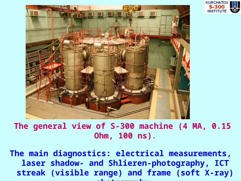
The general view of S-300 machine (4 MA, 0.15 Ohm, 100 ns).
The main diagnostics: electrical measurements, laser shadow- and Shlieren-photography, ICT streak (visible
range) and frame (soft X-ray) photography.
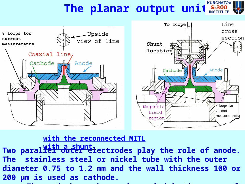
The planar output units
with the reconnected MITL with a shunt
Two parallel outer electrodes play the role of anode. The stainless steel or nickel tube with the outer diameter 0.75 to 1.2 mm and the wall thickness 100 or 200 µm is used as cathode.
The cathode-anode gap is varied in the range of 3.5 – 5 mm.

The axial output units
;

Examples of shadow photographs. The boundary of shadow corresponds to the ion density ~61018 cm-3 .
Examples of the Schlieren photographs. The contour boundary corresponds to the electron density ~5·1017 cm-3.
The diameter of cathode plasma determined from the shadow and
Schlieren photographs.
Plasma with the electron density not less than 51017 cm-3 expands along the radius not faster than 1.1 mm up to the 240 ns. Its space scale is less
than the gap width.
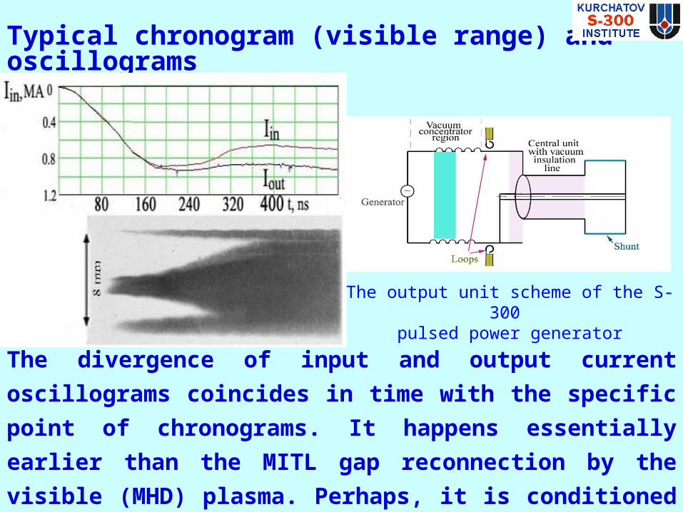
Typical chronogram (visible range) and oscillograms
The divergence of input and output current oscillograms coincides in
time with the specific point of chronograms. It happens essentially
earlier than the MITL gap reconnection by the visible (MHD)
plasma. Perhaps, it is conditioned by the dynamics and/or instability
of very rare plasma.
The output unit scheme of the S-300 pulsed power generator

Chronogram of the cathode plasma expansion (the negative).
The superposition of experimental chronogram (blue – violet – yellow order corresponds to the increasing density) on the simulation results .
The experimental temporal profile of the dense plasma boundary coincides with the calculated one resulting from the MHD simulations up to compression maximum; then expansion velocity increases sharply (specific point - jump).The chronogram reveals also the region of rather rare plasma (bounded by the blue curve) that cannot be identified within the frames of MHD model.

Period l=0.7mm l=1,2mm l=1,5mm l= 5mm
ICT photographs of the plasma surrounding the central electrode in the SXR range. The property typical of EMHD instabilities is the space scale increasing in time

In this series, the inner tube was coated by ceramics
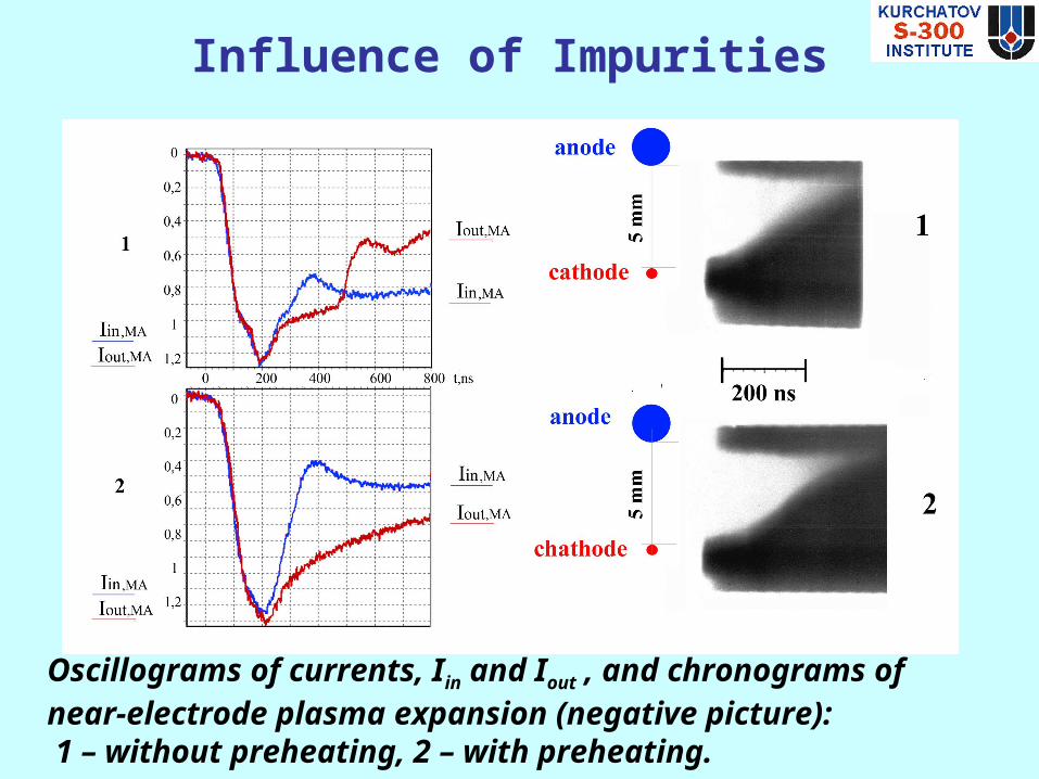
Influence of Impurities
Oscillograms of currents, Iin and Iout , and chronograms of near-electrode plasma expansion (negative picture): 1 – without preheating, 2 – with preheating.

Effect of Electrode Materials I
Aluminum Lead
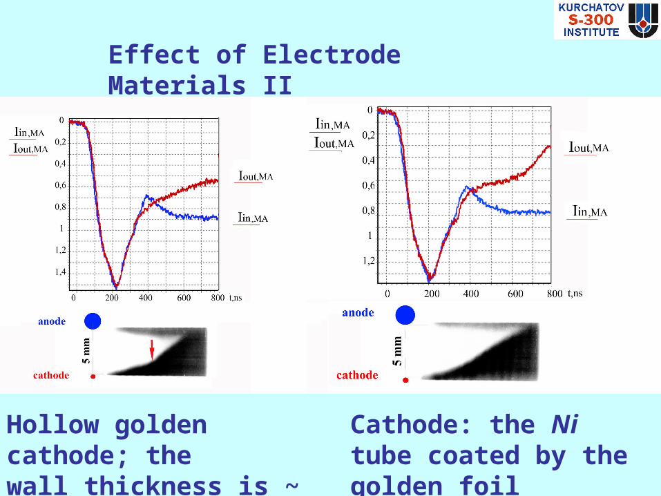
Effect of Electrode Materials II
Cathode: the Ni tube coated by the golden foil
Hollow golden cathode; thewall thickness is ~ 200 m

The scheme of Bremsstrahlung recording
I< 100 Ka < 10% Ifull

Input current oscillogram (I in ) and plasma expansion chronogram (negative). The strike points the plasma filament.
Dynamics of Rare Plasma Component
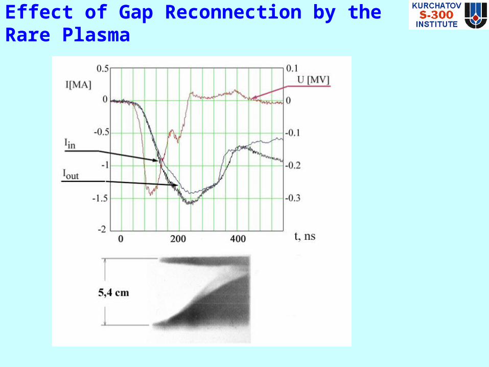
Effect of Gap Reconnection by the Rare Plasma
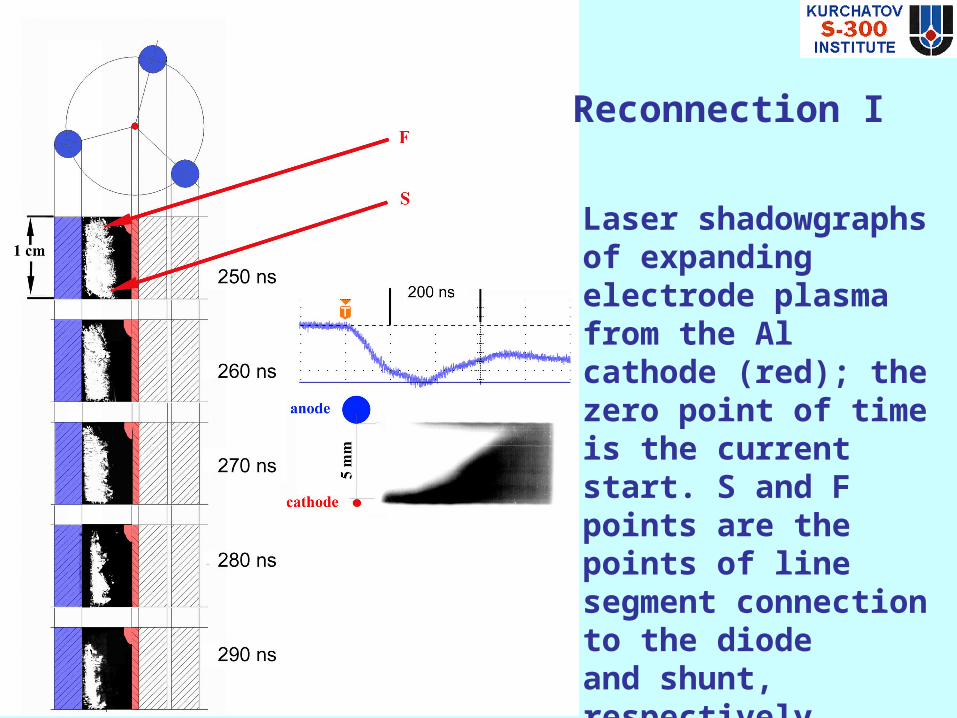
Laser shadowgraphs of expanding electrode plasma from the Al cathode (red); the zero point of time is the current start. S and F points are the points of line segment connection to the diode and shunt, respectively. Right: the oscillogram of input current and the chronogram of plasma expansion.
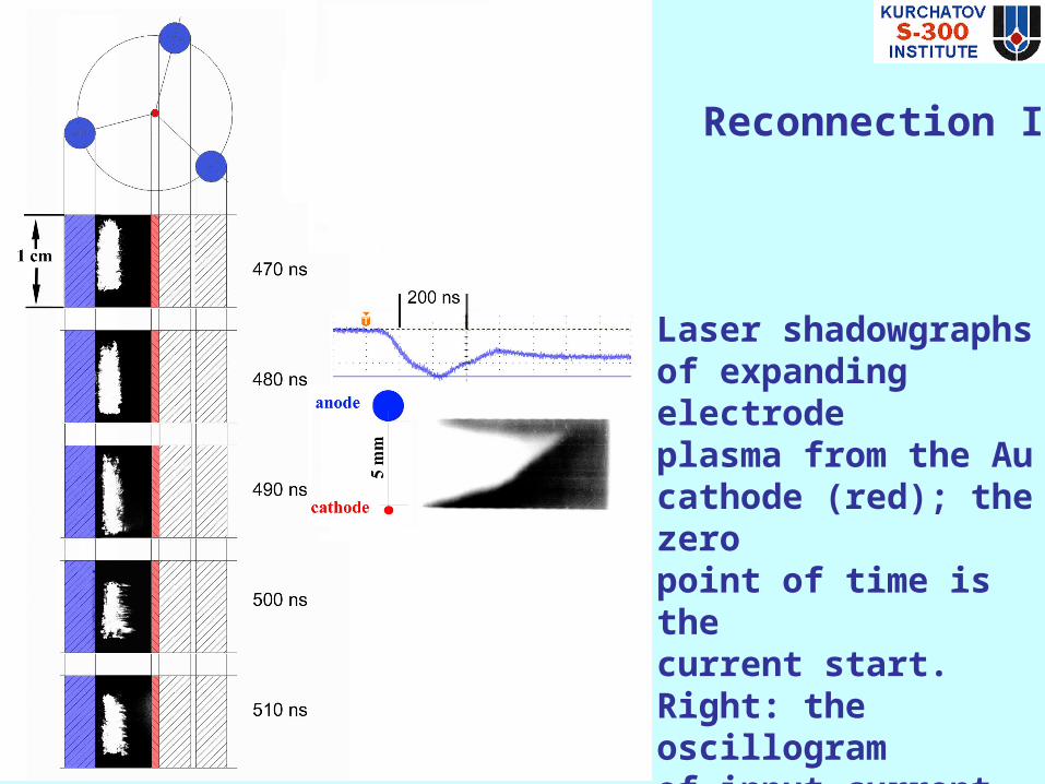
Reconnection I
Reconnection II
Laser shadowgraphs of expanding electrode plasma from the Au cathode (red); the zero point of time is the current start. Right: the oscillogram of input current and the chronogram of plasma expansion.

CONCLUSIONS• A series of experiments has been carried out aimed at
the investigation of the MITL section at the linear current densities up to 7 MA/cm that is typical of the Pulsed Power Fusion Energy plant.
• The temporal behavior of both input and output current in the MITL section is identical up to 200-260 ns for the light cathode materials, and up to 400 ns for heavy materials. At this stage, it has been found that the plasma formed as a result of electrode surface explosion, did not reconnect the MITL gap.
• Except of dense MHD plasmas, effects of rare EMHD plasmas join the game. In particular, they manifest themselves in the fast instability of plasma sheath and may be responsible for the MITL reconnection.

• The process of electrode explosion and subsequent plasma dynamics fairly corresponds to the predictions of numerical simulations based on the NPINCH code taking into account EOS for metals and plasmas.
• The electric explosion at the final recycled segment of magnetically insulated transporting line does not prevent from the energy transport towards the target. As a whole, our works allow to draw a positive conclusion concerning prospects of use the recyclable MITL for transportation of energy onto the target of Z-pinch IFE reactor.
CONCLUSIONS, continued