Fast SIMPACK WIND - German Pavilion · SIMPACK WIND Accurate • Fast • Robust • Versatile What...
9
SIMPACK WIND Accurate • Fast • Robust • Versatile What is SIMPACK? SIMPACK is a general-purpose multi-body simulation (MBS) software tool which is used to aid the development of any mechanical or mechatronic device, ranging from single components through to complete systems, e.g. wind turbines, vehicles, and high performance Formula 1 engines. All SIMPACK products are 100% compatible. SIMPACK Wind is an add-on module tailored to the specific requirements of the wind turbine sector. Applications: Simulation of any wind turbine design Resonance analysis Stochastic and transient response Geometric and material modification Optimization Durability Hardware-Software-in-the-loop Highlights: Simulation of any design Extreme non-linear system behavior, e.g. emergency braking Acoustic analyses in the frequency and time domain Interfaces to aerodynamic codes, e.g. from NREL and ECN Scalable detail and complexity Batch jobs Automatic analysis reports Flexible rotorblade generator Available wind turbine models with highly detailed drivetrains Application
Transcript of Fast SIMPACK WIND - German Pavilion · SIMPACK WIND Accurate • Fast • Robust • Versatile What...
SIMPACK WIND Accurate • Fast • Robust • Versatile
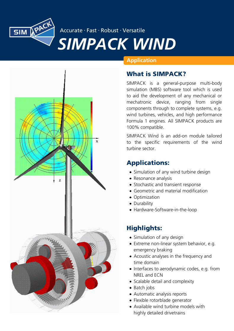
What is SIMPACK?
SIMPACK is a general-purpose multi-body
simulation (MBS) software tool which is used
to aid the development of any mechanical or
mechatronic device, ranging from single
components through to complete systems, e.g.
wind turbines, vehicles, and high performance
Formula 1 engines. All SIMPACK products are
100% compatible.
SIMPACK Wind is an add-on module tailored
to the specific requirements of the wind
turbine sector.
Applications:
Simulation of any wind turbine design
Resonance analysis
Stochastic and transient response
Geometric and material modification
Optimization
Durability
Hardware-Software-in-the-loop
Highlights:
Simulation of any design
Extreme non-linear system behavior, e.g.
emergency braking
Acoustic analyses in the frequency and
time domain
Interfaces to aerodynamic codes, e.g. from
NREL and ECN
Scalable detail and complexity
Batch jobs
Automatic analysis reports
Flexible rotorblade generator
Available wind turbine models with
highly detailed drivetrains
Application
Features:
Detailed gear pairs, originally developed for Formula 1
Dynamic separation of gear pairs
Flexible body generation within SIMPACK
Importation of flexible bodies from FEM codes
Non-linear bending
Easy implementation of user specific code
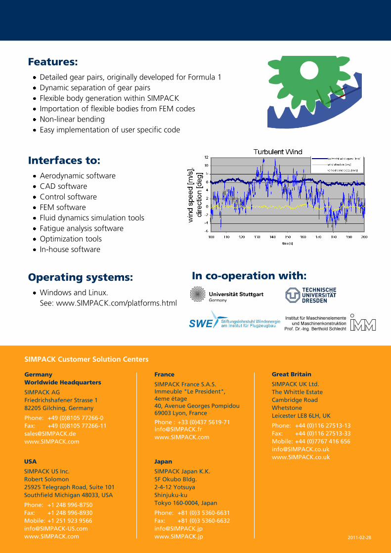
Interfaces to:
Aerodynamic software
CAD software
Control software
FEM software
Fluid dynamics simulation tools
Fatigue analysis software
Optimization tools
In-house software
Operating systems:
Windows and Linux.
See: www.SIMPACK.com/platforms.html
In co-operation with:
2011-02-28
SIMPACK Customer Solution Centers
Germany
Worldwide Headquarters
SIMPACK AG
Friedrichshafener Strasse 1
82205 Gilching, Germany
Phone: +49 (0)8105 77266-0
Fax: +49 (0)8105 77266-11
www.SIMPACK.com
Great Britain
SIMPACK UK Ltd.
The Whittle Estate
Cambridge Road
Whetstone
Leicester LE8 6LH, UK
Phone: +44 (0)116 27513-13
Fax: +44 (0)116 27513-33
Mobile: +44 (0)7767 416 656
www.SIMPACK.co.uk
France
SIMPACK France S.A.S.
Immeuble "Le President",
4eme étage
40, Avenue Georges Pompidou
69003 Lyon, France
Phone : +33 (0)437 5619-71 [email protected]
www.SIMPACK.com
Japan
SIMPACK Japan K.K.
5F Okubo Bldg.
2-4-12 Yotsuya
Shinjuku-ku
Tokyo 160-0004, Japan
Phone: +81 (0)3 5360-6631
Fax: +81 (0)3 5360-6632
www.SIMPACK.jp
USA
SIMPACK US Inc.
Robert Solomon
25925 Telegraph Road, Suite 101
Southfield Michigan 48033, USA
Phone: +1 248 996-8750
Fax: +1 248 996-8930
Mobile: +1 251 923 9566
www.SIMPACK.com
w.
Accurate • Fast • Robust • Versatile
SIMPACK DRIVETRAIN
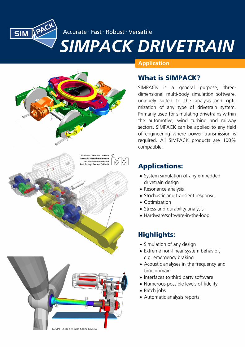
What is SIMPACK?
SIMPACK is a general purpose, three-
dimensional multi-body simulation software,
uniquely suited to the analysis and opti-
mization of any type of drivetrain system.
Primarily used for simulating drivetrains within
the automotive, wind turbine and railway
sectors, SIMPACK can be applied to any field
of engineering where power transmission is
required. All SIMPACK products are 100%
compatible.
Applications:
System simulation of any embedded
drivetrain design
Resonance analysis
Stochastic and transient response
Optimization
Stress and durability analysis
Hardware/software-in-the-loop
Highlights:
Simulation of any design
Extreme non-linear system behavior,
e.g. emergency braking
Acoustic analyses in the frequency and
time domain
Interfaces to third party software
Numerous possible levels of fidelity
Batch jobs
Automatic analysis reports
KOMAI TEKKO Inc.: Wind turbine KWT300
Application
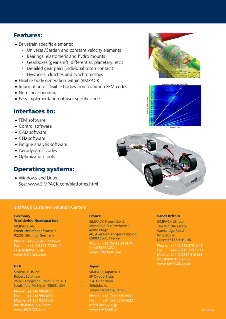
Features:
Drivetrain specific elements:
- Universal/Cardan and constant velocity elements
- Bearings, elastomeric and hydro mounts
- Gearboxes (gear shift, differential, planetary, etc.)
- Detailed gear pairs (individual tooth contact)
- Flywheels, clutches and synchromeshes
Flexible body generation within SIMPACK
Importation of flexible bodies from common FEM codes
Non-linear bending
Easy implementation of user specific code
Interfaces to:
FEM software
Control software
CAD software
CFD software
Fatigue analysis software
Aerodynamic codes
Optimization tools
Operating systems:
Windows and Linux.
See: www.SIMPACK.com/platforms.html
2011-02-24
SIMPACK Customer Solution Centers
Germany
Worldwide Headquarters
SIMPACK AG
Friedrichshafener Strasse 1
82205 Gilching, Germany
Phone: +49 (0)8105 77266-0
Fax: +49 (0)8105 77266-11
www.SIMPACK.com
Great Britain
SIMPACK UK Ltd.
The Whittle Estate
Cambridge Road
Whetstone
Leicester LE8 6LH, UK
Phone: +44 (0)116 27513-13
Fax: +44 (0)116 27513-33
Mobile: +44 (0)7767 416 656
www.SIMPACK.co.uk
France
SIMPACK France S.A.S.
Immeuble "Le President",
4eme étage
40, Avenue Georges Pompidou
69003 Lyon, France
Phone : +33 (0)437 5619-71 [email protected]
www.SIMPACK.com
Japan
SIMPACK Japan K.K.
5F Okubo Bldg.
2-4-12 Yotsuya
Shinjuku-ku
Tokyo 160-0004, Japan
Phone: +81 (0)3 5360-6631
Fax: +81 (0)3 5360-6632
www.SIMPACK.jp
USA
SIMPACK US Inc.
Robert Solomon
25925 Telegraph Road, Suite 101
Southfield Michigan 48033, USA
Phone: +1 248 996-8750
Fax: +1 248 996-8930
Mobile: +1 251 923 9566
www.SIMPACK.com
SIMPACK News | September 2010 | 25
Steven Mulski, SIMPACK AG | SoftwAre
Gear Pair enhancements with SIMPACK Version 8904
HIStorYInitially developed for Formula 1 high performance engines back in 2003 (by Lutz Mauer, an executive board member of SIMPACK AG), the SIMPACK Gear Pair functionality has since been used in a large variety of industrial sectors, e.g. automotive, wind, rail, shipping, aerospace, concrete mills, material handling, etc.
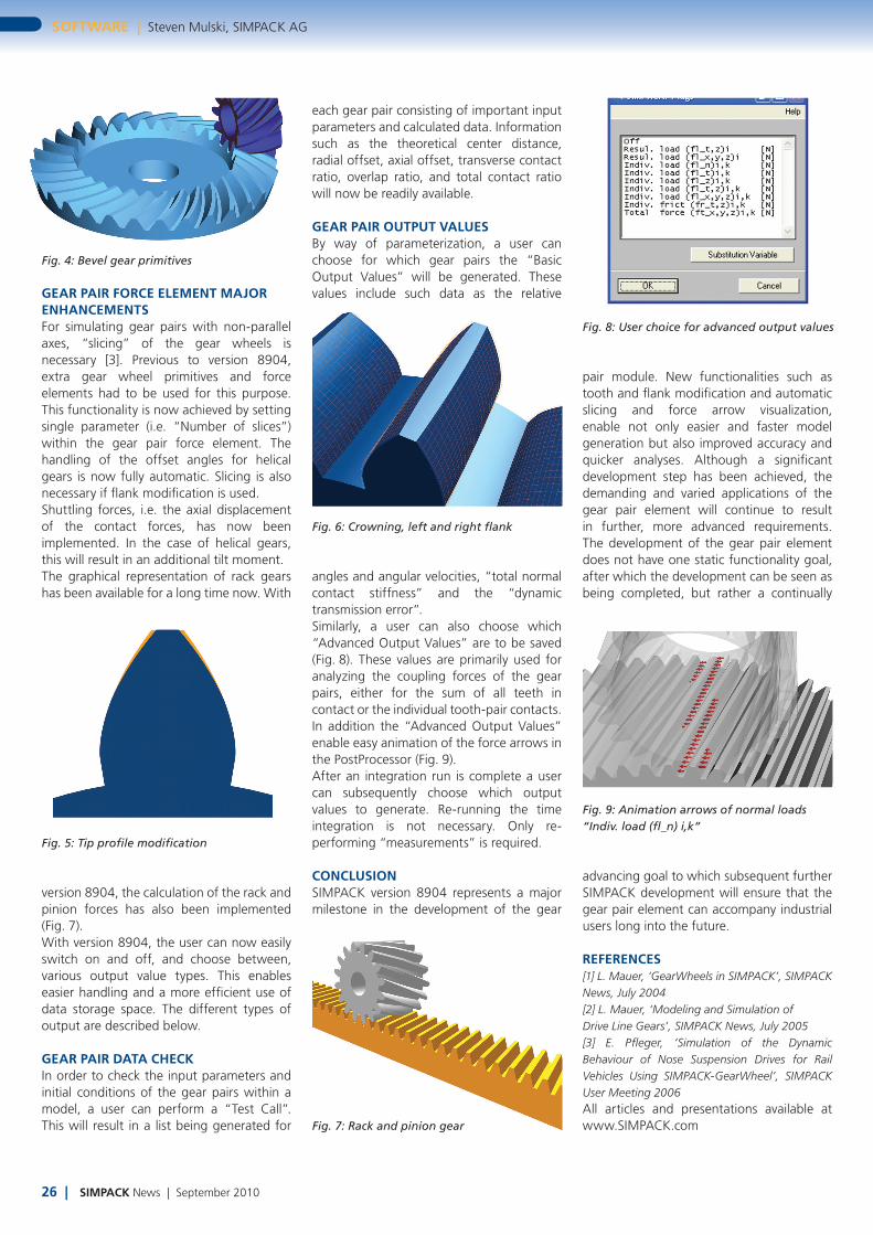
GeNerALIn SIMPACK, a large variety of elements are available for the simulation of torque converters. Depending upon the task at hand, elements of various level of detail may be used for achieving the optimum balance between solver speed and accuracy. For example, simple one-dimensional elements may be used for torsional analyses whereas gearbox elements (e.g. planetary gear stage) may be used for more detailed analyses when reaction moments on the housing are required. For simulations where individual tooth contact forces are required, the SIMPACK Gear Pair force element, FE 225, may be used. This element enables the additional analyses of the meshing forces and moments, shaft bending, bearing
forces, and a host of other pertinent analyses (Fig. 2).The gear pair FE 225 is an analytical element, and therefore, extremely fast simulation times can be achieved. Graphical primitives are defined for the gear wheels which are subsequently used for the force calculations. This results in accurate animation of the gear tooth contacts and play.
The element includes the following functionality [1, 2]:• Involute spur, helical and bevel gears• Internal and external gears• Profile Shift• Backlash and friction• Single and multiple tooth contact (internal
excitations due to tooth meshing)• Dynamically changing gear pair center
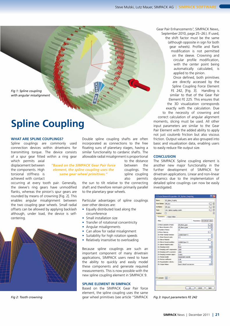
distance and backlash (particularly important for floating suns (Fig. 3) and elastically mounted shafts)
The major gear pair enhancements with version 8904 are:• Rack and pinion gearing• Bevel gear primitive• Tooth modification• Flank modification• Shuttling forces• Easy slicing for non-parallel gear wheels
and gear wheels with flank modification• Easy handling of output values and
animation of contact forces
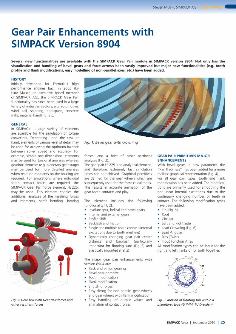
GeAr PAIr PrIMItIVeS MAJor eNHANCeMeNtSWith bevel gears, a new parameter, the “Rim thickness”, has been added for a more realistic graphical representation (Fig. 4). For all gear pair types, tooth and flank modification has been added. The modifica-tions are primarily used for smoothing the non-linear internal excitations due to the continually changing number of teeth in contact. The following modification types have been added:• Tip (Fig. 5)• Root• Circular• Left and Right Side• Lead Crowning (Fig. 6)• Lead Angular• Bias (Twist)• Input Function ArrayAll modification types can be input for the right and left flanks or for both together.
Fig. 1: Bevel gear with crowning
Fig. 2: Gear box with Gear Pair forces and other resultant forces
Fig. 3: Motion of floating sun within a planetary stage (© IMM, TU Dresden)
Several new functionalities are available with the SIMPACK Gear Pair module in SIMPACK version 8904. Not only has the visualization and handling of bevel gears and force arrows been vastly improved but major new functionalities (e.g. tooth profile and flank modifications, easy modelling of non-parallel axes, etc.) have been added.
26 | SIMPACK News | September 2010
SoftwAre | Steven Mulski, SIMPACK AG
GeAr PAIr forCe eLeMeNt MAJor eNHANCeMeNtSFor simulating gear pairs with non-parallel axes, “slicing” of the gear wheels is necessary [3]. Previous to version 8904, extra gear wheel primitives and force elements had to be used for this purpose. This functionality is now achieved by setting single parameter (i.e. “Number of slices”) within the gear pair force element. The handling of the offset angles for helical gears is now fully automatic. Slicing is also necessary if flank modification is used. Shuttling forces, i.e. the axial displacement of the contact forces, has now been implemented. In the case of helical gears, this will result in an additional tilt moment.The graphical representation of rack gears has been available for a long time now. With
Fig. 4: Bevel gear primitives
Fig. 5: Tip profile modification
Fig. 8: User choice for advanced output values
Fig. 7: Rack and pinion gear
Fig. 6: Crowning, left and right flank
Fig. 9: Animation arrows of normal loads “Indiv. load (fl_n) i,k”
version 8904, the calculation of the rack and pinion forces has also been implemented (Fig. 7). With version 8904, the user can now easily switch on and off, and choose between, various output value types. This enables easier handling and a more efficient use of data storage space. The different types of output are described below.
GeAr PAIr DAtA CHeCKIn order to check the input parameters and initial conditions of the gear pairs within a model, a user can perform a “Test Call”. This will result in a list being generated for
each gear pair consisting of important input parameters and calculated data. Information such as the theoretical center distance, radial offset, axial offset, transverse contact ratio, overlap ratio, and total contact ratio will now be readily available.
GeAr PAIr oUtPUt VALUeSBy way of parameterization, a user can choose for which gear pairs the “Basic Output Values” will be generated. These values include such data as the relative
angles and angular velocities, “total normal contact stiffness” and the “dynamic transmission error”.Similarly, a user can also choose which “Advanced Output Values” are to be saved (Fig. 8). These values are primarily used for analyzing the coupling forces of the gear pairs, either for the sum of all teeth in contact or the individual tooth-pair contacts. In addition the “Advanced Output Values” enable easy animation of the force arrows in the PostProcessor (Fig. 9).After an integration run is complete a user can subsequently choose which output values to generate. Re-running the time integration is not necessary. Only re-performing “measurements” is required.
CoNCLUSIoNSIMPACK version 8904 represents a major milestone in the development of the gear
pair module. New functionalities such as tooth and flank modification and automatic slicing and force arrow visualization, enable not only easier and faster model generation but also improved accuracy and quicker analyses. Although a significant development step has been achieved, the demanding and varied applications of the gear pair element will continue to result in further, more advanced requirements. The development of the gear pair element does not have one static functionality goal, after which the development can be seen as being completed, but rather a continually
advancing goal to which subsequent further SIMPACK development will ensure that the gear pair element can accompany industrial users long into the future.
refereNCeS[1] L. Mauer, ‘GearWheels in SIMPACK’, SIMPACK News, July 2004[2] L. Mauer, ‘Modeling and Simulation ofDrive Line Gears’, SIMPACK News, July 2005[3] E. Pfleger, ‘Simulation of the Dynamic Behaviour of Nose Suspension Drives for Rail Vehicles Using SIMPACK-GearWheel’, SIMPACK User Meeting 2006All articles and presentations available at www.SIMPACK.com
SIMPACK News | December 2011 | 21
Steve Mulski, Lutz Mauer, SIMPACK AG | SIMPACK SoftwAre
wHAt Are SPLINe CoUPLINGS? Spline couplings are commonly used connection devices within drivetrains for transmitting torque. The device consists of a spur gear fitted within a ring gear which permits axial displacement between the components. High torsional stiffness is achieved with contact occurring at every tooth pair. Generally, the sleeve’s ring gears have unmodified flanks, whereas the pinion’s spur gears are rounded by means of crowning [Fig. 2]. This enables angular misalignment between the two coupling gear wheels. Small radial offsets can be allowed by applying backlash although, under load, the device is self-centering.
Spline CouplingDouble spline coupling shafts are often incorporated as connections to the free floating suns of planetary stages, having a similar functionality to cardanic shafts. The allowable radial misalignment is proportional
to the distance between the couplings. The spline coupling also permits
the sun to tilt relative to the connecting shaft and therefore remain primarily parallel to the planetary gear wheels.
Particular advantages of spline couplings over other devices are: • Equally distributed load along the
circumference • Small installation size • Transfer of rotational concentricity • Angular misalignments • Can allow for radial misalignment • Suitability for high rotation speeds • Relatively insensitive to overloading
Because spline couplings are such an important component of many drivetrain applications, SIMPACK users need to have the ability to quickly and easily model these components and generate required measurements. This is now possible with the new spline coupling element in SIMPACK 9.
SPLINe eLeMeNt IN SIMPACKBased on the SIMPACK Gear Pair force element, the spline coupling uses the same gear wheel primitives (see article “SIMPACK
“Based on the SIMPACK Gear Pair force element, the spline coupling uses the
same gear wheel primitives.”
Gear Pair Enhancements”, SIMPACK News, September 2010, page 25–26:). If used,
the shift factor must be the same (although opposite in sign for both gear wheels). Profile and flank modification is not permitted on the sleeve. Crowning and circular profile modification, with the center point being automatically calculated, is applied to the pinion.Once defined, both primitives are directly accessed by the Spline Coupling Force Element
FE 242, [Fig. 3]. Handling is similar to that of the Gear Pair
Element FE 225. This ensures that the 3D visualization corresponds
exactly with the calculation. Due to the necessity of crowning and
correct calculation of angular alignment moments, slicing must be used. All other input parameters are similar to the Gear Pair Element with the added ability to apply not just coulomb friction but also viscous friction. Output values are also grouped into basic and visualization data, enabling users to easily reduce file output size.
CoNCLUSIoNThe SIMPACK Spline coupling element is another new major functionality in the further development of SIMPACK for drivetrain applications. Linear and non-linear dynamics due to the implementation of detailed spline couplings can now be easily investigated.
Fig 1: Spline coupling with angular misalignment
Fig 2: Tooth crowning Fig 3: Input parameters FE 242
SIMPACK with Simulink® Accurate • Fast • Robust • Versatile
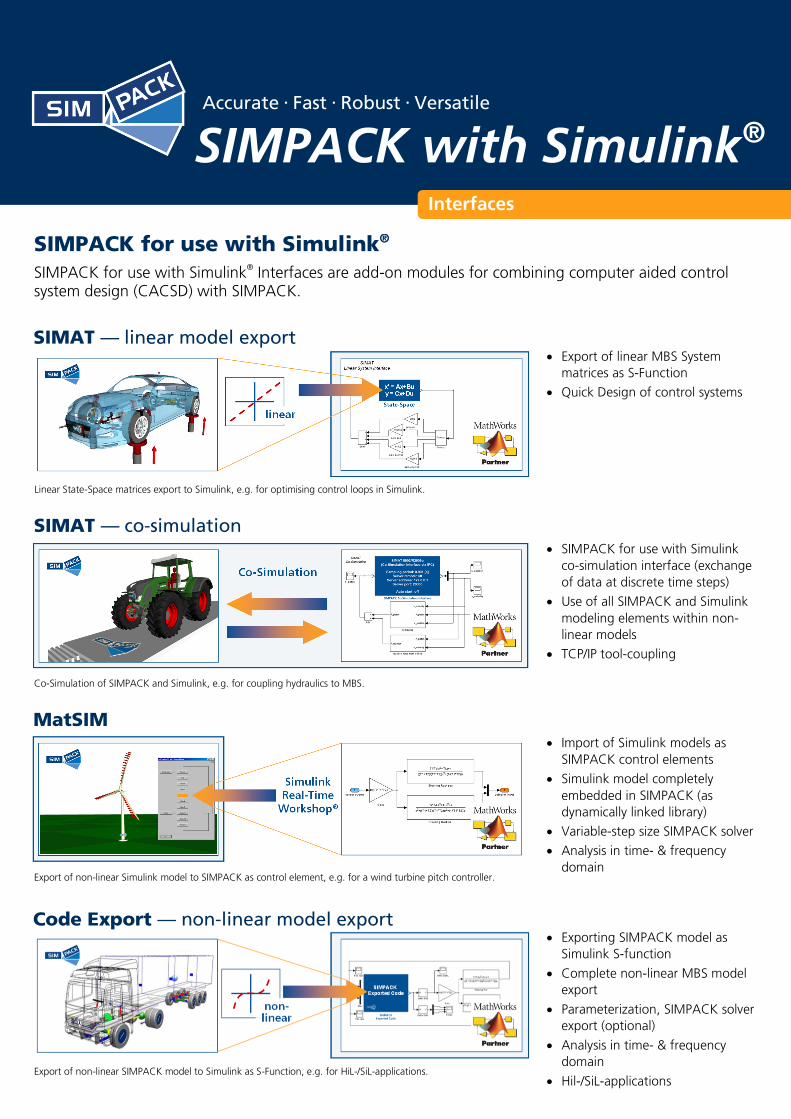
Linear State-Space matrices export to Simulink, e.g. for optimising control loops in Simulink.
Co-Simulation of SIMPACK and Simulink, e.g. for coupling hydraulics to MBS.
SIMAT — linear model export
SIMPACK for use with Simulink®
SIMPACK for use with Simulink® Interfaces are add-on modules for combining computer aided control
system design (CACSD) with SIMPACK.
SIMAT — co-simulation
Export of linear MBS System
matrices as S-Function
Quick Design of control systems
SIMPACK for use with Simulink
co-simulation interface (exchange
of data at discrete time steps)
Use of all SIMPACK and Simulink
modeling elements within non-
linear models
TCP/IP tool-coupling
MatSIM
Import of Simulink models as
SIMPACK control elements
Simulink model completely
embedded in SIMPACK (as
dynamically linked library)
Variable-step size SIMPACK solver
Analysis in time- & frequency
domain
Export of non-linear Simulink model to SIMPACK as control element, e.g. for a wind turbine pitch controller.
Code Export — non-linear model export
Exporting SIMPACK model as
Simulink S-function
Complete non-linear MBS model
export
Parameterization, SIMPACK solver
export (optional)
Analysis in time- & frequency
domain
Hil-/SiL-applications Export of non-linear SIMPACK model to Simulink as S-Function, e.g. for HiL-/SiL-applications.
Interfaces
Applications:
Combining control with MBS dynamics
Any kind of mechatronic application
Full integration of MBS into control
environment
Full integration of CACSD
into high-end MBS environment
Hardware/Software-in-the-Loop
Linear and non-linear analyses
in time- and frequency domain
What is SIMPACK?
SIMPACK is a general-purpose multi-body simulation (MBS) software tool which is used to aid the
development of any mechanical or mechatronic device, ranging from single components through to
complete systems (e.g. wind turbines, vehicles, and high performance Formula 1 engines). All
SIMPACK products are 100% compatible.
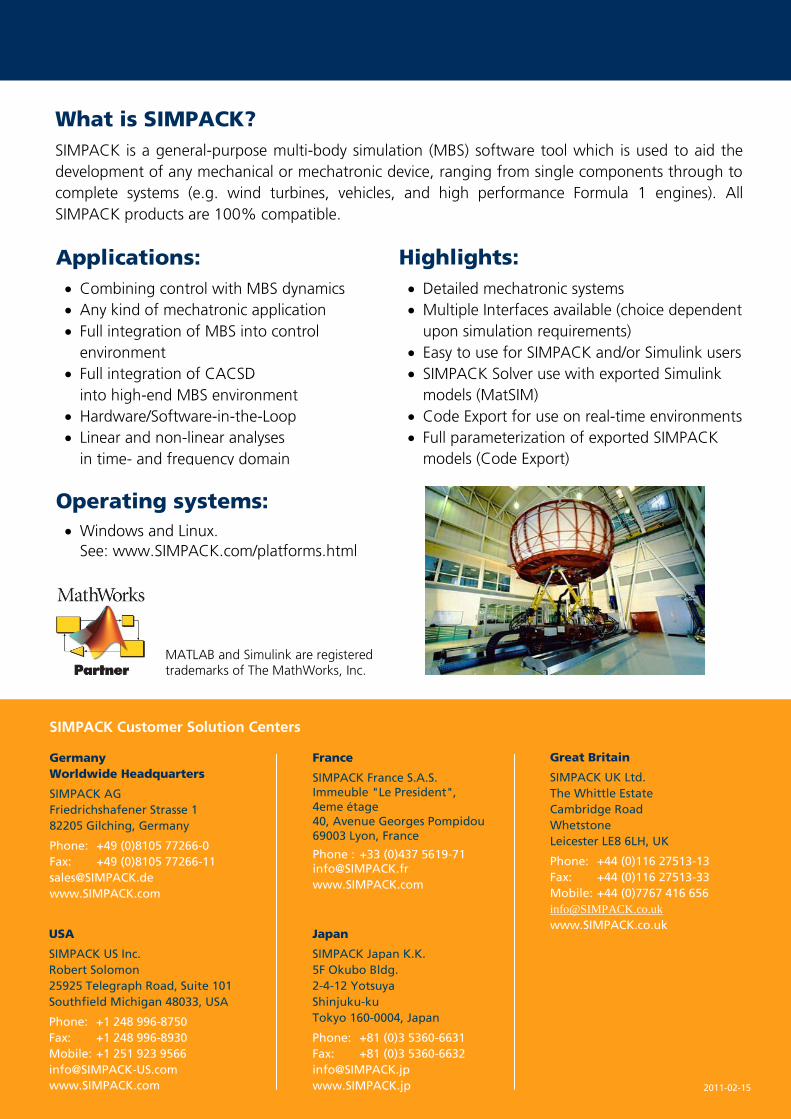
Operating systems:
Windows and Linux.
See: www.SIMPACK.com/platforms.html
Highlights:
Detailed mechatronic systems
Multiple Interfaces available (choice dependent
upon simulation requirements)
Easy to use for SIMPACK and/or Simulink users
SIMPACK Solver use with exported Simulink
models (MatSIM)
Code Export for use on real-time environments
Full parameterization of exported SIMPACK
models (Code Export)
MATLAB and Simulink are registered trademarks of The MathWorks, Inc.
2011-02-15
SIMPACK Customer Solution Centers
Germany
Worldwide Headquarters
SIMPACK AG
Friedrichshafener Strasse 1
82205 Gilching, Germany
Phone: +49 (0)8105 77266-0
Fax: +49 (0)8105 77266-11
www.SIMPACK.com
Great Britain
SIMPACK UK Ltd.
The Whittle Estate
Cambridge Road
Whetstone
Leicester LE8 6LH, UK
Phone: +44 (0)116 27513-13
Fax: +44 (0)116 27513-33
Mobile: +44 (0)7767 416 656
www.SIMPACK.co.uk
France
SIMPACK France S.A.S.
Immeuble "Le President",
4eme étage
40, Avenue Georges Pompidou
69003 Lyon, France
Phone : +33 (0)437 5619-71 [email protected]
www.SIMPACK.com
Japan
SIMPACK Japan K.K.
5F Okubo Bldg.
2-4-12 Yotsuya
Shinjuku-ku
Tokyo 160-0004, Japan
Phone: +81 (0)3 5360-6631
Fax: +81 (0)3 5360-6632
www.SIMPACK.jp
USA
SIMPACK US Inc.
Robert Solomon
25925 Telegraph Road, Suite 101
Southfield Michigan 48033, USA
Phone: +1 248 996-8750
Fax: +1 248 996-8930
Mobile: +1 251 923 9566
www.SIMPACK.com