Fast response Antiwindup PI speed controller of Brushless ... · response Antiwindup PI speed...
13
Available online at www.sciencedirect.com ScienceDirect Journal of Electrical Systems and Information Technology 3 (2016) 1–13 Fast response Antiwindup PI speed controller of Brushless DC motor drive: Modeling, simulation and implementation on DSP Mohd Tariq a,b,∗ , T.K. Bhattacharya b , Nidhi Varshney a , Dhilsha Rajapan a a National Institute of Ocean Technology, Ministry of Earth Sciences, Government of India, Chennai 600100, India b Department of Electrical Engineering, Indian Institute of Technology, Kharagpur 721302, India Received 26 September 2014; received in revised form 11 November 2015; accepted 22 November 2015 Available online 18 March 2016 Abstract Most of the Brushless DC (BLDC) motors drive adopts proportional, integral and derivative (PID) controller and pulse width modulation (PWM) scheme for speed control. Hence, BLDC motor drive has strong saturation characteristics. The saturation results in a typical windup phenomenon. The paper presents an Antiwindup drive for BLDC motor. An Antiwindup controller (AWC) has been used in the paper. AWC has been modeled in MATLAB/Simulink and comparison has been done between conventional PI controller and AWC at different starting loads. Dynamic characteristics of the BLDC motor drive have been examined and results are presented and discussed in detail in this paper. Details of DSP based experimental validation of the simulated results are also presented here. © 2016 Electronics Research Institute (ERI). Production and hosting by Elsevier B.V. This is an open access article under the CC BY-NC-ND license (http://creativecommons.org/licenses/by-nc-nd/4.0/). Keywords: BLDC motor; Pulse width modulation; Antiwindup; MATLAB/Simulink; DSP 1. Introduction BLDC motor speed control plays an important role in modern motor control (Venkatratnam, 2009; Darba et al., 2015). The BLDC motor has a trapezoidal back EMF, and rectangular stator currents are needed to produce a constant electric torque. However, ideal rectangular current shapes cannot be realized in practice due to the phase inductance and finite inverter voltage (Krishnan, 2001; Tariq et al., 2013; Tariq and Varshney, 2014). To maintain the actual currents flowing into the motor as close as possible to the rectangular reference values hysteresis or PWM current controllers are used (Krishnan, 2010; Miller, 1989). In literature dual closed-loop speed control is found common. The outer loop is for speed whereas the inner loop is for current or torque control (Lajoie-Mazenc et al., 1985; Bose, 2006; Son et al., ∗ Corresponding author. Present address: School of Electrical and Electronic Engineering, Nanyang Technological University, Singapore. Tel.: +65 81756406. E-mail address: [email protected] (M. Tariq). Peer review under the responsibility of Electronics Research Institute (ERI). http://dx.doi.org/10.1016/j.jesit.2015.11.008 2314-7172/© 2016 Electronics Research Institute (ERI). Production and hosting by Elsevier B.V. This is an open access article under the CC BY-NC-ND license (http://creativecommons.org/licenses/by-nc-nd/4.0/).
Transcript of Fast response Antiwindup PI speed controller of Brushless ... · response Antiwindup PI speed...

A
mibcap©B
K
1
2efiflai
+
2B
Available online at www.sciencedirect.com
ScienceDirect
Journal of Electrical Systems and Information Technology 3 (2016) 1–13
Fast response Antiwindup PI speed controller of Brushless DCmotor drive: Modeling, simulation and implementation on DSP
Mohd Tariq a,b,∗, T.K. Bhattacharya b, Nidhi Varshney a, Dhilsha Rajapan a
a National Institute of Ocean Technology, Ministry of Earth Sciences, Government of India, Chennai 600100, Indiab Department of Electrical Engineering, Indian Institute of Technology, Kharagpur 721302, India
Received 26 September 2014; received in revised form 11 November 2015; accepted 22 November 2015Available online 18 March 2016
bstract
Most of the Brushless DC (BLDC) motors drive adopts proportional, integral and derivative (PID) controller and pulse widthodulation (PWM) scheme for speed control. Hence, BLDC motor drive has strong saturation characteristics. The saturation results
n a typical windup phenomenon. The paper presents an Antiwindup drive for BLDC motor. An Antiwindup controller (AWC) haseen used in the paper. AWC has been modeled in MATLAB/Simulink and comparison has been done between conventional PIontroller and AWC at different starting loads. Dynamic characteristics of the BLDC motor drive have been examined and resultsre presented and discussed in detail in this paper. Details of DSP based experimental validation of the simulated results are alsoresented here.
2016 Electronics Research Institute (ERI). Production and hosting by Elsevier B.V. This is an open access article under the CCY-NC-ND license (http://creativecommons.org/licenses/by-nc-nd/4.0/).
eywords: BLDC motor; Pulse width modulation; Antiwindup; MATLAB/Simulink; DSP
. Introduction
BLDC motor speed control plays an important role in modern motor control (Venkatratnam, 2009; Darba et al.,015). The BLDC motor has a trapezoidal back EMF, and rectangular stator currents are needed to produce a constantlectric torque. However, ideal rectangular current shapes cannot be realized in practice due to the phase inductance andnite inverter voltage (Krishnan, 2001; Tariq et al., 2013; Tariq and Varshney, 2014). To maintain the actual currents
owing into the motor as close as possible to the rectangular reference values hysteresis or PWM current controllersre used (Krishnan, 2010; Miller, 1989). In literature dual closed-loop speed control is found common. The outer loops for speed whereas the inner loop is for current or torque control (Lajoie-Mazenc et al., 1985; Bose, 2006; Son et al.,∗ Corresponding author. Present address: School of Electrical and Electronic Engineering, Nanyang Technological University, Singapore. Tel.:65 81756406.
E-mail address: [email protected] (M. Tariq).Peer review under the responsibility of Electronics Research Institute (ERI).
http://dx.doi.org/10.1016/j.jesit.2015.11.008314-7172/© 2016 Electronics Research Institute (ERI). Production and hosting by Elsevier B.V. This is an open access article under the CCY-NC-ND license (http://creativecommons.org/licenses/by-nc-nd/4.0/).
2 M. Tariq et al. / Journal of Electrical Systems and Information Technology 3 (2016) 1–13
2015). PID control has been one of the most developed strategies in the linear control systems for over 75 years andis still commonly used in industrial control systems. PID control is so popular because of its simplicity, robustnessand easy tuning parameters (Gopal, 2003; Tariq and Iqbal, 2014; Tariq and Yuvarajan, 2013). As BLDC motor is amultivariable nonlinear system many other problems need to be solved further. BLDC motor drive using PID controland PWM schemes has strong saturation characteristics which results in windup phenomenon. It is a situation, whereina large change in set point occurs and during the rise, the integral term has to store (accumulates) a large error.
The accumulation of significant error results in overshooting and it continues to increase as the accumulated erroris unwound only with an offset by errors in the opposite direction. Hence overshoot and settling time are thus specificproblems associated with a typical PID controller. For this an Antiwindup PI controller has been used instead of PIcontroller.
In literature many types of AWC have been discussed. Bohn et al. paper discussed the following four types ofAWC, conditional integration, limited integrator, tracking Antiwindup and modified tracking Antiwindup (Bohn andAtherton, 1995). Hodel et al.’s paper proposed a new variable-structure (switching) method for the prevention of PIDcontroller integrator windup. They implemented it in continuous as well as in discrete-time (Hodel and Hall, 2001).Zhang et al. proposed and implemented stochastic Antiwindup PI controllers (Zhang et al., 2006). Integral clampingAWC is found common and most used among all method due to its simplicity (Xia, 2012; Ming et al., 2015).
Antiwindup method has been used in induction motor and permanent magnet synchronous motor control (Mishra,2014). For induction motor drive, experimental application of the speed control of vector controlled induction motordriven by a pulse width-modulated voltage source inverter has been presented in detail (Shin, 1998). A novel AWChas been proposed to regulate the current in flux weakening control of surface-mounted permanent-magnet motor. Thenew AWC utilizes the dc-link voltage more efficiently, thus making the motor to generate higher output torque thanthe conventional AWC methods for the same voltage and current limits (Kwon and Sul, 2005).
Previous researches and development of control schemes have made a very good contribution to BLDC motordrives, but a comprehensive approach is not available for modeling and analysis of Antiwindup PI controlled BLDCmotor drives using TMS320F2808 hardware experimental set up. An AWC can be easily implemented as there is noextra hardware required. In this paper modeling, simulation and experimental results are presented and discussed indetail to ensure the validity and performance of the AWC BLDC motor drive.
The paper is organized as follows: Section 2 discusses the complete modeling of the system in detail. Simulationdetails of the system are covered in Section 3. Section 4 introduces the windup phenomenon as well as discussesthe AWC to nullify the windup phenomenon. Experimental set up are shown and discussed in Section 5. Results ofsimulation and experimental set up are presented and discussed in detail in Section 6. Finally Section 7 concludes thepaper.
2. Modeling of the system
The mathematical model of BLDC motor is fundamental for its performance analysis and control system design.The common mathematical model i.e. differential equation model is presented in this section. The BLDC motor hasthree stator windings and a permanent magnet rotor. Rotor induced currents can be neglected due to the high resistivityof both magnets and stainless steel. No damper windings are modeled. For a symmetrical winding and balanced system,the voltage equation across the motor winding is as follows:
⎡⎢⎢⎣
vas
vbs
vcs
⎤⎥⎥⎦ =
⎡⎢⎢⎣
Rs 0 0
0 Rs 0
0 0 Rs
⎤⎥⎥⎦
⎡⎢⎢⎣
ia
ib
ic
⎤⎥⎥⎦ + d
dt
⎡⎢⎢⎣
Laa Lab Lac
Lba Lbb Lbc
Lca Lcb Lcc
⎤⎥⎥⎦
⎡⎢⎢⎣
ia
ib
ic
⎤⎥⎥⎦ +
⎡⎢⎢⎣
ea
eb
ec
⎤⎥⎥⎦ (1)
Laa = Lbb = Lcc = L
Lab = Lba = Lac = Lca = Lbc = Lcb = M

w
F
T
wr
wt
w
TE
M. Tariq et al. / Journal of Electrical Systems and Information Technology 3 (2016) 1–13 3
here L is the self-inductance and M is the mutual inductance.⎡⎢⎢⎣
vas
vbs
vcs
⎤⎥⎥⎦ =
⎡⎢⎢⎣
Rs 0 0
0 Rs 0
0 0 Rs
⎤⎥⎥⎦
⎡⎢⎢⎣
ia
ib
ic
⎤⎥⎥⎦ + d
dt
⎡⎢⎣
L M M
M L M
M M L
⎤⎥⎦
⎡⎢⎢⎣
ia
ib
ic
⎤⎥⎥⎦ +
⎡⎢⎢⎣
ea
eb
ec
⎤⎥⎥⎦ (2)
or a three phase star winding motor,
ia + ib + ic = 0 (3)⎡⎢⎢⎣
vas
vbs
vcs
⎤⎥⎥⎦ =
⎡⎢⎢⎣
Rs 0 0
0 Rs 0
0 0 Rs
⎤⎥⎥⎦
⎡⎢⎢⎣
ia
ib
ic
⎤⎥⎥⎦ + d
dt
⎡⎢⎣
L − M 0 0
0 L − M 0
0 0 L − M
⎤⎥⎦
⎡⎢⎢⎣
ia
ib
ic
⎤⎥⎥⎦ +
⎡⎢⎢⎣
ea
eb
ec
⎤⎥⎥⎦ . (4)
he electromagnetic torque is given as
Ta = eaia + ebib + ecic
ωm(N m)(5)
here ωm is the angular mechanical speed in radians per second; ea, eb, ec are the back EMF of phases a, b and cespectively and ia, ib, ic are the currents in phases a, b and c respectively.
J = Jm + Jl (6)
Jdwm
dt+ Bwm = (Te − Tl) (7)
here J is moment of inertia, Jm is inertia of motor and Jl is inertia of load; B is damping constant, Te is electricalorque and Tl is load torque.
dθr
dt= p
2wm (8)
here P is no. of poles in the motor and θr is angular rotation.
ea = ke
2wmF (θ) (9)
eb = ke
2wmF
(θ − 2π
3
)(10)
ec = ke
2wmF
(θ − 4π
3
)(11)
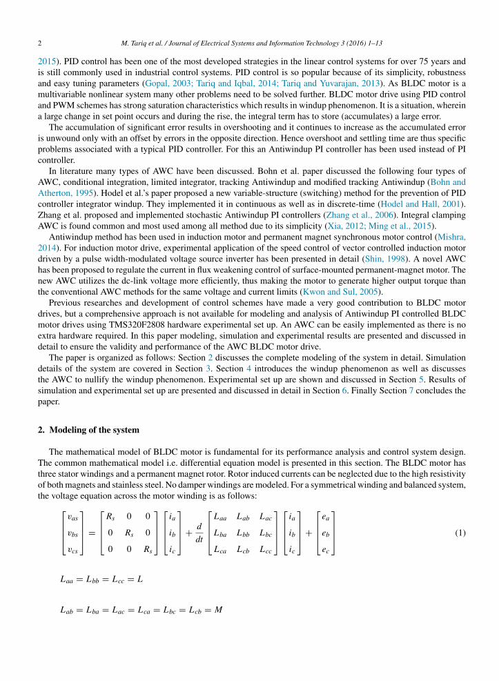
he function F(θ) gives the trapezoidal waveform of back EMF. One period of this function can be written as given inq. (12) and shown in Fig. 1.
F (θ) =
∣∣∣∣∣∣∣∣∣∣∣
1 0 < θ <2π
3
1 − 6
π
(θ − 2π
3
)2π
3< θ < π
5π
∣∣∣∣∣∣∣∣∣∣∣ (12)
∣∣∣∣∣∣−1 π < θ <3
−1 + 6
π
(θ + 5π
3
)5π
3< θ < 2π
∣∣∣∣∣∣
4 M. Tariq et al. / Journal of Electrical Systems and Information Technology 3 (2016) 1–13
-1.5
-1
-0.5
0
0.5
1
1.5
0 50 100 150 200 250 300 350 400 450F(Th
eta)
Theta
Fig. 1. The function for generating trapezoidal back EMF waveform.
3. Simulations in MATLAB/Simulink
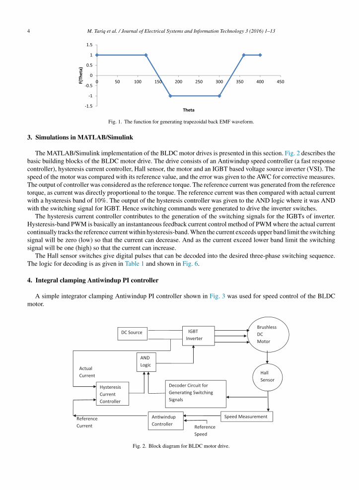
The MATLAB/Simulink implementation of the BLDC motor drives is presented in this section. Fig. 2 describes thebasic building blocks of the BLDC motor drive. The drive consists of an Antiwindup speed controller (a fast responsecontroller), hysteresis current controller, Hall sensor, the motor and an IGBT based voltage source inverter (VSI). Thespeed of the motor was compared with its reference value, and the error was given to the AWC for corrective measures.The output of controller was considered as the reference torque. The reference current was generated from the referencetorque, as current was directly proportional to the torque. The reference current was then compared with actual currentwith a hysteresis band of 10%. The output of the hysteresis controller was given to the AND logic where it was ANDwith the switching signal for IGBT. Hence switching commands were generated to drive the inverter switches.
The hysteresis current controller contributes to the generation of the switching signals for the IGBTs of inverter.Hysteresis-band PWM is basically an instantaneous feedback current control method of PWM where the actual currentcontinually tracks the reference current within hysteresis-band. When the current exceeds upper band limit the switchingsignal will be zero (low) so that the current can decrease. And as the current exceed lower band limit the switchingsignal will be one (high) so that the current can increase.
The Hall sensor switches give digital pulses that can be decoded into the desired three-phase switching sequence.The logic for decoding is as given in Table 1 and shown in Fig. 6.
4. Integral clamping Antiwindup PI controller
A simple integrator clamping Antiwindup PI controller shown in Fig. 3 was used for speed control of the BLDCmotor.
Reference Current
Actual Current
DC Source
Hall Senso r
Decoder Circuit for Gener a�ng Switc hing Signals
Hysteresis Current Controller
Brushless DC Motor
IGBT Inverter
AND Logic
Speed Measure ment An�windu p Controller Reference
Speed
Fig. 2. Block diagram for BLDC motor drive.

M. Tariq et al. / Journal of Electrical Systems and Information Technology 3 (2016) 1–13 5
Table 1Generation of switching sequence from Hall sensor signals.
Hall sensor signals Switching sequence for IGBT switches
H1 H2 H3 S1 (a+) S2 (a−) S3 (b+) S4 (b−) S5 (c+) S6 (c−)
1 0 0 1 0 0 1 0 01 0 1 0 0 0 1 1 00 0 1 0 1 0 0 1 00 1 1 0 1 1 0 0 00 1 0 0 0 1 0 0 11
ISbv
wC
P
5
Tf
twiL
1 0 1 0 0 0 0 1
It has a switch for selecting (or clamping) integrator gain. The output and input of the current limiter is compared.f input and output are equal then that means the controller has saturated and integrator action has to be switched off.imilarly the error and controlled output is also compared and if they are opposite in values then integrator has toe switched off. With the help of this logic we can avoid overshoot and can reduce settling time. The correspondingariable structure control law of the controller is
H = Ki.e if e.Cn > 0, Cn /= Cs (13)
H = 0 if e.Cn < 0, Cn = Cs (14)
here H = input to the integrator block; e = speed error; Cn = controlled output (before current limiter) ands = controlled output (after current limiter).
Figs. 2 and 3 were implemented in Simulink and a comparison study has been done between a PI and an AntiwindupI controller. The comparison results are shown in Figs. 7–12. The results are further tabulated in Table 3.
. Experimental validation
The hardware implementation of an Antiwindup PI controller for BLDC motor drive is discussed in this section.he simulation results for speed control are verified by the experimental results here. The parameters of the motor used
or experiment as well as simulation are given in Table 2.Commutation pulses were generated based on the information from Hall sensors and information were acquired
hrough the Texas Instrumentation DSP board (TMS320F2008). A three phase IGBT based intelligent power module
as used to commutate the phase currents. Hall effect current sensor was used for measuring the dc link current formplementing hysteresis current controller. For calculation of speed, the Hall sensor signal was given to F to V converterM 2907. The output of LM 2907 was recorded and discussed. Simple block diagram of experimental setup is shown
Fig. 3. A simple integrator clamping Antiwindup PI controller.
6 M. Tariq et al. / Journal of Electrical Systems and Information Technology 3 (2016) 1–13
Table 2Rating of BLDC motor.
Rated power 500 W
No. of poles 16No. of phases 3Type of connection StarDC voltage (Vs) 24 VRated current (I) 25 ARated speed 2500 rpmRated torque 1.9 N mResistance/phase 0.3 �
Self-inductance 2.5 mHMutual inductance 1.2 mHMoment of inertia 1271 × 10−7 kg m/s2
IGBT Inverter
Hall sensor
BLDC Motor
F to V converter
Oscilloscope DSP Board
PC
DC Source
Opto- couple r
Current Sensor and Signal Conditioner
PMDC Generator
Rheostat
Fig. 4. A simple structure diagram of experimental setup.
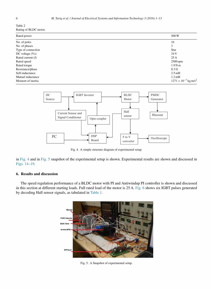
in Fig. 4 and in Fig. 5 snapshot of the experimental setup is shown. Experimental results are shown and discussed inFigs. 14–19.
6. Results and discussion
The speed regulation performance of a BLDC motor with PI and Antiwindup PI controller is shown and discussedin this section at different starting loads. Full rated load of the motor is 25 A. Fig. 6 shows six IGBT pulses generatedby decoding Hall sensor signals, as tabulated in Table 1.
Fig. 5. A Snapshot of experimental setup.

M. Tariq et al. / Journal of Electrical Systems and Information Technology 3 (2016) 1–13 7
Fig. 6. IGBT switching signals for 3 leg inverter.
s
s
Fig. 7. Speed response at 0% load starting.
In Fig. 7, results have been compared with no load condition. Using PI controller the overshoot is 275 rpm and
ettling time is 0.2 s, while with Antiwindup PI controller overshoot is only 75 rpm and settling time is only 0.07 s.In Fig. 8, results have been compared with 30% load condition. Using PI controller the overshoot is 225 rpm andettling time is 0.1 s, while with Antiwindup PI controller there is 0% overshoot and settling time is only 0.05 s.
Fig. 8. Speed response at 30% load starting.

8 M. Tariq et al. / Journal of Electrical Systems and Information Technology 3 (2016) 1–13
0 0.02 0.04 0.06 0.08 0.1 0.12 0.14 0.16 0.18 0.21000
1100
1200
1300
1400
1500
1600
1700Speed response for PI and AWC at 50% loads
Time in Seconds
Spe
ed in
RP
MConventional PI Controller,Overshoot 175 RPM (11.7%) Settling Time = 0.1 seconds
Antiwindup PI Controller, Overshoot 0 RPM ( 0 %) Settling Time = 0.07 seconds
Fig. 9. Speed response at 50% load starting.
0 0.1 0.2 0.3 0.4 0.5 0.6 0.71000
1100
1200
1300
1400
1500
1600
Time in Seconds
Spe
ed in
RP
M
Speed Responce for PI and AWC for 100 % Load (Full Load Starting)
Conventional PI Controller, Overshoot 25 RPM (1.7%),Settling Time = 0.6 seconds AntiWindup PI Controller, Overshoot 0 RPM (0%),Settling Time = 0.1 seconds
Fig. 10. Speed response at 100% load starting.
In Fig. 9, results have been compared for 50% load condition. Using PI controller the overshoot is 175 rpm andsettling time is 0.1 s, while with Antiwindup PI controller again there is no overshoot and settling time is only 0.06 s.
In Fig. 10, results have been compared for 100% load condition. Using PI controller the overshoot is 25 rpm andsettling time is 0.6 s, while with Antiwindup PI controller again there is no overshoot and settling time is only 0.1 s.
It can be observed from these figures that the Antiwindup PI controller has better anti disturbance ability, lessovershoot and less settling time of the system, and can improve the speed response ability. Moreover in Figs. 11 and 12the speed response of PI and AWC has been given to show the variations at different loads.
The comparison between PI and Antiwindup PI controller at different starting loads is also shown in Table 3. It canbe seen from the table as well as from Fig. 12, that the overshoot is zero for Antiwindup PI controller at 30%, 50%
Table 3Comparison between PI and Antiwindup PI controller at different starting loads.
Load at starting(% of rated load)
PI controller Antiwindup PI controller
Overshoot(rpm)
Overshoot(% of rated)
Settlingtime (s)
Overshoot(rpm)
Overshoot(% of rated)
Settlingtime (s)
0 275 18.3 0.2 75 5.0 0.0730 210 14.0 0.1 0 0.0 0.0550 175 11.7 0.1 0 0.0 0.06
100 25 1.7 0.6 0 0.0 0.1
M. Tariq et al. / Journal of Electrical Systems and Information Technology 3 (2016) 1–13 9
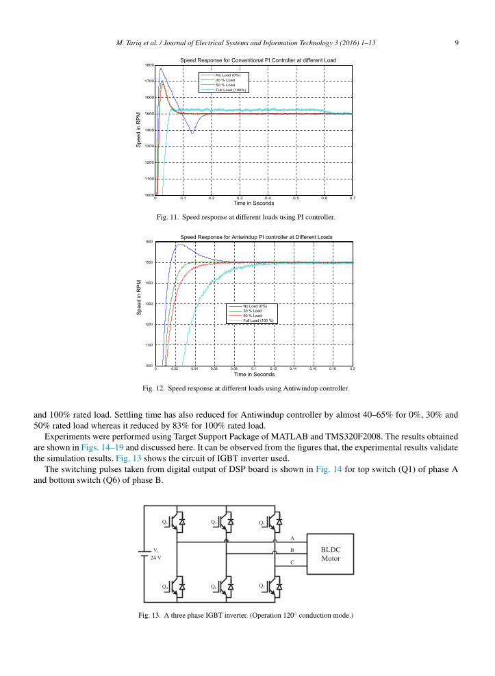
Fig. 11. Speed response at different loads using PI controller.
a5
at
a
Fig. 12. Speed response at different loads using Antiwindup controller.
nd 100% rated load. Settling time has also reduced for Antiwindup controller by almost 40–65% for 0%, 30% and0% rated load whereas it reduced by 83% for 100% rated load.
Experiments were performed using Target Support Package of MATLAB and TMS320F2008. The results obtainedre shown in Figs. 14–19 and discussed here. It can be observed from the figures that, the experimental results validatehe simulation results. Fig. 13 shows the circuit of IGBT inverter used.
The switching pulses taken from digital output of DSP board is shown in Fig. 14 for top switch (Q1) of phase And bottom switch (Q6) of phase B.
Fig. 13. A three phase IGBT inverter. (Operation 120◦ conduction mode.)

10 M. Tariq et al. / Journal of Electrical Systems and Information Technology 3 (2016) 1–13
Fig. 14. Switching pulse to IGBT inverter (to Q1 (Vap) and Q6 (Vbn) switches).
It can be observed from Fig. 14 that the switching pulses have variable ON period as it was generated by hysteresiscurrent controller. Whenever the current was exceeding 10% of the rated value, IGBT switches were getting OFF. Andwhenever the current was less than the rated value by more than 10%, then IGBT switches were getting ON.
For recording speed in oscilloscope, F to V converter was used. Hall sensor A signal was given to F to V converter.As BLDC motor has 16 poles, so frequency of Hall sensor A signal will be 8 times the frequency of the rotation ofrotor.
Speed of the motor is given by the relation N = 120f/P where f is the mechanical frequency.The comparison between simulation result and experimental result are shown in Figs. 15 and 16. In Fig. 15, 1
division corresponds to 4 V; therefore 6 divisions correspond 24 V. From F to V converter, for 67 Hz it will give 1 V,hence 24 V corresponds 1608 Hz. The frequency of Hall sensor A is 1608 Hz, hence mechanical frequency will be 8
times less i.e. 201 Hz. The speed corresponding to 201 Hz will be N = (120 × 201)/16 = 1507.5 rpm.Time taken for settling to reference speed for experimental system was 80 ms in Fig. 15, whereas for simulatedsystem it was 50 ms in Fig. 16.
Fig. 15. Experimental result (Antiwindup PI controller at 30% starting load) [settling time is 80 ms].
M. Tariq et al. / Journal of Electrical Systems and Information Technology 3 (2016) 1–13 11
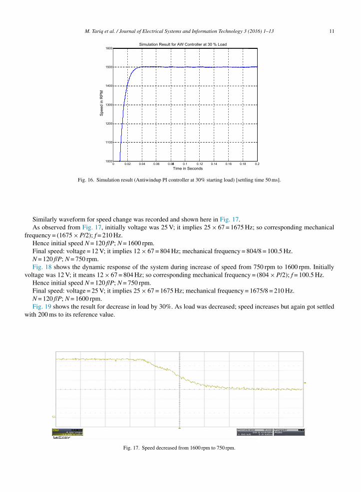
0 0.021000
1100
1200
1300
1400
1500
1600
Spe
ed in
RP
M
0.04 0.06 0.0 8
Simulation Result for AW Controller at 30 % Load
8 0.1 0.12Time in Seconds
0.14 0.16 0.18 0.2
Fig. 16. Simulation result (Antiwindup PI controller at 30% starting load) [settling time 50 ms].
f
v
w
Similarly waveform for speed change was recorded and shown here in Fig. 17.As observed from Fig. 17, initially voltage was 25 V; it implies 25 × 67 = 1675 Hz; so corresponding mechanical
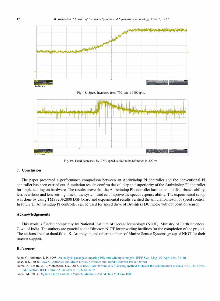
requency = (1675 × P/2); f = 210 Hz.Hence initial speed N = 120 f/P; N = 1600 rpm.Final speed: voltage = 12 V; it implies 12 × 67 = 804 Hz; mechanical frequency = 804/8 = 100.5 Hz.N = 120 f/P; N = 750 rpm.Fig. 18 shows the dynamic response of the system during increase of speed from 750 rpm to 1600 rpm. Initially
oltage was 12 V; it means 12 × 67 = 804 Hz; so corresponding mechanical frequency = (804 × P/2); f = 100.5 Hz.Hence initial speed N = 120 f/P; N = 750 rpm.Final speed: voltage = 25 V; it implies 25 × 67 = 1675 Hz; mechanical frequency = 1675/8 = 210 Hz.N = 120 f/P; N = 1600 rpm.Fig. 19 shows the result for decrease in load by 30%. As load was decreased; speed increases but again got settled
ith 200 ms to its reference value.
Fig. 17. Speed decreased from 1600 rpm to 750 rpm.
12 M. Tariq et al. / Journal of Electrical Systems and Information Technology 3 (2016) 1–13
Fig. 18. Speed increased from 750 rpm to 1600 rpm.
Fig. 19. Load decreased by 30%, speed settled to its reference in 200 ms.
7. Conclusion
The paper presented a performance comparison between an Antiwindup PI controller and the conventional PIcontroller has been carried out. Simulation results confirm the validity and superiority of the Antiwindup PI controllerfor implementing on hardware. The results prove that the Antiwindup PI controller has better anti disturbance ability,less overshoot and less settling time of the system, and can improve the speed response ability. The experimental set upwas done by using TMS320F2808 DSP board and experimental results verified the simulation result of speed control.In future an Antiwindup PI controller can be used for speed drive of Brushless DC motor without position sensor.
Acknowledgements
This work is funded completely by National Institute of Ocean Technology (NIOT), Ministry of Earth Sciences,Govt. of India. The authors are grateful to the Director, NIOT for providing facilities for the completion of the project.The authors are also thankful to K. Arumugam and other members of Marine Sensor Systems group of NIOT for theirintense support.
References
Bohn, C., Atherton, D.P., 1995. An analysis package comparing PID anti-windup strategies. IEEE Syst. Mag. 15 (April (2)), 34–40.
Bose, B.K., 2006. Power Electronics and Motor Drives Advances and Trends. Elsevier Press, Oxford.Darba, A., De Belie, F., Melkebeek, J.A., 2015. A back-EMF threshold self-sensing method to detect the commutation instants in BLDC drives.Ind. Electron. IEEE Trans. 62 (October (10)), 6064–6075.Gopal, M., 2003. Digital Control and State Variable Methods, 2nd ed. Tata McGraw Hill.

HKKK
L
MMM
SS
T
T
T
T
VXZ
M. Tariq et al. / Journal of Electrical Systems and Information Technology 3 (2016) 1–13 13
odel, A.S., Hall, C.E., 2001. Variable structure for PID control to prevent integrator windup. IEEE Trans. Ind. Appl. 48 (2), 803–813.rishnan, R., 2001. Electric Motor Drives: Modeling, Analysis and Control, 1st ed. Prentice Hall.rishnan, R., 2010. Permanent Magnet Synchronous and Brushless DC Motor Drives. Taylor and Francis.won, T.S., Sul, S.K., 2005. Novel Antiwindup of a current regulator of a surface-mounted permanent-magnet motor for flux-weakening control.
In: Industry Applications Conference, 3, Hong Kong, pp. 1813–1819.ajoie-Mazenc, M., Villanueva, C., Hector, J., 1985. Study and implementation of a hysteresis controlled inverter on a permanent magnet synchronous
machine. IEEE Trans. Ind. Appl. IA-21 (2), 408–413.iller, T.J.E., 1989. Brushless Permanent Magnet & Reluctance Motor Drives, vol. 2. Clarendon Press, Oxford.ing, Y., Tang, S., Xu, D., 2015. Comments on Antiwindup strategy for PI-type speed controller. Ind. Electron. IEEE Trans. 62 (2), 1329–1332.ishra, P., 2014. Design and implementation of speed controller with anti-windup scheme for three phase induction motor used in electric vehicle.
Int. J. Comput. Appl. 89 (9).hin, H.B., 1998. New anti-windup PI controller for variable speed motor drives. IEEE Trans. Ind. Electron. 45 (June (3)), 445–450.on, Y.I., In Hyuk, K., Choi, D.S., Shim, H., 2015. Robust cascade control of electric motor drives using dual reduced-order PI observer. Ind.
Electron. IEEE Trans. 62 (June (6)), 3672–3682.ariq, M., Iqbal, M.T., 2014. Power quality improvement by using multi-pulse AC–DC converters for DC drives: modeling, simulation and its digital
implementation. J. Electr. Syst. Inf. Technol. 1 (3), 255–265.ariq, M., Varshney, N., Dhilsha, R., 2013. Simulation and performance evaluation of position sensor and sensorless based speed control of BLDC
motor using hysteresis band PWM current controller. Elixir Int. J. Electr. Eng. 61 (8), 16778–16781.ariq, M., Varshney, N., 2014. Digital simulation and analysis of six modes of operation of BLDC motor drives using hysteresis band PWM switching
scheme. Int. J. Energy Power Eng. 3 (2), 57–64.ariq, M., Yuvarajan, S., 2013. Modeling and analysis of self excited induction generator with electronic load controller supplying static loads. Can.
J. Electr. Electron. Eng. 4 (1), 9–13.
enkatratnam, K., 2009. Special Electrical Machines. Universities Press India Pvt. Ltd.ia, C.-L., 2012. Permanent Magnet Brushless DC Motor Drives and Controls, 1st ed. Wiley Science Press.hang, D., Li, H., Collins, E.G., 2006. Digital anti-windup PI controllers for variable-speed motor drives using FPGA and stochastic theory. PowerElectron. IEEE Trans. 21 (September (5)), 1496, 1501.