
Fast Hard and Soft Shadow Generation on Complex Models ...gamma.cs.unc.edu/SRT/techreport.pdf ·...
9
Fast Hard and Soft Shadow Generation on Complex Models using Selective Ray Tracing UNC CS Technical Report TR09-004, January 2009 Christian Lauterbach ∗ University of North Carolina at Chapel Hill Qi Mo † University of North Carolina at Chapel Hill Dinesh Manocha ‡ University of North Carolina at Chapel Hill Figure 1: Soft shadows: Our algorithm can render the 12.7M tri- angle Powerplant model at 16 fps with hard shadows (left) and over 2 fps with soft shadows with 16 light samples (right) running on a NVIDIA GTX 280 GPU. Abstract We present fast algorithms to generate high-quality hard and soft shadows in complex models. Our method combines the efficiency of rasterization-based shadow mapping approaches with the accu- racy of a ray tracer based on conservative image space bounds. The algorithm can handle moving light sources as well as dynamic scenes. In practice, our approach is able to generate shadows on CAD and scanned models composed of millions of triangles at close to interactive rates on current high-end GPUs. 1 Introduction The state of the art in interactive rendering is constantly moving to- wards greater physical realism and detail. This is primarily driven by the rapid increase in performance provided by commodity GPUs which are able to utilize parallelism along with high coherence in memory accesses and computations to rasterize models with mil- lions of triangles at interactive rates. However, one of the chal- lenges is generating images with high-quality hard and soft shad- ows. Many rasterization-based approaches can be used to generate shadows, but when evaluating them on large, complex models they typically can only provide either high performance or accuracy, but not both. On the other hand, ray tracing provides a simple solution to generate accurate hard and soft shadows with good scalability for large in-core models [Foley and Sugerman 2005; Günther et al. 2007]. Despite recent advances and good use of parallelism, cur- rent ray tracing implementations are one or two orders of magnitude slower than rasterization approaches on GPUs. Shadow volumes can be used to generate high-quality hard and soft shadows, but their complexity can increase considerably with ∗ e-mail: [email protected] † e-mail:[email protected] ‡ e-mail:[email protected] model complexity and number of silhouette edges. The fastest techniques for hard shadows are based on regular shadow maps, which are well supported by current rasterization hardware. How- ever, these algorithms can suffer from aliasing errors. It is possible to overcome these errors by using hybrid combinations of shadow maps and shadow volumes [Chan and Durand 2004] or using irreg- ular shadow mapping [Aila and Laine 2004; Johnson et al. 2005]. However, these algorithms may not scale well to complex models composed of millions of triangles and are limited to hard shadow generation. Main results: In this paper, we present a selective ray tracing algo- rithm to generate accurate hard and soft shadows on current many- core GPUs. Our approach is general and the overall image quality is comparable to that of a fully ray-traced shadow generation al- gorithm. Moreover, the algorithm can efficiently handle complex models, as long as the model and its bounding volume hierarchy can fit into the GPU memory. Our hybrid formulation performs conservative rasterization based on shadow mapping techniques and identifies the regions or the pix- els of the frame (called PIP) that are potentially inaccurate due to under-sampling in light space or missed primitives due to rasteriza- tion errors. We use selective ray tracing to compute correct shading information only for those pixels in PIP, as described in Section 3. We also present an efficient technique for coupling with a GPU ray tracer to provide the missing information for those pixels. In ad- dition, our approach extends very easily to area light sources and can be used to generate high-quality stochastic soft shadows. In practice, the subset of inaccurate pixels is small and our approach shoots relatively few rays as compared to a full ray tracer, resulting in a significant speedup. The notion of performing hybrid shadow generation based on con- servative rasterization is not new. As compared to prior hybrid ap- proaches, our algorithm offers the following advantages: • High-quality shadows: In our complex benchmark scenes the hard and soft shadow generation algorithms result in almost no perspective or projective aliasing artifacts. • Efficiency: We use compact hierarchical representations to accelerate ray intersections and allow ray tracing on GPUs with low memory overhead. As compared to pure shadow mapping, our hybrid algorithms are only 30-70% slower, but about 4 − 10 times faster than full ray tracing. • Hardware utilization: Our approach maps directly onto cur- rent GPUs and needs no special hardware support or changes to existing architectures. It uses less memory bandwidth than full ray tracing and its performance should increase with the growth rate of future GPUs, as described in Section 4. We demonstrate our implementation on several models ranging from game-like scenes with dynamic objects to massive CAD mod- els with millions of triangles at interactive rates on a high-end GPU, as described in Section 5.
Transcript of Fast Hard and Soft Shadow Generation on Complex Models ...gamma.cs.unc.edu/SRT/techreport.pdf ·...

Fast Hard and Soft Shadow Generation on Complex Models using Selective Ray
Tracing
UNC CS Technical Report TR09-004, January 2009
Christian Lauterbach∗
University of North Carolina at Chapel Hill
Qi Mo†
University of North Carolina at Chapel Hill
Dinesh Manocha‡
University of North Carolina at Chapel Hill
Figure 1: Soft shadows: Our algorithm can render the 12.7M tri-angle Powerplant model at 16 fps with hard shadows (left) and over2 fps with soft shadows with 16 light samples (right) running on aNVIDIA GTX 280 GPU.
Abstract
We present fast algorithms to generate high-quality hard and softshadows in complex models. Our method combines the efficiencyof rasterization-based shadow mapping approaches with the accu-racy of a ray tracer based on conservative image space bounds.The algorithm can handle moving light sources as well as dynamicscenes. In practice, our approach is able to generate shadows onCAD and scanned models composed of millions of triangles atclose to interactive rates on current high-end GPUs.
1 Introduction
The state of the art in interactive rendering is constantly moving to-wards greater physical realism and detail. This is primarily drivenby the rapid increase in performance provided by commodity GPUswhich are able to utilize parallelism along with high coherence inmemory accesses and computations to rasterize models with mil-lions of triangles at interactive rates. However, one of the chal-lenges is generating images with high-quality hard and soft shad-ows. Many rasterization-based approaches can be used to generateshadows, but when evaluating them on large, complex models theytypically can only provide either high performance or accuracy, butnot both. On the other hand, ray tracing provides a simple solutionto generate accurate hard and soft shadows with good scalabilityfor large in-core models [Foley and Sugerman 2005; Günther et al.2007]. Despite recent advances and good use of parallelism, cur-rent ray tracing implementations are one or two orders of magnitudeslower than rasterization approaches on GPUs.
Shadow volumes can be used to generate high-quality hard andsoft shadows, but their complexity can increase considerably with
∗e-mail: [email protected]†e-mail:[email protected]‡e-mail:[email protected]
model complexity and number of silhouette edges. The fastesttechniques for hard shadows are based on regular shadow maps,which are well supported by current rasterization hardware. How-ever, these algorithms can suffer from aliasing errors. It is possibleto overcome these errors by using hybrid combinations of shadowmaps and shadow volumes [Chan and Durand 2004] or using irreg-ular shadow mapping [Aila and Laine 2004; Johnson et al. 2005].However, these algorithms may not scale well to complex modelscomposed of millions of triangles and are limited to hard shadowgeneration.
Main results: In this paper, we present a selective ray tracing algo-rithm to generate accurate hard and soft shadows on current many-core GPUs. Our approach is general and the overall image qualityis comparable to that of a fully ray-traced shadow generation al-gorithm. Moreover, the algorithm can efficiently handle complexmodels, as long as the model and its bounding volume hierarchycan fit into the GPU memory.
Our hybrid formulation performs conservative rasterization basedon shadow mapping techniques and identifies the regions or the pix-els of the frame (called PIP) that are potentially inaccurate due tounder-sampling in light space or missed primitives due to rasteriza-tion errors. We use selective ray tracing to compute correct shadinginformation only for those pixels in PIP, as described in Section 3.We also present an efficient technique for coupling with a GPU raytracer to provide the missing information for those pixels. In ad-dition, our approach extends very easily to area light sources andcan be used to generate high-quality stochastic soft shadows. Inpractice, the subset of inaccurate pixels is small and our approachshoots relatively few rays as compared to a full ray tracer, resultingin a significant speedup.
The notion of performing hybrid shadow generation based on con-servative rasterization is not new. As compared to prior hybrid ap-proaches, our algorithm offers the following advantages:
• High-quality shadows: In our complex benchmark scenes thehard and soft shadow generation algorithms result in almostno perspective or projective aliasing artifacts.
• Efficiency: We use compact hierarchical representations toaccelerate ray intersections and allow ray tracing on GPUswith low memory overhead. As compared to pure shadowmapping, our hybrid algorithms are only 30-70% slower, butabout 4−10 times faster than full ray tracing.
• Hardware utilization: Our approach maps directly onto cur-rent GPUs and needs no special hardware support or changesto existing architectures. It uses less memory bandwidth thanfull ray tracing and its performance should increase with thegrowth rate of future GPUs, as described in Section 4.
We demonstrate our implementation on several models rangingfrom game-like scenes with dynamic objects to massive CAD mod-els with millions of triangles at interactive rates on a high-end GPU,as described in Section 5.

UNC CS Technical Report TR09-004, January 2009
Hierarchy
Geometry
Framebuffer(s) unshaded FB with pixels marked
Open ray buffer Traced ray results
FB shaded with ray results
PIP detectionRay generation
and compactionRay tracing Shading
Rasterization
Figure 2: Overview: Pipeline model of our hybrid rendering algorithm. After GPU-based rasterization is run, the PIP computation detectsand marks pixels that need to be ray traced. The ray generation step generates a dense ray list from the sparse buffer of potentially incorrectpixels and then generates one or more rays per pixels as required. A selective ray tracer traces all the rays using the scene hierarchy andthen applies the results to the original buffer. Finally, the pixels are shaded based on the ray results.
2 Previous work
We give a brief overview of related work limited to interactiveshadow generation and reducing aliasing errors and refer the read-ers to [Hasenfratz et al. 2003; Lloyd 2007; Laine 2006] for recentsurveys on shadow algorithms.
Hard shadows: At a broad level, prior techniques to alleviatealiasing artifacts using rasterization methods are based on shadowmaps [Williams 1978] and shadow volumes [Crow 1977]. Somehybrid approaches have been proposed that combine shadow map-ping and volumes [McCool 2000; Chan and Durand 2004] that canimprove shadow volume performance and allow interactive high-quality shadows on simple scenes. Most current interactive applica-tions use variants of shadow mapping, but may suffer from aliasingproblems. Many practical algorithms have been proposed to allevi-ate perspective aliasing [Stamminger and Drettakis 2002; Wimmeret al. 2004; Lloyd 2007] as well as projective aliasing [Lefohn et al.2007]. Other shadow mapping algorithms can eliminate blockingartifacts [Aila and Laine 2004; Johnson et al. 2005] by implement-ing a rasterizer that can process arbitrary samples on the imageplane.
Soft shadows: In general, soft shadows can be implemented bysample-based methods such as using averaging visibility from mul-tiple shadow maps to calculate visibility or ray tracing. Both thesemethods can be slow, so many approaches have been developed togenerate plausible soft shadows with methods such as post-filteringshadow maps or special camera models [Mo et al. 2007], whichproduce correct results only for simple scenes. More accurate ap-proaches evaluate the light source visibility from the image samplesby back-projection [Assarsson and Akenine-Möller 2003; Schwarzand Stamminger 2007; Sintorn et al. 2008; Bavoil et al. 2008] or bygenerating shadows from environment lighting [Annen et al. 2008].Techniques using irregular z-buffering have also been extended forsoft shadows on a proposed new architecture [Johnson et al. 2009].
3 Shadows using selective ray tracing
In this section, we present our algorithms for generating high qual-ity shadows based on hybrid rendering and selective ray tracing.The main idea behind selective ray tracing is to only shoot rays cor-responding to a small subset of the pixels in the final image in orderto accelerate overall rendering. Our assumption is that we have un-derlying fast rasterization algorithms such as shadow mapping thatcompute the correct result for most of the frame, but may includelocalized error such as aliasing artifacts in parts of the image. Wetry to identify these regions of potentially incorrect pixels (PIP) ina conservative manner, since any additionally selected pixels willnot change the image whereas missed ones may result in artifacts.As Fig. 2 illustrates, this is a multi-step process that starts with theresults of a GPU shadow algorithm that provides a first approxi-
mation to the desired result. As a next step, we test the accuracyof each pixel and classify it accordingly, marking some pixels inthe buffer as potentially incorrect. The buffer with all marked andunmarked pixels is then passed into the ray tracer where the firststep filters out all non-marked pixels and keeps just the potentiallyincorrect pixels in a compact, non-sparse form. For each pixel inthe PIP set, we shoot one or more rays to compute the correct vis-ibility or shading information for the shadows. All rays are storedin a dense list that can be used as input for any data parallel, many-core GPU ray tracer. After the rays have been evaluated, the resultsare then written back to the original pixels in the PIP set. Back inthe rasterizer, a shading kernel is used to compute colors for all thepixels.
3.1 Hard shadows
Shadow mapping is one of the most widely used algorithms forgenerating hard shadows for interactive applications. It works ongeneral, complex 3D static and dynamic scenes and maps well ontocurrent GPUs. However, the shadow maps may need high reso-lution to avoid aliasing artifacts. These errors can be classifiedinto perspective and projective aliasing [Stamminger and Drettakis2002]. Perspective error occurs due to the position of the surfacewith respect to the light and viewpoint and result in the ’blocki-ness’ of shadows in the algorithm. Projective error stems from theorientation of the receiver to light and viewpoint. Geometric errorsfrom under-sampling can also include missing contributions fromobjects that are too small or thin in light space, e.g. surfaces thatare oriented close to coplanar with the view direction. Artifactsfrom this error result in missing and interrupted shadows for theseobjects. Finally, shadow map self-shadowing error occurs from in-accuracies in the depth values computed in the light view and thecamera view. It stems both from depth buffer precision (numeri-cal error) as well as orientation of the surface (geometric error). Weconsider this mainly an artifact that can be minimized by increasingdepth precision and using slope-dependent bias and do not addressit directly in our algorithm.
Pixel classification: We now discuss our method for estimating theset of pixels in the image that can potentially be incorrect (PIP)due to the error described above. We first note that most of theerror in shadow mapping appears at shadow boundaries while theshadow interiors (as well as the interiors of lit regions) tend to beaccurate. Thus, we can assume that when we look up the corre-sponding sample in the shadow map for a given image sample, itshould not be considered accurate if it is adjacent to an edge inthe shadow map. We therefore modify the standard depth bufferlook-up to test the 8 texels around the sample value with depths in the shadow map and find the maximum absolute difference∆ = max(‖s − s′‖,s′ ∈ depth around S) in depth. If ∆ exceeds athreshold value, e.g. a fraction of the possible scene depth as de-termined by z-buffer near and far planes, we assume that there is ashadow edge at this image pixel. In this case, we need to make sure

UNC CS Technical Report TR09-004, January 2009
S
n
L
XX
S
S
X
a) b)
= shadow map sample = image sample
XX
SS
c) d)
X
X
S
n
Figure 3: PIP computation: a) For a given image sample X weproject back to the shadow map and find the corresponding sampleS. We then test the depths of the surrounding shadow map samplesand select the one with the maximum difference ∆ in depth value toS and label it as S. b) We now determine whether the surface at X
can be affected by an edge at S and S by finding the closest point X
on the surface within the angle α of one shadow map pixel and find
its depth d. c) If d is within the shaded region of depth ∆ around S
or on the other side of the region as seen from X, then it needs to beray traced. In this case, the pixel can be classified as shadowed. d)Counter-example: X is in the region and thus the pixel is ray traced.
this edge can affect the shadow generation at the current shadingsample X that is at distance d from the light source (see Fig. 3.1 forillustration.) This is to prevent that a relatively small shadow dis-continuity at one side of the model does still affect pixels far away.To achieve this, we find the closest distance to the light d that thereceiver surface can reach within the angle α of one texel of theshadow map. Intuitively, the closer to parallel the receiver surfaceis to the light direction, the larger the difference between d and d
becomes. If d overlaps the interval [s−∆,s + ∆] or d and d are ondifferent sides of S then we mark the pixel as part of the PIP set.
The actual computation of d for a local point light source followsfrom trigonometry such that d = d sinβ/sinα +β . Given the nor-mal vector n and normalized light direction L, then this is easilycomputed by using sinβ = n ·L. A similar calculation for direc-tional lights is relatively straightforward. Note that is also possibleto precompute ∆ for the shadow map and store it for each pixel inaddition to the depth value. This may be useful if the light source ismostly static since it reduces the memory bandwidth needed duringthe lighting pass of the rasterization algorithm.
One case that the method above does not detect is the geometricaliasing problem when a primitive is too small (e.g. a thin wire)as seen from the light view and thus not even drawn during scan-line rendering. Some of the pixels that are actually covered by theobject may not get rasterized and thus not detected during edge fil-tering. This can cause missing shadows regions in the actual image.Our solution is to identify these small objects during rasterizationfrom the light view and employ conservative rendering techniquesto assure that they are actually part of the PIP set. We use geometryshaders to implement the conservative triangle rendering methoddescribed in [Hasselgren et al. 2005] and modified by [Sintorn et al.2008]. In essence, each triangle is transformed into a polygon with6 corners by extruding at the original vertices. The new extrudedprimitive is then guaranteed to cover the center point of each pixelthat it touches. Since extending all the triangles in the scene couldbe extremely costly, the shader also tests the area and aspect ratioof each triangle in image space and only uses conservative render-ing for those that are thin and thus likely to be missed. At the same
Figure 4: Detecting shadow artifacts: Shadow on City model.
Top left: shadows with shadow mapping at 20482 resolution. TopRight: pixels marked for ray tracing in red. Bottom left: pixelsmarked by conservative rendering. Bottom right: final result. Theimage is identical to the fully ray-traced result.
time, this technique automatically avoids very small but regular tri-angles (e.g. as in scanned models) where conservative rendering isnot needed. Note that an even more efficient culling method woulddetect whether the triangle also has a silhouette edge, but we foundthat this adds more constraints on the rendering pipeline by havingto provide adjacency information. Figure 4 illustrates the effect ofour conservative rendering approach.
3.2 Soft shadows
We now describe an extension of the approach presented above thatcan also be used to render high quality soft shadows. Ray tracingapproaches commonly stochastically generate a number of sampleson the area light source for each hit point, evaluate their visibilityusing shadow rays and then average the results to find an estimateof how much of the light source is visible from the hit point. How-ever, a high number of samples and shadow rays are needed to avoidhigh frequency aliasing error. We observe that the only area thatneeds to be evaluated from multiple light samples is the penumbraregion, because for umbra and fully lit regions the visibility of thelight is binary. This enables us to handle those binary regions usingrasterization-based techniques, e.g. shadow mapping, and to iden-tify the penumbra as potentially incorrect pixels (PIP), and therebyperform selective ray tracing on these pixels. They only correspondto a portion of the final image, so significant amount of computa-tion can be saved. More importantly, ray-based computation can bedirected to regions that need it the most.
One standard shadow map taken from the center of the light sufficesfor our approach to estimate the penumbra region. For pixels in theimage plane that do not fall in our estimated penumbra no shadowrays are needed and they will be shaded by shadow mapping. Thepenumbra is identified in the following manner. First we computeedge pixels in the shadow map in the same way we do for hardshadows. For hard shadows those edge pixels are the potentiallyinaccurate pixels, while for soft shadows they need to be expandedto account for the effect of the area light sources. Next we computethe projection of the area light onto the shadow map, centered ateach of these silhouette pixels. This is equivalent to splatting eachedge pixel using the shape of the light and a size based on the depthdifference between the light and the edge. After splatting all theedge pixels we get a mask which is a union of all the splats in themap. Masked pixels are potentially in penumbra while unmaskedpixels are either in the umbra or fully lit. We use this in a sim-ilar way as a shadow map. During rendering any points that areprojected inside the masked area belong to the estimated penumbra

UNC CS Technical Report TR09-004, January 2009
Figure 5: Penumbra classification: Soft shadow on Bunny model.Left: mask in the shadow map formed by splatting edge pixels. Mid-dle: penumbra pixels marked for ray tracing in red. Right: finalresult.
and are ray traced using multiple shadow rays (e.g. 8×8 sampling),while points that are projected inside unmasked area are classifiedas umbra or fully lit based on the original shadow map. Figure 5shows an example of this process.
The advantage of this approach is that it estimates the penumbrawith the cost of little more than a standard shadow map, and con-sequently large parts of the image can be exempted from shadowray tracing. Admittedly not all silhouette edges can be captured be-cause the shadow map is generated only from the center of the light,but because such missed edges are often in the vicinity of the edgesthat are actually identified, it is very likely that most of the penum-bra regions in the final image plane have been correctly identified.The accuracy can be further improved by computing shadow mapsfrom multiple samples on the area light source, e.g. the corners,and then computing the union of masked pixels from each.
4 Analysis and Comparison
4.1 Comparison
A very important aspect for evaluation of our algorithm is the dif-ference in image quality compared to the full ray tracing solution.We present a detailed comparison for several benchmark scenes inthe appendix that show the original image generated with shadowmapping at 10242 resolution, selective ray tracing results and ref-erence full ray tracing (with a difference image). In practice, forhard shadows we have observed that our algorithm computes im-ages that are almost error free and virtually identical to fully raytraced results for all our benchmark scenes, with differences arisingfrom biasing errors. Unfortunately, we cannot guarantee full cor-rectness since some features such as very small holes inside a solidobject could theoretically be missed due to the regular sampling inlight space (i.e. geometric aliasing errors). However, these artifactsappear to be very rare.
It is hard to directly compare the quality of our results with onlyrasterization-based approaches. The fast shadow mapping meth-ods based on warping and partitioning may not account for pro-jective aliasing [Stamminger and Drettakis 2002; Wimmer et al.2004; Lloyd 2007] and their accuracy can vary based on the rela-tive position of the light source w.r.t. the viewpoint. Many tech-niques to handle projective aliasing [Lefohn et al. 2007] and alias-free shadow maps [Aila and Laine 2004; Johnson et al. 2005] canbe implemented on current GPUs. These approaches can generatehigh quality shadows, but it is not clear whether they can scale wellto massive models. For soft shadows, most of the accurate meth-ods may not be able to handle complex models at interactive rateson current processors. Recently, Sintorn et al. [2008] presenteda soft shadow algorithm that can handle models with at most tensof thousands of triangles at interactive rates. It uses a more accu-rate method for penumbra computation, but its scalability on largemodels with moving light sources is not clear.
Our hybrid approach shares the same theme as other hybrid shadowgeneration algorithms that use shadow polygons and LODs [Govin-
Model Geometry Full RT SRT SRT+SM SRT % Rays
City 2 MB 1066 MB 113 MB 222 MB 5
Sibenik 2.2 MB 2280 MB 224 MB 859 MB 4
Buddha 27 MB 3148 MB 601 MB 1144 MB 12
Figure 6: Memory bandwidth: Simulated memory bandwidth re-
quirements for rendering one frame at 5122 image resolution withselective (SRT) and full ray tracing (FRT) on several models (totalstorage for geometry and BVH is given in second column to showthe total working set size.) The last column shows the time for SRplus a very conservative estimation of bandwidth needed by scan-line rendering of the shadow map.
daraju et al. 2003] or shadow volumes [Chan and Durand 2004].However, LODs can affect the accuracy of the shadow boundaries.Moreover, the complexity of shadow volumes tense to increase withthe number of silhouette edges in complex models. Thus, the bottle-neck becomes the fill rate needed for rendering all volumes, whichbecomes prohibitively large with high geometric complexity. Theanalysis in [McGuire 2004] shows that the overall expected num-ber of silhouette edges for a model is proportional to the sum ofthe dihedral angles. As an example, the average dihedral angle perprimitive on Powerplant model is about 6 times the average angleon the Buddha model. Based on our experiments with several view-points, over 4 million silhouette edges may need to be rendered perframe for shadow volumes on Powerplant. The hybrid method in[Chan and Durand 2004] uses shadow mapping and employs a sim-ple discontinuity detection on the depth map, then performs selec-tive rasterization for the marked pixels using hierarchical z-culling.However, hybrid shadow volumes still have significant drawbackscompared to our approach. First, generating and processing the vol-umes including silhouette computation can be expensive especiallyfor large CAD models with complex topology such the models usedhere. Second, even though shadow volumes may need to be selec-tively rasterized for only a small set of pixels, all shadow volumesstill have to be processed by the rendering pipeline in any case.Hierarchical culling in the hardware may cull areas of the imageefficiently, but the hybrid approach will most likely decrease the ef-ficiency of the GPU rasterizer since active pixels will be relativelysparse and the parallel rasterization units are not sufficiently utilizedby rendering only a few pixels inside a block of pixels. Finally,our approach provides a much improved algorithm for detectingwhether depth continuities actually affect each pixel, thus reducingthe number of pixels ray traced on complex models, while our con-servative rendering approach detects contributions from small ob-jects that would be missed by the previously described approaches.
4.2 Performance analysis
In this section, we show that our hybrid algorithm maps to currentmany-core GPUs and has lower memory bandwidth requirementsas compared to full ray tracing. A key issue in designing GPGPU orrelated algorithms on current highly parallel architectures is to en-sure that they are not limited by memory bandwidth. This is mainlybecause the growth rate for computational power far exceeds thatof memory bandwidth. The streaming model of computation usedin the rasterization pipeline has been shown to be very successfulin this regard with memory bandwidth being mostly used for depthand frame buffer accesses.
We analyzed the memory bandwidth requirements when runningboth selective and full ray tracing for two of our benchmark models,in particular the memory bandwidth used by the actual ray tracingkernel. Since current GPU architectures have limited cache sizes,i.e. only a texture cache, such analysis is simpler than for CPUs.We implemented a simple software simulator that emulates the be-havior of the memory unit for global memory accesses in CUDAin device emulation mode running on the host CPU. Care has to be
UNC CS Technical Report TR09-004, January 2009
05
101520253035404550
1000000 2000000 4000000 8000000
Pe
rfo
rma
nce
FP
S
#triangles
Hard shadows
Soft shadows (16x)
0
2
4
6
8
10
12
14
16
0123456789
10
0 5 10 15 20
% p
ixe
ls r
ay
tra
ced
Re
lati
ve
pe
rfo
rma
nce
Light source area
Performance
% pixels
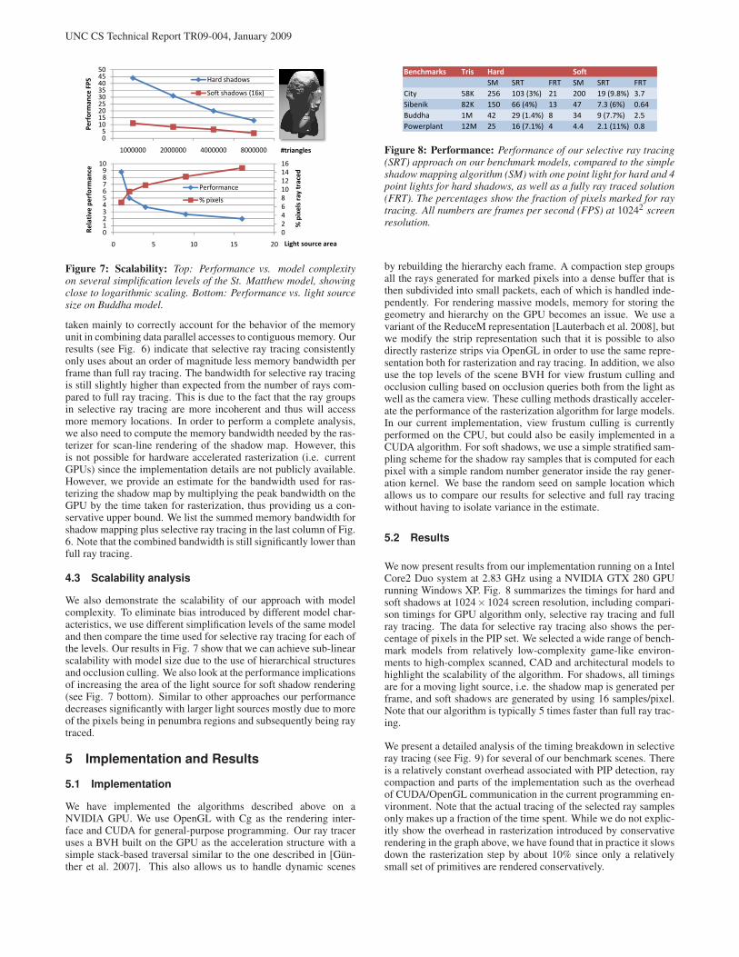
Figure 7: Scalability: Top: Performance vs. model complexityon several simplification levels of the St. Matthew model, showingclose to logarithmic scaling. Bottom: Performance vs. light sourcesize on Buddha model.
taken mainly to correctly account for the behavior of the memoryunit in combining data parallel accesses to contiguous memory. Ourresults (see Fig. 6) indicate that selective ray tracing consistentlyonly uses about an order of magnitude less memory bandwidth perframe than full ray tracing. The bandwidth for selective ray tracingis still slightly higher than expected from the number of rays com-pared to full ray tracing. This is due to the fact that the ray groupsin selective ray tracing are more incoherent and thus will accessmore memory locations. In order to perform a complete analysis,we also need to compute the memory bandwidth needed by the ras-terizer for scan-line rendering of the shadow map. However, thisis not possible for hardware accelerated rasterization (i.e. currentGPUs) since the implementation details are not publicly available.However, we provide an estimate for the bandwidth used for ras-terizing the shadow map by multiplying the peak bandwidth on theGPU by the time taken for rasterization, thus providing us a con-servative upper bound. We list the summed memory bandwidth forshadow mapping plus selective ray tracing in the last column of Fig.6. Note that the combined bandwidth is still significantly lower thanfull ray tracing.
4.3 Scalability analysis
We also demonstrate the scalability of our approach with modelcomplexity. To eliminate bias introduced by different model char-acteristics, we use different simplification levels of the same modeland then compare the time used for selective ray tracing for each ofthe levels. Our results in Fig. 7 show that we can achieve sub-linearscalability with model size due to the use of hierarchical structuresand occlusion culling. We also look at the performance implicationsof increasing the area of the light source for soft shadow rendering(see Fig. 7 bottom). Similar to other approaches our performancedecreases significantly with larger light sources mostly due to moreof the pixels being in penumbra regions and subsequently being raytraced.
5 Implementation and Results
5.1 Implementation
We have implemented the algorithms described above on aNVIDIA GPU. We use OpenGL with Cg as the rendering inter-face and CUDA for general-purpose programming. Our ray traceruses a BVH built on the GPU as the acceleration structure with asimple stack-based traversal similar to the one described in [Gün-ther et al. 2007]. This also allows us to handle dynamic scenes
Benchmarks Tris Hard Soft
SM SRT FRT SM SRT FRT
City 58K 256 103 (3%) 21 200 19 (9.8%) 3.7
Sibenik 82K 150 66 (4%) 13 47 7.3 (6%) 0.64
Buddha 1M 42 29 (1.4%) 8 34 9 (7.7%) 2.5
Powerplant 12M 25 16 (7.1%) 4 4.4 2.1 (11%) 0.8
Figure 8: Performance: Performance of our selective ray tracing(SRT) approach on our benchmark models, compared to the simpleshadow mapping algorithm (SM) with one point light for hard and 4point lights for hard shadows, as well as a fully ray traced solution(FRT). The percentages show the fraction of pixels marked for raytracing. All numbers are frames per second (FPS) at 10242 screenresolution.
by rebuilding the hierarchy each frame. A compaction step groupsall the rays generated for marked pixels into a dense buffer that isthen subdivided into small packets, each of which is handled inde-pendently. For rendering massive models, memory for storing thegeometry and hierarchy on the GPU becomes an issue. We use avariant of the ReduceM representation [Lauterbach et al. 2008], butwe modify the strip representation such that it is possible to alsodirectly rasterize strips via OpenGL in order to use the same repre-sentation both for rasterization and ray tracing. In addition, we alsouse the top levels of the scene BVH for view frustum culling andocclusion culling based on occlusion queries both from the light aswell as the camera view. These culling methods drastically acceler-ate the performance of the rasterization algorithm for large models.In our current implementation, view frustum culling is currentlyperformed on the CPU, but could also be easily implemented in aCUDA algorithm. For soft shadows, we use a simple stratified sam-pling scheme for the shadow ray samples that is computed for eachpixel with a simple random number generator inside the ray gener-ation kernel. We base the random seed on sample location whichallows us to compare our results for selective and full ray tracingwithout having to isolate variance in the estimate.
5.2 Results
We now present results from our implementation running on a IntelCore2 Duo system at 2.83 GHz using a NVIDIA GTX 280 GPUrunning Windows XP. Fig. 8 summarizes the timings for hard andsoft shadows at 1024×1024 screen resolution, including compari-son timings for GPU algorithm only, selective ray tracing and fullray tracing. The data for selective ray tracing also shows the per-centage of pixels in the PIP set. We selected a wide range of bench-mark models from relatively low-complexity game-like environ-ments to high-complex scanned, CAD and architectural models tohighlight the scalability of the algorithm. For shadows, all timingsare for a moving light source, i.e. the shadow map is generated perframe, and soft shadows are generated by using 16 samples/pixel.Note that our algorithm is typically 5 times faster than full ray trac-ing.
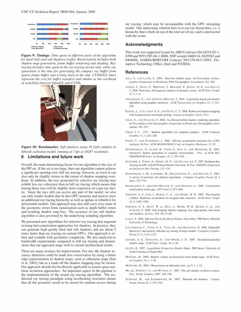
We present a detailed analysis of the timing breakdown in selectiveray tracing (see Fig. 9) for several of our benchmark scenes. Thereis a relatively constant overhead associated with PIP detection, raycompaction and parts of the implementation such as the overheadof CUDA/OpenGL communication in the current programming en-vironment. Note that the actual tracing of the selected ray samplesonly makes up a fraction of the time spent. While we do not explic-itly show the overhead in rasterization introduced by conservativerendering in the graph above, we have found that in practice it slowsdown the rasterization step by about 10% since only a relativelysmall set of primitives are rendered conservatively.
UNC CS Technical Report TR09-004, January 2009
0% 20% 40% 60% 80% 100%
City
Sibenik
Buddha
Powerplant
Shadow mapping Ray TracingRay organization CUDA/GL overhead
0% 20% 40% 60% 80% 100%
City
Sibenik
Buddha
Powerplant
Figure 9: Timings: Time spent in different parts of the algorithmfor hard (left) and soft shadows (right). Rasterization includes bothshadow map generation, frame buffer rendering and shading. Raytracing includes time spent in the ray tracing kernel only, while raygeneration is the time for generating the compact ray buffer fromsparse frame buffer and writing back at the end. CUDA/GL timesrepresent the cost for buffer transfers and similar as the overheadof switching between OpenGL and CUDA.
Figure 10: Benchmarks: Soft shadows using 16 light samples in
Sibenik cathedral model, running at 7 fps at 10242 resolution.
6 Limitations and future work
Overall, the main determining factor for our algorithm is the size ofthe PIP set. If the set is too large, then our algorithm cannot achievea significant speedup over full ray tracing; however, at worst it canalso only be slightly slower to the extent of shadow mapping over-head. In addition, the rays generated by selective ray tracing mayexhibit less ray coherence than in full ray tracing which means thattracing these rays will be slightly more expensive on a per-ray met-ric. Since the rays still can access any part of the model, we alsocan only render models that fit into GPU memory and need to storean additional ray tracing hierarchy as well as update or rebuild it fordeformable models. Our approach may also still carry over some ofthe geometric errors from rasterization such as depth buffer errorsand resulting shadow map bias. The accuracy of our soft shadowalgorithm is also governed by the underlying sampling algorithm.
We presented new algorithms for selective ray tracing that augmentexisting fast rasterization approaches for shadows. In practice, theycan generate high-quality hard and soft shadows and are about 5times faster than ray tracing on current GPUs. Our approach is ro-bust and scalable with geometric complexity. We also analyzed itsbandwidth requirements compared to full ray tracing and demon-strate that our approach maps well to current architectural trends.
There are many avenues for improvement. For one, the shadow ac-curacy detection could be made less conservative by using a betteredge representation in shadow maps, such as silhouette maps [Senet al. 2003], but as a trade-off the shadow mapping may be slower.Our approach should also be directly applicable to screen-space am-bient occlusion approaches. An important aspect in the pipeline isthe implementation of the actual ray tracing algorithm. The tra-ditional ray tracing paradigm using accelerating structures meansthat all the geometry needs to be stored for random access during
ray tracing, which may be incompatible with the GPU streamingmodel. One interesting solution here is to use ray hierarchies, i.e. ahierarchy that is built on top of the total set of rays and is intersectedwith the scene.
Acknowledgments
This work was supported in part by ARO Contracts DAAD19-02-1-0390 and W911NF-04-1-0088, NSF awards 0400134, 0429583 and0404088, DARPA/RDECOM Contract N61339-04-C-0043, Dis-ruptive Technology Office, Intel and NVIDIA.
References
AILA, T., AND LAINE, S. 2004. Alias-free shadow maps. In Proceedings of Euro-
graphics Symposium on Rendering 2004, Eurographics Association, 161–166.
ANNEN, T., DONG, Z., MERTENS, T., BEKAERT, P., SEIDEL, H.-P., AND KAUTZ,J. 2008. Real-time, all-frequency shadows in dynamic scenes. ACM Trans. Graph.
27, 3, 1–8.
ASSARSSON, U., AND AKENINE-MÖLLER, T. 2003. A geometry-based soft shadowalgorithm using graphics hardware. ACM Transactions on Graphics 22, 3, 511–520.
BAVOIL, L., CALLAHAN, S. P., AND SILVA, C. T. 2008. Robust soft shadow mappingwith backprojection and depth peeling. Journal of Graphics Tools 13(1).
CHAN, E., AND DURAND, F. 2004. An efficient hybrid shadow rendering algorithm.In Proceedings of the Eurographics Symposium on Rendering, Eurographics Asso-ciation, 185–195.
CROW, F. C. 1977. Shadow algorithms for computer graphics. ACM Computer
Graphics 11, 3, 242–248.
FOLEY, T., AND SUGERMAN, J. 2005. KD-tree acceleration structures for a GPUraytracer. In Proc. ACM SIGGRAPH/EG Conf. on Graphics Hardware, 15–22.
GOVINDARAJU, N., LLOYD, B., YOON, S., SUD, A., AND MANOCHA, D. 2003.Interactive shadow generation in complex environments. Proc. of ACM SIG-
GRAPH/ACM Trans. on Graphics 22, 3, 501–510.
GÜNTHER, J., POPOV, S., SEIDEL, H.-P., AND SLUSALLEK, P. 2007. Realtime RayTracing on GPU with BVH-based Packet Traversal. In Proc. IEEE/EG Symposium
on Interactive Ray Tracing, 113–118.
HASENFRATZ, J.-M., LAPIERRE, M., HOLZSCHUCH, N., AND SILLION, F. 2003.A survey of real-time soft shadows algorithms. Computer Graphics Forum 22, 4(dec), 753–774.
HASSELGREN, J., AKENINE-MÖLLER, T., AND OHLSSON, L. 2005. Conservativerasterization on the gpu. GPU Gems 2, 677–690.
JOHNSON, G. S., LEE, J., BURNS, C. A., AND MARK, W. R. 2005. The irregularz-buffer: Hardware acceleration for irregular data structures. ACM Trans. Graph.
24, 4, 1462–1482.
JOHNSON, G. S., HUNT, W. A., HUX, A., MARK, W. R., BURNS, C. A., AND
JUNKINS, S. 2009. Soft irregular shadow mapping: fast, high-quality, and robustsoft shadows. In Proc. I3D ’09, 57–66.
LAINE, S. 2006. Efficient Physically-Based Shadow Algorithms. PhD thesis, HelsinkiUniversity of Technology.
LAUTERBACH, C., YOON, S.-E., TANG, M., AND MANOCHA, D. 2008. ReduceM:Interactive and memory efficient ray tracing of large models. Computer Graphics
Forum 27, 4, 1313–1321.
LEFOHN, A. E., SENGUPTA, S., AND OWENS, J. D. 2007. Resolution-matchedshadow maps. ACM Trans. Graph. 26, 4, 20.
LLOYD, B. 2007. Logarithmic Perspective Shadow Maps. PhD thesis, University ofNorth Carolina at Chapel Hill.
MCCOOL, M. 2000. Shadow volume reconstruction from depth maps. ACM Trans.
on Graphics 19, 1, 1–26.
MCGUIRE, M. 2004. Observations on silhouette sizes. jgt 9, 1, 1–12.
MO, Q., POPESCU, V., AND WYMAN, C. 2007. The soft shadow occlusion camera.Proc. Pacific Graphics 2007, 189–198.
SCHWARZ, M., AND STAMMINGER, M. 2007. Bitmask soft shadows. Comput.
Graph. Forum 26, 3, 515–524.

UNC CS Technical Report TR09-004, January 2009
SEN, P., CAMMARANO, M., AND HANRAHAN, P. 2003. Shadow silhouette maps.ACM Transactions on Graphics (Proceedings of ACM SIGGRAPH 2003) 22, 3(July), 521–526.
SINTORN, E., EISEMANN, E., AND ASSARSSON, U. 2008. Sample-based visibilityfor soft shadows using alias-free shadow maps. Computer Graphics Forum (Proc.
EGSR ’07) 27, 4, 1285–1292.
STAMMINGER, M., AND DRETTAKIS, G. 2002. Perspective shadow maps. In Proc.
SIGGRAPH ’02, 557–562.
WILLIAMS, L. 1978. Casting curved shadows on curved surfaces. In Computer
Graphics (SIGGRAPH ’78 Proceedings), vol. 12, 270–274.
WIMMER, M., SCHERZER, D., AND PURGATHOFER, W. 2004. Light space per-spective shadow maps. In Proc. of the Eurographics Symposium on Rendering,143–152.

UNC CS Technical Report TR09-004, January 2009
Shadow mapping Our approach Ray traced Difference image
(e) 256 FPS (f) 103 FPS (g) 21 FPS (h) Difference
(i) 150 FPS (j) 66 FPS (k) 13 FPS (l) Difference
(m) 42 FPS (n) 29 FPS (o) 8 FPS (p) Difference
(q) 25 FPS (r) 16 FPS (s) 4 FPS (t) Difference
Figure 11: Hard shadows: We compare the image fidelity of our algorithm to a pure ray-traced reference solution. From left to right:
shadow mapping at 10242, selective ray tracing, ray traced reference, difference selective to reference.

UNC CS Technical Report TR09-004, January 2009
Shadow mapping Our approach Ray traced Difference image
(e) 200 FPS (f) 19 FPS (g) 3.9 FPS (h) Difference
(i) 47 FPS (j) 7.3 FPS (k) 0.64 FPS (l) Difference
(m) 34 FPS (n) 9 FPS (o) 2.5 FPS (p) Difference
(q) 4.4 FPS (r) 2.1 FPS (s) 0.8 FPS (t) Difference
Figure 12: Soft shadows: We compare the image fidelity of our algorithm to a pure ray-traced reference solution . From left to right: shadow
mapping with 4 samples at 10242, selective ray tracing, ray traced reference (both at 16 samples/pixel), difference selective to reference.