FAST FACTORIZED BACK-PROJECTION IN AN FPGA237459/FULLTEXT01.pdfThe Fast Factorized Back Projection...
67
Technical report, IDE0607, January 2006 FAST FACTORIZED BACK-PROJECTION IN AN FPGA Master Thesis report in Electrical Engineering 1 and Computer Systems Engineering 2 Andreas Hast 1 Lars Johansson 2 School of Information Science, Computer and Electrical Engineering Halmstad University
Transcript of FAST FACTORIZED BACK-PROJECTION IN AN FPGA237459/FULLTEXT01.pdfThe Fast Factorized Back Projection...

Technical report, IDE0607, January 2006
FAST FACTORIZEDBACK-PROJECTION IN AN FPGA
Master Thesis report in Electrical Engineering1
and
Computer Systems Engineering2
Andreas Hast1 Lars Johansson2
School of Information Science, Computer and Electrical Engineering
Halmstad University


Fast Factorized Back-Projection in an FPGA
Master Thesis report in Electrical Engineering1
and
Computer Systems Engineering2
School of Information Science, Computer and Electrical EngineeringHalmstad University
Box 823, S-301 18 Halmstad, Sweden
Jan 2006
c© 2006Andreas Hast1 Lars Johansson2
All Rights Reserved

FAST FACTORIZED BACK-PROJECTION IN AN FPGA
Description of cover page picture: Aircraft equiped with CARABAS(Photo Pia Ericsson, FMV)
ii

Preface
This thesis is the final part of the master’s degree at the University of Halmstad. Duringthe thesis we have had a lot of good discussions and help from our supervisor AndersAhlander. We would like to thank Annelie Wyholt (PHD student at Chalmers universityof technology) for providing us with the Matlab file for simulating the CARABAS systemoutput. We would also like to thank Ulf Blixt for reading our report and giving us feedbackon the grammatical and spelling in the report.
————————— —————————Andreas Hast Lars Johansson
Halmstad University, 20th January 2006
iii

FAST FACTORIZED BACK-PROJECTION IN AN FPGA
iv

Abstract
The Fast Factorized Back Projection (FFBP) algorithm is a computationally efficientalgorithm for image formation in a Very High Frequency Synthetic Aperture Radar (VHFSAR) system. In this report an investigation of the feasibility of using an FPGA with ahard CPU core to calculate the FFBP in real-time has been done. Two System on a Chipdesigns for this task have been proposed for calculating the FFBP. A simplified version ofthe FFBP has also been implemented in Matlab and used during this project. The resultis that the computationally intensive parts, such as index generating and interpolationcalculations, should be implemented in the logic part of the FPGA and the CPU shouldhandle scheduling. This kind of modular system is easy to maintain and upgrade.
v

FAST FACTORIZED BACK-PROJECTION IN AN FPGA
vi

Abbreviations
AASR Associative Aperture Synthesis Radar
BP Back-Projection
CERES Centre for Research on Embedded Systems
CPU Central Processing Unit
DFT Discrete Fourier Transform
DPB Direct Back-Projection
DSP Digital Signal Processor
FBP Factorized Back Projection
FFBP Fast Factorized Back-Projection
FFT Fast Fourier Transform
FPGA Field Programmable Gate Arrays
GBP Global Back Projection
GUI Graphical User Interface
HDL Hardware Description Language
ILS Instrument Landing System
IP Intellectual Property
ISE Integrated Software Environment
OPB On-chip Peripheral Bus
PLB Processor Local Bus
PRF Pulse Repetition Frequency
PRI Ping Repetition Interval
RADAR RAdio Detection And Ranging
SAR Synthetic Aperture Radar
SAS Synthetic Aperture Sonar
SIMD Single Instruction Multiple Data
vii

FAST FACTORIZED BACK-PROJECTION IN AN FPGA
SoC System on a Chip
VHF Very High Frequency
UAV Unmanned Aerial Vehicle
XPS Xilinx Platform Studio
viii
LIST OF FIGURES
List of Figures
2.1 Shows the pulse period and the pulse width. . . . . . . . . . . . . . . . . . . 6
2.2 Ambiguity problems caused by too high PRF. . . . . . . . . . . . . . . . . . 7
2.3 Pulse compression and matched filters. . . . . . . . . . . . . . . . . . . . . . 8
2.4 The returning echoes from a pulse are stored in a range bin. . . . . . . . . . 9
2.5 An echo matrix is built up by range bins. . . . . . . . . . . . . . . . . . . . 9
2.6 Three different SAR methods: Stripmap, scan and spotlight. . . . . . . . . . 10
2.7 Phase difference to target point P of different pulses depends on ∆r. . . . . 11
3.1 The relationship between aperture angles iteration number. . . . . . . . . . 15
3.2 Shows the data focusing in-between iterations. . . . . . . . . . . . . . . . . . 16
3.3 Geometric relationship in FFBP. . . . . . . . . . . . . . . . . . . . . . . . . 17
4.1 A system overview on a large scale. . . . . . . . . . . . . . . . . . . . . . . . 19
4.2 Development board from Memec . . . . . . . . . . . . . . . . . . . . . . . . 19
4.3 The system flow for calculationg the cells/pixels. . . . . . . . . . . . . . . . 20
4.4 A proposed system solution. . . . . . . . . . . . . . . . . . . . . . . . . . . . 21
4.5 A proposed system solution. . . . . . . . . . . . . . . . . . . . . . . . . . . . 22
5.1 Raw radar data from five points. . . . . . . . . . . . . . . . . . . . . . . . . 24
5.2 GBP on the radar data shown in Figure 5.1 (not the same scale) . . . . . . 24
5.3 Second iteration, here data focusing starts to become clear. . . . . . . . . . 25
5.4 Sixth and last iteration. . . . . . . . . . . . . . . . . . . . . . . . . . . . . . 26
5.5 Shows how the real data becomes stretched and pulled when plotted. . . . . 26
5.6 The real number errors. . . . . . . . . . . . . . . . . . . . . . . . . . . . . . 27
5.7 Imaginary part error (with strage effects) . . . . . . . . . . . . . . . . . . . 28
ix

FAST FACTORIZED BACK-PROJECTION IN AN FPGA
x

CONTENTS
Contents
1 Introduction 1
1.1 Goal of the thesis . . . . . . . . . . . . . . . . . . . . . . . . . . . . . . . . 1
1.1.1 Engineering complexity . . . . . . . . . . . . . . . . . . . . . . . . . 2
1.1.2 Scalability . . . . . . . . . . . . . . . . . . . . . . . . . . . . . . . . 2
1.1.3 Performance . . . . . . . . . . . . . . . . . . . . . . . . . . . . . . . 2
1.1.4 Portability . . . . . . . . . . . . . . . . . . . . . . . . . . . . . . . . 2
1.2 FPGA vs. DSP/CPU technologies . . . . . . . . . . . . . . . . . . . . . . . 2
2 Introduction to RADAR 5
2.1 Choice of frequency . . . . . . . . . . . . . . . . . . . . . . . . . . . . . . . 5
2.2 Radar operation . . . . . . . . . . . . . . . . . . . . . . . . . . . . . . . . . 6
2.3 Resolution . . . . . . . . . . . . . . . . . . . . . . . . . . . . . . . . . . . . 7
2.4 Pulse compression . . . . . . . . . . . . . . . . . . . . . . . . . . . . . . . . 7
2.5 SAR Synthetic Aperture Radar . . . . . . . . . . . . . . . . . . . . . . . . 8
2.6 SAR Geometry . . . . . . . . . . . . . . . . . . . . . . . . . . . . . . . . . 11
2.7 Algorithms . . . . . . . . . . . . . . . . . . . . . . . . . . . . . . . . . . . . 11
2.8 Existing systems . . . . . . . . . . . . . . . . . . . . . . . . . . . . . . . . 12
2.8.1 AASR - Associative Aperture Synthesis Radar . . . . . . . . . . . . 12
2.8.2 Forestry . . . . . . . . . . . . . . . . . . . . . . . . . . . . . . . . . 12
2.8.3 SAS - Synthetic Aperture Sonar . . . . . . . . . . . . . . . . . . . . 13
3 FFBP - Fast Factorized Back-Projection 15
3.1 How does the algorithm work? . . . . . . . . . . . . . . . . . . . . . . . . . 15
4 Implementation 19
4.1 Hardware . . . . . . . . . . . . . . . . . . . . . . . . . . . . . . . . . . . . 19
4.2 Software . . . . . . . . . . . . . . . . . . . . . . . . . . . . . . . . . . . . . 20
4.3 Architectural proposal . . . . . . . . . . . . . . . . . . . . . . . . . . . . . 20
4.4 SoC Design . . . . . . . . . . . . . . . . . . . . . . . . . . . . . . . . . . . 20
4.5 Support programs tested . . . . . . . . . . . . . . . . . . . . . . . . . . . . 22
xi

FAST FACTORIZED BACK-PROJECTION IN AN FPGA
5 Results 23
5.1 Matlab simulations . . . . . . . . . . . . . . . . . . . . . . . . . . . . . . . 23
5.2 Error due to rounding . . . . . . . . . . . . . . . . . . . . . . . . . . . . . 26
5.3 Time to calculate the FFBP . . . . . . . . . . . . . . . . . . . . . . . . . . 28
6 Conclusion and discussion 31
6.1 Engineering complexity . . . . . . . . . . . . . . . . . . . . . . . . . . . . . 31
6.2 Scalability . . . . . . . . . . . . . . . . . . . . . . . . . . . . . . . . . . . . 31
6.3 Performance . . . . . . . . . . . . . . . . . . . . . . . . . . . . . . . . . . . 32
6.4 Portability . . . . . . . . . . . . . . . . . . . . . . . . . . . . . . . . . . . . 32
6.5 Discussion . . . . . . . . . . . . . . . . . . . . . . . . . . . . . . . . . . . . 32
6.6 Future Work . . . . . . . . . . . . . . . . . . . . . . . . . . . . . . . . . . . 33
Bibliography 35
A Appendix 37
B Appendix 41
C Appendix 45
D Appendix 53
xii

CHAPTER 1. INTRODUCTION
1 Introduction
The CARABAS II system is using the Very High Frequency (VHF) band together withthe Synthetic Aperture Radar (SAR) technology to create maps over large areas witha resolution in the order of the wavelength. The advantage of using this low frequencyis that small objects don’t reflect the radio waves. This means that the radio wavespenetrates treetops, foliage and other small objects, and thus sees what is under there.This has great potential in both military and civilian areas [1]. The military use of sucha radar is quite obvious, to detect enemy vehicles hiding in forest areas.
When using VHF-SAR big tree stems and other large objects work as corner reflectors.By theory and observation it has been proven that the strength of the reflected echo isproportional to the tree stems volume. By calculating these echo’s one can make a goodestimation of the amount of trees in the area. Then by changing the polarisation of theradar waves calculations on the branch volume can be done to some extent [2].
The algorithms used to create these maps are very time consuming to process and havebeen extremely hard to implement in real time. This has led to that all processing ofdata has been done on the ground ”off line”. One of the goals in the next generation SARsystem is to create the radar maps on the plane in real time. This triggered the need ofreal time solutions of the algorithms used and this thesis work will investigate the FastFactorized Back-Projection (FFBP) algorithm and how it can be implemented in an FieldProgrammable Gate Arrays (FPGA) to meet this problem.
The rest of this chapter will discuss the goal and different aspects of the goal. It alsocontains a small comparison between FPGA and DSP/CPU technologies. To give thereaders who do not have a basic understanding of radar, an introduction to radar is givenin chapter two. The chapter FFBP - Fast Factorized Back-Projection a more detailedexplanation of the FFBP algorithm is done. In the chapter Implementation, hard- andsoftware of the proposed system is explained, there is also a more detailed explanation ofthe architectural proposals. In chapter five the results are presented. The sixth chaptercontains conclusion and discussion.
1.1 Goal of the thesis
The goal of this thesis project is to investigate the feasibility of implementing the FFBP al-gorithm on an FPGA with an embedded hard Central Processing Unit (CPU). If feasable,how efficient will it be with regards to performance. This thesis is part of an ongoing re-search between Centre for Research on Embedded Systems (CERES) group at the Halm-stad University and Ericsson Microwave Systems AB in Molndal. The thesis was proposedby CERES to give a basic and further understanding of the combination of radar algo-rithms and FPGAs. There are many aspects that have to be taken in to considerationduring this work. The different aspects are discussed below.
1

FAST FACTORIZED BACK-PROJECTION IN AN FPGA
1.1.1 Engineering complexity
How difficult is it for engineers in the field to understand and modify the implementationto fit future needs e.g. tuning algorithms? Will it be easy to upgrade and implementnew functionality? Building a system that is easy to understand and modify can be veryhard to implement. One good example of this is mathematical operations with floatingand fixed point numbers. It is relatively easy to work and calculate with floating pointnumbers, but the hardware implementation gets more complex and hard to implement.
1.1.2 Scalability
How does the problem scale? Can future updates be done easily? The system mayand most certainly will be used with different types of aircrafts. An Unmanned AerialVehicle (UAV) is not able to carry the same weight as a larger plane. How can the designgrow when more die area of future hardware platforms is available? In which dimension(s)can the problem be scaled, e.g. can the FFBP be scaled over more than one FPGA?
1.1.3 Performance
The CARABAS system is designed to fit in an airplane with limited performance, withregards to e.g. carrying weight and generating power. Will the computational performanceachieved, given the constraints, be enough to calculate the algorithms in real time onboard the plane? The environment in an aircraft can be very harsh with vibrations asone example. Since this problem has a more physical nature it will not be taken intoconsideration in this thesis.
1.1.4 Portability
Is it possible to transfer the design to different architectures e.g. FPGA solutions fromdifferent manufacturers? A problem with FPGA designs is the fact that the solutionstend to be very dependent on the architecture on a low level. It will be very hard to evenget close to the level of portability that is achieved using a CPU design. However keepingthis aspect in mind the designers can try to maximize the portability. If the efficiency isof high importance the design might be forced to set the portability priority lower [3].
All these aspects must be taken into consideration when the system design and the al-gorithms are built up and chosen. All aspects are of course important. The scalabilityand the engineering complexity are always good to have in mind since that probably willaffect the result and significance of the work.
1.2 FPGA vs. DSP/CPU technologies
Using an FPGA approach to process data can give certain advantages over traditionalCPU based designs. Implementing an algorithm in hardware which is designed and opti-mized for one task can reduce execution times and keep the power consumption at a lowlevel.
2

CHAPTER 1. INTRODUCTION
Ex. Multiplication
If a lot of multiplications needs to be done, a DSP/CPU would be able to do the numberof multiplications per cycle that the parallel part would allow. This would mean thatsome kind of loop is needed to calculate large matrices, but an FPGA with multipliers isable to do the number of multiplications equal to the number multipliers per cycle.
But a DSP/CPU can be very efficient when running control loops and complex branches,if this was to be implement on an FPGA, the logic needed to do the same task wouldprobably use up most of the logic space of the FPGA, and the data rate would probablynot be as efficient [4].
The ability of the FPGA technologies increases with Moore’s law and the most powerfulFPGAs of today have many abilities, e.g. embedded memory and CPU cores. Theseabilities can be used to implement whole System on Chip designs and in that way createflexible solutions to a wide variety of tasks. A drawback using FPGAs instead of aDSP/CPU in a new system is that it can be very difficult to port an algorithm fromC/Assembler to an Hardware Description Language (HDL) so that the area of the FPGAis used in an efficient way. This means that it can become very difficult to squeeze out allpotential performance out of the device [3].
The FPGA based signal processing engines have the benefit of not having to do theload/store and instruction-fetch commands that traditional von Neumann DSP/CPUshave to do. An FPGA-based system can achieve true parallel processing by executing thealgorithm(s) in the parallel way that they are based on [5].
3

FAST FACTORIZED BACK-PROJECTION IN AN FPGA
4

CHAPTER 2. INTRODUCTION TO RADAR
2 Introduction to RADAR
In this chapter the basic concepts of Radar such as choice of frequency, resolution, pulsecompression, SAR-Radar and existing systems are explained.
Radar which means RAdio Detection And Ranging uses electro magnetic radio wavesto detect targets and determine at what range the target is. Radar is an active systemmeaning that it is independent of other radiation sources than the one in the system. Thesystem works by sending out a pulse of energy and when the pulse reaches an object,parts of the signal will be reflected back to the radar antenna. Radio signals travel at aconstant speed close to the speed of light. Knowing the speed of the signal, the range canbe calculated by measuring the time it takes for the signal to travel from the transceiverback to the receiver. The energy reflected back is given by the radar equation (2.1).
SignalEnergy =PavgGσAetot
R4(4π)2(2.1)
Pavg is the average transmitted power, G is the antenna gain, σ is the radar cross sectionof the target, Ae is the antenna efficiency, R is the range to the target, tot is time thetarget is illuminated, the longer the target is illuminated the more energy will be reflectedback to the receiver. Noticeable in this equation is that the strongest factor in expressionis the range that is decreasing the signal energy with 1/R4 [6].
2.1 Choice of frequency
When choosing the frequency that the radar is going to use, some things are needed tobe taken into consideration. First the hardware size is proportional to the wave length.A hardware with larger dimensions manages to send out more power, which increasesthe detection range. The width of the main lobe is determined by the wavelength andthe size of the antenna. When using larger wave lengths the antenna has to be largerto achieve a certain width of the main lobe. One thing that has to be considered thenis the kind of object the radar will detect. Objects of different sizes reflect and absorbvarious frequencies differently. To avoid detection of small objects, one have to choosea wave length that is much larger than the objects. The CARABAS system operates atfrequencies from 20 to 90 MHz; this produces a wave length of about 3-15 meters. Thisallows the system to see through leaves and small branches in a forest, because only stemsand objects on the ground give reflection [7]. If the interest is in weather, a better choiceof frequency might lie around 5 GHz to match the refraction index of water. If the radaris going to operate on clouds, the frequency has to be even higher. The frequency has tobe about 14 GHz due to the small water drops in the cloud. When choosing the frequency,consideration to other frequencies that are already in use have to be taken into accounte.g. TV and radio broadcasts. Both of these applications lie in the operation rangeof the CARABAS system which can cause problems due to their strong power output
5

FAST FACTORIZED BACK-PROJECTION IN AN FPGA
of the transmitters. Other transmissions that can be disturbed by the signals from theCARABAS system are the signals from the Instrument Landing System (ILS) system atairports. The ILS is used for guiding airplanes when landing, and it is important not tointerfere with these kinds of systems [6].
2.2 Radar operation
To avoid that transmitted and receiving pulses do not interfere, the radar transmits thesignal in pulses with the pulse width τ and a period of T Figure 2.1.This is more commonlyexpressed with Pulse Repetition Frequency (PRF), which is illustrated by (2.2).
PRF =1
T(2.2)
Figure 2.1: Shows the pulse period and the pulse width.
With a low PRF, the detection range becomes higher but as said earlier, the energy of thesignal is reduced by R4 (where R is the range to the target). To give the signal enoughpower to detect objects at a long range, the amplitude of the pulse or the duty factor ofthe radar has to be increased. The duty factor is expressed by (2.3).
Dutyfactor =τ
T(2.3)
If the PRF is too high, ambiguity in the range echo’s can appear, this will make a distantobject seem closer. The targets will appear closer due to that the echo received will beseen at T + t and then appear at a distance proportional to t, Figure 2.2 [6].
6

CHAPTER 2. INTRODUCTION TO RADAR
Figure 2.2: Ambiguity problems caused by too high PRF.
If the PRF is too low, some ambiguity may appear with the Doppler frequencies. Thisbecause of that the phasors have moved more than one revolution on the unit circle, andif this happens the radar will misinterpret the speed of the target [6].
2.3 Resolution
Resolution which is defined as the smallest distance between two targets where bothobjects still can be discerned, have two different forms namely distance- and azimuthresolution. The resolution in distance is determined by the length of the pulse. Afterreflection the echoes from every object have to be separated from each other. If the pulselength is too large the echoes from two objects will be detected as one. The azimuthresolution is determined by the lobe width of the antenna at a certain distance. The lobewidth is calculated by the wavelength divided by the physical size of the antenna. Toobtain a high azimuth resolution you have to either choose a high frequency or have awide antenna [6].
2.4 Pulse compression
One way to attain a better distance resolution is to make a pulse compression on the signal;the most commonly used pulse compression is the Chirp-pulse or linear pulse compression.The chirp pulse is created by increasing the frequency over time. When using a matchedfilter on the chirp pulse the signal becomes shorter with higher amplitude, which makesit possible to separate two chirp signals from each other Figure 2.3 [6].
7

FAST FACTORIZED BACK-PROJECTION IN AN FPGA
Figure 2.3: Pulse compression and matched filters.
2.5 SAR Synthetic Aperture Radar
SAR which stands for ”Synthetic Aperture Radar” is one of the most sophisticated engi-neering inventions of the 20-th century. SAR-radar can either be mounted on an airplaneor satellite to take high resolution images of terrain. SAR have been around since 1950,but due to the lack of computer power and advanced digital signal processing algorithmsthe SAR system could not be used in an efficient way [8].
Compression can be used to obtain a high resolution in distance pulse, but for highazimuth resolution SAR is a good method to be used.
An example: Azimut resolution (∆a) for an antenna.
In order to image an area one km (R) away, utilizing a one meter (D) antenna, with awave length of 50 cm (λ ), the resolution will be 500 m [2]:
∆a =R ∗ λ
D(2.4)
Now if the antenna instead was one km long the resolution would become 50 cm.
But building a one km long antenna is an impossible task. However if the radar insteadwas to be moved along a one km synthetic straight line where it sends and receives echoesalong the whole synthetic line one would have a one km synthetic radar.
When storing the echo, the exact position from where the echo came from is not known,only the range and the lobe width is known. This is done for every pulse, and this togetherwith digital signal processing algorithms is later processed to obtain a high resolutionimage, as shown in Figure 2.4 [6].
8

CHAPTER 2. INTRODUCTION TO RADAR
Figure 2.4: The returning echoes from a pulse are stored in a range bin.
The range bins are then put together into echo matrices, Figure 2.5.
Figure 2.5: An echo matrix is built up by range bins.
For this method to work the assumption is that the airplane does not move in-betweensending and receiving the echoes, this is called the start-stop-approximation. This as-sumption can be made because the radar waves/echoes move at the speed of light, whichis considerably faster than the airplane.
An example:
If an airplane travels at 252 km/h (70 m/s) and is taking images of an area 50 km away withan angle of 45 degrees in front of the plane, it will take approximately 0.33 ms for the pulseto travel there and back again. Under these 0.33 ms the airplane will travel approximately2.33 cm which means that the airplane/radar will have moved approximately 1.5 cm closerto the target area. This is comparably small to the wave length that is between three andfifteen meters [2].
SAR has three different operating modes, stripmap, spotlight and scan, Figure 2.6 [2].
9

FAST FACTORIZED BACK-PROJECTION IN AN FPGA
Figure 2.6: Three different SAR methods: Stripmap, scan and spotlight.
Only stripmap will be described in this report since CARABAS uses this method.
The angular resolution is derived from that the echoes have different Doppler frequenciesbecause of the movement of the radar. With stripmap the resolution depends on thephysical lobe width in the manner that the area that is reproduced must be within all ofthe aperture positions. This means that the synthetic aperture can become longer if theantenna has a larger physical lobe width, which also gives a higher resolution.
The azimuth resolution of the physical aperture decreases according to the distance, butthe synthetic apertures resolution can be made independent of distance because of theproperty of SAR. This means a resolution below one meter can be achieved by airplanesand satellites from a large distance.
On large distances, other limiting factors of the resolution comes into play, like the pre-cision of the antenna position, output power of the transmitter, the sensibility of thereceiver, disturbances in the lobe expansion and dynamic distance. But at the end, theangular resolution is limited by wave length, aperture angle and bandwidth as shownbelow [9].
∆asar =λc
2(V2 − V1)∗ c
2B(2.5)
The Aperture angle V2−V1 is the angle over which the antenna is moved as seen from theimage ground, λc is the wave length corresponding to the center frequency (λc = c
fc,fc =
(fmax−fmin)2
), c is the speed of light and B is the bandwidth [9].
10

CHAPTER 2. INTRODUCTION TO RADAR
2.6 SAR Geometry
When using the start-stop-approximation, no consideration is taken to the movementof the radar during sending and receiving. The movement of the radar can be neglectedbecause of the speed of the radar waves. With this assumption, there would be no Dopplereffect because the radar does not move. But this is not the case, so the Doppler effectcan be seen as a change in distance between samples. An explanation of this is that if theradar moves between the samples, this leads to that the echoes from a target point haveto travel different distances Figure 2.7. This leads to that the echoes will have differentphase shifts. This ongoing phase shift that the received echoes have will be detected as afrequency which depends on the difference in distance between the echoes. This in turndepends on what the Doppler angle to the target point is [2].
Figure 2.7: Phase difference to target point P of different pulses depends on ∆r.
The difference in the echoes phase between aperture position n and n+N depends on thedifference in distance ∆r (2.6) [6].
(r + ∆r)2 = r2 + d2 ⇒
r2 + 2r∆r + (∆r)2 = r2 + d2 ⇒
2r∆r + (∆r)2 = d2 ⇒ now assuming ∆r << 2r ⇒
∆r ∼= d2
2r⇒
φ =2π
λ(2∆r) =
2π
λ(d2
r) (2.6)
2.7 Algorithms
To some problems there are methods to ease the calculation burden by dividing thecalculations into smaller sub problems. One of the most famous cases of this is theFast Fourier Transform (FFT). This is an algorithm for calculating the Discrete FourierTransform (DFT). This works when the number of samples N is a regular power of two(2x), this gives a reduction in the calculation burden from N2 (in the straight forward
11

FAST FACTORIZED BACK-PROJECTION IN AN FPGA
DFT case) to a complexity of N log N . In the early SAR systems mostly FFT techniqueswere used due to their computational efficiency. There is however a major drawback; thealgorithms are only valid for the linear case when flight trajectory is straight and the speedis constant. The algorithms are still usable, since the flying trajectory can be consideredlinear in short distances. But by dividing the radar image into sub segments, the FFTbecomes less efficient. One way of solving these problems is to do the calculations inthe time domain. For the SAR case the exact solution is called Global Back Projection(GBP). This has however traditionally been considered very computationally demanding,but there are a couple of different algorithms available to ease the complexity of thecalculations; these algorithms go under the name of Factorized Back Projection (FBP)algorithms. The calculation burden of the GBP algorithm is the order of N3, but whenusing the FBP algorithm one can reduce the complexity to about N2 log N . However,these FBP algorithms cause some minor errors due to that the algorithem is not exact.One of the FBP algorithms is called FFBP, this will be described in Chapter 4.3 [9].
2.8 Existing systems
In this chapter existing systems using same or similar techniques are briefly presented.
2.8.1 AASR - Associative Aperture Synthesis Radar
AASR is used for detecting air targets by using a distributed radar net, which works ina similar way as the airborne SAR, but it has a lot of radar stations instead of just onemoving one. These radar masts are placed at an interval of 20 to 50 km, where only oneradar station sends out a radar pulse which is then received by the transmitting as wellas the other radio stations in the area. In this way, a large number sensors can be used tocalculate where the echo came from, the more sensors used will give a better robustnessto the system [10].
The using of a low frequency makes it harder for stealth airplanes to pass undetected,because the radar waves with this low frequency reflects more by volume than the surfaceof the airplane. Another benefit is that the association problem can be solved even thoughthe antenna is an Omni directional antenna, which means the antennas become simplerand cheaper. The communication between the antennas also becomes simpler because noangular information needs to be sent [10].
A drawback of the system is that there is a need for a lot of radar masts to cover an areaof significance and how the radar masts should be arranged is also an issue [10].
2.8.2 Forestry
A big storm can cause a lot of damage to a forest, some times several years of nor-mal foresting can be damaged. When this happens it is important to quickly obtain anoverview of the damaged area because there is a considerably amount of money involvedin the forest industry. Another reason is that storm-damaged trees can quickly be infested
12

CHAPTER 2. INTRODUCTION TO RADAR
with fungi, making the trees less suitable for pulp production. By mapping the damagedarea, the forest industry can guide its harvesters faster to the most needed areas [11].
When the CARABAS SAR maps an area, there is always some backscatter. It has thenbeen proven that the storm-damaged areas backscatter amplitude is significantly higherthan for the non damaged areas. As it can be expected, the amplitude for the harvestedarea is significantly lower [11].
Another important application area is forest inventory. The estimation of the biomass isimportant for the modelling of the carbon balance budget, and the stem volume for thedecision of how much harvesting is to be done in the area. An example project of thisis the combination of CARABAS-II and the Landsat TM satellite [12]. Another similarproject where the combination of multiple SAR images were done to map individual trees,is that a linear relationship between the backscatter amplitude and the individual treestem volume was found, when the individual stem volume was over 0.2 m3 [13].
2.8.3 SAS - Synthetic Aperture Sonar
Synthetic Aperture Sonar (SAS) is an adaptation of the SAR technology for underwaterimaging. It has been used for both mine hunting and anti-submarine warfare. Becauseof the different environments between air and water, for example, the density of water ismuch higher than that of air. Because of this density difference, the radar-waves wouldhave to be of extremely low frequency, which will give low resolution and very largeantennas. In water sound travels about four times faster than in air, this makes sounda good substitute for radar functionalities in an underwater environment. Due to thisdifference the PRF or in the sonar case Ping Repetition Interval (PRI) is much lowerthan that of the PRF of SAR. In the SAR case, the PRF is around 0.5 - 1 ms, but thePRI is between 0.1 s - 1 min. Because of the big difference in medium coherence, therecan be problems. One problem is that the phase corruption can become very severe . Theprinciple to obtain images underwater is the same as in SAR but here it is the sonar pingsthat are combined to obtain high-quality results [14].
13

FAST FACTORIZED BACK-PROJECTION IN AN FPGA
14

CHAPTER 3. FFBP - FAST FACTORIZED BACK-PROJECTION
3 FFBP - Fast Factorized Back-Projection
The FFBP algorithm is an algorithm for speeding up the image formation in the timedomain.
As stated in Chapter 2.5 the memory of the radar is built up by a range direction infast time and an aperture count in slow time. CARABAS has a lobe width of about90 degrees, the effect of this will be that the signal will be spread out like a cone overdistance; a ground reflection can originate from a wide range of places on the edge of acircle sector with the range of the radius on the circle Figure 3.1.
Figure 3.1: The relationship between aperture angles iteration number.
To determine from where on the line the echo originated from, the use of the FFBP inthe angular plane can give the solution. The algorithm works by reducing the angle thatevery row in the sub-aperture represents. For example, if a system gives echoes with alobe width of about 90 degrees and the algorithm combines three sub-apertures at a time,the result will be that every row in the aperture will represent one third of the angle of theoriginal apertures, but the number/sum of apertures and angles will always be constant.3 apertures∗1 angle = 1 aperture∗3 angles. This technique can be iterated until all therows in the original radar matrix have been combined to form one matrix, in this matrixevery row will represent 90 divided by the number of echoes degrees.
3.1 How does the algorithm work?
From here on it is assumed that the flight track is straight, the platform has a constantspeed and the PRF is held constant. The algorithm works by taking three pixels, onefrom each subaperture and summarize into one pixel in the new aperture Figure 3.2. Thehard thing is to determine which pixels to choose when doing the summarization, thisdecision demands some calculations.
15

FAST FACTORIZED BACK-PROJECTION IN AN FPGA
Figure 3.2: Shows the data focusing in-between iterations.
The calculation needs to be done for all the cells in the echo matrix to generate the newmodified matrix. When doing the calculations for one cell of the new matrix, range andangle from the middle of each of the subapertures is chosen Figure 3.3.
16

CHAPTER 3. FFBP - FAST FACTORIZED BACK-PROJECTION
Figure 3.3: Geometric relationship in FFBP.
The length and the angle of the vectors formed from the middle of the subapertures canbe calculated by the use of the law of cosines (3.1) and the law of sinus (3.2).
A2 = B2 + C2 − 2BC ∗ cos(α) (3.1)
sin α
A=
sin β
B=
sin γ
C(3.2)
The nature of these geometries gives a lot of mirror effects (same length but inverse angle).These mirror effects can be seen in case A and case C in Figure 3.3. Calculating boththese cases will be unnecessary. From the geometry it can be derived that the number oflength and angle values needed to be calculated and stored in a table is given by (3.3).
Size = 5 ∗ (Anr
2+ 0.5) ∗RBins (3.3)
In (3.3) Anr is the length of the new subaperture and RBins is the number of range binsin the echo matrix.
If the constraints stated before is true then the lengths and angles can be precalculated.For this to be accomplished one index table for each iteration has to be calculated andsaved. The size of the table depends on which iteration it is representing, the first iter-ations gives a very small table that can be reused many times all over the new matrix.For later iterations the table grows fast, for the last iterations the table will be half thesize of the resulting matrix, times five. For each of the cells in the resulting matrix fiveintegers has to be saved, two distances and three angles. The distances are representedby integer values, these values represent which column to pick out the value to use in thesummarization. The angles are also represented by integers, these integer values point outfrom which row in the subaperture the distance should be used. This approach will leadto a drastic reduction in operations required to calculate each pixel in the resulting image,however, the memory cost will increase. If the tables were not used root, multiplicationsand divisions would have to be calculated for every cell.
17

FAST FACTORIZED BACK-PROJECTION IN AN FPGA
18

CHAPTER 4. IMPLEMENTATION
4 Implementation
In this project an implementation of a SoC system on an FPGA platform was to be done.A schematic overview of a system can be seen in Figure 4.1. The hardware and softwareof the project are discussed below.
Figure 4.1: A system overview on a large scale.
4.1 Hardware
The advances of the commercial FPGAs have been great in the last couple of years, theintroduction of embedded CPUs and large embedded block RAMs has given the possibilityof having a whole system on a chip design. In this project the use of a Virtex-4 FX12LC development board from Memec was available. The hardware is owned by Computerand Communications department at the University of Halmstad. The Virtex-4 FX12 isone of the most advanced FPGA technologies from Xilinx today. It has 12 312 logic cellsand an embedded Power PC 405 core. The development board is clocked at 100 MHz andhas a lot of different connectors, interfaces and components. It has 10/100/1000 Mbit/secEthernet, 64 megabytes DDR memory, flash memory, serial ports (USB, RS232), 2x16character LCD display, user LEDs, P160 expansion slot for additional application modulesand more [15]. A picture of the development board can be seen below in Figure 4.2.
Figure 4.2: Development board from Memec
19

FAST FACTORIZED BACK-PROJECTION IN AN FPGA
4.2 Software
Halmstad University owns the rights for a development environment for creating Systemon a Chip (SoC) projects, this is called Xilinx Platform Studio (XPS). The version of XPSused was 7.1.02i, this version supports the Virtex-4 chip. XPS is like a Graphical UserInterface (GUI) that links together different programs that are useful in developing SoCprojects. XPS uses the Xilinx Integrated Software Environment (ISE) programs to build,synthesize and compile the design. With this tool one has all the documentation andIntellectual Property (IP) blocks needed to build and design SoC systems using XilinxFPGAs with embedded hard- (PowerPC) or soft-processor (MicroBlaze) cores. Whenbuilding a SoC system containing PowerPC the system will need to have a Processor LocalBus (PLB), near the PowerPC. Another bus used is the On-chip Peripheral Bus (OPB),this is used to connect the Microblaze and other components in an easy way.
4.3 Architectural proposal
A proposed solution is to do a SoC design and use the PowerPC processor and then hookup all the other applications on the OPB. All this would be done in Xilinx XPS 7.1.02i.
The systems could work in the following way. First the PowerPC decides which cell/pixelthat is going to be calculated, it then sends a request to the index generator, and the indexgenerator calculates three angles and three distances. These are sent to the interpolationblock. The interpolation block, depending on which interpolation method used, fetchesthe necessary radar data and calculates the requested data from the PowerPC and returnsit to the PowerPC. The PowerPC then saves the data at the correct place in the new table.The memory can be divided into two major parts, one for the original data and one forthe resulting data. After each iteration the resulting data will become the original datafor the next iteration. This will make the memory into a so called ”Ping-Pong” memory.This will be done until all the calculations for the current iteration is done. Depending onwhich kind of interpolation used, the calculation burden will be different. In this projectnearest neighbor is used, due to the lack of time and the simplicity of the interpolation.The system flow can be seen in Figure 4.3.
Figure 4.3: The system flow for calculationg the cells/pixels.
4.4 SoC Design
Using a SoC project with an embedded CPU allows the usage of C-code. This can makeit easier to develop a functional project faster than if only VHDL-code were to be used. Adrawback is that one can lose a great bit of parallelism using C-code. An overview of the
20

CHAPTER 4. IMPLEMENTATION
systems proposed can be seen in Figure 4.4 and Figure 4.5. There are three major partsto these systems, the memory loader (for now RS232), PowerPC and the DDR-memory.The two systems work in a very similar way. In both these system, the memory loadercan be used for loading the DDR-memory with necessary data.
In the first system proposed (Figure 4.4), the PowerPC will have the leading roll in thesystem. In this system the index generator and interpolation block would be coded in C,this would mean that all the calculations have to be done by the PowerPC. A drawbackwith this kind of system is that the system may become slow. It is a possibility that itmay not be able to calculate all the necessary data in real-time. This solution is morelike an ordinary uni-processor based system and does not take advantage of the FPGAsbenefits.
Figure 4.4: A proposed system solution.
21

FAST FACTORIZED BACK-PROJECTION IN AN FPGA
In the second proposed system, (Figure 4.5) the index generator and interpolation blockwould be implemented in HDL-code instead of in C-code. By doing the interpolationin an HDL, the calculation burden for the PowerPC will be reduced, this will make thePowerPC more of a control unit. If the index generator and interpolation calculations inthe modules can be done with good performance, the system might be able to calculatethe FFBP in real-time.
Figure 4.5: A proposed system solution.
4.5 Support programs tested
Under the span of this project some of the basic programs needed for the system have beenimplemented and tested. The parts tested are the LEDs, GPIO and the DDR-memory.All of the programs have been debugged through the hyper terminal. The LEDs have beenused to see that the program is running and the GPIO were used for reset and debugging.
22

CHAPTER 5. RESULTS
5 Results
This chapter describes the results from the project.
In this project Matlab was used to a large extent, this due to support for advancedmathematical operations. Other things that made the choice obvious are that Matlabprograms of radar simulation were received at the start of the project, Matlab is alsoa good tool to ease the learning process. When using Matlab, the index tables can becreated at the same time as the correct solutions are calculated.
5.1 Matlab simulations
In this project there were some Matlab programs available, the first program simulatesthe incoming radar data and the second program is a program that calculates the GBPof the data from the first file.
In the first program, written by Lars Ulander in September-97 and then modified by An-nelie Wyholt in May-05, the necessary CARABAS SAR system parameters were available.There were however some simplifications and assumptions made in the Matlab file.
1. Range ambiguities ignored.
2. Flat Earth geometry ignored.
3. Fixed antenna pointing across-track is assumed.
4. Constant gain in elevation.
5. Real-time range compression of transmitted FM signal.
The output from this program that is used is a 729*2048 double complex matrix, thematrix is based on a pulse spacing of 0.8 m and an aperture angle of 90 degrees. Thismatrix contains the raw radar data that later is the basis for all the calculations. Thereturning echoes from objects are saved as hyperboles over the memory. By plotting thismatrix in Matlab using the command imagesc, the following image is obtained Figure 5.1.
23

FAST FACTORIZED BACK-PROJECTION IN AN FPGA
Figure 5.1: Raw radar data from five points.
In Figure 5.1 one can clearly see the hyperboles from the five objects. This is only amodel, in real life there will be a lot of hyperboles of different strengths in the memory.
Then applying the GBP algorithm on the raw radar data all the objects in the matrix arecalculated and the end result will be as Figure 5.2 shows.
Figure 5.2: GBP on the radar data shown in Figure 5.1 (not the same scale)
24

CHAPTER 5. RESULTS
In this project, Matlab programs have been created that calculate the FFBP index tables(described in chapter 3) in advance. One of these can be seen in Appendix A. Whencalculating the indexes the indexes are rounded, this can be seen as a kind of nearestneighbour interpolation. These files do the iterations until all points are combined toform the end result where all objects are separated and visible. All of the iterations canbe seen in Appendix B. In Figure 5.3 the second iteration can be seen, here the datafocusing starts to become apparent, the middle starts to get focused and the edges of thehyperboles are being suppressed.
Figure 5.3: Second iteration, here data focusing starts to become clear.
In the last iteration the result becomes a little bit strange. No real points can be seenexcept maybe for the middle one (Figure 5.4). There is however a possible explanationfor this.
25

FAST FACTORIZED BACK-PROJECTION IN AN FPGA
Figure 5.4: Sixth and last iteration.
As explained in chapter 2.5 the radar data is collected in a memory as an echo matrix,but the real radar data is represented in polar coordinates and has the shape of a sun-feather. When this sun-feather is plotted it will be represented in the wrong way, it willbe represented in Cartesian coordinates. This conversion is represented in the Figure 5.5.
Figure 5.5: Shows how the real data becomes stretched and pulled when plotted.
When plotting the radar data it will become stretched and pulled, explaining the strangelast iteration image. Other sources that can cause negative effects on the system are theinterpolation method used and rounding errors.
5.2 Error due to rounding
Due to the fact that FPGA technology is used, an error source is created because theproject do not support floating point numbers, floating point support is expensive in
26
CHAPTER 5. RESULTS
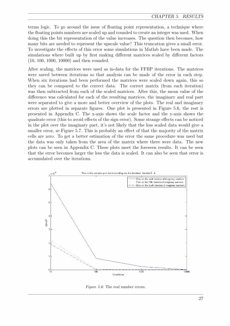
terms logic. To go around the issue of floating point representation, a technique wherethe floating points numbers are scaled up and rounded to create an integer was used. Whendoing this the bit representation of the value increases. The question then becomes, howmany bits are needed to represent the upscale value? This truncation gives a small error.To investigate the effects of this error some simulations in Matlab have been made. Thesimulations where built up by first making different matrices scaled by different factors(10, 100, 1000, 10000) and then rounded.
After scaling, the matrices were used as in-data for the FFBP iterations. The matriceswere saved between iterations so that analysis can be made of the error in each step.When six iterations had been performed the matrices were scaled down again, this sothey can be compared to the correct data. The correct matrix (from each iteration)was then subtracted from each of the scaled matrices. After this, the mean value of thedifference was calculated for each of the resulting matrices, the imaginary and real partwere separated to give a more and better overview of the plots. The real and imaginaryerrors are plotted in separate figures. One plot is presented in Figure 5.6, the rest ispresented in Appendix C. The x-axis shows the scale factor and the y-axis shows thequadrate error (this to avoid effects of the sign error). Some strange effects can be noticedin the plot over the imaginary part, it’s not likely that the less scaled data would give asmaller error, se Figure 5.7. This is probably an effect of that the majority of the matrixcells are zero. To get a better estimation of the error the same procedure was used butthe data was only taken from the area of the matrix where there were data. The newplots can be seen in Appendix C. These plots meet the foreseen results. It can be seenthat the error becomes larger the less the data is scaled. It can also be seen that error isaccumulated over the iterations.
Figure 5.6: The real number errors.
27

FAST FACTORIZED BACK-PROJECTION IN AN FPGA
Figure 5.7: Imaginary part error (with strage effects)
The values created in the radar data simulator have range between zero and five, theinteger part can be represented by three bits. Due to the lack of knowledge of the radarsystem, it is assumed that the values can be larger by adding one more bit, this makesthe representation four bits. This allows values between zero and fifteen. The Matlabsimulations show that by scaling the values with around 1000 times, the error becomesalmost zero. To achieve a scaling of about 1000 times the value is needed to be shiftedten bits, making the representation 14 bits. To be on the safe side, 16 bit representationshould be used.
5.3 Time to calculate the FFBP
For each iteration a different amount of calculations are needed. To obtain an estimationof the efficiency (in time) to calculate an iteration, a theoretical calculation of how manycycles it would take to calculate the 729 ∗ 2048 matrix image, (without optimization) wasperformed. The operation types required to calculate an FFBP iteration are:
• Read from memory.
• Write to memory.
• Addition
An addition in the PowerPC takes one clock cycle, a read takes (in the worst case) threeclock cycles and a write takes (in worst case) two clock cycles.
28

CHAPTER 5. RESULTS
The number of clock cycles needed to calculate an iteration can be divided into twoparts, one fixed (same for all iterations) and one varying part (iteration dependent). Thefixed part consists of six memory fetches for radar data, four additions and a write tothe memory. These operations are carried out for every cell/pixel in the matrix. The sixradar data values are the real and complex parts of the previous iterations. Four additionsare needed to add up the real and complex values. The other part, the varying part, isdependent of the size of the index matrices corresponding to the current iteration. Threeangle and two distance values are needed for the calculations; these values are saved inmatrices of the size stated in equation 3.3.
The three angles are the angles corresponding to the row in the sub-aperture from whichto take the radar data. The two distances corresponds to the columns where the data isstored. The reason why only two distances are needed is that the middle aperture is thedistance known due to that it corresponds to the current x-values of the cell/pixel that iscurrently calculated.
To find out the time needed for the calculations for an iteration the cycle number for thefixed part is added to the varying part. This is the total number of cycles needed for aspecific iteration. Since the system is running on a clock frequency of 100 MHz, the timewill be the number of cycles divided by the clock frequency. The calculations can be seenin table 5.1 and Appendix D.
Tabel: 5.1: Shows the difference in time between the iterations.
As the table shows, it takes about 2.33 seconds to calculate six iterations on a 729*2048matrix. The matrix is built on a PRF that gives the a spacing of 0.8 m, this gives flightdistance of 583 m. Now by rounding up the time to calculate the iterations to threeseconds to obtain more time for overhead the maximum speed allowed will in the end bearound 194 m/s. The airplane used in the CARABAS system is a Rockwell Sabreliner40A, this aircraft has a cruise speed of around 236 m/s without the antennas, but wethink the speed should be reduced when the antennas are mounted on the airplane [16].If the constraints are meet the proposed system should be able to calculate the iterationsin real-time.
29

FAST FACTORIZED BACK-PROJECTION IN AN FPGA
30

CHAPTER 6. CONCLUSION AND DISCUSSION
6 Conclusion and discussion
The goal(s) of this thesis were to a large extent achieved. The FFBP-algorithm has beenwritten in Matlab and simulated to give an estimation of how efficient it would be if animplementation based on tables were to be done. The hardware has been tested withsome different programs that would be contained in a system, but the calculations usingthe tables have not tested on the FPGA.
6.1 Engineering complexity
If an engineer would like to make a table based solution in their project, it could be fairlyeasy by the help of the Matlab files created in this project. The engineers within the fieldof knowledge are presumed to have at least a basic understanding of Matlab and a basicunderstanding of the FFBP. If this is true, it wouldn’t be hard for them to change orimprove the algorithm that was done in this project to obtain a faster and more accurateresults.
When building SoC systems, a modular way of thinking is always present. When a systemis based on modules, the maintenance and updating of the modules will be easy. In thisproject it was assumed that the first implementation was to be done in C, this howeverleads to a less modular system, but if the interpolation block and the complex calculationof the FFBP where to be done in HDL, the system would be more modular.
6.2 Scalability
The problem at hand, in the way it is done in this project, can be divided up betweenseveral FPGAs. This is done by dividing the table from Matlab into smaller parts anddistributing them and the radar-data associated, onto the different FPGSs, however thereis a limit to this depending on the iterations this because the data dependencies grow forevery iteration and more distance memory cells need to be accessed.
If more advanced interpolation methods were to be used, more communication betweenthe FPGAs would be needed, this can lead to a bottleneck in the system. However thisproblem could be minimized by having overlapping patches of data stored in the memory.In the later iterations the scalability will always be a problem. This because more distantmemory cell have to be accessed, this will give a lot of cache misses. To ease this someresearch of memory partitioning needs to be done
Scalability regarding to chip size can have a role in the performance. If the chip hasenough on chip Block-RAM, it might not need to access the external memory as much.This would probably give a performance increase; this would increase the probability ofcalculating the FFBP in real-time with the help of tables.
31

FAST FACTORIZED BACK-PROJECTION IN AN FPGA
6.3 Performance
This project is one of many parts in the digital signal processing chain. We do not havethe significant knowledge of the whole radar system to have an understanding of theenergy consumption of the other parts of the system, but this is an issue to be furtherinvestigated.
If the performance of this table based system is correctly calculated, the performancewould probably be enough to calculate the FFBP in real-time. This can be seen inAppendix D.
6.4 Portability
There are both benefits and drawbacks when using FPGAs in a system. Systems based onFPGAs are often (but not always) platform bound. This can make it difficult to exchangeone FPGA for another. But if the system is module based and the modules are kept asindependent as possible, it will make the porting less difficult. It is almost always easierto port a C-code than HDL-code to a new system or platform.
6.5 Discussion
This project studied the cooperation between FPGA, SoC and FFBP.
The learning process to understand the FFBP can be long, because the FFBP is a complexalgorithm without a large amount of written documentation. So take your time to learnit.
The theoretical computational speed achieved (presented in chapter 5.3 and AppendixD) by using a table based solution are favorable results. This however comes with adrawback. It’s very memory consuming. The tables grow fast with every iteration. Thefirst iteration use 2 ∗ 5∗ (number of range bins) integers, while the last (in our test casesixth) iteration uses ((number of aperture positions)/2) ∗ 5 ∗ (number of range bins)integers. This is a waste of resources but a fast solution.
No tests of advanced interpolation methods and index generating have been done, butwe think that this would lead to a drastic increase in computations needed to solve theproblem at hand, but by using dedicated logic on the FPGA the calculations might beable to be done in real-time.
A big challenge with this project is the large amount of data needed to be downloadedinto the DDR-memory. The lack of possibilities for downloading data directly into thememory gives rise to problems that did not connect to the actual project. Thus existingchannels of communicating had to be used in cooperation with C-programs to load thememory through the serial port. The serial communication programs tested did notsupport downloading enough values at one time to be of use and the time was coming toan end, so the time to write a program of our own for downloading the values was notenough.
The end result of this thesis is:
32

CHAPTER 6. CONCLUSION AND DISCUSSION
With the calculations we have done it can be shown that it is possible to calculate theFFBP in real-time using index tables. This solution is not the optimal solution for thisproblem because of the number of constraints. If the radar data matrix increases, all theother index matrices will grow even faster.
6.6 Future Work
This project is a starting point for a large area where all points are impossible to grasp inone project. The next step in this project could be to examine the index tables, this todetermine if there is a pattern to the values or not. If there is a pattern to the values inthe index matrices, it may be possible reduce the amount of values and use interpolationwithin the table to derive the missing values. This to save memory, but it will probablyincrease the computational burden for the CPU/HDL block.
Another continuation of the project could be to construct the index generator block inHDL-code. By doing this fewer calculations are needed to be done by the uni-processorand instead of calculating one coordinate at a time, all three could possibly be calculatedat once.
The most computationally burdened part of the system is the interpolation block. Con-struction and comparisons between different interpolations and how well they can beimplemented in an HDL-code is probably a whole project of its own.
In this thesis, two kinds of system proposals have been made. An interesting study wouldbe to implement and compare these two proposals.
Another interesting thought would to investigate other architectures than SoC on FPGAs.Investigating if for example Single Instruction Multiple Data (SIMD) architectures couldbe suitable to solve this kind of problem. Architectures that could be interesting are forexample the CSX600 from Clearspeed or the Cell processor from IBM, Sony and Toshiba[17] [18].
Energy consumption is important in all steps of the digital signal processing chain, evenmore important in small aircraft systems. So a study of the energy consumption of theFFBP when implemented on different kind of platforms and architectures would probablybe very interesting.
33

FAST FACTORIZED BACK-PROJECTION IN AN FPGA
34

BIBLIOGRAPHY
Bibliography
[1] D. Svensson and J. Johansson, “Suppression of Radio Frequency Interference in LowFrequency SAR,” Master’s thesis, Chalmers University of Technology Department ofSignals and Systems, 2004.
[2] A. Olofsson, “Signalbehandling i flygburen ultrabredbandig lagfrekvens-SAR,” Mas-ter’s thesis, Chalmers tekniska hogskolan Institutionen for radio- och rymdvetenskap,2003.
[3] A. Redding and B. Smith, “Modular FPGA architectures create truealternative to DSPs,” 2005-12-02. [Online]. Available: http://www.dsp-fpga.com/articles/redding and smith
[4] R. Williams, “Using FPGAs for DSP Image Processing,” 2005-12-04. [Online].Available: http://www.fpgajournal.com/articles/imaging hunt.htm
[5] B. Tithecott, “Why FPGAs are quickly moving into embedded signal processingsystems,” 2005-12-04. [Online]. Available: www.dsp-fpga.com/pdfs/SBS.Sum04.pdf
[6] W. S. George, Introduction to Airborne Radar second edition. Scitech publishing.incUSA, 1998, iSBN:1891121014.
[7] L. Ulander, P. Frolind, A. Gustavsson, H. Hellsten, T. Jonsson, B. Lairsson, andG. Stenstrom, “Analysis of CARABAS VHF SAR data from BALTASAR-96,” inRemote Sensing - A Scientific Vision for Sustainable Development, vol. 2, 1997, pp.797–799.
[8] M. Soumekh, Synthetic Aperture Radar Signal Processing. John Wiley & Sons inc.USA, 1999, iSBN:0-471-29706-2.
[9] L. M. H. Ulander, H. Hellsten, and G. Stenstrom,“Synthetic-Aperture Radar Process-ing Using Fast Factorized Back-Projection,” IEEE Transaction on aerospace andelectronic systems, vol. 39, no. 3, Jul 2003.
[10] M. Herberthson, L. Mylen, and A. Nelander, “Ekovision harblivit verklighet,” Framsyn, no. 2, 2002. [Online]. Available:http://www.foi.se/FOI/templates/Page 4157.aspx
[11] J. E. Fransson, F. Walter, K. Blennow, A. Gustavsson, and L. M. H. Ulander, “De-tection of Storm-Damaged Forested Areas Using Airborne CARABAS-II VHF SARImage Data,” IEEE Transactions on Geoscience and Remote Sensing, vol. 40, no. 10,Oct 2002.
[12] M. Magnusson and J. E. Fransson,“Combining CARABAS-II VHF SAR and LandsatTM Satellite Data for Estimation of Forest Stem Volume,” in Geoscience and RemoteSensing Symposium, 2004. IGARSS ’04. Proceedings. 2004 IEEE Internationa, vol. 4,2004, pp. 2327–2331.
35

FAST FACTORIZED BACK-PROJECTION IN AN FPGA
[13] B. Hallberg, G. Smith-Jonforsen, and L. M. H. Ulander, “Measurements on IndividualTrees Using Multiple VHF SAR Images,” IEEE Transactions on Geoscience andRemote Sensing, vol. 43, no. 10, pp. 2261–2269, Oct 2005.
[14] D. Marx, M. Nelson, E. Chang, W. Gillespie, A. Putney, and K. Warman, “Anintroduction to synthetic aperture sonar,” in Statistical Signal and Array Processing,2000. Proceedings of the Tenth IEEE Workshop on 14-16 Aug, 2000, pp. 717–721.
[15] “Virtex-4 FX LC Development Kit,” 2005-12-04. [Online]. Available:www.memec.com/uploaded/V4 FX LC Dev kit low1.pdf
[16] 2005-12-19. [Online]. Available: http://www.sabreliner.com/specifications.html
[17] Clearspeed, “CSX Processor Architecture Whitepaper,” 2005-12-14. [Online].Available: http://www.clearspeed.com/downloads/Architecture%20Whitepaper.pdf
[18] J. A. Kahle, M. N. Day, H. P. Hofstee, C. R. Johns, T. R. Maeurer, andD. Shippy, “Introduction to the Cell multiprocessor,” 2005-12-14. [Online]. Available:http://researchweb.watson.ibm.com/journal/rd/494/kahle.html
36

APPENDIX A. APPENDIX
A Appendix
In this appendix Matlab code for an example of one iteration can be seen. There is not abig difference in the code between iterations. The difference lies mainly in the length ofthe loops and the width of the test of the angles.
%-----------------------------------------------------------------%
%- FFBP Simulation Iteration Sixth -%
%- BY: Andreas Hast and Lars Johansson, Dec - 05 -%
%-----------------------------------------------------------------%
range = 0.8; % Range between apertures
[aperturenumber,rangebins]=size(pecho); % Find out the size of the
% radar matrix
% figure
% imagesc(abs(pecho))
%-------------------------------------------%
%- Calculations for the Sixth iteration. -%
%-------------------------------------------%
Sixth = zeros(aperturenumber,rangebins); %Create the resulting matrix
alfa1 = 0; %Create the variables for
alfa2 = 0; %the angles one for each
alfa3 = 0; %old sub-aperture
Tabell_Sixth = zeros(aperturenumber,rangebins,2);
%create a matrix where
%ranges are saved
Tabell_angle_Sixth = zeros(aperturenumber,rangebins,3);
%create a matrix where
%angles are saved
for i = 1:aperturenumber
for j = 1:rangebins
step = (90/729); %creates a variable that
%represent the size of each
%angle
indexering = 0; %resets a index variable
%that indexes the sub
%aperture
invstep = (180 - step); %creates a variable that
%represent the inverse of
37

FAST FACTORIZED BACK-PROJECTION IN AN FPGA
%step
for f = 1:728
if mod(i,729) == f
%Calculations of lengths and angles using the Law of sinus
%and the law of cosinus
b2 = j;
b1 = sqrt(((b2^2)+((243*range)^2)-(2*b2*243*range*cosd(step))));
b3 = sqrt(((b2^2)+((243*range)^2)-(2*b2*243*range*cosd(invstep))));
alfa1 = asind(b1*sind(step)/b2);
alfa2 = step;
alfa3 = asind(b3*sind(invstep)/b2);
%Decide from which row in the sub-aperture to collect value
%for summation one for each old sub-aperture
if b1 <= rangebins
e = 45;
for d = indexering:1:indexering+242
e = (e + 10/27);
%checks if the alfa1 is
%within the sub-aperture
if ((alfa1 < e) & (alfa1 > e - 10/27))
Tabell_Sixth(f,j,1) = round(b1);
Tabell_angle_Sixth(i,j,1) = d;
Sixth(i,j) = Sixth(i,j)+Fifth(i+d,ceil(b1));
end
end
end % End if b1 <= rangebins
e = 45;
for d = indexering+243:1:indexering+485
e = (e + 10/27);
%checks if the alfa2 is
%within the sub-aperture
if ((alfa2 < e) & (alfa2 > e - 10/27))
Tabell_angle_Sixth(i,j,2) = d;
Sixth(i,j) = Sixth(i,j)+Fifth(i+d,ceil(b2));
end
end
38

APPENDIX A. APPENDIX
if b3 <= rangebins
e = 45;
for d = indexering+486:1:indexering+728
e = e + 10/27;
%checks if the alfa3 is
%within the sub-aperture
if ((alfa3 < e) & (alfa3 > e - 10/27))
Tabell_Sixth(f,j,2) = round(b3);
Tabell_angle_Sixth(i,j,3) = d;
Sixth(i,j) = Sixth(i,j)+Fifth(i+d,ceil(b3));
end
end
end % End if b3 <= rangebins
end % End if mod(i,9) == f
step = (step + 20/81);
invstep = (invstep - 20/81);
indexering = (indexering-1);
end % End for f = 1:27
% Special case for the last row of the new subaperture when modulo is zero
if mod(i,729) == 0 % i=0
%Calculations of lengths and angles using the Law of sinus
%and the law of cosinus
b2 = j;
b1 = sqrt(((b2^2)+((243*range)^2)-(2*b2*243*range*cosd(step))));
b3 = sqrt(((b2^2)+((243*range)^2)-(2*b2*243*range*cosd(invstep))));
alfa1 = asind(b1*sind(step)/b2);
alfa2 = step;
alfa3 = asind(b3*sind(invstep)/b2);
%Decide from which row in the sub-aperture to collect value for
%summation one for each old sub-aperture
if b1 <= rangebins
e = 45;
for d = -728:1:-486
e = e + 10/27;
39

FAST FACTORIZED BACK-PROJECTION IN AN FPGA
%checks if the alfa1 is
%within the sub-aperture
if ((alfa1 < e) & (alfa1 > e - 10/27))
Tabell_Sixth(729,j,1) = round(b1);
Tabell_angle_Sixth(729,j,1) = d;
Sixth(i,j) = Sixth(i,j)+Fifth((i+d),ceil(b1));
end
end
end % End if b1 <= rangebins
e = 45;
for d = -485:1:-243
e = (e + 10/27);
%checks if the alfa2 is
%within the sub-aperture
if ((alfa2 < e) & (alfa2 > e - 10/27))
Tabell_angle_Sixth(729,j,2) = d;
Sixth(i,j) = Sixth(i,j)+Fifth((i+d),ceil(b2));
end
end
if b3 <= rangebins
e = 45;
for d = -242:1:0
e = (e + 10/27);
%checks if the alfa3 is
%within the sub-aperture
if ((alfa3 < e) & (alfa3 > e - 10/27))
Tabell_Sixth(729,j,2) = round(b3);
Tabell_angle_Sixth(729,j,3) = d;
Sixth(i,j) = Sixth(i,j)+Fifth((i+d),ceil(b3));
end
end
end % End if b3 <= rangebins
end % End if mod(i,27) == 0
end % End for j = 1:rangebins
end % End for i = 1:aperturenumber
% figure
% imagesc(abs(Sixth))
40

APPENDIX B. APPENDIX
B Appendix
The figures shown below show the data focusing after each iteration, starting with theoriginal radar data. The data is based on a pulse spacing of 0.8 m and an aperture angleof 90 degrees.
Figure: A.1: Raw radar data
41

FAST FACTORIZED BACK-PROJECTION IN AN FPGA
Figure: A.2: First iteration
Figure: A.3: Second iteration
42

APPENDIX B. APPENDIX
Figure: A.4: Third iteration
Figure: A.5: Fourth Iteration
43

FAST FACTORIZED BACK-PROJECTION IN AN FPGA
Figure: A.6: Fifth iteration
Figure: A.7: Sixth iteration
44

APPENDIX C. APPENDIX
C Appendix
The figures shown below show the rounding errors when scaling the floating point numbers.
Figure: B.1: First half of the real number errors.
45

FAST FACTORIZED BACK-PROJECTION IN AN FPGA
Figure: B.2: Second half of the real number errors.
46

APPENDIX C. APPENDIX
Figure: B.3: First half of the complex number errors.
47

FAST FACTORIZED BACK-PROJECTION IN AN FPGA
Figure: B.4: Second half of the complex number errors.
48

APPENDIX C. APPENDIX
Figure: B.5: First half of the real number error of selected data
49

FAST FACTORIZED BACK-PROJECTION IN AN FPGA
Figure: B.6: Second half of the real number error of selected data
50

APPENDIX C. APPENDIX
Figure: B.7: First half of the complex number error of selected data
51

FAST FACTORIZED BACK-PROJECTION IN AN FPGA
Figure: B.8: Second half of the complex number error of selected data
52

APPENDIX D. APPENDIX
D Appendix
In this appendix one can see the theoretically calculated numbers of clock cycles neededto calculate a 729*2048 matrix and the time it takes for the platform to calculate them.By calculating the time it takse to calculate the values needed the maximum speed of theaircraft can be calculated. This can be seen below.
53