Fast Development with DaVinci On Screen Display (OSD)
12
Application Report SPRAAD7 – July 2006 Fast Development with DaVinci On Screen Display (OSD) Juan Gonzales ................................................................................. Digital Customer Applications Team ABSTRACT While On Screen Display (OSD) functionality became prevalent as a cheaper alternative to using buttons/knobs to control television settings, in today’s society, it seems like everyday a new gadget comes out which uses OSDs. Imagine a video phone or set-top application for a minute; both of these applications require video overlaid with some graphics OSD, and may require some blending between video and a graphic (or OSD) plane. In order to come up with what the final screen will look like, engineers often go through several iterations of resizing video windows and rearranging graphic blocks. Each of these iterations comes at the cost of two precious resources: time and money. Now imagine you can draw your graphics in almost any open source or commercially available graphics program and quickly drop your new graphics (or OSD) into the screen to test how it would look before writing a single line of code, allowing you to quickly change your graphics and test how it looks quickly until you have it just right. You do not have to imagine anymore, DaVinci makes this a reality. This application report will show how easy and fast it can be to test/implement your OSD ideas on Texas Instrument’s DaVinci™ platform using a standard open source graphics editor (i.e. GIMP), and the power of the Linux operating system. This application report contains a tar file that can be downloaded from this link. http://www-s.ti.com/sc/psheets/spraad7/spraad7.zip Topic .................................................................................................. Page Trademarks ................................................................................ 2 1 Background ............................................................................... 2 2 Putting it All Together ................................................................. 4 3 Conclusion ................................................................................ 4 Appendix A OSD Demo ....................................................................... 5 Appendix B BMP to RGB565 Conversion Code .................................... 10 SPRAAD7 – July 2006 Fast Development with DaVinci On Screen Display (OSD) 1 Submit Documentation Feedback
-
Upload
truongdang -
Category
Documents
-
view
215 -
download
0
Transcript of Fast Development with DaVinci On Screen Display (OSD)

Application ReportSPRAAD7–July 2006
Fast Development with DaVinci On Screen Display (OSD)Juan Gonzales ................................................................................. Digital Customer Applications Team
ABSTRACT
While On Screen Display (OSD) functionality became prevalent as a cheaperalternative to using buttons/knobs to control television settings, in today’s society, itseems like everyday a new gadget comes out which uses OSDs.
Imagine a video phone or set-top application for a minute; both of these applicationsrequire video overlaid with some graphics OSD, and may require some blendingbetween video and a graphic (or OSD) plane. In order to come up with what the finalscreen will look like, engineers often go through several iterations of resizing videowindows and rearranging graphic blocks. Each of these iterations comes at the cost oftwo precious resources: time and money. Now imagine you can draw your graphics inalmost any open source or commercially available graphics program and quickly dropyour new graphics (or OSD) into the screen to test how it would look before writing asingle line of code, allowing you to quickly change your graphics and test how it looksquickly until you have it just right. You do not have to imagine anymore, DaVinci makesthis a reality.
This application report will show how easy and fast it can be to test/implement yourOSD ideas on Texas Instrument’s DaVinci™ platform using a standard open sourcegraphics editor (i.e. GIMP), and the power of the Linux operating system.
This application report contains a tar file that can be downloaded from this link.http://www-s.ti.com/sc/psheets/spraad7/spraad7.zip
Topic .................................................................................................. Page
Trademarks................................................................................ 21 Background ............................................................................... 22 Putting it All Together ................................................................. 43 Conclusion ................................................................................ 4Appendix A OSD Demo ....................................................................... 5Appendix B BMP to RGB565 Conversion Code .................................... 10
SPRAAD7–July 2006 Fast Development with DaVinci On Screen Display (OSD) 1Submit Documentation Feedback

www.ti.com
Trademarks
1 Background
1.1 About DaVinci OSD
Video Port B ack End Featu res
Video Window 0
v id eo
Video Win dow 1
v id eo
OSD Window 0
(b i tm ap)
OSD Win dow 1
(b itm ap )
Curso r
/d ev /fb /1 YCb Cr 4:2:2
/d ev /fb /3 YCb Cr 4:2:2
/d ev /fb /0 RGB16
/dev/fb /2 att r ibu te
u Tw o v ideo w indow s fo r p ic tu re-in -p ic tu re
u Tw o OSD w in dow s o r one OSD w indow + attr ibu te w in dow
u /dev/fb2 at t r ibu te m o de prov id es p ixel-level alph a b len d ing
Background
DaVinci is a trademark of Texas Instruments.
This section provides necessary background for understanding how the DaVinci platform makes OSDdevelopment so easy and fast.
It is important to understand that Texas Instrument’s DaVinci platform consists of more than just a familyof processors, such as TMS320DM6443 and TMS320DM6446; it also includes world-class developmenttools, software and support. A combination of these components makes DaVinci a faster developmentplatform for efficient and compelling video (and audio) applications.
This section focuses on the OSD capabilities of the TMS320DM6443 and TMS320DM6446 processors asthese are the DaVinci family processors that are currently available. These processors support abackground window color, two video windows, two OSD windows, and a cursor window, in order ofascending priority as shown in Figure 1.
Figure 1. TMS320DM6443/TMS320DM6446 OSD Hierarchy
One unique aspect of the second OSD window (OSDWIN1) is that it can be configured as an attributewindow to control the blending (i.e., transparency) between the video windows and the first OSD window(OSDWIN0). Since this “alpha” blending function is the most common use of OSDWIN1, this applicationreport focuses on the configuration where the first OSD window (OSDWIN0) is used to display OSDgraphics, and the second OSD window (OSDWIN1) is used as an attribute window to control blending.
The OSD windows are configured to accept either RGB565 or bitmap data. Often, RGB, bitmap, and rawdata formats are used interchangeably in the technology industry. These formats are essentially the sameif they use the same number of bits per pixel. In DaVinci processors, this is not the case, and thus theyprovide the option to configure OSD for either RGB565 or bitmap. When the OSD window is configured toreceive bitmap data, it uses a color lookup table (CLUT) with a total of 256 entries. This means themaximum color depth of a bitmap pixel is 8-bits (4-bit, 2-bit, and 1-bit color depths are also supported).When the OSD window is configured to receive RGB565 data, CLUT is not required as RGB data fromexternal memory is converted to YCbCr in hardware prior to reaching OSD; RGB565 uses 16-bit per pixeland therefore, can represent 64K colors. Both windows can be configured to accept bitmap datasimultaneously; however, only one OSD window can be configured to accept RGB565 data at a time.Therefore, if the second OSD window is used as an attribute window as suggested above, it is preferableto use RGB565 mode on the first OSD window, primarily because it has access to 16-bits (64K colors).
Fast Development with DaVinci On Screen Display (OSD)2 SPRAAD7–July 2006Submit Documentation Feedback

www.ti.com
1.2 About Linux, Drivers and Video
1.3 About Graphics Editors
Background
Linux has two predominant driver architectures, block drivers and character drivers. Block drivers allow outof order access and can be mounted into the file-system. These include drivers for hard disk drives,external RAM, and compact flash devices just to name a few. Character drivers are read as streams in aFIFO order ( e.g. drivers for sound and video). As one can probably guess, OSD functionality is providedby character (video display) drivers.
Another feature of Linux is that character devices can be used in a similar manner to accessing files. Thismeans you can open, read, write, and close these devices just like files. From the Linux command prompt,you can copy (cp), display (cat), and pipe (>>) data to/from another file. This powerful feature allows datato be placed into the OSD window without writing a single line of code.
The DaVinci platform provides access to the video hardware primarily using two Linux drivers, the V4L2capture driver, and the FBDev display driver.
• Video For Linux 2 (V4L2) is a standard, second generation Linux video input driver, which fixed anumber of design bugs of the first version.
• FBDev is a standard Linux video output driver used to map the frame buffer of a display device, suchas DaVinci processors, into user space.
The focus of this application report is on the Linux frame buffer display device (i.e., FBDev driver) becauseit contains the OSD features. The frame buffer device provides an abstraction for the display hardware. Itrepresents the video output hardware (DaVinci OSD in this case) as a frame buffer device, thus allowingapplication software to access graphics hardware by “just writing to a buffer”. As mentioned above, theoutput device buffer is accessed via a special file-like node, usually located in the /dev directory. In thiscase, the path you are interested in for changing the DaVinci OSD is /dev/fb/0. Using this path, youcan modify the display through a well defined interface which includes file-like operations (i.e.,open, read,write, close) and device specific commands (ioctls to query/set information about the hardware).
For those new to Linux, they should familiarize themselves with the following copy command below:cp - copy (e.g. >cp osd.r16 /dev/fb/0 -- copies osd.r16 file to /dev/fb/0 device)
All popular graphic/image editors in the market today use the file extension to determine the proper codecrequired to decode a file for viewing or editing. There are many widely accepted industry file extensionssuch a jpg, jpeg, bmp, gif, tiff, and png, which represent their corresponding image formats. All theseimage formats require some header information to describe the image attributes required by that particularformat. The image attributes include items such as height, width, and bits per pixel (bpp). Using the fileextension, the graphics utilities can correctly parse the header file as well as the image contents.
As you have learned, TMS320DM6443/TMS320DM6446 processors support two formats of input into theirOSD frame buffers with RGB being the most appealing since it provides a greater number of colors. SinceRGB data represents raw uncompressed data, there is no additional header information for an imageeditor to decode. Unfortunately though, there are many flavors of RGB formats, such as RGB24 (8:8:8),RGB16 (5:6:5), and RGB15 (5:5:5). Without some type of header information to tell the image editor theproper format of the data, the editor can only guess. For this reason, most editors do not support RGBfiles, and the few that do, use “.rgb” file extension to represent only the most common RGB type, (e.g.RGB24). Since the DM6443/6 OSD frame buffer uses RGB16 (5:6:5), there is a disconnect between thehardware and the available graphic editors.
Fortunately, the uncompressed BMP file format available in most editors is essentially some headerinformation followed by bitmap data. Furthermore, bitmap data format and RGB data format are essentiallythe same so long as you have the same number of bits per pixel. Therefore, it is chosen as the preferredfile format for the fast OSD development procedure listed in the next section. To convert from 24-bit BMP(most common) to RGB16 (5:6:5) format -- which is expected by the OSD frame buffer -- a small Cprogram was written and is included in the .tar.gz file accompanying this application note and is also listedin Appendix B.
SPRAAD7–July 2006 Fast Development with DaVinci On Screen Display (OSD) 3Submit Documentation Feedback

www.ti.com
2 Putting it All Together
3 Conclusion
Putting it All Together
So now that you are armed with this knowledge, how do you go about placing graphics into theTMS320DM6443/TMS320DM6446 OSD window without writing a single line of code? As you learned inSection 1.2, by writing a single command at the Linux prompt (>cp osd.r16 /dev/fb/0), you can copy thecontents of osd.r16 file into OSD frame buffer, thus displaying it. Where does osd.r16 file come from? Thisfile contains the image you want to display as your OSD; therefore after designing your OSD in a graphicseditor such as GIMP, this file is generated by running the small conversion utility provided in theaccompanying tar.gz file. But what format should be used to save the file created in GIMP? As you havelearned, in Section 1.3, the preferred format used here is BMP.
To summarize the process:
1. Create/revise OSD design in your favorite graphics editor (e.g GIMP) and save in BMP format.2. Run the small program provided in the accompanying tar.gz file to convert to RGB565 format.>./bmpToRgb16 mysod.bmp (this will generate osd.r16 file)
3. Place the converted file into OSD frame buffer to view results> cp osd.r16 /dev/fb/0
4. Repeat steps 1 thru 3 until you are satisfied with the final design. Save the osd.r16 file to be loaded byapplication source code.
It should be mentioned that the attribute window should not be set to 100% video (all zeros), as thisblending level does not allow for OSD graphics to be displayed. For an example on how to run a demothat encompasses the ideas presented in this document on the DaVinci DVEVM, please refer toAppendix A.
It is relatively simple to design your OSD graphics on the DaVinci platform. Literally, draw OSD graphics inalmost any open source or commercially available graphics program. Quickly drop them onto the screento test how it looks before writing a single line of code, thus allowing you to quickly change and test until itis just right. This is just one example of how the DaVinci platform can help reduce your time to market anddevelopment costs.
4 Fast Development with DaVinci On Screen Display (OSD) SPRAAD7–July 2006Submit Documentation Feedback

www.ti.com
Appendix A OSD Demo
A.1 Setting up Demo
Appendix A
The demo described here executes on the TMDXEVM6446 digital video evaluation module(DVEVM) shown in Figure A-1. Although not required, this demo uses a VMware Red HatEnterprise Linux (RHEL) virtual machine image as the Host. To avoid additional configuration steps,this setup also connects DVEVM to REHL host using router, to take advantage of router’s DHCPserver capabilities. The following sections cover steps on setting up and running the demo.
Figure A-1. TMDXEVM6446, DVEVM
1. Set the dip switches in the red block in the center of the DVEVM to the following pattern: 1011111110(switch #2 and #10 off, all others on). See Figure A-1.
2. Use a serial terminal connection to the DVEVM in 115200 baud 8-–1 configuration. You may either useminicom within the VMware image by typing:host # minicomor terminal emulator such as hyperterminal or terra term in Windows.
3. Cycle power to the DVEVM board. Press any key at the beginning of the u-boot startup sequence(while it is counting down) to interrupt the boot sequence and enter u-boot command mode. If you donot enter the u-boot command after power-cycling the board, check the dipswitch settings listed in step1) as well as your serial terminal settings from step 2).
SPRAAD7–July 2006 Fast Development with DaVinci On Screen Display (OSD) 5Submit Documentation Feedback
www.ti.com
Setting up Demo
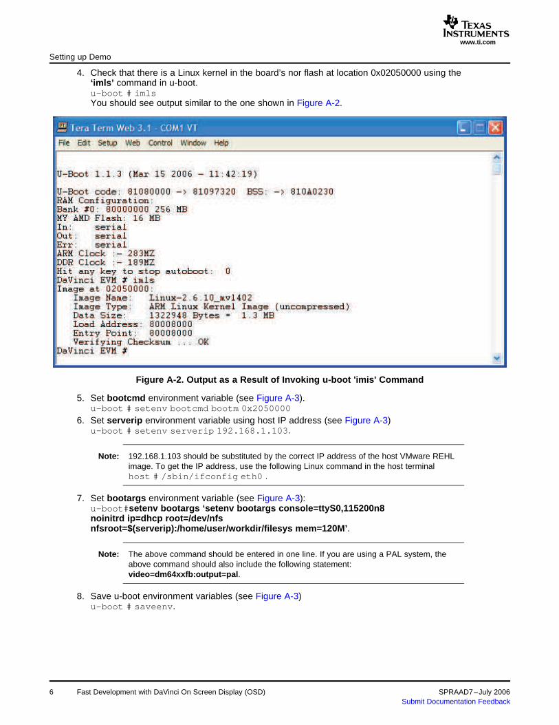
4. Check that there is a Linux kernel in the board’s nor flash at location 0x02050000 using the‘imls’ command in u-boot.u-boot # imlsYou should see output similar to the one shown in Figure A-2.
Figure A-2. Output as a Result of Invoking u-boot 'imis' Command
5. Set bootcmd environment variable (see Figure A-3).u-boot # setenv bootcmd bootm 0x2050000
6. Set serverip environment variable using host IP address (see Figure A-3)u-boot # setenv serverip 192.168.1.103.
Note: 192.168.1.103 should be substituted by the correct IP address of the host VMware REHLimage. To get the IP address, use the following Linux command in the host terminalhost # /sbin/ifconfig eth0 .
7. Set bootargs environment variable (see Figure A-3):u-boot#setenv bootargs ‘setenv bootargs console=ttyS0,115200n8noinitrd ip=dhcp root=/dev/nfsnfsroot=$(serverip):/home/user/workdir/filesys mem=120M’.
Note: The above command should be entered in one line. If you are using a PAL system, theabove command should also include the following statement:video=dm64xxfb:output=pal.
8. Save u-boot environment variables (see Figure A-3)u-boot # saveenv.
6 Fast Development with DaVinci On Screen Display (OSD) SPRAAD7–July 2006Submit Documentation Feedback

www.ti.com
Setting up Demo
Figure A-3. Setting the u-boot Environment Variables
9. Reboot DVEVM and Login as “root” (there is no password).10. On the host, place the accompanying tar.gz file under ‘/home/user/workdir/filesys/’. This is the
directory that will be NFS mounted per u-boot configuration (see Figure A-3) and thus visible toDVEVM.
11. Extract demo files by running ‘tar’ Linux commandhost #: tar -xzvf demo2.tar.gzThis will create a directory named ‘demo2’.
12. Change to ‘demo2’ directory.host # cd demo2The contents of this directory include
-bmpToRgb16 (executable binary of BMP to RGB conversion utility)
-bmpToPgb16.c (source code of conversion utility)
-MakeFile (Makefile for ease of rebuilding conversion utility)
-osd.r24 (GIMP generated graphics file passed in to utility)
-osd.r16 (file generated by conversion utility)
-allosd.attr (attribute blending data that allows only OSD visibility)
-allvid.attr (attribute blending data that allows only video visibility)
-halfhalf.attr (blending data that allows both video and OSD to be seen)
SPRAAD7–July 2006 Fast Development with DaVinci On Screen Display (OSD) 7Submit Documentation Feedback

www.ti.com
A.2 Running the Demo
Running the Demo
1. On the host terminal, change to the Demo 2 directoryhost # cd /home/user/seminar/demo2.
2. Launch gimp (a Linux paint tool) in the host computer.host # gimp.
3. Draw a picture within gimp.q Press ctrl-n or select file->new… to create a new picture.q Select a resolution of 720x480 if you are configured for NTSC output and 720x576 if you are
configured for PAL output. Keep the default type of RGB (as opposed to grayscale)q Press ctrl-s or clicking the > in the top left corner of the image and selecting file->save as…q From the “determine file type” pulldown selection, select BMP (bitmap).q Though not required, it will add clarity to save your image with the extension “.r24”.
Figure A-4. Drawing a Picture in GIMP
4. Convert your newly saved RGB 24 image to RGB 16 using bmpToRgb16 for instance, if you savedyour image as “osd.r24”host # ./bmpToRgb16 osd.r24 720 480 for an NTSC system, orhost # ./bmpToRgb16 osd.r24 720 576 for a PAL system.
Note: The output file will be saved as “osd.r16”.
5. Copy the osd.r16 file into the OSD node using the cp command:DVEVM # cp osd.r16 /dev/fb/0.
8 Fast Development with DaVinci On Screen Display (OSD) SPRAAD7–July 2006Submit Documentation Feedback
www.ti.com
Running the Demo
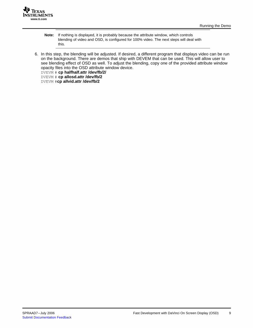
Note: If nothing is displayed, it is probably because the attribute window, which controlsblending of video and OSD, is configured for 100% video. The next steps will deal withthis.
6. In this step, the blending will be adjusted. If desired, a different program that displays video can be runon the background. There are demos that ship with DEVEM that can be used. This will allow user tosee blending effect of OSD as well. To adjust the blending, copy one of the provided attribute windowopacity files into the OSD attribute window device.DVEVM # cp halfhalf.attr /dev/fb/2/DVEVM # cp allosd.attr /dev/fb/2DVEVM #cp allvid.attr /dev/fb/2
SPRAAD7–July 2006 Fast Development with DaVinci On Screen Display (OSD) 9Submit Documentation Feedback
www.ti.com
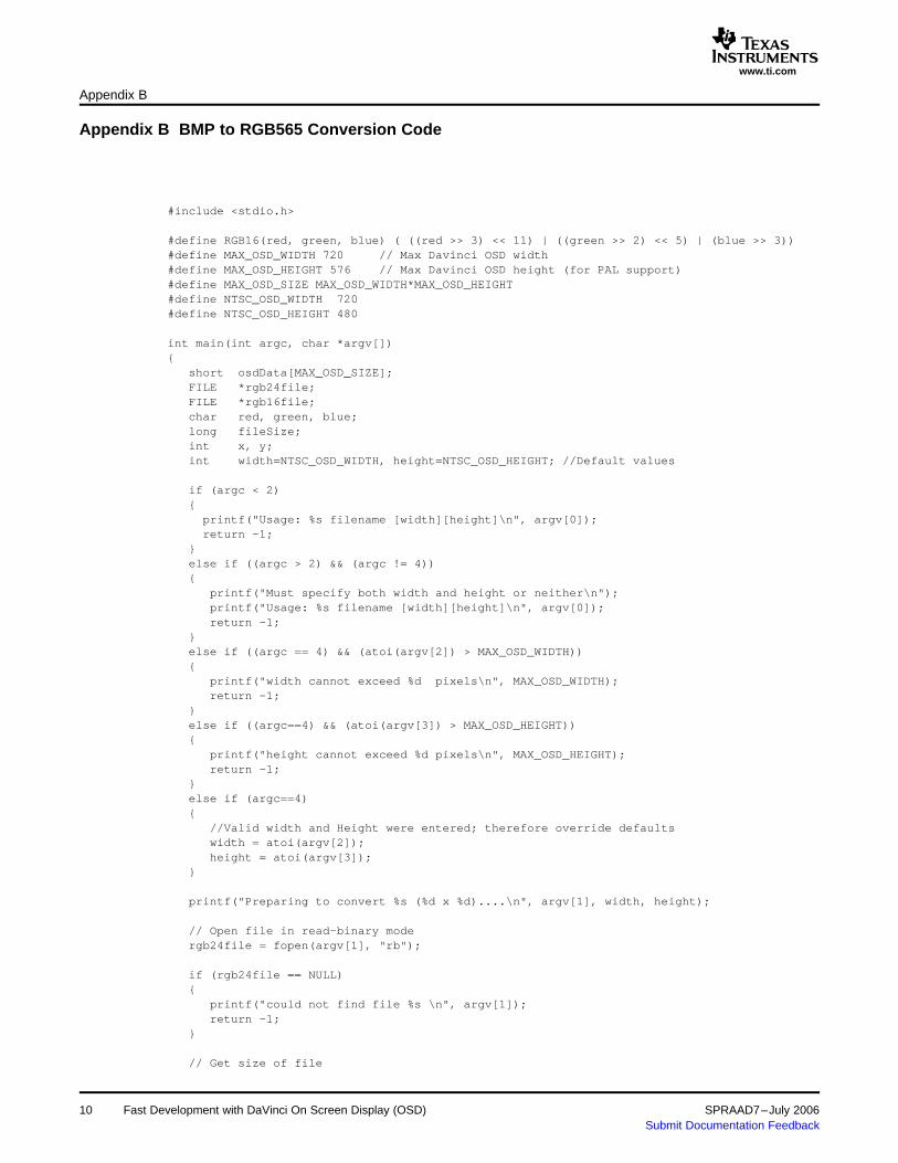
Appendix B BMP to RGB565 Conversion Code
Appendix B
#include <stdio.h>
#define RGB16(red, green, blue) ( ((red >> 3) << 11) | ((green >> 2) << 5) | (blue >> 3))#define MAX_OSD_WIDTH 720 // Max Davinci OSD width#define MAX_OSD_HEIGHT 576 // Max Davinci OSD height (for PAL support)#define MAX_OSD_SIZE MAX_OSD_WIDTH*MAX_OSD_HEIGHT#define NTSC_OSD_WIDTH 720#define NTSC_OSD_HEIGHT 480
int main(int argc, char *argv[]){
short osdData[MAX_OSD_SIZE];FILE *rgb24file;FILE *rgb16file;char red, green, blue;long fileSize;int x, y;int width=NTSC_OSD_WIDTH, height=NTSC_OSD_HEIGHT; //Default values
if (argc < 2){
printf("Usage: %s filename [width][height]\n", argv[0]);return -1;
}else if ((argc > 2) && (argc != 4)){
printf("Must specify both width and height or neither\n");printf("Usage: %s filename [width][height]\n", argv[0]);return -1;
}else if ((argc == 4) && (atoi(argv[2]) > MAX_OSD_WIDTH)){
printf("width cannot exceed %d pixels\n", MAX_OSD_WIDTH);return -1;
}else if ((argc==4) && (atoi(argv[3]) > MAX_OSD_HEIGHT)){
printf("height cannot exceed %d pixels\n", MAX_OSD_HEIGHT);return -1;
}else if (argc==4){
//Valid width and Height were entered; therefore override defaultswidth = atoi(argv[2]);height = atoi(argv[3]);
}
printf("Preparing to convert %s (%d x %d)....\n", argv[1], width, height);
// Open file in read-binary modergb24file = fopen(argv[1], "rb");
if (rgb24file == NULL){
printf("could not find file %s \n", argv[1]);return -1;
}
// Get size of file
10 Fast Development with DaVinci On Screen Display (OSD) SPRAAD7–July 2006Submit Documentation Feedback

www.ti.com
Appendix B
fseek(rgb24file, 0, SEEK_END);fileSize = ftell(rgb24file);fseek(rgb24file, 0, SEEK_SET);printf("size %d\n", fileSize);
//Skip BMP header informationfseek(rgb24file, 54, SEEK_SET);fileSize = fileSize - 54;
//Ensure file size does not exceed Max supported OSD sizeif (fileSize > (MAX_OSD_SIZE*3)){
printf("This file is too large, maximum supported size is 720x576x3\n");}else if (((fileSize % 3) !=0)|| (fileSize != (width*height*3))){
printf("this file does not have the size expected \n");}else{
for( x=0; x < (width*height); ++x){
fread(&blue, sizeof(char), 1, rgb24file);fread(&green, sizeof(char), 1, rgb24file);fread(&red, sizeof(char), 1, rgb24file);
osdData[x] = RGB16(red, green, blue);}
// Open file in read-binary modergb16file = fopen("osd.r16", "wb");for (y= height -1; y >=0; --y){
for (x=0; x < width; ++x){
fwrite(&osdData[(width*y) + x], sizeof(short), 1, rgb16file);}
}fclose(rgb16file);
}
fclose(rgb24file);return;
}
SPRAAD7–July 2006 Fast Development with DaVinci On Screen Display (OSD) 11Submit Documentation Feedback

IMPORTANT NOTICE
Texas Instruments Incorporated and its subsidiaries (TI) reserve the right to make corrections, modifications,enhancements, improvements, and other changes to its products and services at any time and to discontinueany product or service without notice. Customers should obtain the latest relevant information before placingorders and should verify that such information is current and complete. All products are sold subject to TI’s termsand conditions of sale supplied at the time of order acknowledgment.
TI warrants performance of its hardware products to the specifications applicable at the time of sale inaccordance with TI’s standard warranty. Testing and other quality control techniques are used to the extent TIdeems necessary to support this warranty. Except where mandated by government requirements, testing of allparameters of each product is not necessarily performed.
TI assumes no liability for applications assistance or customer product design. Customers are responsible fortheir products and applications using TI components. To minimize the risks associated with customer productsand applications, customers should provide adequate design and operating safeguards.
TI does not warrant or represent that any license, either express or implied, is granted under any TI patent right,copyright, mask work right, or other TI intellectual property right relating to any combination, machine, or processin which TI products or services are used. Information published by TI regarding third-party products or servicesdoes not constitute a license from TI to use such products or services or a warranty or endorsement thereof.Use of such information may require a license from a third party under the patents or other intellectual propertyof the third party, or a license from TI under the patents or other intellectual property of TI.
Reproduction of information in TI data books or data sheets is permissible only if reproduction is withoutalteration and is accompanied by all associated warranties, conditions, limitations, and notices. Reproductionof this information with alteration is an unfair and deceptive business practice. TI is not responsible or liable forsuch altered documentation.
Resale of TI products or services with statements different from or beyond the parameters stated by TI for thatproduct or service voids all express and any implied warranties for the associated TI product or service andis an unfair and deceptive business practice. TI is not responsible or liable for any such statements.
Following are URLs where you can obtain information on other Texas Instruments products and applicationsolutions:
Products Applications
Amplifiers amplifier.ti.com Audio www.ti.com/audio
Data Converters dataconverter.ti.com Automotive www.ti.com/automotive
DSP dsp.ti.com Broadband www.ti.com/broadband
Interface interface.ti.com Digital Control www.ti.com/digitalcontrol
Logic logic.ti.com Military www.ti.com/military
Power Mgmt power.ti.com Optical Networking www.ti.com/opticalnetwork
Microcontrollers microcontroller.ti.com Security www.ti.com/security
Low Power Wireless www.ti.com/lpw Telephony www.ti.com/telephony
Video & Imaging www.ti.com/video
Wireless www.ti.com/wireless
Mailing Address: Texas Instruments
Post Office Box 655303 Dallas, Texas 75265
Copyright 2006, Texas Instruments Incorporated