Fast Binary Image Processing Using Binary Decision … · Mots-cle´ : traitement d’images...
28
HAL Id: inria-00073695 https://hal.inria.fr/inria-00073695 Submitted on 24 May 2006 HAL is a multi-disciplinary open access archive for the deposit and dissemination of sci- entific research documents, whether they are pub- lished or not. The documents may come from teaching and research institutions in France or abroad, or from public or private research centers. L’archive ouverte pluridisciplinaire HAL, est destinée au dépôt et à la diffusion de documents scientifiques de niveau recherche, publiés ou non, émanant des établissements d’enseignement et de recherche français ou étrangers, des laboratoires publics ou privés. Fast Binary Image Processing Using Binary Decision Diagrams Luc Robert, Grégoire Malandain To cite this version: Luc Robert, Grégoire Malandain. Fast Binary Image Processing Using Binary Decision Diagrams. RR-3001, INRIA. 1996. <inria-00073695>
-
Upload
truongnguyet -
Category
Documents
-
view
215 -
download
0
Transcript of Fast Binary Image Processing Using Binary Decision … · Mots-cle´ : traitement d’images...

HAL Id: inria-00073695https://hal.inria.fr/inria-00073695
Submitted on 24 May 2006
HAL is a multi-disciplinary open accessarchive for the deposit and dissemination of sci-entific research documents, whether they are pub-lished or not. The documents may come fromteaching and research institutions in France orabroad, or from public or private research centers.
L’archive ouverte pluridisciplinaire HAL, estdestinée au dépôt et à la diffusion de documentsscientifiques de niveau recherche, publiés ou non,émanant des établissements d’enseignement et derecherche français ou étrangers, des laboratoirespublics ou privés.
Fast Binary Image Processing Using Binary DecisionDiagrams
Luc Robert, Grégoire Malandain
To cite this version:Luc Robert, Grégoire Malandain. Fast Binary Image Processing Using Binary Decision Diagrams.RR-3001, INRIA. 1996. <inria-00073695>

ISS
N 0
249-
6399
ap por t de r ech er ch e
INSTITUT NATIONAL DE RECHERCHE EN INFORMATIQUE ET EN AUTOMATIQUE
Fast Binary Image Processing Using BinaryDecision Diagrams
Luc Robert, Gregoire Malandain
N˚ 3001
Octobre 1996
THEME 3


Fast Binary Image Processing Using Binary DecisionDiagrams
Luc Robert* , Gregoire Malandain**
Theme 3 — Interaction homme-machine,images, donnees, connaissances
Projets Robotvis, Epidaure
Rapport de recherche n˚3001 — Octobre 1996 — 24 pages
Abstract: Many classical image processing tasks can be realized as evaluations of a booleanfunction over subsets of an image. For instance, the simplicity test used in 3D thinning re-quires examining the 26 neighbors of each voxel and computing a single boolean functionof these inputs. In this article, we show how Binary Decision Diagrams can be used to pro-duce automatically very efficient and compact code for such functions. The total number ofoperations performed by a generated function is at most one test and one branching for eachinput value (e.g., in the case of 3D thinning, 26 tests and branchings). At each stage, thefunction is guaranteed to examine only the pertinent input data, i.e., the values which affectthe result.
As an example, we consider the 2D and 3D simplicity tests in digital topology, and thin-ning processes. We produce functions much faster than our previously optimized implemen-tations [18, 4], and than any other implementation we know of. In the case of 3D simplicitytest, on average, at each voxel only 8.7 neighboring voxel values are examined.
Key-words: binary image processing, BDD, mathematical morphology, digital topology
(Resume : tsvp)
* Email : [email protected]** Email : [email protected]
Unite de recherche INRIA Sophia-Antipolis2004 route des Lucioles, BP 93, 06902 SOPHIA-ANTIPOLIS Cedex (France)
Telephone : (33) 93 65 77 77 – Telecopie : (33) 93 65 77 65

Traitement Rapide d’Images Binaires a l’aide deDiagrammes de Decision Binaires
Resume : Un certain nombre de techniques de traitement d’image reposent sur l’evaluationd’une fonction booleenne sur des parties de l’image. Par exemple, la caracterisation despoints simples utilisee pour l’amincissement 3D requiert d’examiner les 26 voisins de chaquevoxel, et de calculer une fonction booleenne de ces valeurs. Dans cet article, nous montronscomment utiliser les Diagrammes de Decision Binaires pour produire automatiquement ducode tres efficace et compact implementant de telles fonctions. Le nombre total d’operationseffectuees par la fonction produite est au plus d’un test et un branchement par valeur d’entree(c’est-a-dire, dans le cas de l’amincissement 3D, 26 test et branchements). A chaque etape,la fonction n’examine que les valeurs qui ont une influence sur le resultat.
Comme application, nous considerons la caracterisation des points simples en topologiediscrete 2D et 3D, et plusieurs techniques d’amincissement 3D. Nous produisons des fonc-tions beaucoup plus efficaces que nos implementations optimisees existantes [18, 4], et quetoutes les autres implementations que nous connaissons. Pour caracteriser les points simplesen 3D, il suffit en moyenne pour chaque voxel d’examiner 8.7 voisins.
Mots-cle : traitement d’images binaires, bdd, morphologie mathematique, topologie dis-crete
Fast Binary Image Processing Using Binary Decision Diagrams 3
1 Introduction
Many classical image processing techniques proceed by analyzing at each elementof the image (pixel, voxel) the values of its neighbors. Considering the particularcase of binary images, a number of techniques for image processing have been de-veloped in the domains of mathematical morphology [26, 27], digital topology [13],or for other specific tasks such as image edge linking [10, 22]. Each of these tech-niques relies on at least one function which, for a given pixel, analyzes the values ofits neighbors. This function has to be evaluated many times during the process. Infact, a large fraction of the computational effort is devoted to evaluating this func-tion, and the implementation of the function itself has a tremendous effect on theefficicency of the whole process. Several solutions have been proposed for efficientimplementations so far.
First, it is sometimes possible to decompose the original function into more ele-mentary functions, which can be evaluated very efficiently. For instance, in mathe-matical morphology, a 3x3x3 structuring element is separable and can be decompo-sed into the product of three structuring elements (3x1x1, 1x3x1 and 1x1x3).
When this is not possible, a very classical approach consists of building a lookup-table for the whole state space [15]. This approach yields code which evaluates inconstant time: all the input variables are examined once in order to compute the ad-dress of the entry in the lookup-table. If
�pixels are examined, the number of en-
tries of the lookup table is ��� . This quickly becomes a very large number as�
in-creases. Large lookup tables are undesirable, for reasons of efficiency of memoryaccess or insufficient memory in the host computer.
When lookup-tables are infeasible due to lack of space, efficient implementa-tions can still be obtained by using appropriate algorithmic tools. For instance, indigital topology, graph theory can be applied to efficiently count the connected com-ponents in a small neighborhood [18].
Sometimes, a trade-off is chosen between space and time complexity. Algorith-mic considerations are used to reduce the problem into smaller sub-problems, forinstance by taking into account the symmetries of the problem. The sub-problemsare then solved using lookup-tables or quadtrees [17, 15, 24, 12].
We propose another approach to the problem, which relies on the use of BinaryDecision Diagrams (BDD’s), as a convenient representation for boolean functions ofboolean variables. First, we compute the BDD which represents the boolean func-
RR n˚3001

4 Luc Robert, Gregoire Malandain
tion to be evaluated. This can be done either by formal boolean computation, or by“brute-force” processing. We then compile the BDD into efficient C code. The ge-nerated code has the following interesting properties: first, contrary to all the tech-niques mentioned above, the code generated using BDD’s is guaranteed to examineonly the pixels whose value affects the result. Second, for each examined pixel va-lue, only performs one test, one branching, and sometimes one binary operation ona register.
In section 2, we give a brief description of BDD’s (a detailed description andreview can be found in [7]). Section 3 shows how we use them to generate efficientcode for the computation of functions of boolean variables. In section 4 we showthe results obtained when applying this method to the computation of simple pointsin 2D and 3D, and to thinning in 3D. We finally give some conclusions in section 5.
2 Binary Decision Diagrams
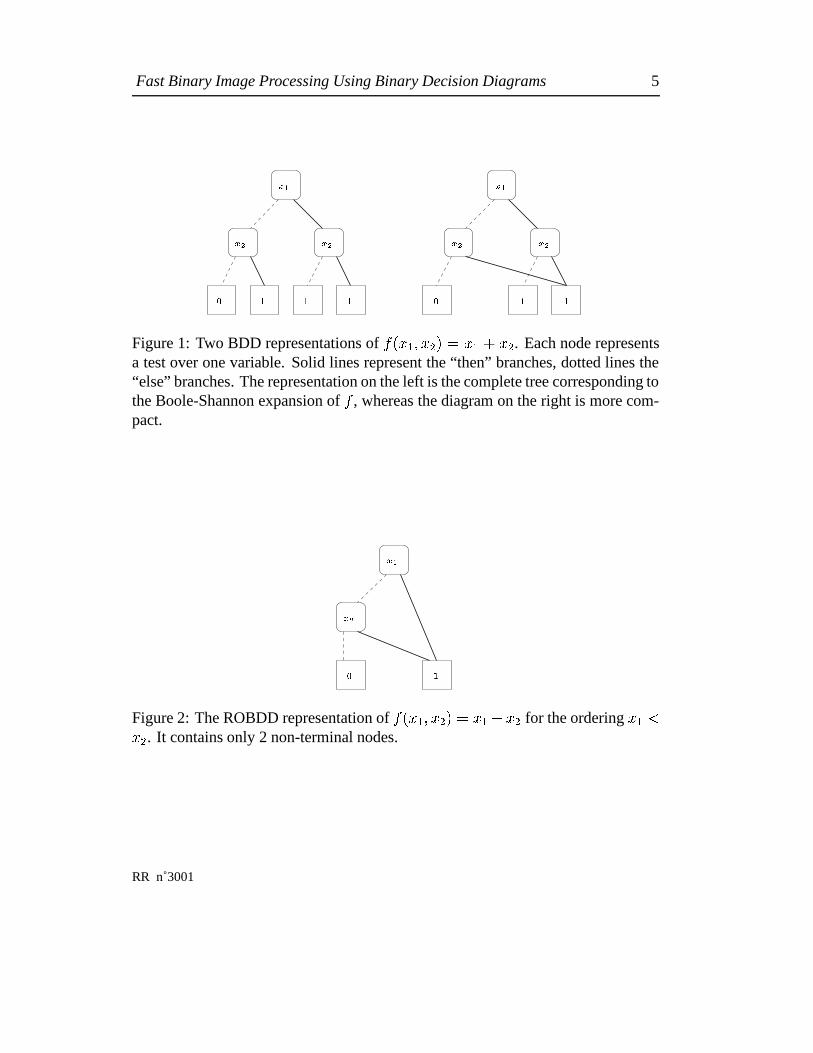
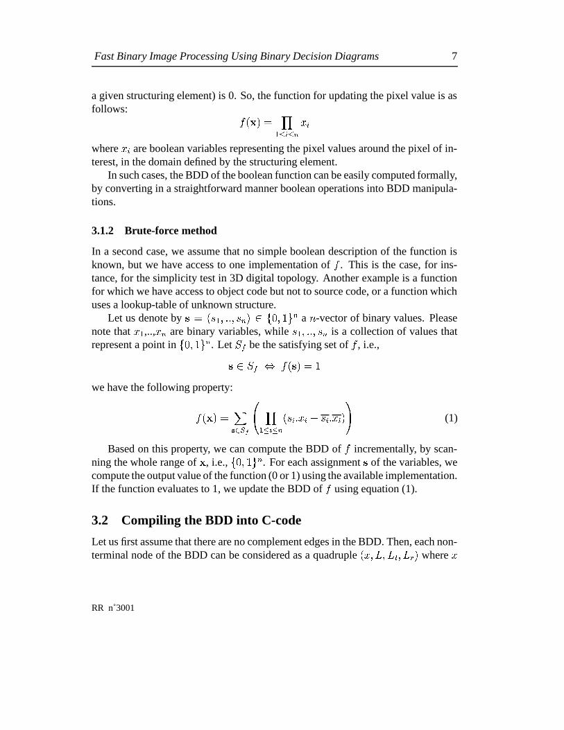
Binary Decision Diagrams are a very compact and efficient representation for sym-bolic manipulation of boolean functions. Up to now, they have been mostly used indigital-system design and finite-state system analysis [7]. Their concept was intro-duced by Lee [16] and Akers [1]. A BDD represents a boolean function ������������ �����as a directed acyclic graph, each node of which corresponds to a test of a booleanvariable ��� . Terminal nodes of the graph are the function values (0 or 1). For ins-tance, in figure 1 we show two different BDD representations of the boolean function��������������������������� (the boolean and and or are respectively denoted by and � ).
Bryant showed [7] that by imposing a fixed order on the variables and by sharingidentical sub-graphs, it was possible to reduce drastically the size of the structure.The obtained representation, called a Reduced Ordered Binary Decision Diagrams(ROBDD), is canonical. In other words, if variable ordering is fixed and reductionrules are applied, two equivalent boolean functions are guaranteed to have the sameBDD. In figure 2 we show the ROBDD for the function of figure 1.
To compact the ROBDD further, the concept of complement edges was introdu-ced [5]. A type (say, positive or negative) is assigned to each edge. The fact that anedge is negative indicates that the boolean value computed by the pointed sub-graphhas to be complemented when evaluating the function. This representation allows aformula and its negation to share the same graph. It is also canonical.
INRIA
Fast Binary Image Processing Using Binary Decision Diagrams 5
���
��� ���
�� � � �
���
� �
������
Figure 1: Two BDD representations of ��� � ��� ����� � ����� ��� . Each node representsa test over one variable. Solid lines represent the “then” branches, dotted lines the“else” branches. The representation on the left is the complete tree corresponding tothe Boole-Shannon expansion of � , whereas the diagram on the right is more com-pact.
���
� �
� �
Figure 2: The ROBDD representation of ��������� ��� � � ����� ��� for the ordering � � �
��� . It contains only 2 non-terminal nodes.
RR n˚3001

6 Luc Robert, Gregoire Malandain
From now on, by BDD we will mean “Reduced Ordered BDD with complementedges”.
From the practical standpoint, there exist a number of packages for BDD ma-nipulation. State-of-the-art BDD packages implement reduced ordered BDDs withcomplement edges, include efficient memory management packages, and allow dy-namic reordering of the input variables during BDD creation to reduce the BDDsize on the fly. They include programmatic interfaces for creating BDD functions,controlling variable ordering, and controlling memory management. For the expe-riments described in the remainder of this article, we used the package described in[6].
3 Generating fast code for a discrete function
In this section we will show how we can automatically produce an efficient imple-mentation of a given discrete function, either specified by a formal description interms of boolean operations, or induced from an implementation which may be in-efficient. We first describe how we compute a BDD representing the function. Then,we show how this BDD can be translated into efficient C-code, based on methodsused in digital system design [9, 8]. We first consider the case of a boolean function.Then, we consider the more general case of a discrete function (i.e., one which maytake a discrete set of values).
3.1 Computing the BDD corresponding to a boolean function
Let us consider a boolean function � depending on the � boolean variables ������������ ,also represented by the � -vector � � ��� ��� ��� ����� . One instance of such a function,for example, would tell if a pixel of a two-dimensional image can be removed in athinning operation, based on the values of its 8 neighbors.
3.1.1 Formal derivation
Many functions used in mathematical morphology have a direct expression in termsof boolean operations over pixel values [26]. For instance, in the case of erosion, apixel with value 1 has to be set to 0 if and only if at least one of its neighbors (for
INRIA
Fast Binary Image Processing Using Binary Decision Diagrams 7
a given structuring element) is 0. So, the function for updating the pixel value is asfollows:
��� � ��� ���� ��� � ���
where ��� are boolean variables representing the pixel values around the pixel of in-terest, in the domain defined by the structuring element.
In such cases, the BDD of the boolean function can be easily computed formally,by converting in a straightforward manner boolean operations into BDD manipula-tions.
3.1.2 Brute-force method
In a second case, we assume that no simple boolean description of the function isknown, but we have access to one implementation of � . This is the case, for ins-tance, for the simplicity test in 3D digital topology. Another example is a functionfor which we have access to object code but not to source code, or a function whichuses a lookup-table of unknown structure.
Let us denote by � � ��� �������� � ���� ����� � a � -vector of binary values. Pleasenote that � � ,.., ��� are binary variables, while ���������� � is a collection of values thatrepresent a point in �� ����� � . Let ��� be the satisfying set of � , i.e.,�������� ����� �����we have the following property:
��� � � ����! �"$#%& ���� �'� � ��� � ��� � � � ��� ��() (1)
Based on this property, we can compute the BDD of � incrementally, by scan-ning the whole range of � , i.e., �� ����� � . For each assignment � of the variables, wecompute the output value of the function (0 or 1) using the available implementation.If the function evaluates to 1, we update the BDD of � using equation (1).
3.2 Compiling the BDD into C-code
Let us first assume that there are no complement edges in the BDD. Then, each non-terminal node of the BDD can be considered as a quadruple � ���+* �+*-, �+*/.�� where �
RR n˚3001

8 Luc Robert, Gregoire Malandain
is the boolean variable tested in the node, and * �+*-,��+*/. are respectively labels assi-gned to the node and its left and right sons. The terminal nodes are assigned labelsL_TRUE and L_FALSE.
For each non-terminal node � ���+* �+* , �+*/.�� of the BDD, we can generate the fol-lowing line of C-code:
L: if ( � ) goto * , ; else goto * . ;The code corresponding to the terminal nodes is added (see example below). All
the lines are grouped into a procedure which takes as input an array of boolean va-riables, and returns a boolean value. The code corresponding to the root node of theBDD has to be executed first in the procedure. For instance, the BDD representedin figure 2 could be translated into the following function:
BOOLEAN func(BOOLEAN x[]){L_0: if ( x[0] ) goto L_TRUE; else goto L_1;L_1: if ( x[1] ) goto L_TRUE; else goto L_FALSE;L_FALSE: return BOOLEAN_0;L_TRUE: return BOOLEAN_1;
}
Another way of proceeding consists of keeping the nested structure of the BDDin the generated code. For instance, if the BDD is a binary decision tree (cf. figure 1,first case), we can trivially generate the corresponding arborescence of tests. If not(i.e. simplification rules have been applied), we can still generate the tests corres-ponding to the tree obtained by depth-first traversal of the BDD. All the edges of theBDD which do not belong to the traversal tree (i.e. those which, during the traversal,lead to already-visited nodes) are converted into goto instructions.
The BDD of figure 2 would be then translated into:
INRIA

Fast Binary Image Processing Using Binary Decision Diagrams 9
BOOLEAN func(BOOLEAN x[]){if ( x[0] )
return BOOLEAN_1;else
if ( x[1] )return BOOLEAN_1;
elsereturn BOOLEAN_0;
}
An easy optimization, actually provided by the ROBDD package, consists of re-moving the tests on the last variable.
BOOLEAN func(BOOLEAN x[]){if ( x[0] )
return BOOLEAN_1;else
return x[1];}
We can easily adapt the same translation schemes to the case of diagrams withcomplement edges. In this case, the resulting code has to keep track during the des-cent of the diagram of the traversed negative branches. For this purpose, we add abinary register
�whose initial value is false, and whose status is flipped each time a
negative edge is traversed. When reaching a node, the value of this register is true ifand only if the returned value has to be negated. Thus, for positive edges, the genera-ted lines of code are identical as above. In the case of a negative edge, a R = !R;instruction has to be executed before moving to the next test. An example of suchcode will be given in the next section.
Finding an efficient translation strategy is highly dependent on the optimizationcriterion (size of the code, computational time, etc) and on the machine on which thecode is to be run. In [9], a method for finely adapting the generated code to differentmachine architectures is presented. Using such refinements could probably allowus to produce code adapted to a given machine or architecture, and, in turn, more
RR n˚3001
10 Luc Robert, Gregoire Malandain
efficient. In the experiments presented in the remainder of the paper, we focus onone particular criterion: we try to minimize the number of accesses to image data.This is indeed one of the most penalizing operations for most architectures where asmall piece of code manipulates a large amount of data.
3.3 The case of a discrete function
In this section we show how the same scheme can be applied to generate efficientcode for discrete – not only boolean – function evaluation. Let us consider a dis-crete function depending on the vector of input boolean variables � � � �������� ����� .We assume that there are at most ��� output values. Thus, each value can be repre-sented by an assignment of
�output boolean variables, represented by the vector� � ��� ��� ����� � � .
We represent � by the characteristic function � of its graph. In other words,
� � �������� ��� ������������ � � � � � ��� � � � �
3.3.1 Computing �Computation of the BDD of � is analogous to what has been presented above: If wedenote by � � � � the value of the � th component of � � � � , we have
������������ ��� ��� ��� ����� � ��� ��� ����� �����%& ���� ��� � ��� � ��� � � � ��� �� �
������ � � �� � �������� �� � � �� ����!()(2)
We compute the BDD of � incrementally, by scanning the whole range of ��� ���������� � ,i.e., �� ����� � . For each assignment ������� ����� � � of the variables, we compute the outputvalue of the function using the available implementation, and update the BDD of �using equation (2).
3.3.2 Generating C-code
Let us assume that the BDD variable ordering is � ���������� ������������ � . Since all inputvariables appear before output variables, we obtain the configuration depicted in fi-gure 3.3.2: For a given assignment of the input variables, we follow a path of theBDD, until we reach a node which does not correspond to an input variable. This
INRIA
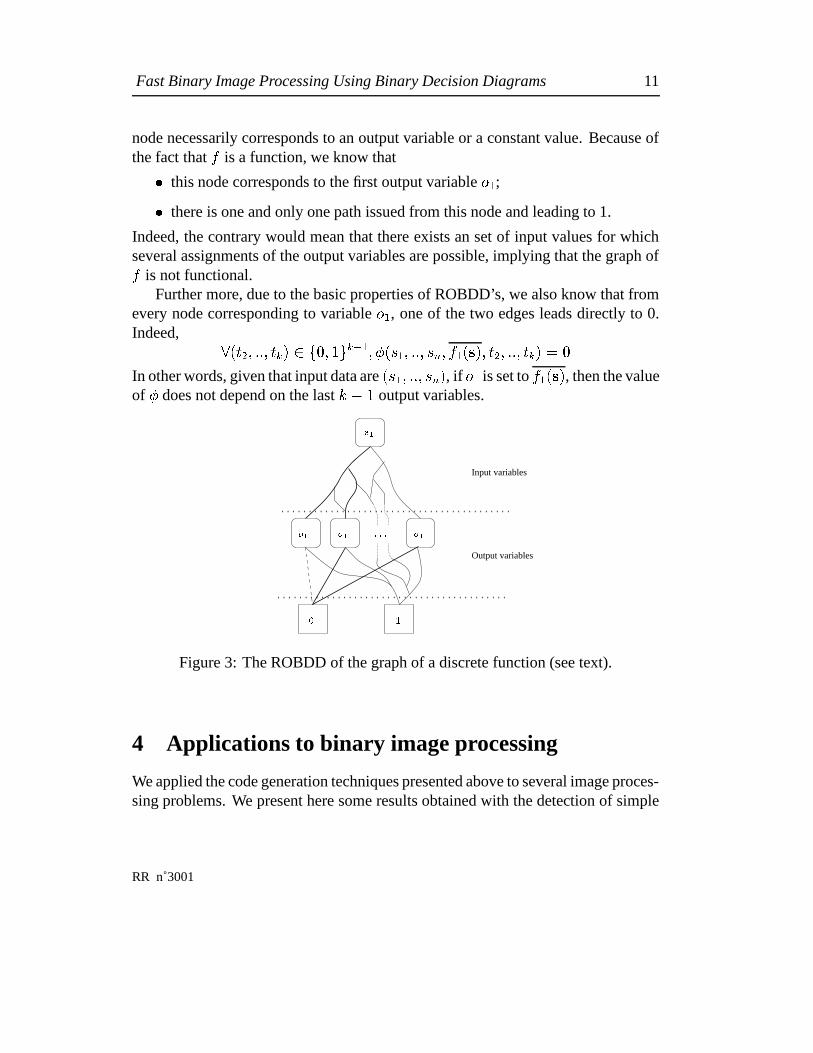
Fast Binary Image Processing Using Binary Decision Diagrams 11
node necessarily corresponds to an output variable or a constant value. Because ofthe fact that � is a function, we know that
� this node corresponds to the first output variable � � ;� there is one and only one path issued from this node and leading to 1.
Indeed, the contrary would mean that there exists an set of input values for whichseveral assignments of the output variables are possible, implying that the graph of� is not functional.
Further more, due to the basic properties of ROBDD’s, we also know that fromevery node corresponding to variable � � , one of the two edges leads directly to 0.Indeed, � ��� ������� � �- �� �$��� ��� � ��� ��� � ������ � � � � ��� ����� ������� � � � In other words, given that input data are ��� �������� ��� , if � � is set to � ��� � � , then the valueof � does not depend on the last
�� � output variables.
���
� �
Input variables
Output variables
� � ������
Figure 3: The ROBDD of the graph of a discrete function (see text).
4 Applications to binary image processing
We applied the code generation techniques presented above to several image proces-sing problems. We present here some results obtained with the detection of simple
RR n˚3001

12 Luc Robert, Gregoire Malandain
points in 2D and 3D, and the problem of thinning without shrinking in 3D. In eachcase we estimate the complexity of the generated code, in terms of the average num-ber of tests on image values. Let us first recall some basic definitions from 2D and3D digital topology [23, 13, 21, 28].
4.1 Basic definitions of digital topology
A 2D (respectively 3D) digital image � is a subset of ��� � (resp. ��� � ). A point � ��is defined by its coordinates � � ��������� (resp. � � �������� � � � ). We consider two distances:
� � ������� � �������� ������ ���� �� � � � � � ��� � �����
��� ������� � � � � ��� �!����� ���� "�#��� ���
� � � � ��� �
and the associated neighborhoods:
$ .� ��� � � � � � � � � ���%� �'&)( � ���*�$ .� ��� � � � � � ��� ������� �+&,( �
The common neighborhoods are:
in 2D 4-neighborhood:�.- ��� � � $ �� ��� �
8-neighborhood:�0/ ��� � � $ �� ��� �
in 3D 6-neighborhood:�01 ��� � � $ �� ��� �
26-neighborhood:� � 1 ��� � � $ �� ��� �
18-neighborhood:� � / ��� � � $ �� ��� ��2 $ �� � � �
We define�43� ��� � � � � ��� ��5�� � � . Two points � and � are said to be � -adjacent
if � � 3� � � � . We call the points of� 31 � � � the 6-neighbors of � .
A binary image � is defined by a binary partition of � into 6 and 6 such that672 6 �98 and 6;: 6 �<� . We call 6 the object and 6 the background.
A � -path between two points � and � of 6 (resp. 6 ) is a sequence � � � �� � ofpoints such that ��� <6 (resp. 6 ), � � � � , � � �=� , and ��� � � is � -adjacent to ���for > � � � . A subset of 6 (resp. 6 ) is said to be � -connected if a � -path canbe found between each pair of points of 6 (resp. 6 ). A � -connected component
INRIA

Fast Binary Image Processing Using Binary Decision Diagrams 13
of 6 (resp. 6 ) is a subset of 6 (resp. 6 ) which is � -connected and maximal forinclusion.
To preserve topological consistency, we have to consider different connectivitiesfor the object and the background [13]. We respectively denote them by � and � . Weconsider here that � � � � � � ��� ��� � in 2D and � ��� � � � � ��� ����� or ��� � ��� � in 3D.
4.2 Simple point
A simple point is a point whose removal does not change the topology of the binaryimage. The detection of such points is the keypoint of all thinning algorithms [13,14], thus optimizing this detection is of high interest in computer vision and imageprocessing. The detection and the characterization of 2D simple points has been al-ready widely studied. Due to the simplicity of the two-dimensional problem, seve-ral very efficient implementations have been proposed. Because of new 3D ima-ging modalities (e.g., medical imaging), the study of the 3D case is becoming moreand more important. It is also much more complex. Morgenthaler [20] proposeda first characterization of 3D simple points by using 4 local conditions. Tsao andFu [29, 13] proposed a simplified form which requires 3 local conditions. Recently,characterizations with only 2 local conditions has been found [19, 4, 25].
This last characterization [4] is based on the calculation of two numbers of connec-ted components (we consider that the object is 26-connected while the backgroundis 6-connected):
� � is simple ��� � �� � � 1�� 672 � 3� 1 � � ��� � �� � 1�� 6;2 � 3� / � � ��� � ��� (3)
�� � � 1�� 6 2 � 3� 1 ��� ��� denotes the number of 26-connected components (26-adjacentto � ) of the object 6 in
� 3� 1 ��� � , while�� � 1�� 6=2 � 3� / ��� ��� denotes the number of
6-connected components (6-adjacent to � ) of the background 6 in� 3� / � � � .
In the remainder of this section, we first present the results obtained in the simplecase of detecting 2D simple points. The interest in this case is more to demonstratethe code generation process on a well-known, simple example. Then, we present theresults obtained on the detection of 3D simple points, and the problem of thinningin 3D.
RR n˚3001

14 Luc Robert, Gregoire Malandain
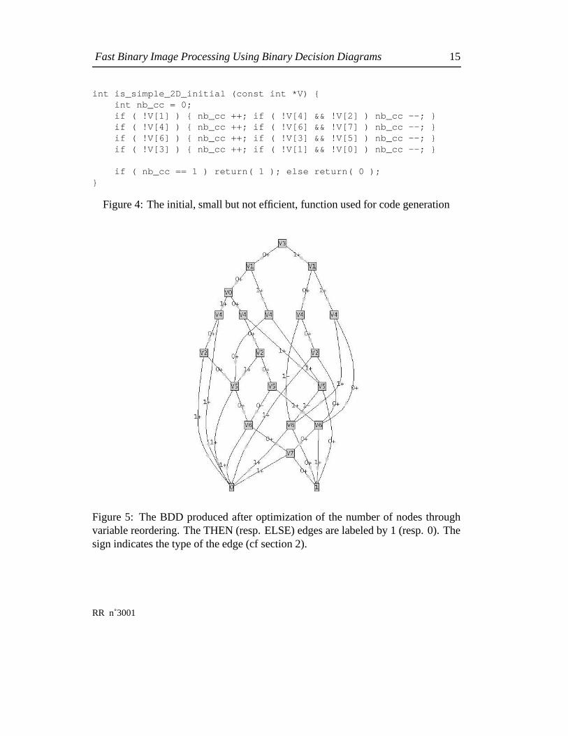
4.3 Simple points in 2D
Indexed from 0 to 7, the neighbors of a pixel are considered in the following order:NW, N, NE, W, E, SW, S, SE (i.e. from left to right, lines being considered from topto bottom). Figure 4 represents the initial – small, but not efficient – procedure usedfor BDD generation. The generated BDD is represented in figure 5. The C-codeprocedures automatically generated using the two different strategies presented insection 3.2 are displayed in figures 6 and 7. The generated code has a minimal sizeover all the potential variable orderings. Indeed, by computing all the ��� BDD’s cor-responding to all variable permutations, we checked that the variable order obtainedby applying the sifting minimization algorithm actually corresponds to a global mi-nimum for the number of nodes. Note that this exhaustive search was possible onlybecause of the small number of variables.
In table 1, we compare the numbers of tests performed by the initial function andby the generated code. Both procedures were run on the �
/potential configurations
of the input values. The table displays, for each number of tests, the correspondingnumber of configurations.
number of tests 4 5 6 7 8 9 12 averageinitial function (fig. 4) 16 64 32 64 0 64 16 7.00BDDs function (fig. 6) 144 64 32 8 8 4.72
Table 1: 2D simplicity test: comparison of the initial function with the generatedcode.
4.4 Detecting simple points in 3D
In [3], a boolean characterization of 3D simple points is given, which uses 4 booleanconditions based on local topological numbers.
A straightforward implementation of this characterization was then used to ge-nerate, using the “brute-force” approach (cf section 3.1.2), a BDD representing thefunction which returns TRUE if and only if the point is a simple point.
Computation took several hours on a Sun Sparc 20. As a result, we obtained aBDD with 1007 nodes. Using the sifting minimization algorithm, we reduced its size
INRIA
Fast Binary Image Processing Using Binary Decision Diagrams 15
int is_simple_2D_initial (const int *V) {int nb_cc = 0;if ( !V[1] ) { nb_cc ++; if ( !V[4] && !V[2] ) nb_cc --; }if ( !V[4] ) { nb_cc ++; if ( !V[6] && !V[7] ) nb_cc --; }if ( !V[6] ) { nb_cc ++; if ( !V[3] && !V[5] ) nb_cc --; }if ( !V[3] ) { nb_cc ++; if ( !V[1] && !V[0] ) nb_cc --; }
if ( nb_cc == 1 ) return( 1 ); else return( 0 );}
Figure 4: The initial, small but not efficient, function used for code generation
Figure 5: The BDD produced after optimization of the number of nodes throughvariable reordering. The THEN (resp. ELSE) edges are labeled by 1 (resp. 0). Thesign indicates the type of the edge (cf section 2).
RR n˚3001

16 Luc Robert, Gregoire Malandain
int is_simple_2D_BDD_1 (const int *V) {int R = 0;
L993: if (VAL(V,3)) {goto L929;} else {goto L656;}L929: if (VAL(V,1)) {goto L641;} else {goto L896;}L641: if (VAL(V,4)) {goto L305;} else {goto L528;}L305: if (VAL(V,6)) {goto L081;} else {goto L080;}L528: if (VAL(V,6)) {goto L080;} else {goto L337;}L337: if (VAL(V,7)) {goto L081;} else {goto L080;}L896: if (VAL(V,4)) {R=(!R);goto L305;} else {goto L625;}L625: if (VAL(V,2)) {goto L081;} else {goto L528;}L656: if (VAL(V,1)) {goto L832;} else {goto L705;}L832: if (VAL(V,4)) {goto L864;} else {goto L545;}L864: if (VAL(V,5)) {R=(!R);goto L305;} else {goto L080;}L545: if (VAL(V,5)) {goto L081;} else {goto L849;}L849: if (VAL(V,6)) {goto L081;} else {goto L337;}L705: if (VAL(V,0)) {goto L961;} else {goto L352;}L961: if (VAL(V,4)) {goto L081;} else {goto L609;}L609: if (VAL(V,2)) {goto L081;} else {goto L545;}L352: if (VAL(V,4)) {goto L864;} else {goto L769;}L769: if (VAL(V,2)) {goto L545;} else {goto L560;}L560: if (VAL(V,5)) {goto L528;} else {R=(!R);goto L849;}L080: return !R;L081: return R;
}
Figure 6: Function generated using the first scheme (see text).
to 503 nodes. Using the second strategy presented in section 3, we generated a 1500-line piece of C-code. We then compared the generated code to the initial one in termsof computational time, by evaluating the function over all the potential variable ( � �
1)
assignements.A first comparison between the straightforward implementation of the boolean
characterization and the generated code is given in table 2. Histograms of the num-bers of tests are given in figure 8. Table 3 shows the average time required for onefunction evaluation on several architectures.
minimum average maximumnumber of tests number of tests number of tests
bool. charac. of [3] 6 111.41 176bool. func. (BDDs) 6 8.71 26
Table 2: Comparison of the generated code with the boolean characterization of [3]for the 3D simplicity test over the � �
1potential neighborhoods.
INRIA

Fast Binary Image Processing Using Binary Decision Diagrams 17
int is_simple_2D_BDD_2 (const int *V) {int R = 0;if ( V[3] )if ( V[1] )
if ( V[4] )return ( V[6] ? R : !R ) ;
elseLbl0: if ( V[6] )
return ( !R ) ;elsereturn ( V[7] ? R : !R ) ;
elseif ( V[4])
return ( V[6] ? !R : R ) ;elseif ( V[2] )
return ( R ) ;else{ goto Lbl0; }
elseif ( V[1] )
if ( V[4] )Lbl1: if ( V[5] )
return ( V[6] ? !R : R ) ;elsereturn ( !R ) ;
elseLbl2: if ( V[5] )
return ( R ) ;elseLbl3: if ( V[6] )return ( R ) ;
elsereturn ( V[7] ? R : !R ) ;
elseif ( V[0] )
if ( V[4] )return ( R ) ;
elseif ( V[2] )return ( R ) ;
else{goto Lbl2;}
elseif ( V[4] )
{goto Lbl1;}else
if ( V[2] ){goto Lbl2;}
elseif ( V[5] )
{goto Lbl0;}else{R= !R;goto Lbl3;}
}
Figure 7: Function generated using the second scheme (see text).
RR n˚3001

18 Luc Robert, Gregoire Malandain
Machine characteristics Time ( � sec)SUN Ultra1 Sparc, 167MHz, SUNOS5.5 0.211
SGI Indy IP22, 150MHz, IRIX5.3 0.45DEC Alpha 3000, 166MHz, OSF1V3.2 0.276
Table 3: Average time for one function evaluation (see text).
0.0 50.0 100.0 150.00.0
2000000.0
4000000.0
6000000.0
0.0 10.0 20.0 30.00.0
5000000.0
10000000.0
15000000.0
Figure 8: Histograms of the numbers of tests needed to evaluate the 3D simplicitytest over the � �
1possible neighborhoods. Left: boolean characterization [3]. Right:
code produced using BDD’s.
INRIA
Fast Binary Image Processing Using Binary Decision Diagrams 19
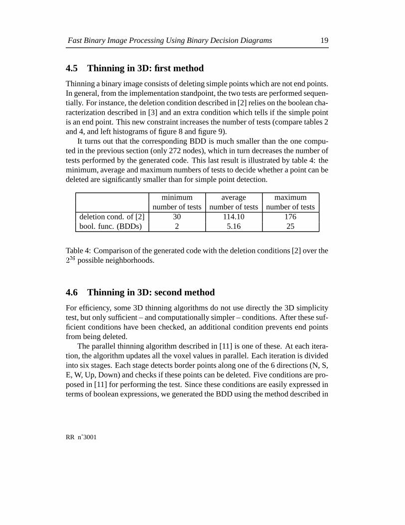
4.5 Thinning in 3D: first method
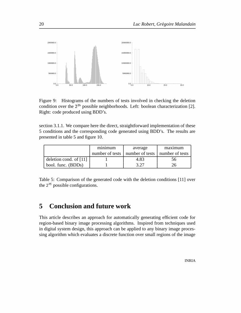
Thinning a binary image consists of deleting simple points which are not end points.In general, from the implementation standpoint, the two tests are performed sequen-tially. For instance, the deletion condition described in [2] relies on the boolean cha-racterization described in [3] and an extra condition which tells if the simple pointis an end point. This new constraint increases the number of tests (compare tables 2and 4, and left histograms of figure 8 and figure 9).
It turns out that the corresponding BDD is much smaller than the one compu-ted in the previous section (only 272 nodes), which in turn decreases the number oftests performed by the generated code. This last result is illustrated by table 4: theminimum, average and maximum numbers of tests to decide whether a point can bedeleted are significantly smaller than for simple point detection.
minimum average maximumnumber of tests number of tests number of tests
deletion cond. of [2] 30 114.10 176bool. func. (BDDs) 2 5.16 25
Table 4: Comparison of the generated code with the deletion conditions [2] over the� �1
possible neighborhoods.
4.6 Thinning in 3D: second method
For efficiency, some 3D thinning algorithms do not use directly the 3D simplicitytest, but only sufficient – and computationally simpler – conditions. After these suf-ficient conditions have been checked, an additional condition prevents end pointsfrom being deleted.
The parallel thinning algorithm described in [11] is one of these. At each itera-tion, the algorithm updates all the voxel values in parallel. Each iteration is dividedinto six stages. Each stage detects border points along one of the 6 directions (N, S,E, W, Up, Down) and checks if these points can be deleted. Five conditions are pro-posed in [11] for performing the test. Since these conditions are easily expressed interms of boolean expressions, we generated the BDD using the method described in
RR n˚3001
20 Luc Robert, Gregoire Malandain
0.0 50.0 100.0 150.00.0
500000.0
1000000.0
1500000.0
2000000.0
0.0 10.0 20.0 30.00.0
5000000.0
10000000.0
15000000.0
20000000.0
Figure 9: Histograms of the numbers of tests involved in checking the deletioncondition over the � �
1possible neighborhoods. Left: boolean characterization [2].
Right: code produced using BDD’s.
section 3.1.1. We compare here the direct, straightforward implementation of these5 conditions and the corresponding code generated using BDD’s. The results arepresented in table 5 and figure 10.
minimum average maximumnumber of tests number of tests number of tests
deletion cond. of [11] 1 4.83 56bool. func. (BDDs) 1 3.27 26
Table 5: Comparison of the generated code with the deletion conditions [11] overthe � �
1possible configurations.
5 Conclusion and future work
This article describes an approach for automatically generating efficient code forregion-based binary image processing algorithms. Inspired from techniques usedin digital system design, this approach can be applied to any binary image proces-sing algorithm which evaluates a discrete function over small regions of the image
INRIA

Fast Binary Image Processing Using Binary Decision Diagrams 21
0.0 20.0 40.0 60.00.0
10000000.0
20000000.0
30000000.0
0.0 10.0 20.0 30.00.0
5000000.0
10000000.0
15000000.0
20000000.0
25000000.0
30000000.0
35000000.0
Figure 10: Histograms of the number of tests needed to determine if a point canbe deleted [11] over the � �
1possible configurations. Left: direct implementation.
Right: code produced using BDD’s.
(e.g., discrete morphological and topological operations). Given a description of thefunction in terms of either boolean formulae or a compiled module, it automaticallyproduces a program which implements the function. The generated C source code isportable and compact. It is also very efficient: at each stage of its execution, the pro-cedure is guaranteed to examine only the pertinent input data, i.e., the values whichaffect the result. For each such value, it performs at most one test, one branchingand one binary register operation.
We applied our method to several binary image processing tasks, such as the 2Dand 3D simplicity tests, and two different 3D thinning processes. In each case, weproduced functions more efficient than the previously optimized implementations,reducing the execution time by a factor of up to 20.
There remain a number of directions still to be explored. First, there exist manyother image processing applications in which the technique described in this papercan be directly applied (edges tracking, classification of corners and junctions, etc).Second, more efficiency can be reached by studying more carefully the distributionof the incoming data (depending on the type of images or or the algorithm) and ta-king it into consideration when optimizing the BDD. Third, a better knowledge ofthe various efficient data structures used in digital design would probably help us ad-dress other image processing tasks, or deal with other kinds of images (grey-level,floating-point).
RR n˚3001

22 Luc Robert, Gregoire Malandain
We are convinced that there remains a lot to gain in bringing the power of struc-tures such as BDD’s to the domains of computer vision and image analysis.
Acknowledgements
We would like to thank Ellen Sentovitch for all the precious informations about BDD’s.Also, she carefully read previous versions of the paper and gave us lots of valuablecomments. Thanks to Gerard Berry for helpful discussions.
References
[1] S.B. Akers. Binary decision diagrams. IEEE Transactions on Computers,C(27):509–516, June 1978.
[2] G. Bertrand. A parallel thinning algorithm for medial surfaces. Pattern Reco-gnition Letters, 16:979–986, 1995.
[3] G. Bertrand. Boolean characterization of 3D simple points. Pattern Recogni-tion Letters, 17:115–124, 1996.
[4] G. Bertrand and G. Malandain. A new characterization of three-dimensionalsimple points. Pattern Recognition Letters, 15(2):169–175, February 1994.
[5] J.-P. Billon. Perfect normal forms for discrete functions. Research Report87019, BULL, March 1987.
[6] K.S. Brace, R.L. Rudell, and R.E. Bryant. Efficient implementation of a bddpackage. In Proc. of the 27th IEEE Design Automation Conference, pages 40–45, Orlando, Fl., June 1990.
[7] R.E. Bryant. Symbolic boolean manipulation with ordered binary-decision dia-grams. ACM Computing Surveys, 24(3):293–317, September 1992.
[8] C. Castelluccia and W. Dabbous. Hippco: A high performance protocol codeoptimizer. Research Report 2478, INRIA, December 1995.
INRIA

Fast Binary Image Processing Using Binary Decision Diagrams 23
[9] M. Chiodo, P. Giusto, A. Jurecska, L. Lavagno, H. Hsieh, A. Sangiovanni-Vincentelli, and E. Sentovich. Synthesis of software programs for embeddedcontrol applications. In Proc. ��� ��� Design Automation Conference, June 1995.
[10] Gerard Giraudon. A efficient edge following algorithm. In 5th ScandinavianConference on Image Analysis, Stockholm, June 1987.
[11] W.X. Gong and G. Bertrand. A simple parallel 3-D thinning algorithm. In 10thInternational Conference on Pattern Recognition, Atlantic City, June 17–211990.
[12] R.W. Hall and C.-Y. Hu. Time-efficient compuattion of 3d topological func-tions. Pattern Recognition Letters, 17:1017–1033, 1996.
[13] T.Y. Kong and A. Rosenfeld. Digital topology: introduction and survey. Com-puter Vision, Graphics, and Image Processing, 48:357–393, 1989.
[14] L. Lam, S.-W. Lee, and C. Y. Suen. Thinning Methodologies – A Comprehen-sive Survey. IEEE Transactions on Pattern Analysis and Machine Intelligence,14(9):869–885, september 1992.
[15] L. Latecki and C.C. Ma. An algorithm for a 3d simplicity test. Computer Visionand Image Understanding, 63(2):388–393, March 1996.
[16] C.Y. Lee. Representation of switching functions by binary decision programs.Bell Systems Technical Journal, (38):985–999, 1959.
[17] T.-C. Lee, R.L. Kashyap, and C.-N. Chu. Building skeleton models via 3-dmedial surface/axis thinning algorithms. Computer Vision and Image Unders-tanding, 56(6):462–478, November 1994.
[18] G. Malandain and G. Bertrand. Fast characterization of 3-D simple points. In11th International Conference on Pattern Recognition, The Hague, The Ne-therlands, August 30 – September 3 1992. IAPR.
[19] G. Malandain, G. Bertrand, and N. Ayache. Topological segmentation ofdiscrete surfaces. International Journal of Computer Vision, 10(2):183–197,1993.
RR n˚3001

24 Luc Robert, Gregoire Malandain
[20] D.G. Morgenthaler. Three-dimensional simple points: serial erosion, parallelthinning, and skeletonization. Tr–1005, Computer Science Center, Universityof Maryland, College Park, MD 20742, U.S.A., February 1981.
[21] A. Nakamura and K. Aizawa. On the recognition of properties of three-dimensional pictures. IEEE Transactions on Pattern Analysis and MachineIntelligence, 6:708–713, November 1985.
[22] M. Otte and H.-H Nagel. Extraction of line drawings from gray value imagesby non-local analysis of edge element structures. In G. Sandini, editor, Pro-ceedings of the 2nd European Conference on Computer Vision, volume 588 ofLecture Notes in Computer Science, pages 687–695, Santa Margherita Ligure,Italy, May 1992. Springer-Verlag.
[23] A. Rosenfeld. Three-dimensional digital topology. Tr–936, Computer ScienceCenter, University of Maryland, College Park, MD 20742, U.S.A., September1980.
[24] P.K. Saha and B.B. Chaudhuri. 3d digital topology under binary transformationwith applications. Computer Vision and Image Understanding, 63(3):418–429,1996.
[25] P.K. Saha, B.B. Chaudhuri, B. Chanda, and D.D. Majumder. Topology preser-vation in 3D digital space. Pattern Recognition, 27(2):295–300, 1994.
[26] J. Serra. Image analysis and mathematical morphology, volume 1. AcademicPress, 1982.
[27] J. Serra. Image analysis and mathematical morphology: theoretical advances,volume 2. Academic Press, 1988.
[28] J.I. Toriwaki, S. Yokoi, T. Yonekura, and T. Fukumura. Topological propertiesand topology-preserving transformation of a three-dimensional binary picture.In 6th International Conference on Pattern Recognition, pages 414–419, Mu-nich, October 1982.
[29] Y.F. Tsao and K.S. Fu. A 3-D parallel skeletonization thinning algorithm. IEEEPRIP Conference, pages 678–683, 1982.
INRIA

Unite de recherche INRIA Lorraine, Technopole de Nancy-Brabois, Campus scientifique,615 rue du Jardin Botanique, BP 101, 54600 VILLERS LES NANCY
Unite de recherche INRIA Rennes, Irisa, Campus universitaire de Beaulieu, 35042 RENNES CedexUnite de recherche INRIA Rhone-Alpes, 655, avenue de l’Europe, 38330 MONTBONNOT ST MARTIN
Unite de recherche INRIA Rocquencourt, Domaine de Voluceau, Rocquencourt, BP 105, 78153 LE CHESNAY CedexUnite de recherche INRIA Sophia-Antipolis, 2004 route des Lucioles, BP 93, 06902 SOPHIA-ANTIPOLIS Cedex
EditeurINRIA, Domaine de Voluceau, Rocquencourt, BP 105, 78153 LE CHESNAY Cedex (France)
ISSN 0249-6399