Fast and Reliable Collision Culling using Graphics Hardware
8
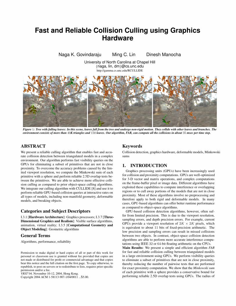
Fast and Reliable Collision Culling using Graphics Hardware Naga K. Govindaraju Ming C. Lin Dinesh Manocha University of North Carolina at Chapel Hill {naga, lin, dm}@cs.unc.edu http://gamma.cs.unc.edu/RCULLIDE Figure 1: Tree with falling leaves: In this scene, leaves fall from the tree and undergo non-rigid motion. They collide with other leaves and branches. The environment consists of more than 40K triangles and 150 leaves. Our algorithm, FAR, can compute all the collisions in about 35 msec per time step. ABSTRACT We present a reliable culling algorithm that enables fast and accu- rate collision detection between triangulated models in a complex environment. Our algorithm performs fast visibility queries on the GPUs for eliminating a subset of primitives that are not in close proximity. To overcome the accuracy problems caused by the lim- ited viewport resolution, we compute the Minkowski sum of each primitive with a sphere and perform reliable 2.5D overlap tests be- tween the primitives. We are able to achieve more effective colli- sion culling as compared to prior object-space culling algorithms. We integrate our culling algorithm with CULLIDE [8] and use it to perform reliable GPU-based collision queries at interactive rates on all types of models, including non-manifold geometry, deformable models, and breaking objects. Categories and Subject Descriptors I.3.1 [Hardware Architecture]: Graphics processors; I.3.7 [Three- Dimensional Graphics and Realism]: Visible surface algorithms, animation, virtual reality; I.3.5 [Computational Geometry and Object Modeling]: Geometric algorithms General Terms Algorithms, performance, reliability Permission to make digital or hard copies of all or part of this work for personal or classroom use is granted without fee provided that copies are not made or distributed for profit or commercial advantage and that copies bear this notice and the full citation on the first page. To copy otherwise, to republish, to post on servers or to redistribute to lists, requires prior specific permission and/or a fee. VRST’04, November 10-12, 2004, Hong Kong. Copyright 2004 ACM 1-58113-907-1/04/0011 ...$5.00. Keywords Collision detection, graphics hardware, deformable models, Minkowski sums 1. INTRODUCTION Graphics processing units (GPUs) have been increasingly used for collision and proximity computations. GPUs are well-optimized for 3-D vector and matrix operations, and complex computations on the frame-buffer pixel or image data. Different algorithms have exploited these capabilities to compute interference or overlapping regions or to cull away portions of the models that are not in close proximity. Most of these algorithms involve no preprocessing and therefore apply to both rigid and deformable models. In many cases, GPU-based algorithms can offer better runtime performance as compared to object-space algorithms. GPU-based collision detection algorithms, however, often suf- fer from limited precision. This is due to the viewport resolution, sampling errors, and depth precision errors. For example, current GPUs provide a viewport resolution of 2K × 2K pixels, which is equivalent to about 11 bits of fixed-precision arithmetic. The low precision and sampling errors can result in missed collisions between two objects. In contrast, object-space collision detection algorithms are able to perform more accurate interference compu- tations using IEEE 32 or 64-bit floating arithmetic on the CPUs. Main Results: We present a simple and efficient algorithm FAR for fast and reliable collision culling between triangulated models in a large environment using GPUs. We perform visibility queries to eliminate a subset of primitives that are not in close proximity, thereby reducing the number of pairwise tests that are performed for exact proximity computation. We show that the Minkowski sum of each primitive with a sphere provides a conservative bound for performing reliable 2.5D overlap tests using GPUs. The radius of
Transcript of Fast and Reliable Collision Culling using Graphics Hardware
Fast and Reliable Collision Culling using GraphicsHardware
Naga K. Govindaraju Ming C. Lin Dinesh Manocha
University of North Carolina at Chapel Hill{naga, lin, dm}@cs.unc.eduhttp://gamma.cs.unc.edu/RCULLIDE
Figure 1: Tree with falling leaves: In this scene, leaves fall from the tree and undergo non-rigid motion. They collide with other leaves and branches. Theenvironment consists of more than 40K triangles and 150 leaves. Our algorithm, FAR, can compute all the collisions in about 35 msec per time step.
ABSTRACTWe present a reliable culling algorithm that enables fast and accu-rate collision detection between triangulated models in a complexenvironment. Our algorithm performs fast visibility queries on theGPUs for eliminating a subset of primitives that are not in closeproximity. To overcome the accuracy problems caused by the lim-ited viewport resolution, we compute the Minkowski sum of eachprimitive with a sphere and perform reliable 2.5D overlap tests be-tween the primitives. We are able to achieve more effective colli-sion culling as compared to prior object-space culling algorithms.We integrate our culling algorithm with CULLIDE [8] and use it toperform reliable GPU-based collision queries at interactive rates onall types of models, including non-manifold geometry, deformablemodels, and breaking objects.
Categories and Subject DescriptorsI.3.1 [Hardware Architecture]: Graphics processors; I.3.7 [Three-Dimensional Graphics and Realism]: Visible surface algorithms,animation, virtual reality; I.3.5 [Computational Geometry andObject Modeling]: Geometric algorithms
General TermsAlgorithms, performance, reliability
Permission to make digital or hard copies of all or part of this work forpersonal or classroom use is granted without fee provided that copies arenot made or distributed for profit or commercial advantage and that copiesbear this notice and the full citation on the first page. To copy otherwise, torepublish, to post on servers or to redistribute to lists, requires prior specificpermission and/or a fee.VRST’04, November 10-12, 2004, Hong Kong.Copyright 2004 ACM 1-58113-907-1/04/0011 ...$5.00.
KeywordsCollision detection, graphics hardware, deformable models, Minkowskisums
1. INTRODUCTIONGraphics processing units (GPUs) have been increasingly used
for collision and proximity computations. GPUs are well-optimizedfor 3-D vector and matrix operations, and complex computationson the frame-buffer pixel or image data. Different algorithms haveexploited these capabilities to compute interference or overlappingregions or to cull away portions of the models that are not in closeproximity. Most of these algorithms involve no preprocessing andtherefore apply to both rigid and deformable models. In manycases, GPU-based algorithms can offer better runtime performanceas compared to object-space algorithms.
GPU-based collision detection algorithms, however, often suf-fer from limited precision. This is due to the viewport resolution,sampling errors, and depth precision errors. For example, currentGPUs provide a viewport resolution of 2K × 2K pixels, whichis equivalent to about 11 bits of fixed-precision arithmetic. Thelow precision and sampling errors can result in missed collisionsbetween two objects. In contrast, object-space collision detectionalgorithms are able to perform more accurate interference compu-tations using IEEE 32 or 64-bit floating arithmetic on the CPUs.Main Results: We present a simple and efficient algorithm FARfor fast and reliable collision culling between triangulated modelsin a large environment using GPUs. We perform visibility queriesto eliminate a subset of primitives that are not in close proximity,thereby reducing the number of pairwise tests that are performedfor exact proximity computation. We show that the Minkowski sumof each primitive with a sphere provides a conservative bound forperforming reliable 2.5D overlap tests using GPUs. The radius of

the sphere is a function of viewport resolution and depth bufferprecision. For each geometric primitive (a collection of triangles),our algorithm computes a tight bounding offset representation. Thebounding offset representation is a union of object-oriented bound-ing boxes (UOBB) where each OBB encloses a single triangle. Ouralgorithm performs visibility queries using these UOBBs on GPUsto reject primitives that are not in close proximity. Overall, our al-gorithm guarantees that no collisions will be missed due to limitedframebuffer precision or quantization errors during rasterization.
The key advantages of our approach are:
• More reliable computations over prior GPU-based methods;
• More effective culling over existing CPU-based algorithms;
• Broad applicability to non-manifold geometry, deformablemodels, and breaking objects;
• Interactive performance with no preprocessing and low mem-ory overhead.
We have combined our culling algorithm with CULLIDE [8] toperform collision detection in complex environments. We utilizethe GPU for fast and reliable pruning of primitive pairs and per-form exact interference tests on the CPU. We have implementedthis collision culling algorithm on a Pentium IV PC with NVIDIAGeForce FX 5950 card. We are able to perform interactive collisiondetection between complex objects composed of tens of thousandsof triangles that undergo rigid and non-rigid motion, including frac-turing and deformation.Organization: The rest of the paper is organized in the follow-ing manner. In Sec. 2, we give a brief overview of related work incollision detection. We present sufficient conditions for eliminat-ing image-based sampling errors in Sec. 3. In Sec. 4, we presentdetails for fast computation of bounding offset representations andour conservative culling algorithm. We describe its implementationin Sec. 5 and highlight its performance on different environments.Finally, we analyze our algorithm and describe some of its limita-tions in Sec. 6.
2. RELATED WORKThe problem of collision detection has been well studied for
more than three decades. See recent surveys in [19] and [14] for anoverview. Prior algorithms for collision detection between triangu-lated models can be classified into three broad categories: object-space culling, image-space intersection computation, and hybridapproaches.Object-space culling: Most of the commonly used techniques toaccelerate collision detection between two objects utilize spatialdata structures, including spatial partitioning and bounding volumehierarchies. Some of the commonly used bounding volume hierar-chies include sphere-trees [13, 26], AABB-trees [5, 25], OBB-trees[7, 4], k-DOP-trees [11, 17], etc. These representations are used tocull away portions of each object that are not in close proximity.Typically, these representations are built in a pre-processing stageto accelerate runtime queries. In practice, they work well for rigidobjects. However, the overhead of recomputing the hierarchy onthe fly for deformable models can be quite significant [2, 12].Image-space interference computation: Several algorithms haveused graphics hardware for interference and collision computations[2, 3, 9, 10, 12, 18, 23, 28, 29, 31]. These algorithms requireno preprocessing; they work well on commodity GPUs. However,they have some limitations. First, they can detect a collision up to
viewport resolution. The accuracy of collision detection also variesbased on the relative distance between the objects, i.e. collisionqueries are less accurate if the objects are separated by distancesgreater than their average size. Second, most of these algorithmsneed to read back the color or depth buffer contents for further pro-cessing and readbacks can be slow on current graphics systems [18,8]. There exists software implementations for reliable interferencedetection using fat edges and readback multiple depth layers [28],but they work well only on scenes with two objects and few con-tacts. Also, [28] does not address the issue of aliasing in depthbuffer. This limitation is addressed in [27] and used for renderingimage-precision silhouette edges. [27] fatten the back-facing poly-gons for rendering silhouette edges. The front-facing polygons arenot fattened as the technique only renders silhouette edges. Assome polygons are not fattened, the technique described in [27]may miss interferences due to limited image precision.Hybrid methods: Hybrid algorithms combine some of the ben-efits of the object-space and image-space approaches. Kim et al.[16] compute the closest distance from a point to the union of con-vex polytopes using the GPU, refining the answer on the CPU.Govindaraju et al. [8] use occlusion queries on the GPU to cullaway objects that are not colliding with others. Heidelberger etal. [10] compute layer depth images (LDIs) on the GPU, use theLDIs for explicit computation of the intersection volumes betweentwo closed objects, and perform vertex-in-volume tests. In all thesecases, GPU-based techniques are used to accelerate the overall com-putation. However, viewport resolution governs the accuracy ofthese algorithms.
3. RELIABLE CULLING USING GPUSIn this section, we present our culling algorithm that performs
visibility queries on GPUs and culls away primitives that are notin close proximity. We also analyze the sampling problems causedby limited viewport resolution and present a sufficient condition toperform conservative and reliable culling.
3.1 Overlap Tests
Figure 2: In this figure, the objects are not colliding. Using view 1, wedetermine a separating surface with unit depth complexity along the viewand conclude from the existence of such a surface that the objects arenot colliding. This is a sufficient but not a necessary condition. Observethat in view 2, there does not exist a separating surface with unit depthcomplexity but the objects are not interfering.
Interference computation algorithms employ GPUs to performeither 2D overlap tests using color and stencil buffers or 2.5D over-lap tests with additional depth information. The 2.5D overlap testsare less conservative and can be performed using occlusion querieson current graphics processors [8].
Visibility-based overlap tests: Govindaraju et al. [8] performvisibility computations to check whether two primitives, P1 and

P2, overlap. The approach chooses a view direction and checkswhether P1 is fully visible with respect to P2 along that direction.If P1 is fully visible then there exists a separating surface betweenP1 and P2. We call this the visibility-based-overlap (VO) query,which provides a sufficient condition that the two primitives do notoverlap and is illustrated in Fig. 2. The VO query is performed ef-ficiently on GPUs. Using three or less mutually orthogonal ortho-graphic views, many complex objects that are in close proximity(as shown in Fig. 2) can be pruned. However, due to limited view-port and frame buffer resolution, VO queries can miss collisionsand this problem is typical of any GPU-based interference detec-tion algorithm. Our goal is to develop reliable VO queries on theGPUs for efficiently pruning complex configurations as shown inFig 2, without missing any collisions.
CULLIDE: We now briefly describe CULLIDE [8] which per-forms VO queries between multiple objects and computes a po-tentially colliding set (PCS) of objects. Given n objects that arepotentially colliding P1, ..., Pn, Govindaraju et al. [8] describe alinear time two-pass rendering algorithm to test if an object Pi isfully visible against the remaining objects, along a view direction.The algorithm uses occlusion queries to test if an object is fullyvisible or not. To test if an object P is fully visible against a set ofobjects S, CULLIDE first renders S into the frame buffer. Next, itsets the depth function to GL GEQUAL and disables depth writes.The object P is rendered using an occlusion query. If the pixel passcount returned by occlusion query is zero, then the object P is fullyvisible and therefore, does not collide with S. Using this formula-tion, Govindaraju et al. [8] prune objects Pi that do not overlapwith other objects in the environment. The algorithm begins withempty frame buffer and proceeds in two passes as follows:
In the first pass, CULLIDE rasterizes the primitives in the orderP1, ..., Pn testing if they are fully visible. In this pass, if a primi-tive Pi is fully visible, then it does not intersect any of the objectsP1, ..., Pi−1. In the second pass, it performs the same operationsbut renders the primitives in the order Pn, .., P1. In this pass, ifa primitive Pi is fully visible, then it does not intersect any of theobjects Pn, .., Pi+1. At the end of two passes, if a primitive is fullyvisible in both the passes, the primitive does not interfere with theremaining primitives and is removed from the PCS. The view direc-tions are chosen along the world-space axes and collision culling isperformed using orthographic projections.
3.2 Sampling ErrorsWe define the notation used in the rest of paper and the issues in
performing interference detection on GPUs.
Orthographic projection: Let A be an axis, where A∈ {X, Y, Z}and, Amin and Amax define the lower and upper bounds on P1
and P2 along A’s direction in 3D. Let RES(A) define the resolutionalong an axis. The viewport resolution of a GPU is RES(X) ×RES(Y ) (e.g. 211 × 211) and the depth buffer precision is RES(Z)(e.g. 224).
Let O be an orthographic projection with bounds(Xmin, Xmax, Ymin, Ymax, Zmin, Zmax) on the 3D primitives.The dimension of the grid along an axis in 3D is given by dA
where dA = Amax−Amin
RES(A). Rasterization of a primitive under or-
thographic projection performs linear interpolation of the vertex co-ordinates of each primitive and maps each point on a primitive tothe 3D grid. This mapping is based on sampling of a primitive atfixed locations in the grid. When we rasterize the primitives to per-form VO queries, many errors arise due to sampling. There arethree types of errors:1. Projective and perspective aliasing errors: These errors can
result in some of the primitives not getting rasterized. This errormay result in an incorrect answer to the VO query.2. Image sampling errors: We can miss interferences betweentriangles due to sampling at the fixed locations. In this case, eachtriangle is sampled but the intersection set of the triangles is notsampled (see Fig. 3).3. Depth-buffer precision errors: If the distance between twoprimitives is less than RES(Z), VO query may not be able to ac-curately compute whether one is fully visible with respect to theother.
3.3 Reliable VO QueriesWe can overcome the errors described in Section 3.2 by gen-
erating a “fattened” representation T B for each triangle T . If atriangle T interferes with a set of primitives S within a pixel, wemay miss interferences because the triangle is inaccurately classi-fied fully visible due to the following possibilities:
• Error 1: a fragment is not generated when rasterizing T orS.
• Error 2: a fragment is generated but does not sample theinterfering points within the pixel.
• Error 3: a fragment is generated and samples the interfer-ing points within a pixel but the precision of frame or depthbuffer is not sufficient.
These errors correspond to the three types of errors discussed inSection 3.2. Our approach solves these problems using “fattened”representations of triangles that
• Generates at least two fragments for each pixel touched 1 bya triangle.
• For each pixel touched by a triangle, the depth of the corre-sponding two fragments bound the depth of all points of thetriangle that project inside the pixel.
Using a closed fattened representation T B for each triangle T inCULLIDE provides a sufficient condition for eliminating the sam-pling and precision errors. Suppose two primitives T1 and T2 inter-sect at some point within a pixel X that may or may not be sampled.Then T B
1 is not fully visible with respect to T B2 as rasterization of
T B1 generates two fragments corresponding to X and at least one
of the two fragments fails the depth test. Similarly, T B2 is not fully
visible with respect to T B1 . Therefore, neither T1 nor T2 is pruned
from the PCS. In the rest of the section, we formally prove that fora given orthographic view, the Minkowski sum of a bounding cubeB centered at the origin with T provides a conservative fattenedrepresentation T B and eliminates sampling or precision errors ir-respective of the sampling strategy. The size of the bounding cubeB is a function of the world space pixel dimensions and in prac-tice, is very small. Therefore, P B is a very tight fit to the originalgeometric primitive P .
Our algorithm does not make any assumptions about samplingthe primitives within a pixel. We compute an axis-aligned bound-ing box B with dimension p where p = max(2∗dX , 2∗dY , 2∗dZ)centered at the origin. In practice, this bound may be conserva-tive. If a GPU uses some uniform supersampling algorithm duringrasterization, p can be further reduced. For example, if the GPUsamples each pixel in the center, then p can be reduced by half.
Let B be an axis-aligned cube centered at the origin with dimen-sion p. Given two primitives, P1 and P2, let Q be a point on their1A pixel is touched by a triangle if some point of the triangleprojects inside the pixel
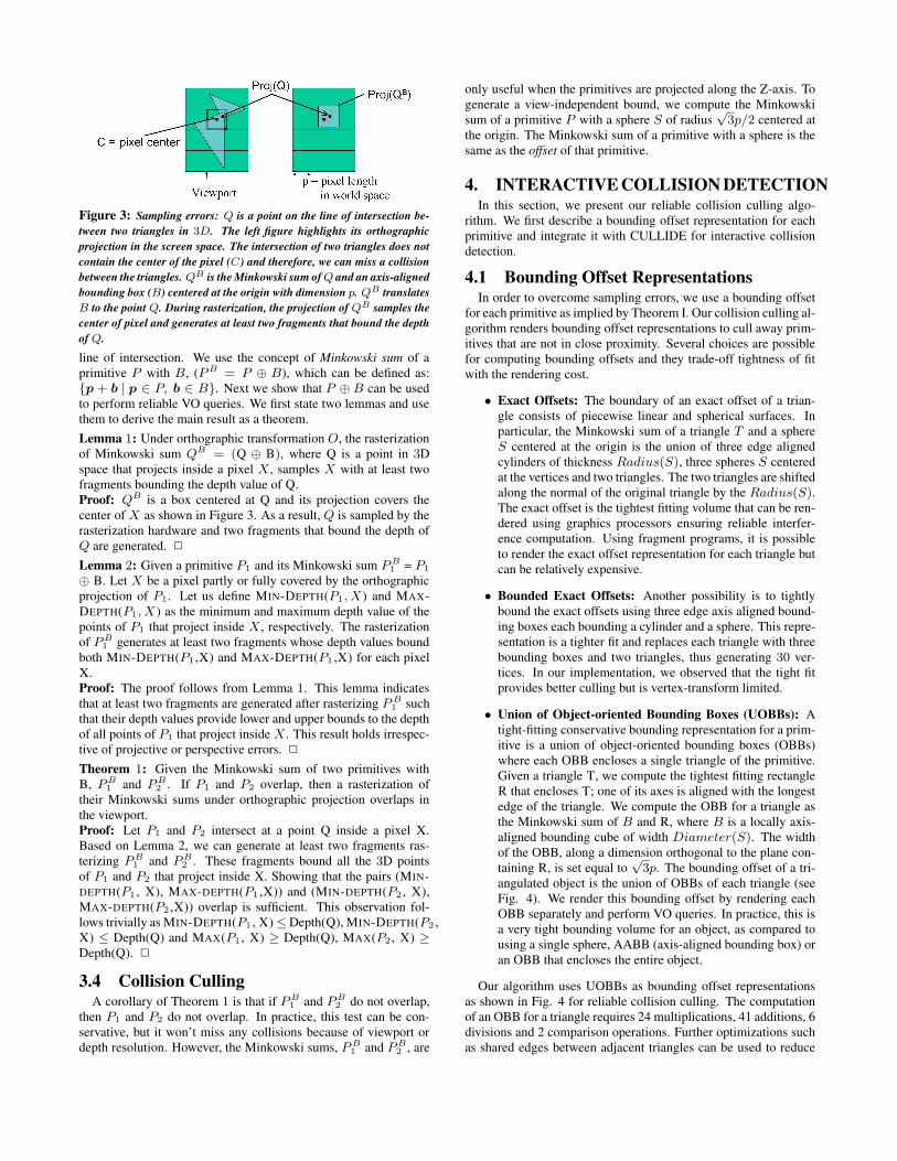
Figure 3: Sampling errors: Q is a point on the line of intersection be-tween two triangles in 3D. The left figure highlights its orthographicprojection in the screen space. The intersection of two triangles does notcontain the center of the pixel (C) and therefore, we can miss a collisionbetween the triangles. QB is the Minkowski sum of Q and an axis-alignedbounding box (B) centered at the origin with dimension p. QB translatesB to the point Q. During rasterization, the projection of QB samples thecenter of pixel and generates at least two fragments that bound the depthof Q.
line of intersection. We use the concept of Minkowski sum of aprimitive P with B, (P B = P ⊕ B), which can be defined as:{p + b | p ∈ P, b ∈ B}. Next we show that P ⊕ B can be usedto perform reliable VO queries. We first state two lemmas and usethem to derive the main result as a theorem.Lemma 1: Under orthographic transformation O, the rasterizationof Minkowski sum QB = (Q ⊕ B), where Q is a point in 3Dspace that projects inside a pixel X , samples X with at least twofragments bounding the depth value of Q.Proof: QB is a box centered at Q and its projection covers thecenter of X as shown in Figure 3. As a result, Q is sampled by therasterization hardware and two fragments that bound the depth ofQ are generated. 2
Lemma 2: Given a primitive P1 and its Minkowski sum P B1 = P1
⊕ B. Let X be a pixel partly or fully covered by the orthographicprojection of P1. Let us define MIN-DEPTH(P1, X ) and MAX-DEPTH(P1, X ) as the minimum and maximum depth value of thepoints of P1 that project inside X , respectively. The rasterizationof P B
1 generates at least two fragments whose depth values boundboth MIN-DEPTH(P1 ,X) and MAX-DEPTH(P1 ,X) for each pixelX.Proof: The proof follows from Lemma 1. This lemma indicatesthat at least two fragments are generated after rasterizing P B
1 suchthat their depth values provide lower and upper bounds to the depthof all points of P1 that project inside X . This result holds irrespec-tive of projective or perspective errors. 2
Theorem 1: Given the Minkowski sum of two primitives withB, P B
1 and P B2 . If P1 and P2 overlap, then a rasterization of
their Minkowski sums under orthographic projection overlaps inthe viewport.Proof: Let P1 and P2 intersect at a point Q inside a pixel X.Based on Lemma 2, we can generate at least two fragments ras-terizing P B
1 and P B2 . These fragments bound all the 3D points
of P1 and P2 that project inside X. Showing that the pairs (MIN-DEPTH(P1 , X), MAX-DEPTH(P1 ,X)) and (MIN-DEPTH(P2 , X),MAX-DEPTH(P2 ,X)) overlap is sufficient. This observation fol-lows trivially as MIN-DEPTH(P1 , X) ≤ Depth(Q), MIN-DEPTH(P2 ,X) ≤ Depth(Q) and MAX(P1 , X) ≥ Depth(Q), MAX(P2 , X) ≥Depth(Q). 2
3.4 Collision CullingA corollary of Theorem 1 is that if P B
1 and P B2 do not overlap,
then P1 and P2 do not overlap. In practice, this test can be con-servative, but it won’t miss any collisions because of viewport ordepth resolution. However, the Minkowski sums, P B
1 and P B2 , are
only useful when the primitives are projected along the Z-axis. Togenerate a view-independent bound, we compute the Minkowskisum of a primitive P with a sphere S of radius
√3p/2 centered at
the origin. The Minkowski sum of a primitive with a sphere is thesame as the offset of that primitive.
4. INTERACTIVE COLLISION DETECTIONIn this section, we present our reliable collision culling algo-
rithm. We first describe a bounding offset representation for eachprimitive and integrate it with CULLIDE for interactive collisiondetection.
4.1 Bounding Offset RepresentationsIn order to overcome sampling errors, we use a bounding offset
for each primitive as implied by Theorem I. Our collision culling al-gorithm renders bounding offset representations to cull away prim-itives that are not in close proximity. Several choices are possiblefor computing bounding offsets and they trade-off tightness of fitwith the rendering cost.
• Exact Offsets: The boundary of an exact offset of a trian-gle consists of piecewise linear and spherical surfaces. Inparticular, the Minkowski sum of a triangle T and a sphereS centered at the origin is the union of three edge alignedcylinders of thickness Radius(S), three spheres S centeredat the vertices and two triangles. The two triangles are shiftedalong the normal of the original triangle by the Radius(S).The exact offset is the tightest fitting volume that can be ren-dered using graphics processors ensuring reliable interfer-ence computation. Using fragment programs, it is possibleto render the exact offset representation for each triangle butcan be relatively expensive.
• Bounded Exact Offsets: Another possibility is to tightlybound the exact offsets using three edge axis aligned bound-ing boxes each bounding a cylinder and a sphere. This repre-sentation is a tighter fit and replaces each triangle with threebounding boxes and two triangles, thus generating 30 ver-tices. In our implementation, we observed that the tight fitprovides better culling but is vertex-transform limited.
• Union of Object-oriented Bounding Boxes (UOBBs): Atight-fitting conservative bounding representation for a prim-itive is a union of object-oriented bounding boxes (OBBs)where each OBB encloses a single triangle of the primitive.Given a triangle T, we compute the tightest fitting rectangleR that encloses T; one of its axes is aligned with the longestedge of the triangle. We compute the OBB for a triangle asthe Minkowski sum of B and R, where B is a locally axis-aligned bounding cube of width Diameter(S). The widthof the OBB, along a dimension orthogonal to the plane con-taining R, is set equal to
√3p. The bounding offset of a tri-
angulated object is the union of OBBs of each triangle (seeFig. 4). We render this bounding offset by rendering eachOBB separately and perform VO queries. In practice, this isa very tight bounding volume for an object, as compared tousing a single sphere, AABB (axis-aligned bounding box) oran OBB that encloses the entire object.
Our algorithm uses UOBBs as bounding offset representationsas shown in Fig. 4 for reliable collision culling. The computationof an OBB for a triangle requires 24 multiplications, 41 additions, 6divisions and 2 comparison operations. Further optimizations suchas shared edges between adjacent triangles can be used to reduce

the number of operations. Alternatively, other tight bounding vol-umes such as triangular prisms could be used. However, they canbe expensive to compute as compared to OBBs and are more con-servative for long, skinny triangles. In particular, computation of atriangular prism involves 48 multiplications, 51 additions, 9 divi-sion operations.
Figure 4: This image shows an object with three triangles and its bound-ing offset representation (UOBB) in wireframe. The UOBB is representedas the union of OBBs of each triangle. In practice, this bounding offsetis a tight fitting bounding volume and used for culling.
4.2 AlgorithmWe have integrated our culling algorithm with CULLIDE [8]
to perform reliable collision detection between objects in a com-plex environment. As described in section 3, CULLIDE uses VOqueries to perform collision culling on GPUs. We extend CUL-LIDE to perform reliable collision culling on GPUs by using reli-able VO queries described above. For each primitive in the PCS,we compute its bounding offset (i.e. union of OBBs) representationand use the bounding offset representations in CULLIDE to test ifthe primitives belong to PCS or not.
Our collision detection algorithm, FAR, proceeds in three steps.First we compute the PCS at the object level. We use sweep-and-prune [6] on the PCS to compute the overlapping pairs at the objectlevel. Next we compute the PCS at the sub-object level and theoverlapping pairs. Finally, we perform exact interference tests be-tween the triangles on the CPU [21].
4.2.1 OptimizationsWe have implemented several optimizations in our algorithm.
Bounding offset representations generate nearly twice the amountof fill in comparison to the original geometric primitives. As theoffset representation for each triangle is closed, we can reduce thefill requirements for our algorithm by a factor of two by using face-culling. In our optimized algorithm, we cull front faces while ren-dering the offset representations with occlusion queries and we cullback faces while rendering the offset representations to the framebuffer. These operations can be performed efficiently using back-face culling on graphics hardware. We also reduce the number ofocclusion queries in the second pass of our algorithm by testingonly those primitives whose offset representations are fully visiblein first pass.The pseudo-code for our optimized algorithm is given below:
• First pass:
1. Clear the depth buffer (use orthographic projection)
2. For each object Pi, i = 1, .., n
– Disable the depth mask and set the depth functionto GL GEQUAL.
– Enable back-face culling to cull front faces.– For each sub-object T i
k in Pi
Render offset representation of T ik using
an occlusion query– Enable the depth mask and set the depth function
to GL LEQUAL.– Enable back-face culling to cull back faces.– For each sub-object T i
k in Pi
Render offset representation of T ik
3. For each object Pi, i = 1, .., n
– For each sub-object T ik in Pi
Test if T ik is not visible with respect to the
depth buffer. If it is not visible, set a tag tonote it as fully visible.
• Second pass:
Same as First pass, except that the two “For eachobject” loops are run with i = n, .., 1 and weperform occlusion queries only if the primitive isfully visible in first pass.
4.3 Localized Distance CullingMany algorithms aim to compute all pairs of objects whose sep-
aration distance is less than a constant distance D. In this case,we modify GPU-based culling algorithms to cull away primitiveswhose separation distance is more than D. Given a distance d,our goal is to prune triangles further than d. We can easily modifythe culling algorithm presented above to perform this query. Wecompute the offset of each primitive by using a sphere of radiusD2
+√
3p
2, rasterize these offsets and prune away a subset of prim-
itives whose separation distance is more than D.
4.4 AccuracyWe perform reliable VO queries by rendering the bounding off-
sets of primitives. Theorem I guarantees that we won’t miss anycollisions due to the viewport resolution or sampling errors. Weperform orthographic projections as opposed to perspective projec-tions. Further, the rasterization of a primitive involves linear in-terpolation along all the dimensions. As a result, the rasterizationof the bounding offsets guarantees that we won’t miss any colli-sion due to depth-buffer precision. If the distance between twoprimitives is less than the depth buffer precision, 1
RES(Z), then VO
query on their offsets will always return them as overlapping. Con-sequently, the accuracy of the culling algorithm is governed by theaccuracy of the hardware used for performing vertex transforma-tions and mapping to the 3D grid. For example, many of the cur-rent GPUs use IEEE 32-bit floating point hardware to perform thesecomputations.
5. IMPLEMENTATIONWe have implemented FAR on a Dell precision workstation with
a 2.8 GHz Xeon processor, 1 GB of main memory, and a NVIDIAGeForce FX 5950 Ultra graphics card. We use a viewport resolu-tion of 1400 × 1400 to perform all the computations. We improvethe rendering throughput by using vertex arrays and useGL NV occlusion query to perform the visibility queries.
5.1 BenchmarksWe have tested our algorithm on three complex scenes and have
compared its culling performance and accuracy with some prior

Figure 5: Breaking object scene: In this simulation, the bunny model falls on the dragon which eventually breaks into hundreds of pieces. FAR computescollisions among the new pieces of small objects introduced into the environment and takes 30 to 60 msec per frame.
approaches.
Dynamically generated breaking objects: The scene consists of adragon model initially with 112K polygons, and a bunny with 35Kpolygons, as shown in Fig. 5. In this simulation, the bunny fallson the dragon, causing the dragon to break into many pieces overthe course of the simulation. Each piece is treated as a separateobject for collision detection. Eventually hundreds of new objectsare introduced into the environment. We perform collision cullingto compute which object pairs are in close proximity. It takes about35 msec towards the beginning of the simulation, and about 50msec at the end when the number of objects in the scene is muchhigher.
Figure 6: Relative culling performance on breaking objects scene:This graph highlights the improved culling performance of our algo-rithm as compared to a CPU-based culling algorithm (I-COLLIDE) thatuses AABBs (axis-aligned bounding boxes) to cull away non-overlappingpairs. FAR reports 6.9 times fewer pairs over the entire simulation.
We compared the culling performance of our GPU-based reliableculling algorithm with an implementation of the sweep-and-prunealgorithm available in I-COLLIDE [6]. The sweep-and-prune al-gorithm computes an axis-aligned bounding box (AABB) for eachobject in the scene and checks all the AABBs for pairwise over-laps. Fig. 6 shows the comparison between the culling efficiency ofAABB-based algorithm vs. FAR. Overall, FAR returns 6.9 timesfewer overlapping pairs. This reduction occurs mainly becauseFAR uses much tighter bounding volumes, i.e. the union of OBBsfor an object as compared to an AABB and is able to cull awaymore primitive pairs.
Interference computation between complex models: In this scene,we compute all the overlapping triangles pairs between a 68K trian-gles bunny that is moving with respect to another bunny, also with68K triangles. The bunnies are deeply penetrating and the inter-
section boundary consists of 2, 000 − 4, 000 triangle pairs. In thiscase, the accuracy of FAR equals that of a CPU-based algorithmusing 32-bit IEEE floating point arithmetic. In contrast, CULLIDEmisses a number of overlapping pairs while using a viewport reso-lution of 1, 400 × 1, 400. The intersection sets computed by FARand CULLIDE are shown in Fig. 7.
Multiple objects with non-rigid motion: This scene consists ofa non-rigid simulation in which leaves fall from the tree, as shownin Fig. 1. We compute collisions among the leaves of the tree andamong the leaves and branches of the tree. Each leaf is representedusing 156 triangles and the complete environment consists of 40Ktriangles. The average collision detection time is 35 msec per timestep.
5.2 Comparison with Other ApproachesWe have compared our algorithm with a CPU-based implemen-
tation SOLID [30] on the environment with dynamically generatedbreaking objects. SOLID is a publicly available library that usespre-computed AABB-trees for collision culling. As the objects inour scene are dynamically generated and the topology of existingobjects (eg. dragon) change, we need to dynamically compute thehierarchies. Moreover, as the hierarchies are recomputed, there isan additional overhead of allocating and deallocating memory inSOLID. Ignoring the overhead due to memory, we observed that thepre-computation of data-structures for SOLID require 100 − 176ms per frame. These timings do not include the pruning time. Onthe contrary, we are able to compute all collisions within 50ms (in-cluding UOBB computation time and pruning time).
We have also compared our algorithm with an optimized GPUimplementation of CULLIDE. Our implementation runs nearly 3times slower due to the overhead of rasterizing bounding boxes in-stead of triangles. However, as shown in Fig. 7, CULLIDE missesseveral interferences and may lead to inaccurate simulations.
6. ANALYSIS AND LIMITATIONSThree key issues exist related to the performance of conserva-
tive collision culling algorithms: efficiency, level of culling, andprecision.
Efficiency: Three factors govern the running time of our algorithm:bounding offset computation, rendering the bounding offsets andocclusion queries. The cost of computing the OBBs for each prim-itive is very small. The cost of rendering the OBBs on the GPUsis mainly governed by the transformations. In our current imple-mentation, we have achieved rendering rates of 40M triangles persecond. Finally, our algorithm uses occlusion queries to perform

(a) Interference computation on two bunnies (b) Intersection curve com-puted by CULLIDE
(c) Intersection curve com-puted by FAR
Figure 7: Reliable interference computation: This image highlights the intersection set between two bunnies, each with 68K triangles (shown in Fig7(a)). Fig. 7(c) shows the output of FAR and Fig. 7(b) highlights the output of CULLIDE running at a resolution of 1400 × 1400. CULLIDE missesmany collisions due to the viewport resolution and sampling errors.
VO queries. These queries can be fill bound for large objects. Thecurrent implementation of these queries is not optimized, yet weare able to perform 1.2 million queries per second. FAR is ableto compute all the collisions between models composed of tens ofthousands of primitives at interactive rates. In more complex envi-ronments (e.g. with millions of triangles), rendering and occlusionqueries can become a bottleneck. However, given the growth rate ofGPU performance (at a rate faster than Moore’s law) and increas-ing bus bandwidth based on PCI-X, we expect that our algorithmcan handle more complex models in the near future.
Culling: The effectiveness of most collision detection algorithmsdepends on how efficiently they can cull away the primitives thatare not in close proximity. FAR uses union of OBBs as the un-derlying bounding volume and is less conservative as compared toCPU based algorithms that use AABBs or spheres to bound theprimitives (see Fig. 6).
Precision: Our culling algorithm is conservative and its precisionis governed by that of the VO queries. The accuracy of the cullingalgorithm is equivalent to that of the floating point hardware (e.g.32-bit IEEE floating point) inside the GPUs used to perform trans-formations and rasterization. The precision is not governed byviewport resolution or depth-buffer precision.
7. CONCLUSIONS AND FUTURE WORKIn this paper, we have presented a reliable GPU-based collision
culling algorithm. We use bounding offsets of the primitives toperform visibility-based 2.5D queries and cull away primitives thatare not in close proximity. Our new algorithm overcomes a ma-jor limitation of earlier GPU-based collision detection algorithmsand is able to perform reliable interference queries. Furthermore,the culling efficiency of our algorithm is higher as compared to
prior CPU-based algorithms that use AABBs or spheres for colli-sion culling. Moreover, the culling efficiency and performance canbe significantly enhanced by using Quick-CULLIDE [24]. We havedemonstrated its performance in complex scenarios where objectsundergo rigid and non-rigid motion.
Desirable Hardware Features: We propose a simple architecturefor the graphics pipeline to accelerate the performance of our algo-rithm. The modified architecture requires the following character-istics:
• Precision: In order to obtain floating point precision, thegraphics pipeline should support floating point depth buffers.However, it is important to note that the viewport resolutionis mainly responsible for the sampling errors than the depthbuffer precision. Therefore, floating point depth buffers alonecannot solve the sampling problem.
• Rasterization Rules: We set a state in which the followingrasterization rules are used. These rules are used to overcomethe viewport resolution problems.
– A fragment is generated for each pixel that a triangletouches.
– For each pixel, depth is computed at all the four cornersamples of the rectangular pixel. A depth set functionis applied onto the four depth samples and one of thefour values is output as the depth of current fragment.The depth set function could either be {max, min} andis specified as a state before rasterizing a primitive. Thefunction max computes the maximum value of the fourdepth samples and min computes the minimum value ofthe four depth samples.
The above rules are sufficient to design an algorithm ensuringfloating point precision for interference computations. In the pseudo-
code described in section 4.2.1, while rendering a primitive to theframe buffer, we set the depth set function to min along with thedepth function GL LEQUAL. This operation ensures that for eachpixel touched by a primitive, we compute the minimum depth ofall points of the primitive that project onto the pixel. While testingthe fully visible status of a primitive, the depth set function is setto max. This operation ensures that we test if the maximum depthof all points of a primitive that project onto the pixel is fully visibleor not. It is easy to see that these two operations can be used toconservatively test if a primitive interferes with another primitiveor not.
Most graphics hardware implementations involve tile-based ras-terization [1, 15, 20, 22]. All the pixels covered by a primitive andwithin a tiled region, say a region consisting of 4 × 4 pixels arecomputed before moving to the next tile. As adjacent pixels sharecommon sample points, it is possible to design a simple architecturecomputing the depth at a sample point, say left corner of a pixel,and depth values at the samples covering the top and right cornersof a tile. A simple hardware can be used to compute the max or minvalues of these fragments in a tile and output the sample depths.
The proposed implementation requires the computation of moresamples than the actual number of samples in normal rasterizationpipeline. However, the overhead of this computation can be mini-mized by using additional hardware.
In terms of future work, we would like to develop reliable and ac-curate GPU-based geometric algorithms for other proximity queriessuch as penetration and distance computation, as well as visibilityand shadow computations.
AcknowledgementsOur work was supported in part by ARO Contracts DAAD19-02-1-0390 and W911NF-04-1-0088, NSF awards 0400134 and 0118743,ONR Contracts N00014-01-1-0067 and N00014-01-1-0496, DARPAContract N61339-04-C-0043 and Intel. We would like to thankNVIDIA corporation for the hardware and driver support. We arethankful to Kelly Ward for helping us with video editing and mem-bers of UNC GAMMA group for useful discussions.
8. REFERENCES[1] Tomas Akenine-Moller and Jacob Strom. Graphics for the masses: a
hardware rasterization architecture for mobile phones. ACM Trans.Graph., 22(3):801–808, 2003.
[2] G. Baciu and S.K. Wong. Image-based techniques in a hybridcollision detector. IEEE Trans. on Visualization and ComputerGraphics, 2002.
[3] G. Baciu, S.K. Wong, and H. Sun. Recode: An image-based collisiondetection algorithm. Proc. of Pacific Graphics, pages 497–512, 1998.
[4] G. Barequet, B. Chazelle, L. Guibas, J. Mitchell, and A. Tal. Boxtree:A hierarchical representation of surfaces in 3D. In Proc. ofEurographics’96, 1996.
[5] N. Beckmann, H. Kriegel, R. Schneider, and B. Seeger. The r*-tree:An efficient and robust access method for points and rectangles.Proc. SIGMOD Conf. on Management of Data, pages 322–331, 1990.
[6] J. Cohen, M. Lin, D. Manocha, and M. Ponamgi. I-COLLIDE: Aninteractive and exact collision detection system for large-scaleenvironments. In Proc. of ACM Interactive 3D Graphics Conference,pages 189–196, 1995.
[7] S. Gottschalk, M. Lin, and D. Manocha. OBB-Tree: A hierarchicalstructure for rapid interference detection. Proc. of ACM Siggraph’96,pages 171–180, 1996.
[8] N. Govindaraju, S. Redon, M. Lin, and D. Manocha. CULLIDE:Interactive collision detection between complex models in largeenvironments using graphics hardware. Proc. of ACMSIGGRAPH/Eurographics Workshop on Graphics Hardware, pages25–32, 2003.
[9] Alexander Gress and Gabriel Zachmann. Object-space interferencedetection on programmable graphics hardware. In SIAM Conf. onGeometric Design and Computing, Seattle, Washington,November13–17 2003.
[10] B. Heidelberger, M. Teschner, and M. Gross. Real-time volumeticintersections of deforming objects. Proc. of Vision, Modeling andVisualization, 2003.
[11] M. Held, J. Klosowski, and J. S. B. Mitchell. Real-time collisiondetection for motion simulation within complex environments. InProc. ACM SIGGRAPH’96 Visual Proceedings, page 151, 1996.
[12] K. Hoff, A. Zaferakis, M. Lin, and D. Manocha. Fast and simple 2dgeometric proximity queries using graphics hardware. Proc. of ACMSymposium on Interactive 3D Graphics, pages 145–148, 2001.
[13] P. M. Hubbard. Interactive collision detection. In Proceedings ofIEEE Symposium on Research Frontiers in Virtual Reality, October1993.
[14] P. Jimenez, F. Thomas, and C. Torras. 3d collision detection: Asurvey. Computers and Graphics, 25(2):269–285, 2001.
[15] B. Kelleher. Pixelvision architecture. Technical Report 1998-013,Digital Systems Research Center, 1998.
[16] Y. J. Kim, M. A. Otaduy, M. C. Lin, and D. Manocha. Fastpenetration depth computation for physically-based animation. Proc.of ACM Symposium on Computer Animation, 2002.
[17] J. Klosowski, M. Held, J.S.B. Mitchell, H. Sowizral, and K. Zikan.Efficient collision detection using bounding volume hierarchies ofk-dops. IEEE Trans. on Visualization and Computer Graphics,4(1):21–37, 1998.
[18] D. Knott and D. Pai. Cinder: Collision and interference detection inreal-time using graphics hardware. Proc. of Graphics Interface,pages 73–80, 2003.
[19] M. Lin and S. Gottschalk. Collision detection between geometricmodels: A survey. Proc. of IMA Conference on Mathematics ofSurfaces, 1998.
[20] Joel McCormack and Robert McNamara. Tiled polygon traversalusing half-plane edge functions. In Proceedings of the ACMSIGGRAPH/EUROGRAPHICS workshop on Graphics hardware,pages 15–21. ACM Press, 2000.
[21] T. Moller. A fast triangle-triangle intersection test. Journal ofGraphics Tools, 2(2), 1997.
[22] S. Morein. ATI Radeon HyperZ technology. In ACMSIGGRAPH/EUROGRAPHICS workshop on Graphics hardware,Hot3D Proceedings, 2000.
[23] K. Myszkowski, O. G. Okunev, and T. L. Kunii. Fast collisiondetection between complex solids using rasterizing graphicshardware. The Visual Computer, 11(9):497–512, 1995.
[24] M. Lin N. Govindaraju and D. Manocha. Quick-cullide: Fast inter-and intra-object collision culling using graphics hardware. Technicalreport, University of North Carolina at Chapel Hill, July 2004.
[25] M. Ponamgi, D. Manocha, and M. Lin. Incremental algorithms forcollision detection between solid models. IEEE Transactions onVisualization and Computer Graphics, 3(1):51–67, 1997.
[26] S. Quinlan. Efficient distance computation between non-convexobjects. In Proceedings of International Conference on Robotics andAutomation, pages 3324–3329, 1994.
[27] Ramesh Raskar and Michael Cohen. Image precision silhouetteedges. In Proceedings of the 1999 symposium on Interactive 3Dgraphics, pages 135–140. ACM Press, 1999.
[28] J. Rossignac, A. Megahed, and B.D. Schneider. Interactive inspectionof solids: cross-sections and interferences. In Proceedings of ACMSiggraph, pages 353–60, 1992.
[29] M. Shinya and M. C. Forgue. Interference detection throughrasterization. The Journal of Visualization and Computer Animation,2(4):131–134, 1991.
[30] Freesolid: Software library for interference detection.http://www.win.tue.nl/ gino/solid/.
[31] T. Vassilev, B. Spanlang, and Y. Chrysanthou. Fast cloth animationon walking avatars. Computer Graphics Forum (Proc. ofEurographics’01), 20(3):260–267, 2001.

![Masked Depth Culling for Graphics Hardwarefileadmin.cs.lth.se/graphics/research/papers/2015/ZMM/zmm.pdf · occlusion culling has been presented by Aila and Miettinen [2004], and in](https://static.fdocuments.in/doc/165x107/5f5cee072281505ece252c20/masked-depth-culling-for-graphics-occlusion-culling-has-been-presented-by-aila-and.jpg)