FARO ScanArm Plugin - s3.amazonaws.com · If this item does not already appear on the Plu- ......
40
Geomagic, Inc. FARO ScanArm Plugin Document Version G April 18, 2007 page 1 FARO ScanArm Plugin For compatibility with Geomagic products, see Release Notes for Geomagic FARO Plugin Document version G. Copyright © 2007, Geomagic, Inc. ______________________________________________________ Plugins > FARO is the interface in Geomagic Studio and Geomagic Qualify to a FARO ScanArm. (This menu item in Geomagic products is an optional, separately licensed feature. If this item does not already appear on the Plu- gins menu, download the software from http://www.geomagic.com/support/ plugins, install it according to instructions on the web site, and re-start this procedure.) The purpose of this (or any) scanner plugin is to eliminate the need to import scan data into Geomagic Studio or Qualify. With the plugin, scanned data exists in the application’s Model Manager immediately after the data capture process. Table of Contents Activating the Plugin 2 Controls on the Arm 2 Controls and Indicators 3 Hardware Alignment button 3 Hard Probe Features and Datums button 4 Probe Capture button 6 Laser Capture button 8 Laser Compare button 11 OK button 14 Cancel button 14 Merge button 14 Referencing the Encoders 15 Calibrating the Hard and Laser Probes 15 3-2-1 Alignment 20 Feature/Datum Info Window 24 Datum and Feature Creation 26 Move Device 30 Detailed Examples 38 Aligning Test and Reference Parts with Geomagic Qualify 38 Example of Laser Scanning 39 Example of Laser Compare 40
Transcript of FARO ScanArm Plugin - s3.amazonaws.com · If this item does not already appear on the Plu- ......

Geomagic, Inc. FARO ScanArm Plugin
FARO ScanArm PluginFor compatibility with Geomagic products, see Release Notes for Geomagic FARO Plugin
Document version G. Copyright © 2007, Geomagic, Inc.
______________________________________________________
Plugins > FARO is the interface in Geomagic Studio and Geomagic Qualify to a FARO ScanArm. (This menu item in Geomagic products is an optional, separately licensed feature. If this item does not already appear on the Plu-gins menu, download the software from http://www.geomagic.com/support/plugins, install it according to instructions on the web site, and re-start this procedure.)
The purpose of this (or any) scanner plugin is to eliminate the need to import scan data into Geomagic Studio or Qualify. With the plugin, scanned data exists in the application’s Model Manager immediately after the data capture process.
Table of Contents
Activating the Plugin 2
Controls on the Arm 2
Controls and Indicators 3Hardware Alignment button 3Hard Probe Features and Datums button 4Probe Capture button 6Laser Capture button 8Laser Compare button 11OK button 14Cancel button 14Merge button 14
Referencing the Encoders 15Calibrating the Hard and Laser Probes 153-2-1 Alignment 20Feature/Datum Info Window 24Datum and Feature Creation 26Move Device 30Detailed Examples 38
Aligning Test and Reference Parts with Geomagic Qualify 38Example of Laser Scanning 39Example of Laser Compare 40
Document Version G April 18, 2007 page 1

Geomagic, Inc. FARO ScanArm Plugin
Activating the PluginTurn on the FARO scanner before selecting Plugins > FARO
Controls on the ArmAfter you press the Start Capture button in the dialog, the arm buttons are enabled and the scanner is in the Paused state.
• During Laser Scanning:• Red Buttons (identical function; known as the Stop buttons) - Stops
and returns control to the plugin dialog.• Green Buttons (known as the Pause/Unpause buttons) - Press once
to activate the laser and scan the physical object. Press again to pause the scanner. Each cycle of Unpause/Pause generates a uniquely num-bered “Scan N” object in the Geomagic model manager. When a suffi-cient number of Scans are complete, press the Red button to stop scanning and return control to the plugin dialog.
• During Hard Probing:• Red Buttons (identical function; known as the Offset/Stop buttons) -
stops an operation or defines an offset.• Green Buttons (known as the Collect buttons) - collects a point.
page 2 April 18, 2007 Document Version G

Geomagic, Inc. FARO ScanArm Plugin
Controls and IndicatorsThis section details the controls and indicators on the user interface of the FARO plugin.
• Hardware Alignment icon button - Alignment is the synchro-
nization of the coordinate system of a reference object with the coordi-nate system of the scanner and test object, such that the coordinates of incoming data points can be correctly compared to points on the refer-ence object. This button activates controls and indicators for the align-ment process. Every scan must be performed with respect to a known spatial orientation (also called a “coordinate system”, also incorrectly called an “alignment”). The spatial orientation remains in effect on subse-quent scans and the next time Geomagic Studio or Qualify is started.• Display Units - specifies the units of measure on the object that will
be scanned, such as inches or millimeters.• Probe Controls group - contains hardware-specific controls.
• Probe Options button - presents a popup window in which
you specify and calibrate the physical probe that is attached to the FARO arm. In the Current Probe dropdown, identify the currently installed hard probe (such as 3mm Ball Probe). Optionally, perform calibration of that probe. Click OK.
Define a coordinate system (an orientation) by one of the following meth-ods.
• Load Transform button - allows the user to select a .tfm or .xal
file that defines a spatial orientation.
• Use Arm CSYS button - sets the spatial orientation (also called
Coordinate SYStem) to the arm default, where the arm base is the ori-gin.
• 3-2-1 Alignment button - Allows the user to establish spatial
orientation by defining the position of the X, Y, and Z planes. See 3-2-1 Alignment on page 20.
Document Version G April 18, 2007 page 3
Geomagic, Inc. FARO ScanArm Plugin
• “Move Device” Wizard is a specialized procedure for aligning
the multiple scans of an object that is larger than the reach of the arm. It involves the hard-probing of reference points, moving the object or the arm itself, and hard-probing of the same reference points to re-establish bearings. This section presents two buttons that are the entry point to the “Move Device” feature. See Move Device on page 30.
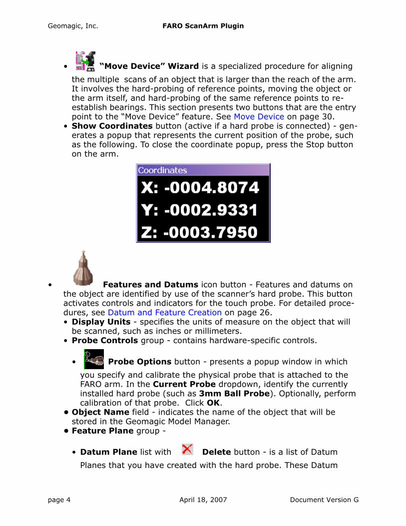
• Show Coordinates button (active if a hard probe is connected) - gen-erates a popup that represents the current position of the probe, such as the following. To close the coordinate popup, press the Stop button on the arm.
• Features and Datums icon button - Features and datums on the object are identified by use of the scanner’s hard probe. This button activates controls and indicators for the touch probe. For detailed proce-dures, see Datum and Feature Creation on page 26.• Display Units - specifies the units of measure on the object that will
be scanned, such as inches or millimeters.• Probe Controls group - contains hardware-specific controls.
• Probe Options button - presents a popup window in which
you specify and calibrate the physical probe that is attached to the FARO arm. In the Current Probe dropdown, identify the currently installed hard probe (such as 3mm Ball Probe). Optionally, perform calibration of that probe. Click OK.
• Object Name field - indicates the name of the object that will be stored in the Geomagic Model Manager.
• Feature Plane group -
• Datum Plane list with Delete button - is a list of Datum
Planes that you have created with the hard probe. These Datum
page 4 April 18, 2007 Document Version G
Geomagic, Inc. FARO ScanArm Plugin
Planes can be referenced during the creation of planar Features (holes, slots, rectangles, and lines). “Define Plane” is a special case that requires the user to define a plane during Feature creation rather than by referencing one from this list.
• Datum/Feature Type group - specifies the kind of datum or feature that will be defined by use of the hard probe. A datum or feature can be defined even if no scan data exists yet. If no scan data yet exists, an “empty” point object called Datums/Features is created in the Model Manager and the new datum and feature sub-objects are stored under it. The datum types are:
plane, axis, point, and point target.
The feature types are:
hole, slot, rectangle, and line.
For complete definitions, see the online help in the Geomagic product at Tools > Datums > Create Datums.
• Input Method group - (applicable with some of the Datum types) specifies the method by which you will use the hard probe to define the datum. A datum can be defined even if no scan data exists yet. If no scan data yet exists, an “empty” point object called Datums/Features is created in the Model Manager and the new datum and feature sub-objects are stored under it. The Input Methods are:
• Cylinder (for the axis datum) - the user is instructed to click
six or more points on the surface of the cylinder
• Cone (for the axis datum) - the user is instructed to click six
or more points on the surface of the cone
• Surface Point (for the point datum and point target datum) -
the user is instructed to probe three points to define a plane, then one point on the surface of that plane.
• Best Fit Centroid (for the point datum and point target
datum) - the user is instructed to select three or more points to define a plane. The defined point is at the best-fit center of this col-lection.
Document Version G April 18, 2007 page 5

Geomagic, Inc. FARO ScanArm Plugin
• Sphere (for the point datum) - the user is instructed to select
four or more points on the sphere surface. The defined point is at the center of this sphere.
• Single Point (for the point datum) - the user is instructed to
probe one point. The defined point is at the center of the probe.• Point Size decimal field - controls the size of points that appear in the
Viewing Area during the probing of a feature or datum.• Show/Hide Information Window button - toggles the display of the
Feature/Datum Information Window (the feedback window that pops up when a Feature or Datum is being collected). See Feature/Datum Info Window on page 24.
• Save Compensated Points checkbox - causes probed points to be saved to the Model Manager with the new feature or datum. The probed points are saved to the point object (named “Features/Datums”) of which the feature or datum is a member.
• Automatic Resize checkbox - causes automatic scaling or re-orienta-tion of objects so that all collected points remain within bounds of the Viewing Area.
• Show Instructions checkbox - specifies whether the user interface presents instructions on how to define the Datum or Feature given the Datum/Feature Type and the Method Input that is chosen.• Instructions (if requested by the Show Instructions checkbox) -
presents a sentence explaining how to define the datum or feature given the Datum/Feature Type and the Method Input that is chosen.
If you are defining a Feature (hole, slot, rectangle or line), and if a specific Datum Plane name is highlighted in the Datum Plane List above, the highlighted plane will serve as the Feature’s plane and the instructions will describe how to complete the process in minimal number of steps. If “Define Plane” is highlighted in the Datum Plane list above, the instructions will also describe how to probe the Fea-ture’s plane.
• Probe Capture icon button - Probe Capture is a data collection
method that utilizes the hard probe only. Even after laser scanning, it is often useful to hard-probe sharp edges of a part.• Disconnect Arm button - deactivates the arm so you can make
changes with the Probe Profile or Probe Special Functions buttons. (To reactivate the arm, restart the plugin.)
page 6 April 18, 2007 Document Version G
Geomagic, Inc. FARO ScanArm Plugin
• Display Units - specifies the units of measure that will display in the Viewing Area, such as inches or millimeters; not the same as the units that will be stored in the data file.
• Probe Controls group - configures the hard probe.
• Probe Options button - presents a popup window in which
you specify and calibrate the physical probe that is attached to the FARO arm. In the Current Probe dropdown, identify the currently installed hard probe (such as 3mm Ball Probe). Optionally, perform calibration of that probe. Click OK.
• Probe Modes group - specifies the technique by which multiple data points are collected.
• Single Point icon button - one point is collected per press of
the button.
• Time icon button - points are collected continuously at a reg-
ular time interval (specified in the Interval decimal field).
• Distance icon button - a point is collected every time the
probe has traveled a distance from the previous point (specified in the Interval decimal field and Units field).
• Object Name field - indicates the name of the object that will be stored in the Geomagic Model Manager. Reset sets the name to “Scan 001”.
• Probing Options group - • Automatic Resize checkbox - specifies that the real-time graphical
Viewing Area will automatically zoom to accomodate the incoming data.
• Virtual Camera checkbox - causes the Viewing Area to continuously reorient itself to simulate the view from an imaginary camera on the arm.
• Start Capture icon button - begins the data capture process
by passing control to the arm.• Data Options group -
• Merge Scan Passes checkbox - specifies whether to merge the data from all scan passes into a single object in the Model Manager (or to store every scan pass as a separate object).
Document Version G April 18, 2007 page 7
Geomagic, Inc. FARO ScanArm Plugin
• Sampling checkbox - specifies whether to reduce the density of points on each probed object. Sampling occurs at the end of each probe pass.
• Spacing decimal field - (in conjunction with Sampling) specifies the target distance between points.
• Laser Capture icon button - Laser Capture is the process of col-
lecting data points from a physical part. This button activates controls and indicators for the laser scanner.Definitions: Ordered data is a point cloud of consistent density whose points exist in orderly rows and/or columns. Unordered data (also called Raw data) is a point cloud of variable density whose points exist at any location in space.• Display Units - specifies the units of measure on the object that will
be scanned, such as inches or millimeters.• Scanner Controls group - adjusts laser scanner settings.
• Calibrate Scanner: Click this if calibration is required for the
laser probe. Some procedures may also require calibration of the hard probe..
• Scanner Options: Brings up a device-specific dialog that
allows specific adjustment of the laser scanner operations.• Object Options group - controls the organization of new scans in the
Geomagic Model Manager.• Store Data In dropdown - The set of choices depends on the Data
Format below.• New Group (selectable when Data Format is Raw Data Only,
Ordered Data Only, or Ordered and Raw Data) - A new group (named Group N) will be created in the Model Manager and the data will be stored therein (in an object named Scan NNN).
• New Object (selectable when Data Format is Raw Data Only) - A new object named Scan NNN will be created in the Model Manager.
• Scan NNN (selectable when Data Format is Raw Data Only) - Data will be added to the existing object named Scan NNN.
• Group N (selectable when Data Format is Ordered Data Only or Ordered and Raw Data) - Data will be added to the existing group named Group N, in a new object named Scan NNN.
• Name field and Reset button - indicates the name of the scan object that will be stored in the Geomagic Model Manager. Names are of the
page 8 April 18, 2007 Document Version G
Geomagic, Inc. FARO ScanArm Plugin
form Scan 001, Scan 002, Scan 003, .... Reset restores the numeric part to 001.
• Scanning Options - control the operation of the scanner and the dis-play of data.• Automatic Resize checkbox - specifies that the real-time graphical
Viewing Area will automatically zoom to accomodate the incoming scan data.
• Virtual Camera checkbox - activates the Virtual Camera functional-ity of the laser scanner.
• Highlight Scan Pass checkbox - activates scan pass hi-lighting. When selected, the incoming scan data will appear red. Otherwise the incoming scan data will match the light green of previously created scan passes.
• Start Capture icon button - begins the data capture process
by passing control to the scanning device.• Data Options group - controls the storage of data in the Geomagic
Model Manager.• Data Format dropdown - specifies the kind of data that will be
stored in the Geomagic Model Manager. (This choice affects the Store Data In dropdown above.)• Ordered Data Only - Data will be stored as ordered data.• Raw Data Only - Data will be stored as unordered (raw) data.• Ordered and Raw Data - Data will be stored as Ordered data and
as Unordered (raw) data in two separate objects.• Enable Clip Plane checkbox - activates the Clip Plane group of
controls (which allows a spurious plane such as a tabletop to be elim-inated from a scan automatically). When enabled, the Advanced Options group, below, contains addtional controls in a Clip Plane group.
• Advanced Options checkbox - actives the display of the controls and indicators below.• Remove Overlap checkbox - specifies that an entire scan line be
rejected if it is mathematically “too close” to the previous scan line. This setting prevents an over-abundance of scan data.
• Remove Outliers checkbox and Spacing decimal field - specifies that points be rejected if they are more than Spacing distance from any other.
• Reduce Noise checkbox and Noise Level slider - performs a degree of smoothing on the surface that is suggested by the cap-tured points.
• Ordered Data Options group - affects data that is stored in the Model Manager as Ordered Data.• Spacing decimal field - the exact spacing of the grid-like struc-
ture of the ordered data.
Document Version G April 18, 2007 page 9

Geomagic, Inc. FARO ScanArm Plugin
• Max. Edge Length decimal field - specifies the maximum length of any side of any square cell. Gaps in the data that are wider than this value are considered to be holes in the object.
• Max. View Deviation decimal field - specifies the change in the scanner angle that causes one scan object to terminate and another to be started automatically. All points in an ordered data object must be visible from a single point of view, so this field controls the automatic breakdown of a “complex” scan into multiple single-view scans.
• Filter Angle decimal field (0.0 to 90.0 degrees) - offers the ability to ignore points collected by the scanner beyond the specified angle. This can result in cleaner data. This operation, like smoothing, is per-scanline.
• Raw Data Options group - affects all incoming data, even if it will be stored in the Model Manager as Ordered data.• Shade Points checkbox - specifies whether to apply shading to
the unordered data so that it can be better visualized in the Viewing Area (possibly at the expense of performance).
• Sample Points checkbox with Spacing decimal field and Max. Error decimal field - specifies whether to reduce the density of points on each scan line. Sampling occurs at the end of each scan pass. Spacing is the target distance between points. Sam-pling tends to “smooth” (reduce the precision of) a scan, so the Max. Error parameter controls the maximum distance that a point is allowed to move as the result of such smoothing. Point reduction is performed to achieve the requested Spacing along each scan line, except at specific locations on the line where the distance between points is allowed to be smaller in order to accomodate the Max. Error.
• Clip Plane group - (only when Enable Clip Plane checkbox is checked) specifies a plane that must be eliminated from a scan automatically, such as a tabletop.
• Plane dropdown (“Last Used” plus the names of every plane listed in the Model Manager) specifies a plane that will be elim-inated from a future scan. All data above the plane (in the plane’s normal direction) will be considered good data. “Last Used” is the most recently used clip plane, from this or a pre-vious session of the application or plugin.
• Display Plane checkbox - specifies whether to display the clip plane during the scan.
• Flip Normal checkbox - reverses the normal direction of the clip plane.
• Offset decimal field - specifies a distance in the normal direc-tion by which to shift the clip plane. If an object is resting on an uneven tabletop, and a plane P representing this tabletop is therefore created 2 millimeters higher than intended, and the
page 10 April 18, 2007 Document Version G
Geomagic, Inc. FARO ScanArm Plugin
normal direction of Plane P us “up”, and plane P is designated as a clip plane, the scanned object would be missing 2 milli-meters of data near its bottom. By setting this Offset field to negative 2 mm, the clip plane is lowered. Everything above the tabletop will be included in the scan and every point on and below the clip plane is eliminated.
• Add Scanned Plane button - When pressed, control is passed to the scanning device. The user is expected to scan the table-top only. When capture is complete, a plane is derived from the captured data and added to the Model Manager as a sub-object called Plane N in a Datums folder under a separate unordered object called Scanned Planes. Next, the plane rep-resenting the tabletop may be selected in the Plane dropdown above, causing the tabletop to be excluded from future scans.
• Set to Defaults button - sets all Advanced Options to their default values.
• Laser Compare icon button (visible in Geomagic Qualify, not
Geomagic Studio) - Laser Compare (previously called Real-Time 3D Comparison) is a scanning method during which the deviations between scanned points and a reference object are graphically illustrated in real time. This button activates the laser scanner in a mode that performs Laser Comparison of the scanned object to a reference object.• Scanner Controls group - is identical to the “Scanner Controls
group” under the Laser Capture icon button, detailed on page 8.• Initialize button - initializes the comparison process by creating an
empty Result object in the Geomagic Model Manager.• Scanning Options - control the operation of the scanner and the dis-
play of data.• Virtual Camera checkbox - activates the Virtual Camera functional-
ity of the laser scanner.
• Start Compare icon button - begins the data comparison pro-
cess by passing control to the scanning device.• Objects group -
• Reference - indicates the name of the object in the Geomagic Model Manager that is designated as the Reference object.
• Scan - indicates that the test object is the “New Object” that is being scanned.
• Max. Deviation field - indicates the greatest difference between corre-sponding reference and test points to allow in the test data. Points beyond this deviation are not included in the test data set.
Document Version G April 18, 2007 page 11
Geomagic, Inc. FARO ScanArm Plugin
• Color Averaging slider (five settings from Low to High) - affects the degree to which colors are blended and averaged across the entire sur-face, like an airbrush that hides small blemishes.
• Display group - controls various aspects of the graphical display:• Test Object checkbox - specifies whether to display the raw test
data points during the data capture process.• Color radio buttons - specifies the one attribute that will be colored in
the Viewing Area:• Color Reference - color will appear on the reference object.• Color Test Points - color will appear on test points.• Color Deviations - color will appear on whisker lines that extend
between test points and the reference object.• Edit Spectrum checkbox - allows modification of the color coding
scheme of the deviation map in the Viewing Area.• Edit Texture Resolution checkbox - specifies whether to display the
following controls:• Texture Resolution group - For the purpose of generating color
on the reference object, a grid with uniform cell sizes is placed across its surface. Each square cell is called a texel. Scan points are projected onto the texels. When 0 scan points correspond to a texel, the texel is gray, indicating that the test object has insuffi-cient data in that region for color to be rendered on the reference object. When one point corresponds to a texel, the texel assumes the color that represents the distance of that scan point from the reference. When two or more scan points correspond to a texel, the texel assumes a color that represents the one point that is fur-thest from the reference.• Resolution dropdown - controls the total number of texels on
the surface of the reference object. The choices are:• Automatic (the default) - the software selects the number
of texels.• Fixed Texture Size - the user selects an absolute size of
each texel.• Fixed Resolution - the user selects an absolute number of
texels. The absolute number is of texels is spread across the reference object, which therefore determines the size of each texel.
• Texture Size dropdown (applicable when Resolution is Fixed Texture Size) - specifies an absolute number of tex-els, measured in megatexels (millions of texels).
• Texel Size dropdown (applicable when Resolution is Fixed Resolution) - specifies the absolute width of each square texel, usually in millimeters.
• Statistics checkbox - specifies whether to include the following indica-tors:
page 12 April 18, 2007 Document Version G
Geomagic, Inc. FARO ScanArm Plugin
• Maximum Distances - indicates the maximum distance between any two corresponding points on the test and reference objects.
• Average Distances - indicates the average deviation between cor-responding points on the test and reference objects.
• Standard Deviation - indicates the standard deviation between cor-responding points on the test and reference objects.
Document Version G April 18, 2007 page 13

Geomagic, Inc. FARO ScanArm Plugin
These buttons apply to the just-completed Hardware Alignment, Fea-tures and Datums, Laser Capture, Probe Capture, Laser Capture, and (in Qualify only) the Laser Compare process.• OK button -
For the Hardware Alignment function - saves the currently configured align-ment. The same alignment will be in effect the next time this plugin is started.For the Features and Datums function - saves datums and features into the Model Manager in an “empty” point object called Datums/Features, or, if data was collected with the Laser function, as datum and feature sub-objects.For the Probe Capture function - saves captured data into the Model Man-ager as an unordered point object.For the Laser Capture function - performs any incomplete shading and saves scanned data into the Model Manager.For the Laser Compare function (Qualify only) - saves scanned data into the Model Manager as a point object named the same as the reference object, designates the point object as the test object, and creates a Result object in the Model Manager that indicates differences between the test and reference objects.
• Cancel button - cancels un-OK’d results of the just-completed process.• Merge button - closes the plugin and pops up the Merge Scans Dialog
for the purpose of merging any set of objects that exist in the Model Manager. Optionally, the Merge Scans dialog can merge the Features and Datums from a specified object into the merged result. This mech-anism eliminates the need to perform similar actions manually using multiple commands in the Studio or Qualify application. The controls and indicators in the Merge Scans dialog are:• Output Type radio buttons - specify the type of the resulting object.
• Point Cloud radio button - ordered or unordered point objects are merged into an unordered point object.
• Polygon Model radio button - the resulting point object is “wrapped” to produce a polygon object.
• Datums and Features group - specifies whether to merge the Datums and Features of a given object into the resulting object.• Copy datums and features from checkbox and dropdown - adds the
named object’s Datums and Features into the merged result.• Delete object after copying checkbox - whether to delete the entire
object named above when the merge is complete.• Object Type radio buttons (Unordered and Ordered) - specify the sub-
type of the point objects that are included in the Select Objects to Merge list.
• Select Objects to Merge list - lists point objects that exist in the Model Manager. Click, Ctrl-Click, or Shift-Click to select a set that will be merged when you click OK.
• OK button - performs the merge, saves results, and closes the dialog.• Cancel button - terminates the Merge Scans dialog without saving.
page 14 April 18, 2007 Document Version G

Geomagic, Inc. FARO ScanArm Plugin
Referencing the EncodersIf a graphical representation of the FARO arm pops up, you must now “refer-ence the encoders”. Exercise the arm in every direction until the red arrows on the graphical display disappear.
Calibrating the Hard and Laser ProbesFrom time to time, especially after moving the scanner to a new location, you will calibrate the hard and laser probes.
1. Press the large Laser Capture icon, then the Calibrate
Scanner icon.2. Before calibrating the laser scanner, the hard probe must be calibrated
(or must have been calibrated already). In response to the prompt, select one of the following radio buttons based on the “condition” of the hard probe.• Hard Probe Sphere Calibration - Neither the hard probe nor the
laser scanner have been calibrated. Press this button to be taken to the beginning of the hard probe calibration process, then to the laser scan-ner calibration process. (This is the same as selecting Alignment | Probe button | Sphere Calibration or Hard Probe | Probe button | Sphere Calibra-tion.) Go to Step 3.
• Measure Sphere With Current Hard Probe - The hard probe has been calibrated, but it is now clamped to the table in a different posi-tion with respect to the calibration sphere. Press this button to be taken to the positioning part of the hard probe calibration proccess, then to the laser scanner calibration process. Go to Step 2.
• Use Previous Values - The hard probe has been calibrated and it is still clamped to the table in the same position with respect to the cali-bration sphere. Press this button to be taken to the laser scanner cali-bration process. Go to Step 5.
3. In the Current Probe pulldown, identify the currently installed hard probe, such as 3mm Ball Probe, then click OK.
4. If a graphical representation of the FARO arm pops up, you must now ref-erence the encoders. Exercise the arm in every direction until the red arrows on the graphical display disappear.
5. Based on the availability of FARO accessories, choose between sphere calibration and plane calibration. Go to Sphere Calibration Sub-Procedure on page 16 or Plane Calibration Sub-Procedure on page 18.
Document Version G April 18, 2007 page 15

Geomagic, Inc. FARO ScanArm Plugin
Sphere Calibration Sub-Procedure1. You have chosen sphere calibration. The next three steps refer to Position
#1, #2, and #3 as indicated in the following diagram.
2. In the order indicated by the on-screen illustration, digitize five points around the top of the sphere in probe position number 1.
3. In the order indicated by the on-screen illustration, digitize five points around the front of the sphere in probe position number 2.
4. In the order indicated by the on-screen illustration, digitize five points around the side of the sphere in probe position number 3.
Position #1
Position #2
Position #3
1
2
34
5
1
2
3
4
5
1
2
3
4
5
page 16 April 18, 2007 Document Version G

Geomagic, Inc. FARO ScanArm Plugin
After five points are digitized on each of three angles, an internal calibra-tion process begins. • If the probe passes the test, the Calibration Status is set to Passed
and the current date and time appear in the time indicator. Click OK. Calibration of the standard (hard) probe is complete.
• If the probe fails the test, the Calibration Status is set to Failed. Click Retry and go to Step 2.
5. To calibrate the laser probe, you will digitize eight points from each of the three positions, starting with the top view (position 1), a side view (posi-tion 2), then the front view (position 3).Use the on-screen range finder or the two LEDs on the back of the scan-ner to judge the definition of Near range and Far range. Starting at posi-tion 1, digitize two points in the Near range with the center of the laser -- one point on the upper half of the calibration sphere and one point on the lower half. The Near range is indicated by the upper green LED on the range finder. The Center range is indicated by both green LEDs on the range finder. The Far range is indicated by the lower green LED on the range finder.
6. Digitize two points in the Far range with the center of the laser -- one point on the upper half of the calibration sphere and one point on the lower half.
Document Version G April 18, 2007 page 17
Geomagic, Inc. FARO ScanArm Plugin
7. Digitize two points in the Center range with the left side of the laser -- one point on the upper half of the calibration sphere and one point on the lower half.
8. Digitize two points in the Center range with the right side of the laser -- one point on the upper half of the calibration sphere and one point on the lower half.
9. Move to position two, which is the left or right side of the sphere.10. Digitize two points in the Near range with the center of the laser ....11. Digitize two points in the Far range with the center of the laser ....12. Digitize two points in the Center range with the left side of the laser ....13. Digitize two points in the Center range with the right side of the laser ....14. Move to position three, which is the front side of the sphere.15. Digitize two points in the Near range with the center of the laser ....16. Digitize two points in the Far range with the center of the laser ....17. Digitize two points in the Center range with the left side of the laser ....18. Digitize two points in the Center range with the right side of the laser ....
After eight points are digitized in each of three positions, an internal cali-bration process begins. • If the probe passes the test, the Calibration Status is set to Passed
and the current date and time appear in the time indicator. Click OK. For details on the calibration of both the hard and laser probes, click View Log and see the FaroArm USB manual for details. Calibration of the laser probe is complete.
• If the probe fails the test, the Calibration Status is set to Failed. Click Retry and go to Step 5.
Plane Calibration Sub-Procedure
You have chosen plane calibration. You will calibrate the hard and laser probes to a plate that is installed on the table.
page 18 April 18, 2007 Document Version G
Geomagic, Inc. FARO ScanArm Plugin
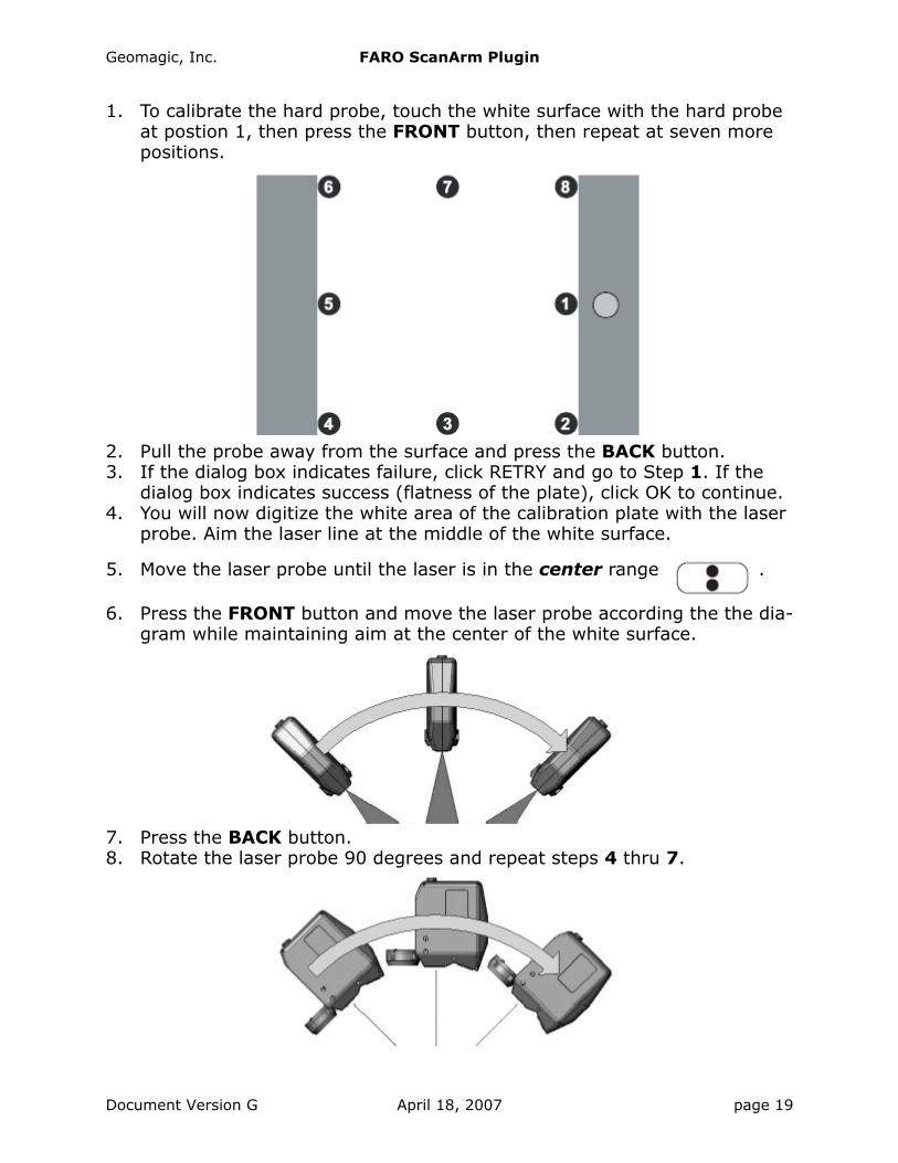
1. To calibrate the hard probe, touch the white surface with the hard probe at postion 1, then press the FRONT button, then repeat at seven more positions.
2. Pull the probe away from the surface and press the BACK button.3. If the dialog box indicates failure, click RETRY and go to Step 1. If the
dialog box indicates success (flatness of the plate), click OK to continue.4. You will now digitize the white area of the calibration plate with the laser
probe. Aim the laser line at the middle of the white surface.
5. Move the laser probe until the laser is in the center range .
6. Press the FRONT button and move the laser probe according the the dia-gram while maintaining aim at the center of the white surface.
7. Press the BACK button.8. Rotate the laser probe 90 degrees and repeat steps 4 thru 7.
Document Version G April 18, 2007 page 19

Geomagic, Inc. FARO ScanArm Plugin
9. You will again digitize the white area of the calibration plate with the laser probe. Aim the laser line at the middle of the white surface.
10. Move the laser probe until the laser is in the near range .
11. Press the FRONT button and move the laser probe to the far range
while maintaining aim at the center of the white surface.
12. Press the BACK button.• If the probe passes the test, the Calibration Status is set to Passed
and the current date and time appear in the time indicator. Click OK. For details on the calibration of both the hard and laser probes, click View Log and see the FaroArm USB manual for details. Calibration of the laser probe is complete.
• If the probe fails the test, the Calibration Status is set to Failed. Click Retry and go to Step 1.
3-2-1 AlignmentThis is a sub-procedure referenced by the Alignment section under Controls and Indicators on page 3.
This describes “3-2-1 Alignment” -- how to specify an object’s coordinate sys-tem by defining the position of three orthogonal planes. The origin of the object’s coordinate system will be the point of intersection of the three planes.
1. Click the large Alignment icon, then the 3-2-1 Alignment
icon.Recall that:The plane orthogonal to the X axis is the YZ plane.The plane orthogonal to the Y axis is the XZ plane.The plane orthogonal to the Z axis is the XY plane.
page 20 April 18, 2007 Document Version G
Geomagic, Inc. FARO ScanArm Plugin
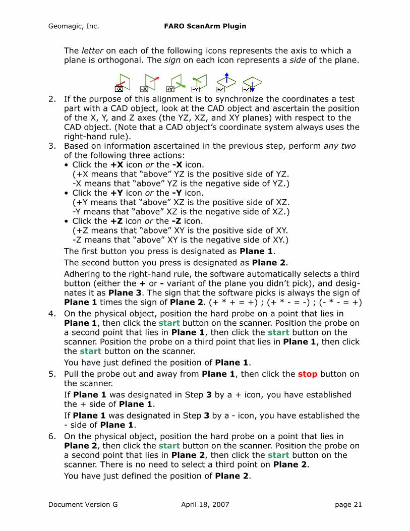
The letter on each of the following icons represents the axis to which a plane is orthogonal. The sign on each icon represents a side of the plane.
2. If the purpose of this alignment is to synchronize the coordinates a test part with a CAD object, look at the CAD object and ascertain the position of the X, Y, and Z axes (the YZ, XZ, and XY planes) with respect to the CAD object. (Note that a CAD object’s coordinate system always uses the right-hand rule).
3. Based on information ascertained in the previous step, perform any two of the following three actions:• Click the +X icon or the -X icon.
(+X means that “above” YZ is the positive side of YZ.-X means that “above” YZ is the negative side of YZ.)
• Click the +Y icon or the -Y icon.(+Y means that “above” XZ is the positive side of XZ.-Y means that “above” XZ is the negative side of XZ.)
• Click the +Z icon or the -Z icon.(+Z means that “above” XY is the positive side of XY.-Z means that “above” XY is the negative side of XY.)
The first button you press is designated as Plane 1.The second button you press is designated as Plane 2.Adhering to the right-hand rule, the software automatically selects a third button (either the + or - variant of the plane you didn’t pick), and desig-nates it as Plane 3. The sign that the software picks is always the sign of Plane 1 times the sign of Plane 2. (+ * + = +) ; (+ * - = -) ; (- * - = +)
4. On the physical object, position the hard probe on a point that lies in Plane 1, then click the start button on the scanner. Position the probe on a second point that lies in Plane 1, then click the start button on the scanner. Position the probe on a third point that lies in Plane 1, then click the start button on the scanner.You have just defined the position of Plane 1.
5. Pull the probe out and away from Plane 1, then click the stop button on the scanner.If Plane 1 was designated in Step 3 by a + icon, you have established the + side of Plane 1.If Plane 1 was designated in Step 3 by a - icon, you have established the - side of Plane 1.
6. On the physical object, position the hard probe on a point that lies in Plane 2, then click the start button on the scanner. Position the probe on a second point that lies in Plane 2, then click the start button on the scanner. There is no need to select a third point on Plane 2.You have just defined the position of Plane 2.
Document Version G April 18, 2007 page 21
Geomagic, Inc. FARO ScanArm Plugin
7. Pull the probe out and away from Plane 2, then click the stop button on the scanner.If Plane 2 was designated in Step 3 by a + icon, you have established the + side of Plane 2.If Plane 2 was designated in Step 3 by a - icon, you have established the - side of Plane 2.
8. On the physical object, position the hard probe on a point that lies in Plane 3, then click the start button on the scanner. There is no need to select a second or third point on Plane 3.
9. Pull the probe out and away from Plane 3, then click the stop button on the scanner.Based on the right-hand rule, the software already knew the + and - side of Plane 3, but this was necessary to complete the process.
10. The current coordinates of the probe appear in a coordinate indicator box. Move the indicator box by dragging it to any location of the screen, or click the stop button to close the indicator. Click Show Coordinates to re-display the coordinate indicator box.
11. Hover the probe above the YZ plane and verify that the X coordinate in the indicator is appropriately positive or negative.Hover the probe above the XZ plane and verify that the Y coordinate in the indicator is appropriately positive or negative.Hover the probe above the XY plane and verify that the Z coordinate in the indicator is appropriately positive or negative.
12. Coordinate system definition is complete. To un-do the coordinate sys-tem, click Reset and go to Step 2.
Detailed Example
To specify the YZ plane (with a total of four points), then the XZ plane (with a total of three points), then the XY plane (with two points): Designate Plane 1 by clicking the +X icon, then designate Plane 2 by clicking the +Y icon. The
page 22 April 18, 2007 Document Version G

Geomagic, Inc. FARO ScanArm Plugin
software automatically designates Plane 3 as +Z. Make nine clicks, some start and some stop, according to the illustration below.
12
3
4
5
6
7
8
9
+X +Y
+Z
YZ plane XZ pla
ne
Denotes clicking the GREEN button on the Faro Arm
Denotes clicking the RED button on the Faro Arm
XY plane
Document Version G April 18, 2007 page 23
Geomagic, Inc. FARO ScanArm Plugin
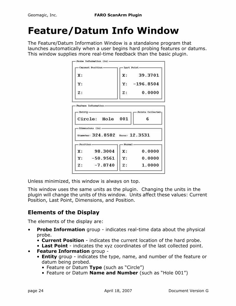
Feature/Datum Info WindowThe Feature/Datum Information Window is a standalone program that launches automatically when a user begins hard probing features or datums. This window supplies more real-time feedback than the basic plugin.
Unless minimized, this window is always on top.
This window uses the same units as the plugin. Changing the units in the plugin will change the units of this window. Units affect these values: Current Position, Last Point, Dimensions, and Position.
Elements of the Display
The elements of the display are:
• Probe Information group - indicates real-time data about the physical probe.• Current Position - indicates the current location of the hard probe.• Last Point - indicates the xyz coordinates of the last collected point.
• Feature Information group - • Entity group - indicates the type, name, and number of the feature or
datum being probed.• Feature or Datum Type (such as “Circle”)• Feature or Datum Name and Number (such as “Hole 001”)
page 24 April 18, 2007 Document Version G
Geomagic, Inc. FARO ScanArm Plugin
• Points Collected group - indicates the number of points collected.• Dimensions group - indicates physical dimensions of the feature or
datum, but only if and when such dimensions can be ascertained.• Diameter (if and when ascertainable) - indicates the diameter of the
feature or datum.• Length and Width (if and when ascertainable) - indicates the length
and width of the feature or datum.• Error - indicates the least squares fitting error. The feature or datum
is refit every time a new point is collected (once enough points are collected to attempt a fitting) and the error for that fit is displayed.
• Position group (if ascertainable) - indicates the xyz coordinates of the center of the feature or datum in real time. Some features and datums have no center, such as a plane.
• Normal group - indicates the normal or axis or direction of the feature or datum.
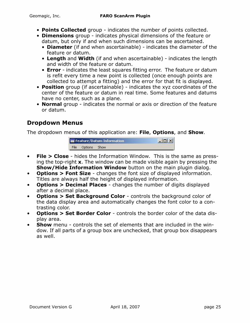
Dropdown Menus
The dropdown menus of this application are: File, Options, and Show.
• File > Close - hides the Information Window. This is the same as press-ing the top-right x. The window can be made visible again by pressing the Show/Hide Information Window button on the main plugin dialog.
• Options > Font Size - changes the font size of displayed information. Titles are always half the height of displayed information.
• Options > Decimal Places - changes the number of digits displayed after a decimal place.
• Options > Set Background Color - controls the background color of the data display area and automatically changes the font color to a con-trasting color.
• Options > Set Border Color - controls the border color of the data dis-play area.
• Show menu - controls the set of elements that are included in the win-dow. If all parts of a group box are unchecked, that group box disappears as well.
Document Version G April 18, 2007 page 25
Geomagic, Inc. FARO ScanArm Plugin
Datum and Feature CreationDatums and features can be created by use of this FARO scanner plugin soft-ware, or by the use of tools that are native to the Geomagic products. In the-ory, datums or features can be identified more precisely by touching the original object and by use of the FARO plugin. Depending on the accuracy of the scan and the user’s experience, however, it may be advantageous to cre-ate datums and features using the native Geomagic tools.To create datums and features using the FARO scanner software:
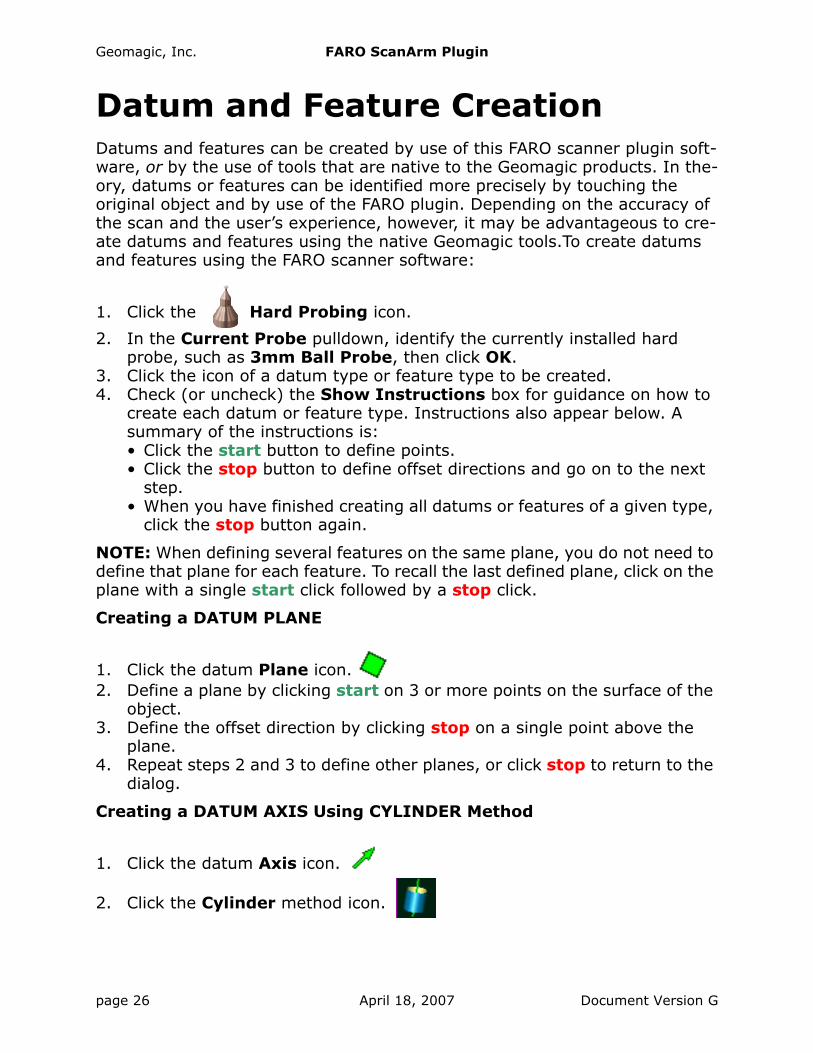
1. Click the Hard Probing icon.
2. In the Current Probe pulldown, identify the currently installed hard probe, such as 3mm Ball Probe, then click OK.
3. Click the icon of a datum type or feature type to be created.4. Check (or uncheck) the Show Instructions box for guidance on how to
create each datum or feature type. Instructions also appear below. A summary of the instructions is:• Click the start button to define points.• Click the stop button to define offset directions and go on to the next
step. • When you have finished creating all datums or features of a given type,
click the stop button again.
NOTE: When defining several features on the same plane, you do not need to define that plane for each feature. To recall the last defined plane, click on the plane with a single start click followed by a stop click.
Creating a DATUM PLANE
1. Click the datum Plane icon.2. Define a plane by clicking start on 3 or more points on the surface of the
object. 3. Define the offset direction by clicking stop on a single point above the
plane.4. Repeat steps 2 and 3 to define other planes, or click stop to return to the
dialog.
Creating a DATUM AXIS Using CYLINDER Method
1. Click the datum Axis icon.
2. Click the Cylinder method icon.
page 26 April 18, 2007 Document Version G
Geomagic, Inc. FARO ScanArm Plugin
3. Define a cylinder by clicking start on 6 or more points on the surface of the object.
4. Define the axial direction by clicking stop on a single point inside or out-side the cylinder.
5. Repeat steps 3 and 4 to define other axes, or click stop to return to the dialog.
Creating a DATUM AXIS Using CONE method:
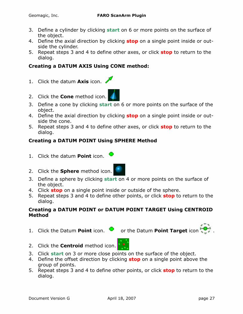
1. Click the datum Axis icon.
2. Click the Cone method icon.
3. Define a cone by clicking start on 6 or more points on the surface of the object.
4. Define the axial direction by clicking stop on a single point inside or out-side the cone.
5. Repeat steps 3 and 4 to define other axes, or click stop to return to the dialog.
Creating a DATUM POINT Using SPHERE Method
1. Click the datum Point icon.
2. Click the Sphere method icon.
3. Define a sphere by clicking start on 4 or more points on the surface of the object.
4. Click stop on a single point inside or outside of the sphere.5. Repeat steps 3 and 4 to define other points, or click stop to return to the
dialog.
Creating a DATUM POINT or DATUM POINT TARGET Using CENTROID Method
1. Click the Datum Point icon. or the Datum Point Target icon .
2. Click the Centroid method icon.
3. Click start on 3 or more close points on the surface of the object.4. Define the offset direction by clicking stop on a single point above the
group of points.5. Repeat steps 3 and 4 to define other points, or click stop to return to the
dialog.
Document Version G April 18, 2007 page 27
Geomagic, Inc. FARO ScanArm Plugin
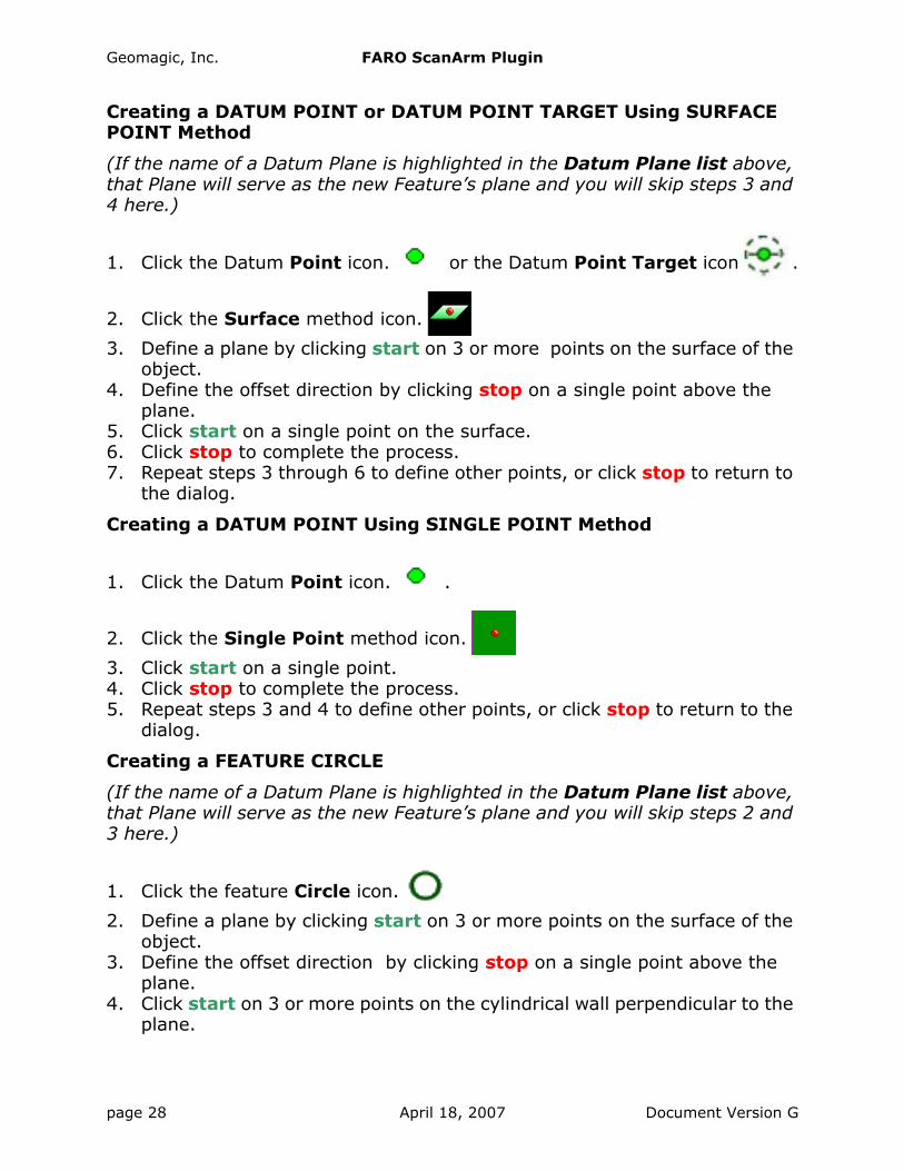
Creating a DATUM POINT or DATUM POINT TARGET Using SURFACE POINT Method
(If the name of a Datum Plane is highlighted in the Datum Plane list above, that Plane will serve as the new Feature’s plane and you will skip steps 3 and 4 here.)
1. Click the Datum Point icon. or the Datum Point Target icon .
2. Click the Surface method icon.
3. Define a plane by clicking start on 3 or more points on the surface of the object.
4. Define the offset direction by clicking stop on a single point above the plane.
5. Click start on a single point on the surface.6. Click stop to complete the process.7. Repeat steps 3 through 6 to define other points, or click stop to return to
the dialog.
Creating a DATUM POINT Using SINGLE POINT Method
1. Click the Datum Point icon. .
2. Click the Single Point method icon.
3. Click start on a single point.4. Click stop to complete the process.5. Repeat steps 3 and 4 to define other points, or click stop to return to the
dialog.
Creating a FEATURE CIRCLE
(If the name of a Datum Plane is highlighted in the Datum Plane list above, that Plane will serve as the new Feature’s plane and you will skip steps 2 and 3 here.)
1. Click the feature Circle icon.
2. Define a plane by clicking start on 3 or more points on the surface of the object.
3. Define the offset direction by clicking stop on a single point above the plane.
4. Click start on 3 or more points on the cylindrical wall perpendicular to the plane.
page 28 April 18, 2007 Document Version G

Geomagic, Inc. FARO ScanArm Plugin
5. Define the offset direction by clicking stop on a single point inside the cir-cle (to make a hole) or outside the circle (to make a protrusion).
6. Repeat steps 2 through 5 to define other circles, or click stop to return to the dialog.
Creating a FEATURE SLOT
(If the name of a Datum Plane is highlighted in the Datum Plane list above, that Plane will serve as the new Feature’s plane and you will skip steps 2 and 3 here.)
1. Click the feature Slot icon.
2. Define a plane by clicking start on 3 or more points on the surface of the object using the start button.
3. Define the offset direction by clicking stop on a single point above the plane.
4. Click start on 3 or more points on the cylindrical wall of one end of the slot perpendicular to the plane.
5. Define the offset direction by clicking stop on a single point inside the slot (to make a hole) or outside the slot (to make a protrusion).
6. Repeat steps 4 and 5 to define the opposite end of the slot.7. Repeat steps 2 through 6 to define other slots, or click stop to return to
the dialog.
Creating a FEATURE RECTANGLE
(If the name of a Datum Plane is highlighted in the Datum Plane list above, that Plane will serve as the new Feature’s plane and you will skip steps 2 and 3 here.)
1. Click the feature Rectangle icon.
2. Define a plane by clicking start on on 3 or more points on the surface of the object using the start button.
3. Define the offset direction by clicking stop on a single point above the plane.
4. Click start on 2 or more points on one of the rectangular walls perpendic-ular to the plane.
5. Define the offset direction by clicking stop on a single point away from the rectangle wall.
6. Repeat steps 4 and 5 for the remaining three walls, working in a counter-clockwise order.
7. Repeat steps 2 through 6 to define other rectangles, or click stop to return to the dialog.
Document Version G April 18, 2007 page 29
Geomagic, Inc. FARO ScanArm Plugin
Creating a FEATURE LINE
(If the name of a Datum Plane is highlighted in the Datum Plane list above, that Plane will serve as the new Feature’s plane and you will skip steps 2 and 3 here.)
1. Click the feature Line icon (for the intersection of two planes)
2. Click start on 3 or more points on the surface of the object. 3. Define the offset direction by clicking stop on a single point above the
plane.4. Click start on 2 or more points on a rectangular wall perpendicular to the
plane.5. Define the offset direction by clicking stop on a single point away from
the wall.6. Repeat steps 2 through 5 to define other lines, or click stop to return to
the dialog.
Special Use of Del Key During Feature and Datum Creation
During the hard-probing of a feature or datum, the most recently probed point appears in red in the Viewing Area. (After the hard-probing of a feature or datum -- after you probe the offset, all points revert to black.) To delete the most recent (red) point, press the Del key. Press Del again to delete the second most recent point, or repeatedly to delete all points.
When the hard-probing of a feature or datum is complete (when you have probed the offset, and points in the Viewing Area have reverted to black), you can start probing the points of a new feature or datum, stop the probing pro-cess and return to the dialog, or press Del to delete the most recent feature or datum.
Move Device“Move Device” is a specialized procedure for aligning the multiple scans of objects that are larger than the reach of the arm. It involves the hard-probing of reference points, moving the object or the arm itself, and hard-probing of the same reference points to re-establish bearings.
The following summary describes a process of scanning, moving the scanner because the object is large, and continuing with the scan.
1. Scan part of an object.2. If “Move Device” is not necessary, save the scan by pressing OK.
page 30 April 18, 2007 Document Version G
Geomagic, Inc. FARO ScanArm Plugin
If “Move Device” is necessary (because space or the length of the arm did not allow a complete scan), press the Alignment icon button.
3. Press the Move Device Wizard button.4. In the Move Device Wizard, click Begin.5. On the Reference Point Collection Panel, use the hard probe to identify
four to seven reference points on the physical object, each by one of four methods. On paper, write the name of each point, its location and identi-fication method. Then click Next.
6. In response to a prompt, move the physical part or the scanner itself, then click OK.
7. On the Target Point Collection Panel, use the hard probe to re-identify the named reference points. As a result, the software can recalculate the ori-entation of the scanner with respect to the physical object. The next scan will be a continuation of the previous scan. Press Next.
8. On the Correspondence Report Panel, the software displays the precision to which it was able to associate the target points to the reference points. Eliminate any associations that are unacceptable, then press Done to specify that reference points and target points are sufficiently “con-nected.” Go to Step 1 to scan more of the same physical object.
The detailed process is:
1. Press the Laser Scan icon button, then Start Scan. Scan as much of the physical object as space or the length of the arm allows.
2. If “Move Device” is not necessary, save the scan by pressing OK.If “Move Device” is necessary (because space or the length of the arm did not allow a complete scan), press the Alignment icon button.
3. Press the Move Device Wizard button. The Move Device Wizard group appears on the dialog.
Document Version G April 18, 2007 page 31

Geomagic, Inc. FARO ScanArm Plugin
4. This is the “Move Device” Home Panel. It has two buttons:• Begin button - begins a new “Move Device” process. Go to the Refer-
ence Point Collection Panel in Step 5.• Resume button - returns to the panel on which you previously
pressed Exit and saved the state of the “Move Device” process: the Reference Point Collection Panel in Step 5, the Target Point Collection Panel in Step 7, or the Correspondence Report Panel in Step 8.
5. On the Reference Point Collection Panel, use the hard probe to identify four to eight reference points on the physical object, each by one of three methods described below, or click Previous Targets to re-use the set of
“Move Device” Home Panel
page 32 April 18, 2007 Document Version G
Geomagic, Inc. FARO ScanArm Plugin
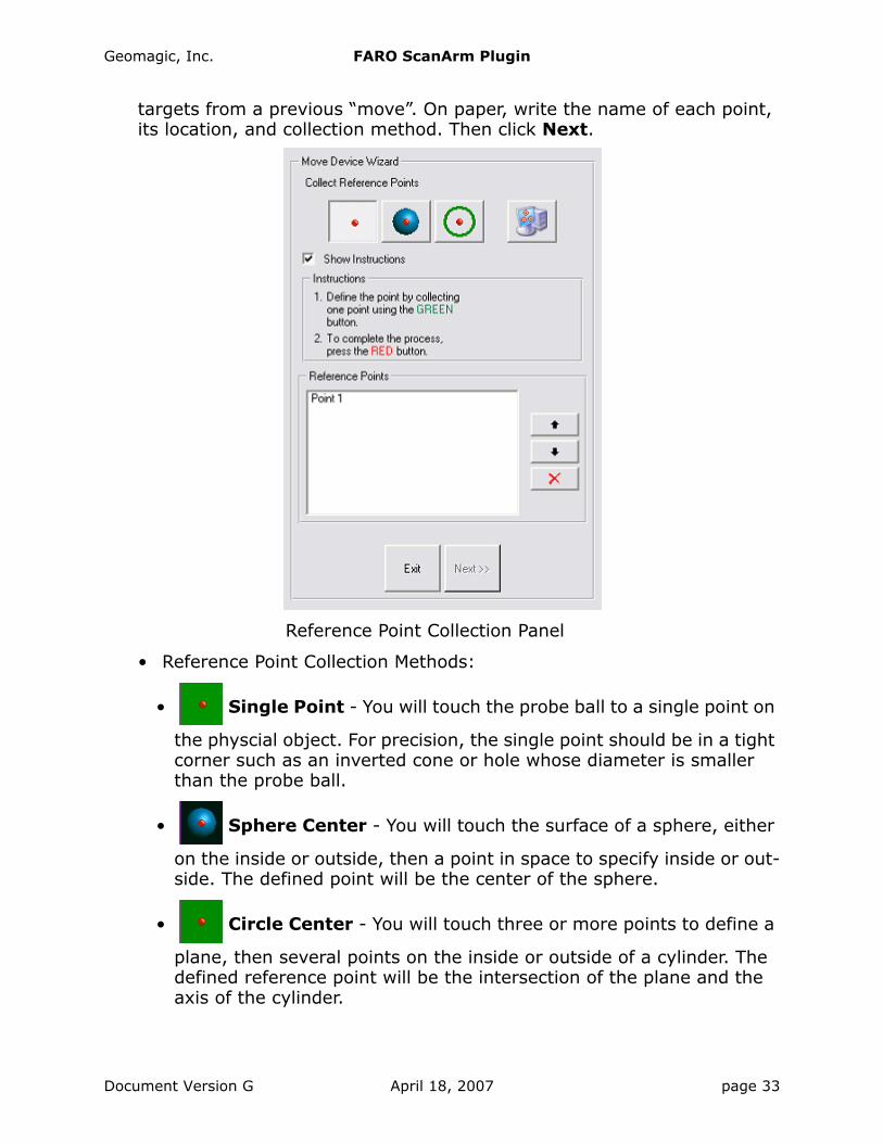
targets from a previous “move”. On paper, write the name of each point, its location, and collection method. Then click Next.
• Reference Point Collection Methods:
• Single Point - You will touch the probe ball to a single point on
the physcial object. For precision, the single point should be in a tight corner such as an inverted cone or hole whose diameter is smaller than the probe ball.
• Sphere Center - You will touch the surface of a sphere, either
on the inside or outside, then a point in space to specify inside or out-side. The defined point will be the center of the sphere.
• Circle Center - You will touch three or more points to define a
plane, then several points on the inside or outside of a cylinder. The defined reference point will be the intersection of the plane and the axis of the cylinder.
Reference Point Collection Panel
Document Version G April 18, 2007 page 33
Geomagic, Inc. FARO ScanArm Plugin
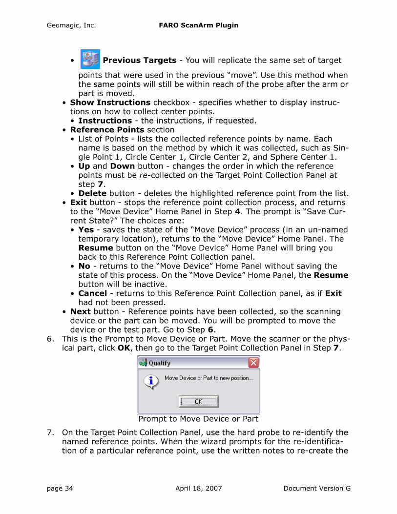
• Previous Targets - You will replicate the same set of target
points that were used in the previous “move”. Use this method when the same points will still be within reach of the probe after the arm or part is moved.
• Show Instructions checkbox - specifies whether to display instruc-tions on how to collect center points.• Instructions - the instructions, if requested.
• Reference Points section• List of Points - lists the collected reference points by name. Each
name is based on the method by which it was collected, such as Sin-gle Point 1, Circle Center 1, Circle Center 2, and Sphere Center 1.
• Up and Down button - changes the order in which the reference points must be re-collected on the Target Point Collection Panel at step 7.
• Delete button - deletes the highlighted reference point from the list.• Exit button - stops the reference point collection process, and returns
to the “Move Device” Home Panel in Step 4. The prompt is “Save Cur-rent State?” The choices are:• Yes - saves the state of the “Move Device” process (in an un-named
temporary location), returns to the “Move Device” Home Panel. The Resume button on the “Move Device” Home Panel will bring you back to this Reference Point Collection panel.
• No - returns to the “Move Device” Home Panel without saving the state of this process. On the “Move Device” Home Panel, the Resume button will be inactive.
• Cancel - returns to this Reference Point Collection panel, as if Exit had not been pressed.
• Next button - Reference points have been collected, so the scanning device or the part can be moved. You will be prompted to move the device or the test part. Go to Step 6.
6. This is the Prompt to Move Device or Part. Move the scanner or the phys-ical part, click OK, then go to the Target Point Collection Panel in Step 7.
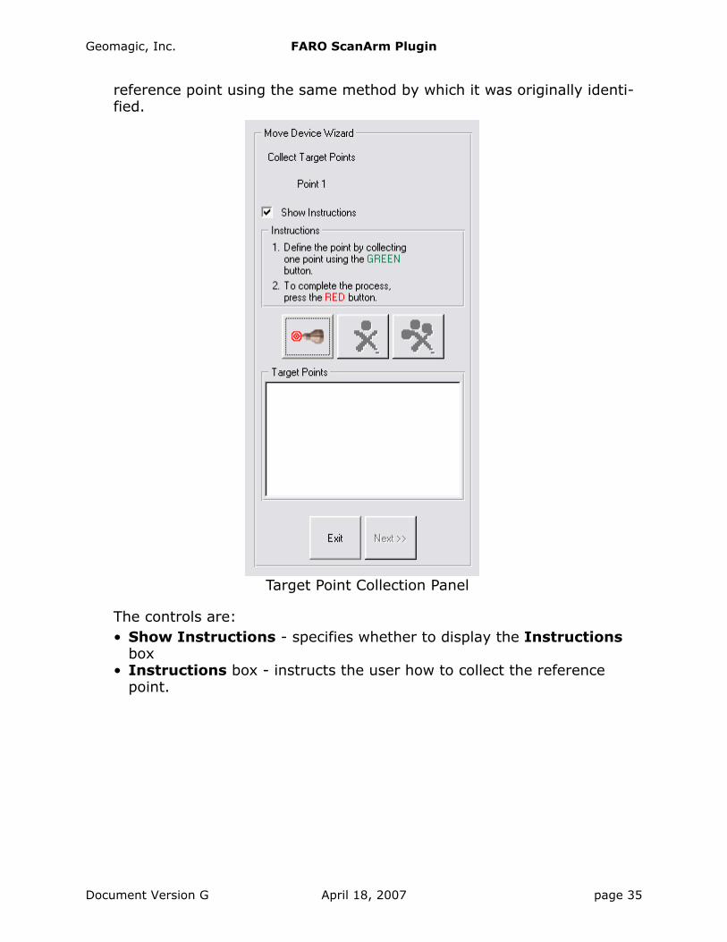
7. On the Target Point Collection Panel, use the hard probe to re-identify the named reference points. When the wizard prompts for the re-identifica-tion of a particular reference point, use the written notes to re-create the
Prompt to Move Device or Part
page 34 April 18, 2007 Document Version G
Geomagic, Inc. FARO ScanArm Plugin
reference point using the same method by which it was originally identi-fied.
The controls are:• Show Instructions - specifies whether to display the Instructions
box• Instructions box - instructs the user how to collect the reference
point.
Target Point Collection Panel
Document Version G April 18, 2007 page 35

Geomagic, Inc. FARO ScanArm Plugin
• Define Targets button - press this to re-start the identification
of targets (to re-start identifying the points that were previously identi-fied as reference points). When this dialog first pops up, it is already in target collection mode, so use this button to re-start the process if you have pressed the stop button on the scanner.
• Re-Define Last Target icon button - after pressing the stop
button on the scanner to stop collection, press this to delete the most recently collected target point and to automatically re-start the identifi-cation of targets.
• Clear All Targets icon button - after pressing the stop button
on the scanner to stop collection, press this to delete all collected target points. To re-start collection of target points, you must press the Define Targets button.
• Exit button - stops the target point collection process, and returns to the “Move Device” Home Panel in Step 4. The prompt is “Save Current State?” The choices are:• Yes - saves the state of the “Move Device” process (in an un-named
temporary location), returns to the “Move Device” Home Panel. The Resume button on the “Move Device” Home Panel will bring you back to this Target Point Collection panel.
• No - returns to the “Move Device” Home Panel without saving the state of this process. On the “Move Device” Home Panel, the Resume button will be inactive.
• Cancel - returns to this Target Point Collection panel, as if Exit had not been pressed.
• Next button - Press this when all reference points have been re-identi-fied by use of the hard probe. Go to the Correspondence Report Panel in Step 8.
8. The Correspondence Report Panel displays the precision to which the software was able to associate the target points to the reference points. Eliminate any associations that are unacceptable, then press Done to
page 36 April 18, 2007 Document Version G

Geomagic, Inc. FARO ScanArm Plugin
specify that reference points and target points are sufficiently “con-nected.” Go to Step 1 to scan more of the same physical object.
The controls and indicators are:• Best Fit Result list - a list of the associations of target points to refer-
ence points.• Delete button (applicable only when there are four or more point pairs
in the Best Fit Result list) - allows any target/reference pair to be deleted from the result list. When a pair is deleted, the data is lost and the remaining paris are immediately re-evaluated.
• Datum Deviations list - displays the precision to which each of the reference/target pairs was associated. A pair with a large deviation was not scanned precisely enough, and may be hindering the best-fit more than it is helping, and is therefore a candidate for deletion.
• Done button - Press this to accept this set of reference points and associated target points (and modify the cumulative transformation matrix) and return to the Faro Scanning panel (in Step 1) for continua-tion of the scan process.
Correspondence Report Panel
Document Version G April 18, 2007 page 37
Geomagic, Inc. FARO ScanArm Plugin
Detailed ExamplesThis section contains examples that are referenced earlier in this document.
ALIGNING TEST AND REFERENCE PARTS WITH GEOMAGIC QUALIFY
If a hard probe is installed with the laser equipment, use the variant of this procedure called “Hard Probe Technique”. If no hard probe is installed, use the variant called “Laser Technique”.
1. Load a CAD object into the Model Manager and designate it as the refer-ence object.
2. Perform one of the following:• Hard-Probe Technique - use Tools > Datums > Create Datums or
Tools > Features > Create Features to create datums and features on the reference object.
• Laser Technique - Continue to the next step.3. Start the scanner plugin.4. Perform one of the following:
• Hard-Probe Technique - Hard probe the corresponding datums and fea-tures on a test object that is resting in a test fixture (without laser scanning the test object). The datums and features become sub-objects of a special special “blank” test object named “Features/Datums” that records the position of the datums and features with respect to the test fixture.
• Laser Technique - Scan a portion of the object, at least enough points that it could be aligned to the reference object using the best-fit align-ment function of Geomagic Qualify.
5. Exit the plugin by clicking the OK button.• Hard-Probe Technique - In the Model Manager, note the existence of
the CAD object and the new test object called “Features/Datums”. Note the existence of feature and datum sub-objects under the Features/Datums object.
• Laser Technique - Continue to the next step.6. Perform one of the following:
• Hard-Probe Technique - Use Tools > Alignment > Datum/Features Alignment on the test and reference objects (which aligns the refer-ence object with the special test object by aligning their common datums and features).
• Laser Technique - Use Tools > Alignment > Best Fit Alignment on the test and reference objects (which aligns the reference object with the test object by detecting the similarity of their surfaces.
The side effect of this process is that it creates an internal transformation matrix, which is a mapping of the spatial difference between the refer-ence object and the test object. In this case, the transformation matrix
page 38 April 18, 2007 Document Version G

Geomagic, Inc. FARO ScanArm Plugin
represents the spatial difference between the reference object and the place where a test object will lie in the test fixture.
7. Place a real test part in the test fixture.8. Start the scanner plugin again.9. Click the large Laser icon to activate scanning mode. Begin scanning.
Scan data appears on the screen in alignment with the CAD reference object.
10. Exit the plugin by clicking the OK button. In the Model Manager, notice that the newly created scan object is now the test object.
11. To prepare to scan another test object, go to step 8. Every new test object will be aligned correctly.
EXAMPLE OF LASER SCANNING
1. Click the Laser Scanning icon.
2. In the Current Probe pulldown, select Laser Probe then click OK.3. In the Laser Capture dialog, Data Options section, pick a Data For-
mat. This specifies whether future scan(s) will be stored in the Model Manager as ordered data, unordered data, or as both (in two separate objects). With Geomagic Qualify, you probably want unordered data because it is an exact representation of the object and lends itself to inspection. With Geomagic Studio, you probably want ordered data because it is easier to handle during an engineering process.
4. In the Laser Capture dialog, Object Options section, pick a Store Data In option. This controls whether the scan data will go to the Model Manager as: a new object in a new object group, as a new stand-alone object that is not in an object group, as data to be appended to an exist-ing scan object, or as a new object in an existing object group. Your choice depends on how you like to organize scan data.
5. To perform a scan and thus transfer data to the Geomagic Model Man-ager:
• Click the Start Capture icon .
• Click the start button on the scanner and make scan passes.• During the scanning process, use the on-screen range finder or the
LEDs on the scanner to keep the scanner at a suitable distance from the physical object.
• At any time, click the start button again to pause scanning. The scan arm acts as a virtual camera when scanning is not active. Click the start button to resume scanning.
• Click the stop button to end scanning. The scan arm behaves like a mouse.
6. If all scanning is complete, press OK to close the plugin.7. If it is necessary to change the Data Format option, go back to Step 3.
Document Version G April 18, 2007 page 39
Geomagic, Inc. FARO ScanArm Plugin
8. If it is necessary to change the Store Data In option, go back to Step 4.9. Go to Step 5 and perform the next scan.
EXAMPLE OF Laser Compare
This section describes the concepts of computer-aided inspection with Geo-magic Qualify and any Geomagic scanner plugin.
1. The first step of a CAI process is to align the coordinate system of a refer-ence object to the scanner so that collected data can be compared to the reference object in the same coordinate system. Use one of the alignment methods summaraized at Hardware Alignment on page 3.
2. Next, designate a CAD object as the reference object in the Geomagic Model Manager.
3. Click the Laser Compare icon button.4. Click the Calibrate Scanner or Scanner Options icon button if neces-
sary.5. Click the Initialize button. The Start Capture icon button becomes
active. 6. To perform a scan and thus transfer unordered (raw) data to the Geo-
magic Model Manager:
• Click the Start Capture icon .
• Click the start button on the scanner and make scan passes.• During the scanning process, use the on-screen range finder or the
LEDs on the scanner to keep the scanner at a suitable distance from the physical object.
• At any time, click the start button again to pause scanning. The scan arm acts as a virtual camera when scanning is not active. Click the start button to resume scanning.
• Click the stop button to end scanning. The scan arm behaves like a mouse.
7. If the physical part is larger than the reach of the scan arm, go to Move Device on page 30, then return to this step.
8. If more scanning is necessary, go to Step 6.9. When scanning is complete, click OK on the dialog. Scanned data is
saved into the Geomagic Model Manager, the saved object is automati-cally designated as the test object in the Model Manager, and the compar-ison results are saved to a Result object in the Model Manager.
page 40 April 18, 2007 Document Version G