Farm Tube Bin Unload System - grain augers are advised to retain documentary evidence that this...
50
Read this manual before using product. Failure to follow instructions and safety precautions can result in serious injury, death, or property damage. Keep manual for future reference. Part Number: BU-0101703 R3 Revised: July 2017 Farm Tube Bin Unload System 100 Series Operator’s Manual This manual applies to: 8” Tube Unload Bin Diameters: 24’, 27’, 30’, 33’, 36’, 39’, 42’, 45’, 48’, 54’, 60’ 10” Tube Unload Original Instructions
Transcript of Farm Tube Bin Unload System - grain augers are advised to retain documentary evidence that this...

Read this manual before using product. Failure tofollow instructions and safety precautions canresult in serious injury, death, or propertydamage. Keep manual for future reference.
Part Number: BU-0101703 R3Revised: July 2017
Farm Tube Bin Unload System100 SeriesOperator’s Manual
This manual applies to:
8” Tube Unload Bin Diameters: 24’, 27’, 30’, 33’, 36’,39’, 42’, 45’, 48’, 54’, 60’10” Tube Unload
Original Instructions

We strongly recommend that all personnel associated with this equipment be trained in the correct operationaland safety procedures required for this product. This product has been designed and constructed according togeneral engineering standards, other local regulations may apply and must be followed by the operator. Use thesign-off sheet below to record initial and periodic reviews of this manual with all such personnel.
Date Employee Signature Employer Signature

FARM TUBE BIN UNLOAD SYSTEM – 100 SERIES
BU-0101703 R3 3
CONTENTS1. Introduction ............................................................................................................................................ 5
1.1. Serial Number Location............................................................................................................ 51.2. Intended Use ............................................................................................................................ 6
1.2.1 Misuse ........................................................................................................................ 6
2. Safety....................................................................................................................................................... 72.1. Safety Alert Symbol and Signal Words..................................................................................... 72.2. General Safety .......................................................................................................................... 72.3. Rotating Flighting Safety .......................................................................................................... 82.4. Rotating Parts Safety................................................................................................................ 82.5. Work Area Safety ..................................................................................................................... 82.6. Guards Safety ........................................................................................................................... 82.7. Bin Unloading Safety ................................................................................................................ 82.8. Bin Entry Safety ........................................................................................................................ 9
2.8.1 Roof Entry................................................................................................................... 92.9. Bin Emergency Entry ................................................................................................................ 92.10. Bin Entrapment ...................................................................................................................... 9
2.10.1 Flowing Grain ......................................................................................................... 102.10.2 Collapse of Bridged Grain....................................................................................... 102.10.3 Collapse of a Vertical Wall of Grain ....................................................................... 11
2.11. Combustible Dust ................................................................................................................. 122.12. Drives and Lockout Safety.................................................................................................... 12
2.12.1 Electric Motor Safety.............................................................................................. 132.13. Personal Protective Equipment............................................................................................ 132.14. Safety Equipment ................................................................................................................. 142.15. Safety Decals ........................................................................................................................ 14
2.15.1 Decal Installation/Replacement............................................................................. 142.15.2 Safety Decal Locations and Details ........................................................................ 15
3. Features................................................................................................................................................. 21
4. Operation .............................................................................................................................................. 224.1. Operation Safety .................................................................................................................... 224.2. Overview................................................................................................................................. 224.3. Before Filling the Bin with Grain ............................................................................................ 234.4. Operating Controls ................................................................................................................. 234.5. Operation of the Bin Unload System ..................................................................................... 244.6. Emergency Shutdown ............................................................................................................ 254.7. Emergency Sump.................................................................................................................... 254.8. Restarting with a Full Underfloor Auger ................................................................................ 254.9. Cleanup................................................................................................................................... 264.10. Relocating the Electric Drive to Another Grain Bin ............................................................. 264.11. Extended Shutdown / End of Season................................................................................... 27
5. Maintenance ......................................................................................................................................... 285.1. Maintenance Safety ............................................................................................................... 285.2. Maintenance Schedule........................................................................................................... 285.3. Visually Inspect the Equipment.............................................................................................. 295.4. Clean and Wash the Equipment ............................................................................................ 295.5. Check the Gearbox Oil............................................................................................................ 29

FARM TUBE BIN UNLOAD SYSTEM – 100 SERIES
4 BU-0101703 R3
5.6. Change the Gearbox Oil ......................................................................................................... 305.7. Tension the Drive Belts .......................................................................................................... 305.8. Align the Drive Belts............................................................................................................... 325.9. Replace the Drive Belts .......................................................................................................... 325.10. Replace the Sweep Drive Wheel.......................................................................................... 325.11. Adjust the Bin Sweep Backboard ......................................................................................... 345.12. Adjust the Bin Sweep Engage Handle .................................................................................. 35
6. Troubleshooting.................................................................................................................................... 36
7. Specifications ........................................................................................................................................ 397.1. Dimensions ............................................................................................................................. 407.2. Models .................................................................................................................................... 467.3. Power Requirements.............................................................................................................. 47
8. Bin Unload Limited Warranty .............................................................................................................. 48

BU-0101703 R3 5
1. IntroductionThank you for purchasing a Westfield Farm Tube Bin Unload System. This equipment will allow safeand efficient operation when you read and follow all of the instructions contained in this manual. Withproper care, your bin unload will provide you with many years of trouble-free operation.
Keep this manual handy for frequent reference and to review with new personnel. A sign-off form isprovided on the inside front cover for your convenience. If any information in this manual is notunderstood or if you need additional information, please contact your local distributor or dealer forassistance.
This manual should be regarded as part of the equipment. Suppliers of both new and second-handequipment are advised to retain documentary evidence that this manual was provided with theequipment.
1.1. Serial Number LocationAlways give your dealer the serial number on your bin unload (shown below) when ordering parts or requestingservice or other information. Please record this information in the table below for easy reference.
Model Number
Serial Number
Date Received
FARM TUBE BIN UNLOAD SYSTEM – 100 SERIES 1. INTRODUCTION

6 BU-0101703 R3
1.2. Intended UseThe bin unload is designed solely for use in the intended agricultural use as listed below. Use in any other way isconsidered as contrary to the intended use. Compliance with and strict adherence to the conditions ofoperation and maintenance as specified by the manufacturer, also constitute essential elements of the intendeduse.
The bin unload should be operated, maintained, serviced, and repaired only by persons who are familiar with itsparticular characteristics and who are acquainted with the relevant safety procedures.
Accident prevention regulations and all other generally recognized regulations on safety and occupationalmedicine must be observed at all times.
Any modifications made to the bin unload may relieve the manufacturer of liability for any resulting damage orinjury.
Intended use for the bin unload:• Handling grain, pulse crops, treated seeds, or other similar materials.
Use in any other way is considered as contrary to the intended use and is not covered by the warranty.
1.2.1 MisuseDo not use the bin unload for:
• transferring material other than dry, free-flowing food-grains.
• commercial or off-farm use.
1. INTRODUCTION FARM TUBE BIN UNLOAD SYSTEM – 100 SERIES

BU-0101703 R3 7
2. Safety2.1. Safety Alert Symbol and Signal Words
This safety alert symbol indicates important safety messages in this manual. When you seethis symbol, be alert to the possibility of injury or death, carefully read the message thatfollows, and inform others.
Signal Words: Note the use of the signal words DANGER,WARNING, CAUTION, and NOTICE with the safetymessages. The appropriate signal word for each message has been selected using the definitions below as aguideline.
Indicates an imminently hazardous situation that, if not avoided, will result in serious injury ordeath.Indicates a hazardous situation that, if not avoided, could result in serious injury or death.
Indicates a hazardous situation that, if not avoided, may result in minor or moderate injury.
Indicates a potentially hazardous situation that, if not avoided, may result in property damage.
2.2. General SafetyThe safety information in the safety section of this manual applies to all safety practices. Specific safetyinformation (such as Operation Safety), can be found in the appropriate section.
YOU are responsible for the SAFE use and maintenance of your bin unload. YOU must ensure that you andanyone else who is going to work around the bin unload understands all procedures and related SAFETYinformation contained in this manual.
Remember, YOU are the key to safety. Good safety practices not only protect you, but also the people aroundyou. Make these practices a working part of your safety program. All accidents can be avoided.
• It is the bin unload owner, operator, and maintenance personnel's responsibility toread and understand ALL safety instructions, safety decals, and manuals and followthem when assembling, operating, or maintaining the equipment.
• Owners must give instructions and review the information initially and annually with all personnel beforeallowing them to operate the bin unload. Untrained users/operators expose themselves and bystanders topossible serious injury or death.
• The bin unload is not intended to be used by children.
• Use the bin unload for its intended purposes only.
• Do not modify the bin unload in any way without written permission from the manufacturer. Unauthorizedmodification may impair the function and/or safety, and could affect the life of the bin unload. Anyunauthorized modification of the bin unload will void the warranty.
FARM TUBE BIN UNLOAD SYSTEM – 100 SERIES 2. SAFETY

8 BU-0101703 R3
2.3. Rotating Flighting Safety
• KEEP AWAY from rotating flighting.
• DO NOT remove or modify flighting guards, doors, or covers.Keep in good working order. Have replaced if damaged.
• DO NOT operate the bin unload without all guards, doors,and covers in place.
• NEVER touch the flighting. Use a stick or other tool toremove an obstruction or clean out.
• Shut off and lock out power to adjust, service, or clean.
2.4. Rotating Parts Safety
• Keep body, hair, and clothing away from rotating pulleys,belts, chains, and sprockets.
• Do not operate with any guard removed or modified. Keepguards in good working order.
• Shut off and remove key or lock out power source beforeinspecting or servicing machine.
2.5. Work Area Safety• Have another trained person nearby who can shut down the bin unload in case of accident.
• The work area should be kept clear of bystanders.
• Keep the work area clean and free of debris.
2.6. Guards Safety
• Keep guards in place and do not operate unless all guards are in place.
• Do not walk on, step on, or damage guards.
• Lock out power before removing a guard.
• Ensure all guards are replaced after performing maintenance.
2.7. Bin Unloading Safety
• Never enter a bin when loading or unloading.
• Unload only as described in the operation section of this manual.
• Lock the bin door (where equipped) and close/lock all other access doors when not in use.
2. SAFETY FARM TUBE BIN UNLOAD SYSTEM – 100 SERIES

BU-0101703 R3 9
2.8. Bin Entry SafetyThe information in this section applies to entry through any access point.
Always try to work and solve problems without entering a bin.If you must enter the bin, follow the safety information below to safely enter through theroof or door:
• Stop the unloading process if the bin is being unloaded and lockout/tagout power beforeentering the bin, refer to Lockout/Tagout Safety.
• Always wear a dust-filtering respirator when entering the bin. Grain dust and spores wheninhaled into the lungs can cause severe reactions leading to hospitalization in some cases.Persistent exposure may cause “farmer’s lung,” which can eventually be fatal.
• Before working inside the bin, ventilate the area by opening the vent or by other equivalentmeans to force air into the bin to prevent oxygen-deficient atmosphere. Inadequate oxygenis very harmful to your health and can cause death. Exposure to carbon dioxide can causedrowsiness, headache and even death due to suffocation. Test the atmosphere. If thecarbon dioxide hazard cannot be reduced or eliminated or you cannot test the atmosphere,use correctly fitted and appropriate respirator.
• Never walk on grain to make it flow.
If you ignore the safety precautions above and enter the bin, you could die from being submerged.
2.8.1 Roof EntryThe information in this section applies to entry through the bin roof only.
• Never enter a bin from the roof if you don’t know its unloading history. Bridges of storedmaterial can form above a void space below, causing potential for entrapment.
• Have body harness tethered to a lifeline controlled by two others outside the bin. Oneworker should be able to see inside worker through the inspection hatch. If there is anaccident, one worker can focus on the victim while the other goes/calls for help.
• In the event that you are trapped in the bin as it is unloading, move as quickly as possibletoward the bin wall; keep yourself elevated above the material by walking on the flowingmass while staying as close as possible to the bin wall.
2.9. Bin Emergency EntryIn an emergency situation:
• Follow protocols set by your local occupational safety and health agency.
• If you need to rescue somebody inside the bin, call emergency responders and only attempt to rescue usingnon-entry rescue procedure/equipment. Do not enter the bin unless you are trained for rescue, equipped andrelieved.
2.10. Bin EntrapmentIt takes more than 1000 lb (4.5kN) of force to remove someone buried below the surface.
The following sections cover common ways a person gets submerged or trapped:
FARM TUBE BIN UNLOAD SYSTEM – 100 SERIES 2. SAFETY

10 BU-0101703 R3
2.10.1 Flowing GrainThis procedure may also apply to fertilizer where the bin is intended for fertilizer storage.
• Grain flows in a funnel-shaped path when unloading. This vortex of grain behaves very much like a waterdrain. Velocity increases as grain flows from the bin wall at the top of the grain mass into a small verticalcolumn at the center of the bin.
• Flowing grain will not support the weight of a person. Submersion happens within seconds.
Figure 1. Bin Suffocation Hazards in Flowing Grain
2.10.2 Collapse of Bridged GrainThis procedure may also apply to fertilizer where the bin is intended for fertilizer storage.
2. SAFETY FARM TUBE BIN UNLOAD SYSTEM – 100 SERIES

BU-0101703 R3 11
• Grain can “bridge” across a bin, creating an empty air space below. A person can easily break through thisbridge and become trapped, risking suffocation.
• To identify bridged grain, look for a funnel shape on the surface of the grain after having removed some ofthe grain. If surface is undisturbed, the grain has bridged and formed a crust.
• Never walk on the grain crust. The crust rarely becomes strong enough to support the weight of a person.
• To remove bridge, try breaking the bridge from the inspection hatch or filler cap. Use a pole to hit thesurface, securing it with a rope in case it is dropped. Be aware that chunks of crusted grain can move downto the auger and limit flow.
Figure 2. Bin Suffocation Hazards in Bridged Grain
2.10.3 Collapse of a Vertical Wall of GrainThis procedure may also apply to fertilizer where the bin is intended for fertilizer storage.
• Vertical walls of grain are created when the bin is partially empty. Poking at the wall can make the grainavalanche and submerge a person.
• Do not enter bin to break down grain that has set up. Break grain mass from top of bin outside.
FARM TUBE BIN UNLOAD SYSTEM – 100 SERIES 2. SAFETY

12 BU-0101703 R3
Figure 3. Bin Suffocation Hazards from a Vertical Grain Wall
2.11. Combustible Dust
The bin unload has been designed for safe use in areas where hazards due to combustible dustmay potentially occur. To fully minimize the risk of a dust explosion:
• Clean up dust deposits after operation of the equipment.
• Always purchase replacement parts from the manufacturer or authorized dealer/distributor.Original manufacturers parts are designed with explosion proof features.
• Follow the maintenance schedule to keep equipment operating at normal conditions. Thiswill further help to prevent the risk of components overheating or wearing out which maylead to explosion risks.
• Do not use anything inside the bin that may produce a flame, such as a match, a lighter, oranything that may produce a shower of sparks, such as a grinder or power saw, unless theair is free of dust and all dust deposits have been removed from the work area, or the workarea is wet such that dust cannot be dispersed in the air and smoldering processes fromsparks cannot develop.
2.12. Drives and Lockout SafetyInspect the power source(s) before using and know how to shut down in an emergency.Whenever you service or adjust your equipment, make sure you shut down the powersource and follow lockout and tagout procedures to prevent inadvertent start-up andhazardous energy release. Know the procedure(s) that applies to your equipment from thefollowing power source(s). Ensure that only 1 key exists for each assigned lock, and thatyou are the only one that holds that key. Ensure that all personnel are clear before turningon power to equipment.
WARNING
2. SAFETY FARM TUBE BIN UNLOAD SYSTEM – 100 SERIES

BU-0101703 R3 13
2.12.1 Electric Motor SafetyPower Source
• Electric motors and controls shall be installed and serviced bya qualified electrician and must meet all local codes andstandards.
• A magnetic starter should be used to protect your motor.
• You must have a manual reset button.
• Reset and motor starting controls must be located so that theoperator has full view of the entire operation.
• Locate main power disconnect switch within reach fromground level to permit ready access in case of an emergency.
• Motor must be properly grounded.
• Guards must be in place and secure.
• Ensure electrical wiring and cords remain in good condition;replace if necessary.
• Use a totally enclosed electric motor if operating inextremely dusty conditions.
S E R V I C E D I S C O N N E C T
ON
OFF
Lockout
• The main power disconnect switch should be in the locked position during shutdown orwhenever maintenance is performed.
• If reset is required, disconnect all power before resetting motor.
2.13. Personal Protective EquipmentThe following Personal Protective Equipment (PPE) should be worn when operating or maintaining theequipment.
Safety Glasses• Wear safety glasses at all times to protect eyes from debris.
Work Gloves• Wear work gloves to protect your hands from sharp and rough edges.
Steel-Toe Boots• Wear steel-toe boots to protect feet from falling debris.
FARM TUBE BIN UNLOAD SYSTEM – 100 SERIES 2. SAFETY

14 BU-0101703 R3
Coveralls• Wear coveralls to protect skin.
Hard Hat• Wear a hard hat to help protect your head.
Hearing Protection• Wear ear protection to prevent hearing damage.
2.14. Safety EquipmentThe following safety equipment should be kept on site:
Fire Extinguisher• Provide a fire extinguisher for use in case of an accident. Store in a highly visible and
accessible place.
First-Aid Kit• Have a properly-stocked first-aid kit available for use should the need arise, and
know how to use it.
Eyewash Kit• Keep a portable eye wash kit available or make sure a permanent eyewash station is
available should the need arise to flush materials from the eyes. Review instructionsfor use before working with the bin unload.
2.15. Safety Decals• Keep safety decals clean and legible at all times.
• Replace safety decals that are missing or have become illegible. See decal location figures that follow.
• Replaced parts must display the same decal(s) as the original part.
• Replacement safety decals are available free of charge from your distributor, dealer, or factory.
2.15.1 Decal Installation/Replacement1. Decal area must be clean and dry, with a temperature above 50°F (10°C).
2. Decide on the exact position before you remove the backing paper.
2. SAFETY FARM TUBE BIN UNLOAD SYSTEM – 100 SERIES

BU-0101703 R3 15
3. Align the decal over the specified area and carefully press the small portion with the exposed sticky backingin place.
4. Slowly peel back the remaining paper and carefully smooth the remaining portion of the decal in place.
5. Small air pockets can be pierced with a pin and smoothed out using the sign backing paper.
2.15.2 Safety Decal Locations and DetailsReplicas of the safety decals that are attached to the bin unload and their messages are shown in the figure(s)that follow. Safe operation and use of the bin unload requires that you familiarize yourself with the varioussafety decals and the areas or particular functions that the decals apply to, as well as the safety precautionsthat must be taken to avoid serious injury, death, or damage.
NoteDecal locations same on incline discharge.
1
5
1
2
34
69
78
1
5
1
2
34
69
78
FARM TUBE BIN UNLOAD SYSTEM – 100 SERIES 2. SAFETY

16 BU-0101703 R3
Table 1. Safety Decals
Item Description Part Number
1DANGER
ROTATING PTO DRIVELINE HAZARD
To prevent serious injury or death:• Keep body, hair, and clothing away from rotating
PTO driveline.• Do not operate equipment unless all driveline,
tractor, and equipment shields are in place and in good working order.
• Make certain the driveline shields turn freely on
DANGERTo prevent serious injury or death:• KEEP OUT of bin while sweep is operating.• KEEP AWAY from rotating auger flighting.• NEVER touch the auger flighting. Use a stick or other
tool to remove an obstruction or clean out.• Shut off and lock out power before entering bin to
adjust, service, or clean.
ROTATING FLIGHTING HAZARD
Country of Origin Part Number
BU-0100470
2OPERATING PROCEDURE
1 2 3
Center Hopper Intermediate Hoppers BinSweep
BU-0101800
3OPERATING PROCEDURE
3 Pull handle to engage and operate.Bin Sweep
Intermediate Hoppers
2 Open
CenterHopper
1Open
BU-0100472
4
NOTICETo prevent damage to the unload system, DO NOT engage bin sweep while underfloor auger is operating.
To operate bin sweep:
1. Shut down and lock out all power to the unload system.
2. Engage the bin sweep.
3. Engage power to operate the system.
BU-0100476
2. SAFETY FARM TUBE BIN UNLOAD SYSTEM – 100 SERIES
BU-0101703 R3 17
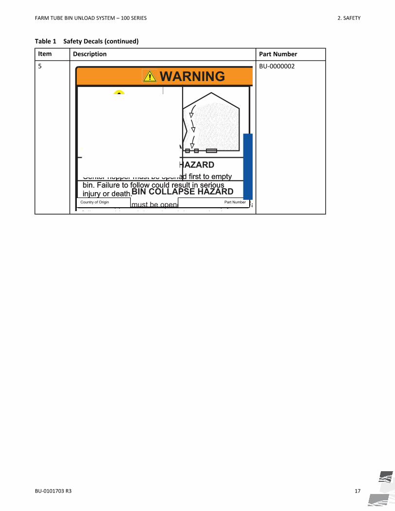
Table 1 Safety Decals (continued)
Item Description Part Number
5
Center hopper must be opened first to empty bin. Failure to follow could result in serious injury or death.
Center hopper must be opened first to empty bin. Failure to follow could result in serious injury or death.
BIN COLLAPSE HAZARD
WARNINGWARNING
BIN COLLAPSE HAZARDCenter hopper must be opened first to empty bin. Failure to follow could result in serious injury or death.
Country of Origin Part Number
BU-0000002
FARM TUBE BIN UNLOAD SYSTEM – 100 SERIES 2. SAFETY

18 BU-0101703 R3
Table 1 Safety Decals (continued)
Item Description Part Number
6
DANGER
ROTATING FLIGHTING HAZARDTo prevent death or serious injury:
• KEEP AWAY from rotating auger flighting.
• DO NOT remove or modify auger flighting guards, doors, or covers. Keep in good working order. Have replaced if damaged.
• DO NOT operate the auger without all guards, doors, and covers in place.
• NEVER touch the auger flighting. Use a stick or other tool to remove an obstruction or clean out.
• Shut off and lock out power to adjust, service, or clean.
To prevent death or serious injury:• KEEP AWAY from rotating auger flighting.
• DO NOT remove or modify auger flighting guards, doors, or covers. Keep in good working order. Have replaced if damaged.
• DO NOT operate the auger without all guards, doors, and covers in place.
• NEVER touch the auger flighting. Use a stick or other tool to remove an obstruction or clean out.
• Shut off and lock out power to adjust, service, or clean.
ROTATING FLIGHTING HAZARD
DANGER
Country of Origin Part Number
20813
2. SAFETY FARM TUBE BIN UNLOAD SYSTEM – 100 SERIES

BU-0101703 R3 19
Table 1 Safety Decals (continued)
Item Description Part Number
7
WARNING
ENTANGLEMENT HAZARDTo prevent serious injury or death:
• Keep body, hair, and clothing away from rotating pulleys, belts, chains, and sprockets.
• Do not operate with any guard removed or modified. Keep guards in good working order.
• Shut off and remove key or lock out power source before inspecting or servicing machine.
To prevent serious injury or death:• Keep body, hair, and clothing away from rotating
pulleys, belts, chains, and sprockets.
• Do not operate with any guard removed or modified. Keep guards in good working order.
• Shut off and remove key or lock out power source before inspecting or servicing machine.
ENTANGLEMENT HAZARD
WARNING
Country of Origin Part Number
20804
8
WARNINGMISSING GUARD HAZARDTo prevent serious injury or death, shut off power and reattach guard before operating machine.
To prevent serious injury or death, shut off power and reattach guard before operating machine.
MISSING GUARD HAZARD
WARNING
Country of Origin Part Number
20803
FARM TUBE BIN UNLOAD SYSTEM – 100 SERIES 2. SAFETY

20 BU-0101703 R3
Table 1 Safety Decals (continued)
Item Description Part Number
9
To prevent serious injury or death:
• Read and understand the manual before assembling, operating, or maintaining the equipment.
• Only trained personnel may assemble, operate, or maintain the equipment.
• Children and untrained personnel must be kept outside of the work area.
• Do not modify the equipment. Keep in good working order.
• If the manual, guards, or decals are missing or damaged, contact factory or dealer for replacements.
• Lock out power before performing maintenance.
WARNINGBU-0020807
2. SAFETY FARM TUBE BIN UNLOAD SYSTEM – 100 SERIES

BU-0101703 R3 21
3. FeaturesBelow are some of the main features of the Westfield Farm Tube Bin Unload System.
Figure 4. Typical Bin Unload System
Table 2. Features
Item Description Item Description
1 Electric Powerhead 8 Bin Unload Controls(for sump gates and sweep gearboxengagement)
2 Center Sump (Center Hopper) 9 Bin Adapter
3 Underfloor Auger 10 Bin Wall
4 Discharge Options:Horizontal (A), Incline (B)
11 Lower Gearbox
5 Bin Sweep 12 Upper Gearbox
6 Intermediate Sump(Intermediate Hopper)
13 Sweep Drive(includes gearbox and wheel)
7 Emergency Sump (E-Sump)
6
5
8
1
11
12
2
7
3
13
9
10
4A
6
5
8
1
11
12
2
7
3
13
9
10
4A4B4B
FARM TUBE BIN UNLOAD SYSTEM – 100 SERIES 3. FEATURES

22 BU-0101703 R3
4. OperationBefore continuing, ensure you have completely read and understood this manual’sSafety section, in addition to the safety information in the section(s) below.
4.1. Operation Safety
• Keep away from rotating and moving parts, including the auger flighting, drive components,shafts, and bearings.
• Do not enter the grain bin while the bin unload is operating.
• Always operate with guards, covers, and shields in place.
• Have another trained person nearby who can shut down the equipment in case of accident.
• Keep the work area clear of bystanders.
• Keep the work area clean and free of debris.
• Ensure maintenance has been performed and is up to date.Refer to your bin operation manual for specific operating and safety information for your bin.
4.2. OverviewThe bin unload system operates by first opening the center sump to remove 70-80% of grain by gravity. Next,the intermediate sumps are opened when the center sump runs empty to free the sweep. Lastly, the bin sweepis operated to remove the remaining 20-30% of grain.
Refer to Figure 5 on page 22To prevent serious injury or death from bin collapse, the centerhopper must be open first to empty bin.
Figure 5. Grain Bin Overall Emptying Procedure
4. OPERATION FARM TUBE BIN UNLOAD SYSTEM – 100 SERIES

BU-0101703 R3 23
4.3. Before Filling the Bin with GrainFollowing this list will prevent problems that may otherwise occur during the unloading process.
1. Check for damage or unusual wear, especially on flighting and bearings.
2. Make sure there are no obstructions in the following locations:
• sweep path along the bin floor bin sweep and underfloor auger flighting
• center or intermediate sumps
3. Prior to filling the bin each time, run the bin unload system to check for proper operation.
4. Close the center sump gate and intermediate sump gates.
5. Park the sweep in the “start/park position” slightly behind intermediate sumps prior to filling the bin eachtime.
Failure to park the sweep in the “start/park position” could result in damage to the sweep,under-floor conveyance system, and/or aeration floor.
4.4. Operating ControlsFigure 6. Bin Unload System Controls
4
1
3
2
5
4
1
3
2
5
FARM TUBE BIN UNLOAD SYSTEM – 100 SERIES 4. OPERATION

24 BU-0101703 R3
Table 3. Bin Unload System Controls
Item Description Operation
1 Gate Control Handle Place on Center Sump Control or Intermediate Sumps Control
2 Center Sump Control Turn clockwise to open center sump or counter-clockwise toclose center sump.
3 Intermediate Sumps Control Turn counter-clockwise to open intermediate sumps orclockwise to close intermediate sumps.
4 Bin Sweep Engage Lever Pull away from bin wall to engage. Push toward bin wall todisengage. Lock into place in both positions.
5 Emergency Sump Control (Optional) Push toward bin wall to open. Pull away from bin wall to close.
4.5. Operation of the Bin Unload SystemPerform the following sections, in order, to fully unload the grain bin.
Unload Grain From the Center Sump1. Disengage the bin sweep gearbox (push gearbox shift handle towards bin wall to disengage bin sweep).
2. Close all sump gates (center, emergency-sump (if equipped), and intermediate sumps).
3. Start system.
NoteWhen starting for the first time, the flighting may run rough until the underfloor auger is polished.
4. Open the center sump slightly. Ensure that grain flows out of the discharge end at a constant rate.
5. Continue to open the center sump and watch for constant product flow at discharge. Do this until centersump is fully open.
6. For the first 30 minutes, check that the underfloor auger flighting functions without excessive vibration.Once the grain mass has been fully drawn down, you are now ready to proceed with unloading grain fromthe intermediate sumps.
Unload Grain From the Intermediate Sumps1. When grain flow from the center sump stops flowing from the discharge, open intermediate sump(s)
halfway.
2. Monitor grain flow for consistency before opening intermediate sump(s) any further.
3. After grain has stopped flowing into intermediate sump(s), shut down and lock out all power to the binunload system. Close all intermediate sump gates.
You are now ready to proceed with unloading grain with the bin sweep.
Unload Grain with the Bin SweepTo prevent damage, do not operate the bin sweep until it is fully exposed.
1. Shut down and lockout all power to the bin unload system.
4. OPERATION FARM TUBE BIN UNLOAD SYSTEM – 100 SERIES

BU-0101703 R3 25
To prevent damage to the unload system, do not engage the binsweep while underfloorauger is operating.
2. Release the locking pin and engage the bin sweep (by shifting the lever away from bin wall). Lock the shiftlever into place.
3. Start the bin unload system.
4. Make sure the center sump is fully open, and maintain a constant grain flow.
5. When grain flow stops and the bin is clean, allow the bin sweep to travel around the bin so that it lines upnext to the intermediate sumps.
Failure to park the bin sweep in the “start/park position” could result in damage to the binsweep, underfloor auger, and/or aeration floor.
4.6. Emergency ShutdownIn an emergency situation:
1. Stop or shut down the power source immediately and lockout power.
2. Ensure the bin unload components come to a stop before inspecting.
3. Correct the emergency situation before resuming work.
4.7. Emergency Sump
Æ The Emergency Sump is an optional component for the Bin Unload System.
If grain flow slows considerably or stops while unloading from the center sump, it may be blocked with clumpedgrain. Open the emergency sump to allow grain to continue unloading.
NoteThe emergency sump cannot be opened while the center sump is open. Close the center sump beforeusing the emergency sump.
4.8. Restarting with a Full Underfloor AugerWhen the bin unload system is shut down inadvertently or due to an emergency, the system may still be filledwith grain.
1. Lock out power and remove as much of the grain as possible from the bin unload system using a grain vac orother tool.
Do not use your hands, feet, or other similar bodily means.
2. Once obstruction is clear, disengage sweep (if applicable). Remove locking pin, shift lever towards bin wall,and lock into place.
3. Close all intermediate sump gates, center and e-sump (if applicable) gate.
4. It may be necessary to tighten the drive belts slightly to handle the heavier than normal loads.
5. If guards or covers have been opened or removed, close or replace them before restarting the unit.
6. Once the problem is corrected, restart the machine.
FARM TUBE BIN UNLOAD SYSTEM – 100 SERIES 4. OPERATION

26 BU-0101703 R3
Starting under load may result in damage to the bin unload system if grain is not removedas much as possible.
7. Once the bin unload system has been started, you may resume normal operation.
4.9. Cleanup1. Clean out any remaining grain with a grain vac, shovels, and/or brooms.
2. Clean up (remove) all settled dust deposits.Buildup of dust inside the grain bin and around the bin sweep and underfloor auger couldlead to a dust explosion if not removed regularly.
4.10. Relocating the Electric Drive to Another Grain BinThe bin unload system’s electric drive (motor and mount) may be moved between bins using a front end loader.Follow the procedure below to relocate the drive. Do not relocate the electric drive to a bin that requires morepower to operate, refer to Section 7. – Specifications on page 39.
1. Shut down and lock out power the bin unload system.
2. Loosen the nuts (5) to disengage the belts, open the pulley guard (2) and remove the belts from the motorpulley.
3. Attach a strap or chain (minimum 500 lb rated) to the electric motor eyebolt (1) and lift slightly with a frontend loader. Lift only enough to relieve the weight of the electric drive (motor and mount) from thepowerhead.
4. Remove the hairpin (4) and hinge pin (3).
5. Lift the electric drive and move it to another identical bin unload system.
6. Attach the electric drive to the next bin unload system similarly to how it was removed.
7. Set the tension of the belt with the hole positions at (A) and nuts (5), ensuring the mount is level. Refer toMaintenance for belt tensioning instructions.
Table 4. Relocating the Electric Drive
Item Description
1 Electric Motor Eyebolt
2 Pulley Guard
3 Hinge Pin
4 Hairpin
5 Nuts
4. OPERATION FARM TUBE BIN UNLOAD SYSTEM – 100 SERIES

BU-0101703 R3 27
Figure 7. Relocating the Electric Drive
4.11. Extended Shutdown / End of SeasonAfter the season’s use, the bin unload should be thoroughly inspected. Repair or replace any worn or damagedcomponents and complete maintenance as described in 5. Maintenance on page 28 to prevent any unnecessarydowntime at the start of the next season.
1
A
4
2
3
1
A
4
2
3
5
FARM TUBE BIN UNLOAD SYSTEM – 100 SERIES 4. OPERATION

28 BU-0101703 R3
5. MaintenanceBefore continuing, ensure you have completely read and understood this manual’sSafety section, in addition to the safety information in the section(s) below.
5.1. Maintenance Safety
• Keep components in good condition. Follow the maintenance procedures.
• Ensure the service area is clean, dry, and has sufficient lighting.
• Do not modify any components without written authorization from the manufacturer.Modification can be dangerous and result in serious injuries.
• Shut down and lock out power before maintaining equipment.
• After maintenance is complete, replace all guards, service doors, and/or covers.
• Use only genuine Westfield replacement parts or equivalent. Use of unauthorized parts willvoid warranty. If in doubt, contact Westfield or your local dealer.
5.2. Maintenance ScheduleProper maintenance habits mean a longer life, better efficiency, and safer operation. Please follow theMaintenance Schedule below. Keep good records of the hours the bin unload has been operated and themaintenance performed.
Daily:
Section 5.3. – Visually Inspect the Equipment on page 29
Annually:
Section 5.4. – Clean and Wash the Equipment on page 29
Section 5.5. – Check the Gearbox Oil on page 29
As Required:
Section 5.6. – Change the Gearbox Oil on page 30
Section 5.7. – Tension the Drive Belts on page 30
Section 5.8. – Align the Drive Belts on page 32
Section 5.9. – Replace the Drive Belts on page 32
Section 5.10. – Replace the Sweep Drive Wheel on page 32
Section 5.11. – Adjust the Bin Sweep Backboard on page 34
Section 5.12. – Adjust the Bin Sweep Engage Handle on page 35
5. MAINTENANCE FARM TUBE BIN UNLOAD SYSTEM – 100 SERIES

BU-0101703 R3 29
5.3. Visually Inspect the EquipmentCheck the following during a visual inspection:
1. Ensure all guards are in place and in good working order.
2. Examine the bin unload for damage or unusual wear.
3. Check tightness of bolts/nuts, fasteners, and hardware (re-torque if necessary).
4. Be sure all safety decals are in place and are legible.
5. Check that the discharge and intake area are free of obstructions.
6. Inspect all moving or rotating parts to see if anything has become entangled in them. Remove any entangledmaterial.
5.4. Clean and Wash the Equipment1. Clean out excess grain from all areas of the equipment.
2. Wash the unload auger that extends outside of the bin with a water hose or pressure washer until all dirt,mud, debris, or residue is gone.
3. Provide sufficient time for the equipment to dry.
5.5. Check the Gearbox Oil1. Remove access panels at center to expose lower gearbox, Figure 8 on page 30.
2. Remove fill/vent plug to check gearbox oil level. Insert an improvised dipstick (rolled paper or plastic tie)into the oil filler hole to determine the oil level.
3. Note the level and the condition of the oil. Maintain oil level at half full (center of cross shaft) with 90W orequivalent gear oil, adding as necessary or drain and refill if condition is poor.
4. Ensure gearbox is level when checking or refilling.
5. Do not overfill when adding oil.
6. Replace fill/vent plug.
7. Replace access panels when complete.
FARM TUBE BIN UNLOAD SYSTEM – 100 SERIES 5. MAINTENANCE

30 BU-0101703 R3
Figure 8. Gearbox Oil Fill Points
1
1
1
1
5.6. Change the Gearbox OilUse SAE approved 90W or equivalent gear oil.
1. Remove gearbox from the bin unload.
2. Place a pan under the drain plug.
3. Use a wrench and remove the drain plug.
4. Loosen the filler plug so air can enter the gearbox and the oil will drain freely.
5. Allow the oil to drain completely.
6. Replace the drain plug.
7. Add oil until the gearbox is half full (center of cross shaft) and replace filler plug. A flexible funnel may berequired. Gearbox should be level when checking or refilling. Do not overfill.
8. Reinstall the gearbox and guards.
5.7. Tension the Drive Belts1. Remove guard and push on the center of the belt span with a force of approximately 5 lb.
2. The belts will deflect approximately 1” (25 mm) when properly tensioned.
5. MAINTENANCE FARM TUBE BIN UNLOAD SYSTEM – 100 SERIES

BU-0101703 R3 31
Figure 9. Schematic
1 inch(25 mm)
3. Tighten or loosen the drive belts (or idler pulley when equipped) to achieve the proper tension.
ImportantThe drive belt should be just tight enough to not slip on the drive pulley when operating. If the beltis too loose, it will slip, possibly causing a squeaking sound and slowing the belt down. If the belt istoo tight, it will cause excess wear.
4. The belt tension can be adjusted at (1) and (2) in Figure 10 on page 31.
Figure 10. Belt Tension Adjustment Points
5. Reattach and secure guard. Start system to ensure proper operation.
1
2
1
2
FARM TUBE BIN UNLOAD SYSTEM – 100 SERIES 5. MAINTENANCE

32 BU-0101703 R3
5.8. Align the Drive Belts
Æ When equipped:
1. Lay a straight edge across the pulley faces to check the alignment.
2. Use the pulley hub to move the pulley to the required position for alignment.
3. Tighten the hub bolts to secure pulley on the drive shaft.
4. Check the belt tension.
5. Reattach and secure the guard.
5.9. Replace the Drive Belts
Æ When equipped:
1. Fully loosen the drive belts.
2. Remove and replace the old belts.
3. Tighten the drive belts as described in Belt Tension.
4. Align the drive belts as described in Belt Alignment.
5. Reattach and secure the guard.
5.10. Replace the Sweep Drive Wheel1. Remove bolts (2) and lift the shield (1) out to free up the drive wheel.
2. Remove the bolt (3) and flat washer (4) and pull the old drive wheel out.
NoteIf the drive wheel does not come out due to bin wall interference, remove the bolt (5) andlockwasher (6) and turn and push the flighting inward to move the drive wheel away from the walluntil it can be removed.
5. MAINTENANCE FARM TUBE BIN UNLOAD SYSTEM – 100 SERIES

BU-0101703 R3 33
Figure 11. Replacing the Sweep Drive Wheel
11
4
3
2
5
6
FARM TUBE BIN UNLOAD SYSTEM – 100 SERIES 5. MAINTENANCE

34 BU-0101703 R3
5.11. Adjust the Bin Sweep BackboardThe bin sweep backboard should not normally require adjustment. The backboard can be adjusted in caseswhere the bin sweep is leaving grain on the bin floor or if the backboard gets stuck on the bin floor. To adjust,loosen the bolts/nuts (1, 2, 3) as shown in the below figures. Tighten bolts/nuts after adjusting.
Figure 12. Adjusting the Bin Sweep Backboard
11
Figure 13. Adjusting the Bin Sweep Backboard
22
3
5. MAINTENANCE FARM TUBE BIN UNLOAD SYSTEM – 100 SERIES

BU-0101703 R3 35
5.12. Adjust the Bin Sweep Engage HandleThe bin sweep engage handle should not require adjustment, however can be adjusted if bin sweep is notengaging or comes out of gear. Loosen the nuts to adjust the position and tighten when bin sweep engagesnormally. Follow normal operating procedures when testing operation.
Figure 14. Adjusting the Bin Sweep Engage Handle
A
FARM TUBE BIN UNLOAD SYSTEM – 100 SERIES 5. MAINTENANCE

36 BU-0101703 R3
6. TroubleshootingBefore continuing, ensure you have completely read and understood this manual’sSafety section, in addition to the safety information in the section(s) below.Shut down and lock out all power sources before diagnosing any of the causes orattempting any of the solutions below.
In the following section, we have listed some causes and solutions to some of the problems you mayencounter.
If you encounter a problem that is difficult to solve, even after having read through this section, pleasecontact your local dealer or distributor. Before you contact them, please have this operation manualand the serial number from your machine ready.
Problem Cause SolutionGearbox won’t engage. Gearbox shift adjust bolt is not
adjusted correctly.Adjust bolt. Flighting needs tobe turned so that the gears canmesh appropriately.
Gearbox won’t stay engaged. Lock pin not in place.
Gearbox shift adjust bolt is notadjusted correctly.
Obstruction in sweep.
Secure lock pin into place.
Adjust bolt.
Remove obstruction.
Hopper slide gates are difficultto open.
Hopper slide plates aredamaged.
Obstruction in hopper.
Slide gate interference withaeration floor planking.
Control rods are binding(hoppers not level to eachother).
Replace plastic slide plates.
Remove obstruction.
Level intermediate hoppers toeach other.
Level intermediate hoppers toeach other.
Sweep will not function. Underfloor auger not engaginglower gearbox stub.
Shift gearbox is not engaged.
Obstruction in sweep.
Ensure underfloor augerflighting is fully meshing withquick attach coupler on lowergearbox.
Engage it.
Remove obstruction.
Underfloor auger plugs wheninitially starting the sweep.
Intermediate hoppers aren’tclosed.
Obstruction in underfloor auger.
Close intermediate hoppers.
Remove obstruction.
6. TROUBLESHOOTING FARM TUBE BIN UNLOAD SYSTEM – 100 SERIES

BU-0101703 R3 37
Problem Cause SolutionSweep drive wheel doesn’tfunction when sweep isactivated.
Key or pin sheared or missing indrive wheel housing.
Chain isn’t adjusted correctlyinside drive wheel housing.
Replace damaged part.
Adjust chain correctly.
Sweep stops travelling aroundthe bin.
Sweep isn’t adjusted correctlyand is hitting a high spot in theaeration floor.
Sweep drive wheel isn’t fullyfunctioning correctly (chainslipping, key missing etc...)
Obstruction in sweep.
Adjust sweep in 2 places: Drivewheel and upper gearbox plate.
Check to ensure chain isfunctional and that all keys /roll pins are in place.
Remove obstruction.
Sweep drive wheel contacts binwall.
Center hopper not centeredduring installation.
Shorten sweep section to allowit to travel all the way aroundbin.
Poor product flow from sweep. Sweep flighting is not timedcorrectly.
Obstruction in sweep.
Damaged or bent flighting.
Remove bolts, rotate flightingto next set of holes and replacebolts.
Remove obstruction.
Bend flighting back to originalshape. If this doesn’t work,replace flighting.
Underfloor auger is not able tomove the grain that the sweepis dumping into the centerhopper.
Obstruction in center hopper.
Intermediate hoppers are open,flooding the underfloor auger.
Flighting not timed correctly onthe underfloor auger.
Remove obstruction.
Close intermediate hoppers.
Pull out underfloor flighting,ensure that it is timed correctly(flighting must make acontinuous spiral).
Grain is flowing over backboardof sweep.
This is normal, and grain will beswept up on the second pass ofthe sweep
No solution needed. Part ofnormal operation.
Underfloor system stops whenmoving product.
Electric motor belts not tightenough.Electric motor is not largeenough to power entire system.
Obstruction in underfloor auger.
Tighten belts.
Replace electric motor with alarger model.
Remove obstruction.
FARM TUBE BIN UNLOAD SYSTEM – 100 SERIES 6. TROUBLESHOOTING

38 BU-0101703 R3
Problem Cause SolutionSweep will not turn or is noisy. Check flights to ensure they’re
not catching.Cut the flights back so thatthere is a 1/4” (6 mm)clearance from hanger.
Sweep is knocking. Gearbox adjustment incorrect. Check to ensure adjustment iscorrect and is fully engaged.
Belt is moving, motor isrunning, but sweep andunderfloor auger not moving.
Set screws and key ways onpulleys not installed or tooloose.
Disengage system and check setscrews and key ways to ensurethey’re installed and tight.
Sweep engaged, underfloorauger and motor running, butsweep flight and/or uppergearbox not turning.
Under floor gearbox shiftlinkage is out of adjustment.
Sheared bolt and key way ingearbox coupler.
Roll pin and key way in centerwell sheared on the lowergearbox drive stub shaft.
Sheared roll pin in gearboxshaft where it is attached to u-joint at the beginning of thesweep flight (key way may bemissing).
Adjust shift linkages to fullyengage sweep (see SweepOwner’s Manual).
Replace key way and bolts andcheck coupler for cracks.
Replace key way and roll pin.
Replace key way and roll pinand install set screw tighten.
Sweep is making a loud, distinct“squeak” noise.
Center flighting tube rubbing onnylon carrier bushing.
Loosen all 4 bolts on centergearbox and tap hanger bracketwith a hammer to adjust andprovide adequate clearancebetween bushing and centertube.
Sweep engaged and running,but not advancing.
Sweep catching on Tek screws(backboard or gearbox).
Backboard catching on the floor.
Rubber on wheel worn down.
Grain condition wet, hard-packed, moldy.
End wheel gearbox contactingbin wall and/or bolts in bin wall.
Ensure Tek screws are fullyscrewed down.
Ensure backboard clearance is1/4” -1/2” (6 mm - 12 mm).Tighten set screws.
Replace with new rubber drivewheels.Sweep will perform poorly ifgrain is out of condition.
Cut obstructive bolt ends off.Use sweep adjustments.
6. TROUBLESHOOTING FARM TUBE BIN UNLOAD SYSTEM – 100 SERIES

BU-0101703 R3 39
7. Specifications
FARM TUBE BIN UNLOAD SYSTEM – 100 SERIES 7. SPECIFICATIONS

40 BU-0101703 R3
7.1. DimensionsFigure 15. 8” Horizontal Model
7. SPECIFICATIONS FARM TUBE BIN UNLOAD SYSTEM – 100 SERIES

BU-0101703 R3 41
Figure 16. 8” Incline Model
77.5in1969mm
13.6in344mm
65.8in1670mm
14.5in367mm
FARM TUBE BIN UNLOAD SYSTEM – 100 SERIES 7. SPECIFICATIONS

42 BU-0101703 R3
Table 5. 8” Model
Bin Unload Model(Bin Diameter)
Dimension "A"
inches millimeters
24' 175.3 4453
27' 193.3 4910
30' 211.3 5367
33' 229.3 5824
36' 247.3 6281
39' 265.3 6739
42' 283.3 7196
45' 301.3 7653
48' 319.3 8110
54' 355.3 9025
60' 391.3 9939
Underfloor FlightingDiameter (Actual)
Sweep FlightingDiameter (Actual)
7" (178 mm) 6" (152 mm)
Incline Section TubeDiameter
Incline SectionFlighting
Diameter (Actual)
10" (254 mm) 9" (229 mm)
7. SPECIFICATIONS FARM TUBE BIN UNLOAD SYSTEM – 100 SERIES

BU-0101703 R3 43
Figure 17. 10” Horizontal Model
FARM TUBE BIN UNLOAD SYSTEM – 100 SERIES 7. SPECIFICATIONS

44 BU-0101703 R3
Figure 18. 10” Incline Model
80.7in2049mm
10.8in274mm
67.2in1707mm
11.9in303mm
7. SPECIFICATIONS FARM TUBE BIN UNLOAD SYSTEM – 100 SERIES
BU-0101703 R3 45
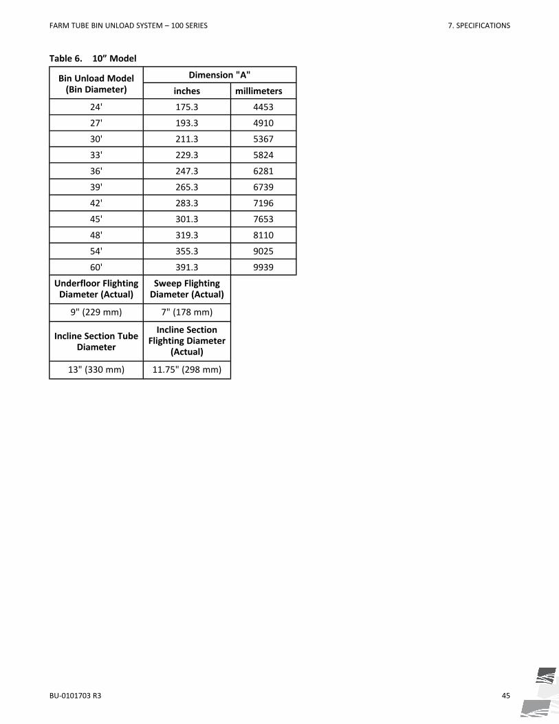
Table 6. 10” Model
Bin Unload Model(Bin Diameter)
Dimension "A"
inches millimeters
24' 175.3 4453
27' 193.3 4910
30' 211.3 5367
33' 229.3 5824
36' 247.3 6281
39' 265.3 6739
42' 283.3 7196
45' 301.3 7653
48' 319.3 8110
54' 355.3 9025
60' 391.3 9939
Underfloor FlightingDiameter (Actual)
Sweep FlightingDiameter (Actual)
9" (229 mm) 7" (178 mm)
Incline Section TubeDiameter
Incline SectionFlighting Diameter
(Actual)
13" (330 mm) 11.75" (298 mm)
FARM TUBE BIN UNLOAD SYSTEM – 100 SERIES 7. SPECIFICATIONS

46 BU-0101703 R3
7.2. Models
7. SPECIFICATIONS FARM TUBE BIN UNLOAD SYSTEM – 100 SERIES

BU-0101703 R3 47
7.3. Power RequirementsTable 7. Electric Motor Requirements
Bin Diameter 8" Tube Unloads (With Sweep) 10" Tube Unloads (With Sweep)
Horizontal(HP)
Incline(HP)
Horizontal(HP)
Incline(HP)
24'
5 7.5
7.5
1027'
10
30'
33'
1536'
7.5
1039'
42'1545'
1048'
2054'15 20
60'
Table 8. Recommended Pulley Size Combinations
Discharge Type UnloadPulley
MotorPulley Pulley Type Belt
SizeFlighting
Speed (rpm)
8" Horizontal 12.7"3.375"
DoubleGroove
B54465
3.875" 534
8" Incline
15"
3.375"
B62
394
3.75" 438
4.75" 554
10" Horizontal
3.375" 394
3.75" 438
4.75" 554
10" Incline 16"
3.375"TripleGroove B67
369
3.75" 410
4.75" 520
Flighting Speed is calculated using a 1750 rpm electric motor. To determine flighting speed (rpm), divide themotor speed (rpm) by the outside diameter of the large unload pulley, then multiply by the outside diameter ofthe small motor pulley. Example: 1750 rpm / 15” x 4-3/4” = 554 rpm.If a slower flighting speed is desired, install a smaller motor pulley.
FARM TUBE BIN UNLOAD SYSTEM – 100 SERIES 7. SPECIFICATIONS

48 BU-0101703 R3
8. Bin Unload Limited WarrantyAg Growth International (“AGI”) warrants all new equipment manufactured by it or one of its divisions, andpurchased from an authorized dealer or distributor, to be free from defects in materials or workmanship for aperiod of two (2) years from the date of original purchase or initial installation (“Warranty Period”).
AGI’s obligation under this warranty is limited to repairing, replacing, or refunding defective part(s) during theWarranty Period. Labor costs associated with the repair of the warrantied equipment are not covered by AGI.Any defects must be reported to AGI before the expiry of the Warranty Period and defective parts identifiedduring the Warranty Period must be returned to the factory, or an authorized AGI dealer or distributor, withtransportation charges prepaid.
Bin Unload systems are designed for use with free flowing, properly conditioned grains and are not warrantedfor use with other substances. Any other use is considered misuse. Malfunctions or failure resulting frommisuse, abuse, negligence, alteration, accident, or lack of proper maintenance shall not be considered defectsunder this warranty. This warranty shall be void if components of the system are not original equipmentsupplied by AGI, or if the equipment has not been assembled, installed, operated, and maintained inaccordance with instructions published by AGI.
The total liability of AGI on any claim, whether in contract, tort or otherwise, arising out of, connected with,or resulting from the manufacture, sale, delivery, repair, replacement or use of the equipment or any partthereof, shall not exceed the price paid for the equipment. AGI shall not be liable for any consequential orspecial damage which any purchaser may suffer or claim to suffer as a result of any defect in the equipment.Consequential or special damages as used herein include, but are not limited to, lost or damaged products orgoods, costs of transportation, lost sales, lost orders, lost income, increased overhead, labor and incidentalcosts and operational inefficiencies.
The warranty provisions herein constitute the full extent of the warranties supplied by AGI for the equipment.Without limiting the generality of the foregoing and to the extent permitted by law, AGI EXPRESSLY DISCLAIMSAND EXCLUDES ALL WARRANTIES AND CONDITIONS OF MERCHANTABILITY & FITNESS FOR PURPOSE ORPERFORMANCE,WHETHER EXPRESS OR IMPLIED, STATUTORY OR OTHERWISE.
Notwithstanding anything contained herein to the contrary, the foregoing sets out the purchaser’s sole andexclusive remedies for breach of warranty by AGI in respect of the equipment.
Dealers are not authorized to make any modifications on behalf of AGI, to any of the terms, conditions orlimitations of this warranty.
AGI reserves the right to change models and specifications at any time without notice or obligation to improveprevious models.
7. SPECIFICATIONS FARM TUBE BIN UNLOAD SYSTEM – 100 SERIES

BU-0101703 R3 49
FARM TUBE BIN UNLOAD SYSTEM – 100 SERIES 7. SPECIFICATIONS
P.O. Box 39Rosenort, Manitoba, R0G 1W0 CanadaPhone: (866) 467-7207 (Canada & USA) or (204) 746–2396Fax: (866) 768-4852
Website: www.grainaugers.comEmail: [email protected]©Ag Growth International Inc. 2017Printed in Canada