Falsework Guide 1988 - Civil · PDF filetabulated loadings. (b) ... safety against lateral...
41
Archive 1 FALSEWORK GUIDE • 1988 SAFETY IN CONSTRUCTION No. 7
-
Upload
phungkhanh -
Category
Documents
-
view
216 -
download
2
Transcript of Falsework Guide 1988 - Civil · PDF filetabulated loadings. (b) ... safety against lateral...

Archive
1
FALSEWORK GUIDE • 1988 SAFETY IN CONSTRUCTION
No. 7

Archive
2
Important Note:
All the publications in the Archive contain the best guidance available at the time of publishing. However, you should consider the effect of any changes to the law since then. You should also check that the Standards referred to are still current.
ISBN-477-03424-1
1st Edition–1982 Revised–1988
Published by the Department of Labour, Wellington, New Zealand.

Archive
3
Contents
Page Introduction ..............................................................................................5
1. Definitions, Scope and General Requirements.................................7
1.1 Definitions ................................................................................7 1.2 Scope ........................................................................................7 1.3 General Requirements ..............................................................8
2. Recommended Safe Construction Practices.....................................9
2.1 General .....................................................................................9 2.2 Materials ...................................................................................9 2.3 Erection ..................................................................................10 2.4 Loading and Dismantling .......................................................19 2.5 Care and Maintenance ............................................................20 2.6 Safety......................................................................................21
3. Guidelines for Temporary Support.................................................22
3.1 Concrete Block Walls.............................................................22 3.2 Tilt-up Precast Concrete Wall Panels.....................................24 3.3 Precast Concrete Flooring ......................................................26
4. Safety Check-list ............................................................................27
4.1 Purpose ...................................................................................27 4.2 General Construction..............................................................27 4.3 Foundations ............................................................................28 4.4 Vertical Supports ....................................................................28 4.5 Horizontal Bearers..................................................................28 4.6 Bracing ...................................................................................29
Appendix A: Some Causes of Accidents & Falsework Failures............30
Appendix B: Summary of Act and Regulations.....................................38
Glossary of Terms ..................................................................................41

Archive
5
Introduction This revised edition of Falsework includes guidelines for the temporary propping of precast concrete floor systems, tilt-up wall panels and concrete block walls. The failure of temporary supports for these structures continues to give cause for much concern. It is essential for the structures to be adequately propped and braced if serious accidents are to be avoided.

Archive
7
1. Definitions, Scope and General Requirements
1.1 DefinitionsFALSE WORK
Means any temporary structure or framework used in construction work to support materials, equipment or any assembly. Falsework includes the use of steel tubes, adjustable steel props, proprietary frames, or any other means to support a permanent structure during its erection and until it becomes self-supporting.
Falsework does not include:
(a) Scaffolding, i.e., structures or frameworks covered by the Department of Labour publi- cation Scaffolding.
(b) Lining, studs, soldiers, walers and internal ties to formwork.
(c) The use of cranes for support.
SCAFFOLDING Means any structure or framework of
a temporary nature, used for the support or protection of workers engaged in construction work, or for the support of materials used in con-nection with such work.
FORMWORK Means the mould into which concrete
is placed.
CONSTRUCTION WORK
Means the erection of building and civil engineering structures such as bridges, viaducts, motorways, towers, silos, chimneys, multi-storey build- ings, single-storey commercial and industrial buildings.
1.2 ScopeFalsework covers a wide range of
temporary support methods: at one end of the scale, props supporting an in situ lintel or inclined members stabilising a precast panel; at the other, complex one-off structures in bridge construction, requiring great skill and experience for their design.
Falsework may be conveniently
divided into two categories: (a) Support for floors and beams
involving light loading and low height of support (within the range of standard props) and capable of solution by standard designs.
(b) All other situations requiring individual designs by persons

Archive
8
competent to do so. The great proportion of structural floors and beams in in situ construction fall, into the first category.
By "standard designs" is meant: (a) Company standard details for
tabulated loadings.
(b) Standard details and tables pro- vided by suppliers of proprietary equipment.
(c) Standard designs given in text- books or relevant codes of practice.
1.3 General Requirements
Falsework should be designed in accordance with sound construction practice, be properly constructed of suitable materials and be maintained in good condition.
The design and supervision of falsework should be carried out by persons who are competent and experienced in this kind of work. Falsework should likewise be erected only by competent and experienced tradespeople.
Construction personnel engaged in the erection of falsework should be adequately informed of the required method of support, and should be provided with drawings or standard design details. (For some jobs, simple sketches may suffice.)
When falsework is notifiable con-struction work, the supervisor should be a safety supervisor in terms of the Construction Act.

Archive
9
2. Recommended Safe Construction Practices
2.1 GeneralFalsework should be constructed
according to the drawings or stan- dard design details. However well falsework is designed, failure can all too easily result if the support system is not erected according to the design/standard details and good practice.
Construction personnel engaged in falsework should ensure that it is erected properly and in a safe and
satisfactory manner. At the same time, other safety aspects as required by the Construction Act 1959 and Construction Regulations 1961 must not be ignored. (See Appendix B.)
Traffic close to, or through, false-work areas should be controlled to ensure that supports are not disturbed until the permanent works have gained sufficient strength to be self-supporting.
2.2 MaterialsMaterials used in falsework should:(a) Be identified correctly and
checked for damage, corrosion or other defects which might affect the strength of the falsework.
(b) Be stored and handled carefully during erection.
Materials that do not conform with the design details should either:
(a) Be approved for use by the false-work designer, or
(b) Be suitably marked and set aside from other falsework materials which are being used.
Proprietary or standard compo-
nents which are damaged or defec- tive should be either repaired or rejected.
Used structural steel members showing excessive corrosion or dam-age should only be used with the supervisor's approval. If in doubt, the supervisor should get the approval of the falsework designer or a registered engineer before using such members.
Falsework materials should com- ply with relevant New Zealand Stan-dards, or other approved standards.
Archive
10
2.3 Erection GENERAL
Since falsework usually consists of a large number of members with a great many connections, it is possible to endanger the whole structure by leaving out either a bolt or a wedge, or by failing to tighten up a connec-tion properly. These small details should therefore be constantly checked during erection. Before load-ing any section of falsework, it should be examined carefully by the super-visor or a person appointed by him. (See also 4.1 Loading.) FOUNDATIONS
Like the columns which support a building, the vertical supports of a falsework structure should be founded on a base sufficiently large and strong enough to carry the loads imposed. Topsoil and weak material at founding levels should be removed and the bearing surface compacted if necessary.
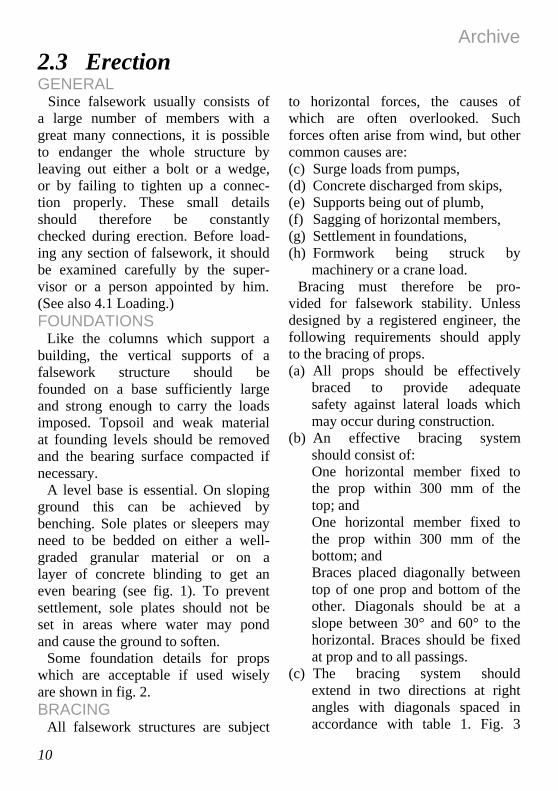
A level base is essential. On sloping ground this can be achieved by benching. Sole plates or sleepers may need to be bedded on either a well-graded granular material or on a layer of concrete blinding to get an even bearing (see fig. 1). To prevent settlement, sole plates should not be set in areas where water may pond and cause the ground to soften.
Some foundation details for props which are acceptable if used wisely are shown in fig. 2. BRACING
All falsework structures are subject
to horizontal forces, the causes of which are often overlooked. Such forces often arise from wind, but other common causes are: (c) Surge loads from pumps, (d) Concrete discharged from skips, (e) Supports being out of plumb, (f) Sagging of horizontal members, (g) Settlement in foundations, (h) Formwork being struck by
machinery or a crane load. Bracing must therefore be pro-
vided for falsework stability. Unless designed by a registered engineer, the following requirements should apply to the bracing of props. (a) All props should be effectively
braced to provide adequate safety against lateral loads which may occur during construction.
(b) An effective bracing system should consist of: One horizontal member fixed to the prop within 300 mm of the top; and One horizontal member fixed to the prop within 300 mm of the bottom; and Braces placed diagonally between top of one prop and bottom of the other. Diagonals should be at a slope between 30° and 60° to the horizontal. Braces should be fixed at prop and to all passings.
(c) The bracing system should extend in two directions at right angles with diagonals spaced in accordance with table 1. Fig. 3

Archive
11
shows typical bracing arrange-ments.
(d) Each row of props should have at least two diagonals, with the same number in each direction (see fig. 3).
(e) Steel tubes of 48 mm outside
diameter and 4.1 mm thickness should be used for bracing adjustable steel props, while tim-ber members of minimum size 100 mm x 50 mm should be used for bracing timber props.
Table 1
SPACING OF DIAGONAL BRACES.
Height of prop m Number of props per diagonal brace
2 2-3 3-4 4-5
4 6 8 12

Archive
12

Archive
13

Archive
14
Archive
15
WORKMANSHIP General requirements:(a) Locate all members and connec-
tions as shown on the design/ standard details.
(b) Install members of the com- pleted falsework within the tolerances specified by the designer.
(c) Tighten all connections such as bolts, screws, jacks and coup-lers, to prevent displacement by vibration or any other cause.
(d) Brace falsework in two directions with horizontal and/or diagonal bracing members.
Specific requirements for standard components:
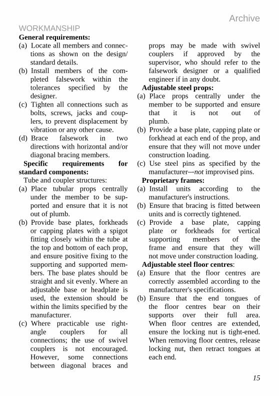
Tube and coupler structures: (a) Place tubular props centrally
under the member to be sup-ported and ensure that it is not out of plumb.
(b) Provide base plates, forkheads or capping plates with a spigot fitting closely within the tube at the top and bottom of each prop, and ensure positive fixing to the supporting and supported mem-bers. The base plates should be straight and sit evenly. Where an adjustable base or headplate is used, the extension should be within the limits specified by the manufacturer.
(c) Where practicable use right-angle couplers for all connections; the use of swivel couplers is not encouraged. However, some connections between diagonal braces and
props may be made with swivel couplers if approved by the supervisor, who should refer to the falsework designer or a qualified engineer if in any doubt.
Adjustable steel props: (a) Place props centrally under the
member to be supported and ensure that it is not out of plumb.
(b) Provide a base plate, capping plate or forkhead at each end of the prop, and ensure that they will not move under construction loading.
(c) Use steel pins as specified by the manufacturer–-not improvised pins.
Proprietary frames: (a) Install units according to the
manufacturer's instructions. (b) Ensure that bracing is fitted between
units and is correctly tightened. (c) Provide a base plate, capping
plate or forkheads for vertical supporting members of the frame and ensure that they will not move under construction loading.
Adjustable steel floor centres: (a) Ensure that the floor centres are
correctly assembled according to the manufacturer's specifications.
(b) Ensure that the end tongues of the floor centres bear on their supports over their full area. When floor centres are extended, ensure the locking nut is tight-ened. When removing floor centres, release locking nut, then retract tongues at each end.

Archive
16
Formwork for combined beam and slab assembly:
(a) Provide sufficient propping. (b) Provide bearers of sufficient
strength to carry loads from the in situ concrete beam and slab.
(c) Ensure that the tongue of the floor centre has full bearing on the top plate.
(d) Ensure that the plates and studs are cut squarely and fit neatly
(e) between the shutter supporting the concrete and the bearer.
(f) Ensure that the tongue of the floor centre is positioned directly over a stud (see fig. 4), or that the plates and their fixings have the strength to carry the floor centre loads to the studs.

Archive
17
Timber beams:
(a) Where required, place beams directly over vertical support members, which should be pro-vided with suitable heads (see fig. 5). Various types of head are available which can be inserted in the tops of vertical supports to support beams. The most com- mon of these are shown in fig. 6. The post head type is provided with holes so that it can be nailed to the timber beams.
(b) Where timber beams support floor centres, it is good practice to place props, where possible, directly under where the floor centre sits on the timber beam, unless the timber beam has the strength to carry the floor centre loads to the props (see fig. 7).
(c) Recommended details for locat- ing timber beams in forkheads are shown in fig. 8.

Archive
18
ADJUSTMENT OF FALSEWORK
General:Falsework should be provided with
suitable means for vertical adjust- ment. Folding wedges and screw jacks may be used for this purpose.
Wedges may be used at the top or the bottom, but not at both ends of a prop.
Archive
19
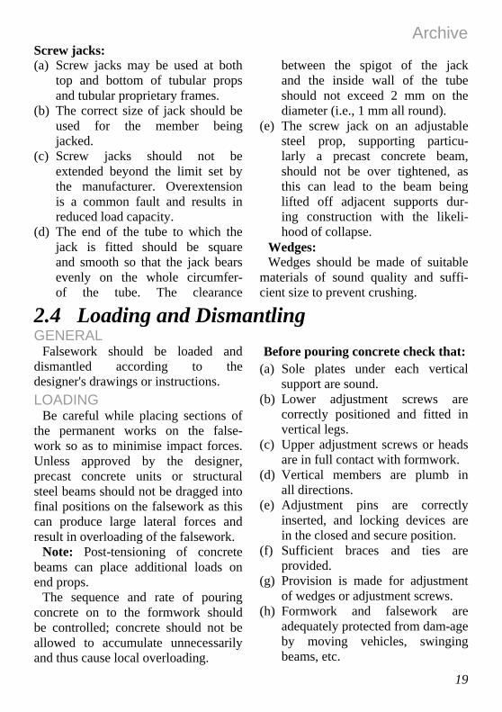
Screw jacks:(a) Screw jacks may be used at both
top and bottom of tubular props and tubular proprietary frames.
(b) The correct size of jack should be used for the member being jacked.
(c) Screw jacks should not be extended beyond the limit set by the manufacturer. Overextension is a common fault and results in reduced load capacity.
(d) The end of the tube to which the jack is fitted should be square and smooth so that the jack bears evenly on the whole circumfer- of the tube. The clearance
between the spigot of the jack and the inside wall of the tube should not exceed 2 mm on the diameter (i.e., 1 mm all round).
(e) The screw jack on an adjustable steel prop, supporting particu- larly a precast concrete beam, should not be over tightened, as this can lead to the beam being lifted off adjacent supports dur- ing construction with the likeli-hood of collapse.
Wedges: Wedges should be made of suitable
materials of sound quality and suffi- cient size to prevent crushing.
2.4 Loading and Dismantling GENERAL
Falsework should be loaded and dismantled according to the designer's drawings or instructions. LOADING
Be careful while placing sections of the permanent works on the false- work so as to minimise impact forces. Unless approved by the designer, precast concrete units or structural steel beams should not be dragged into final positions on the falsework as this can produce large lateral forces and result in overloading of the falsework.
Note: Post-tensioning of concrete beams can place additional loads on end props.
The sequence and rate of pouring concrete on to the formwork should be controlled; concrete should not be allowed to accumulate unnecessarily and thus cause local overloading.
Before pouring concrete check that: (a) Sole plates under each vertical
support are sound. (b) Lower adjustment screws are
correctly positioned and fitted in vertical legs.
(c) Upper adjustment screws or heads are in full contact with formwork.
(d) Vertical members are plumb in all directions.
(e) Adjustment pins are correctly inserted, and locking devices are in the closed and secure position.
(f) Sufficient braces and ties are provided.
(g) Provision is made for adjustment of wedges or adjustment screws.
(h) Formwork and falsework are adequately protected from dam-age by moving vehicles, swinging beams, etc.

Archive
20
(i) Wedges and packing timber are positively fixed.
Frequent checks of the support sys-tem should be carried out during concreting operations. DISMANTLING
Formwork and falsework should be dismantled in a systematic man- ner. This prevents damage to the equipment and facilitates its shifting to the next position. The striking of formwork and removal of falsework under floor slabs are potential hazards. When the falsework supports are lowered and large areas of formwork are to be dropped on to the lowered falsework supports, the supervisor should check that impact loadings do not overstress the falsework.
Sections of the falsework required to remain in position should be clearly indicated to the dismantling crews, preferably by marking.
The following sequence for disman-tling is recommended: (a) Release pressure of vertical sup-
ports in accordance with designer's recommendations.
(b) Remove all bearers or floor cen- tres except those supporting the ends or edges of panels or ply.
(c) As bearers and/or floor centres are removed, place them in their respective stacks.
(d) Remove ply or panels together with bearers and/or floor centres, working progressively from one starting point. As panels or ply are removed, place them in their respective stacks and in corres-ponding sizes if possible.
(e) Removal of vertical supports can then proceed. Carefully place the various types in their respective stacks, i.e., adjustable props in one stack, frames in another, etc.
(f) All nails should be removed from each piece of timber as it is dismantled.
(g) Ensure that clear passages are left around the stacks for access.
(h) Any damaged timber or equip- ment should be removed to pre- vent accidental re-use.
(i) Ensure that stacks of props, etc. are safe.
2.5 Care and MaintenanceBelow are some suggestions to assist
the user or owner of falsework to carry out a planned system of maintenance and repairs, and thus get more service out of the equipment: (a) Straighten and level base plates,
so as to ensure even distribution of load and stability of the verti- cal member during erection.
(b) Paint metal members with rust-
preventive paints, sanding off any rust areas before painting.
(c) Clean and lubricate adjustment threads.
(d) Check welded joints for defects. (e) Clean off cement and concrete
each time a member is disman- tled and before reuse.
(f) Don’t drop or throw members as this causes bending and other defects.

Archive
21
(g) Replace missing or defective parts immediately.
(h) Obtain replacement parts only from the original manufacturer.
(i) Stack floor centres in an upright position, otherwise they may hold water and rust.
(j) Lubricate the inner and outer sections of the floor centre, including the locking nut.
(k) Keep props in a retracted condi-tion when not in use, as most
damage occurs by bending of the inner components when extended.
(l) Don't hit adjustable sections with hammers as dents could prevent extension and retraction of the sections.
(m) Lubricate prop threads. (n) Stack props correctly to avoid
damage or instability of the stack.
2.6 Safety The following are some recommended safety measures:
(a) Make suitable provisions to keep unauthorised persons (or mobile plant) away from the falsework and to safeguard it from acciden- tal impact.
(b) Falsework for structures over any area of public access or over construction roads, should be protected where necessary by a barrier or other means to prevent damage or interference to its soundness.
(c) Supervisors and/or erectors are warned of the. dangers of altering the falsework design, or of pro-
viding additional props, without consulting the falsework designer.
(d) Inspect falsework before and immediately after loading, and particularly after it has been sub-jected to strong winds, extreme temperatures, heavy rain or earthquakes.
(e) Workers should not be employed in the vicinity of or under struc-tures supported by falsework while the pouring of concrete is in progress.
Archive
22
3. Guidelines for Temporary Support
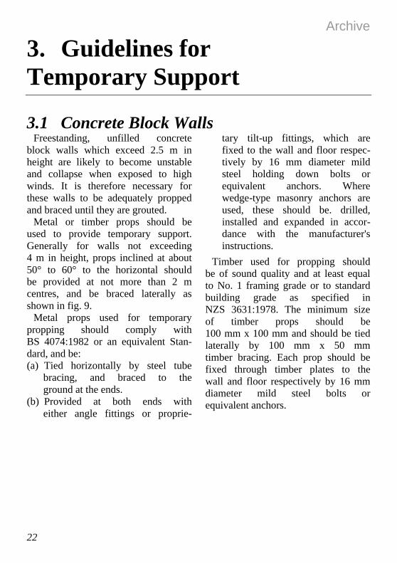
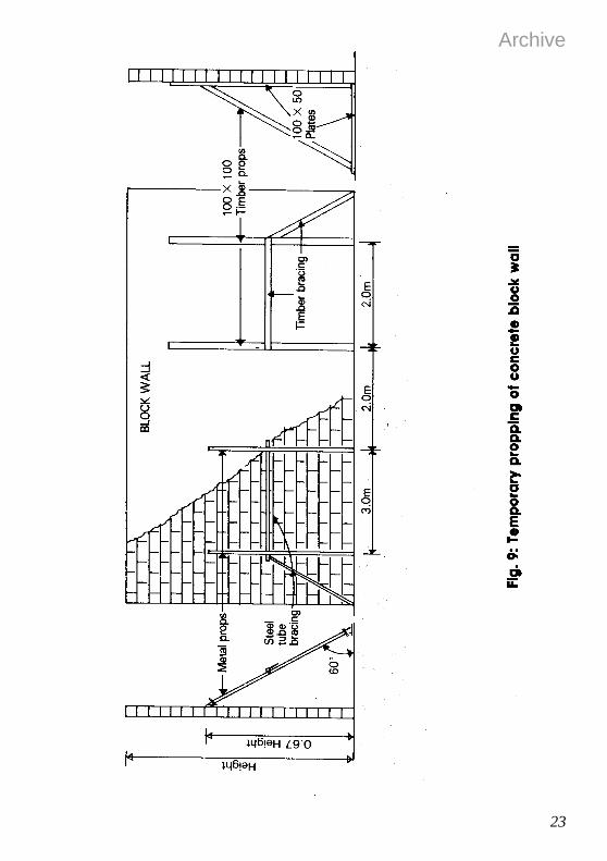
3.1 Concrete Block Walls Freestanding, unfilled concrete
block walls which exceed 2.5 m in height are likely to become unstable and collapse when exposed to high winds. It is therefore necessary for these walls to be adequately propped and braced until they are grouted.
Metal or timber props should be used to provide temporary support. Generally for walls not exceeding 4 m in height, props inclined at about 50° to 60° to the horizontal should be provided at not more than 2 m centres, and be braced laterally as shown in fig. 9.
Metal props used for temporary propping should comply with BS 4074:1982 or an equivalent Stan-dard, and be: (a) Tied horizontally by steel tube
bracing, and braced to the ground at the ends.
(b) Provided at both ends with either angle fittings or proprie-
tary tilt-up fittings, which are fixed to the wall and floor respec-tively by 16 mm diameter mild steel holding down bolts or equivalent anchors. Where wedge-type masonry anchors are used, these should be. drilled, installed and expanded in accor-dance with the manufacturer's instructions.
Timber used for propping should be of sound quality and at least equal to No. 1 framing grade or to standard building grade as specified in NZS 3631:1978. The minimum size of timber props should be 100 mm x 100 mm and should be tied laterally by 100 mm x 50 mm timber bracing. Each prop should be fixed through timber plates to the wall and floor respectively by 16 mm diameter mild steel bolts or equivalent anchors.
Archive
23

Archive
24
3.2 Tilt-up Precast Concrete Wall Panels
Tilt-up panels are also potentially hazardous when exposed to high winds. To ensure stability after erec-tion and before lifting tackle is released, the panels should be tempo-rarily propped and braced until the final fixings to the building structure are completed.
Props should be designed to resist wind forces in accordance with NZS 4203. Unless designed by a reg- istered engineer, the following tem- porary support should be provided: (a) For panels up to 5 m high, use
metal props to BS 4074 or equivalent, as specified in table 2. The props should be fixed and braced laterally as for concrete block walls. Knee bracing should also be provided for panels over 4 m high.
(b) For panels over 5 m high, spe-cially manufactured props of the required length should be used. Standard metal props should not be connected, end to end, to achieve the required length. Lat-eral and knee bracings should also be provided, if necessary. Where proprietary propping sys-tems such as Acrow's 5M shore or Reid's Swiftbrace are used, the manufacturers' recommenda-
tions for fixing, spacing and brac-ing of props must be followed. A propping method for tilt-up panels is illustrated in fig. 10.
Other safety precautions recom-mended are: (c) Panels should be plumb with props
completely installed before released by crane.
(d) Lateral bracing, where required, should be fixed as soon as crane and riggers are clear, and should not be more than one panel behind the last panel erected. Bracing should also be continu-ous, connected at each prop and secured to the end brace.
(e) All members should always be in place and secured at the end of each day.
(f) A minimum of two props should be provided for each panel.
(g) Panels should not be erected dur-ing windy or adverse weather conditions.
(h) Cast inserts for top fixings of props should be a minimum of 300 mm from the edge or any opening in the panel.
(i) Any deviations from manufac-turers' recommendations must be approved by a registered engineer.

Archive
25

Archive
26
3.3 Precast Concrete FlooringTemporary support should be pro-
vided in accordance with the layout shown in the building designer's or manufacturer's working drawings.
The support system should be checked by the building designer or a competent person nominated by the designer, after the floor units are installed and before concrete topping is poured.
Proprietary floor systems which do not require intermediate propping, such as Dyecore, should be propped adjacent to each end support when the beating of the floor units is less than the minimum specified by the manufacturer.
Adjustable steel props for use as temporary support should comply with BS 4074:1982 or to an
equivalent manufacturing standard: the applied loads should not exceed the safe working loads specified in the standard.
The props should be installed at the positions and precamber levels indicated on the working drawings before the floor units are placed.
Each pair of props should be headed with 2 100 mm x 50 mm timber bearers, and supported on 50 mm thick sole plates which are bedded on solid ground or concrete.
The props should be braced in two directions according to the recom-mendation in 2.3 Bracing.
An inspector may require a regis-tered engineer to certify the adequacy of the temporary support.

Archive
27
4. Safety Check-list
4.1 PurposeChecking of falsework should be a
continuous process. Starting with the materials to be used in the founda-tions, there should be regular inspec-tion and checks as each stage of the structure is erected. Leaving such checks until the falsework is com- plete is useless. Errors in materials used, the foundations, and the lower
parts of the structure will be imposs-ible to correct without dismantling. Each level of site supervision should be made fully aware of their responsibilities.
The following safety check-list has been compiled for the guidance of all construction personnel.
4.2 General ConstructionCheck that:(a) Faulty materials are not being
used. (b) Falsework members have been
adequately identified and marked.
(c) Members have been fixed cor- rectly according to drawings or standard details.
(d) Guy ropes or other tension restraints, where required, are correctly angled and tensioned.
(e) No stored materials or spoil are being deposited against the side of the falsework.
(f) Falsework is not being subjected to vibration and shock loads, with the exception of vibrations induced from concrete placing, unless it has been designed to
resist such loads. (g) Unbalanced loads are not acting
on formwork. If observed, the designer should be immediately notified and corrective measures taken.
(h) Formwork and falsework are inspected during and after con-crete placement to detect any abnormal deflection which could lead to failure.
(i) The rate of concrete pour, partic-ularly against formwork for col-umns, is under control.
(j) Props supporting formwork are not being removed prematurely.
(k) Falsework can be dismantled with ease and safety.

Archive
28
4.3 Foundations Check that:(a) Sleepers and sole plates have not
been placed over soft areas or over unsuitable soil.
(b) The ground has not deteriorated due to previous excavations, adjacent drains or pipelines, water softening, erosion, shrinkage, etc.
(c) There are adequate sleepers or sole plates, that they have been set level, and that they have been
adequately bedded and fixed in position.
(d) The benching for foundations on sloping ground is adequate.
(e) There are no signs of settlement, or possible washout after heavy rain and flooding.
(f) There is no crushing of sole plates or cracking of concrete blinding, if applicable.
4.4 Vertical Supports Check that:(a) The correct number and size of
props are being used, and that they are correctly located.
(b) Supports are plumb. (c) Heads of props are centrally
located beneath, and secured to the underside of, supported bearer.
(d) Base plates are securely located over the centre line of the sole plate or sleeper.
(e) Base plates, capping plates or forkheads are not bent.
(f) Screw jacks have not been extended beyond the manufac-turer's recommendation.
(g) Bolts and screw jacks have been
correctly tightened. (h) Correct locking pins are being
used in adjustable steel props. (i) An adjustable prop is not being
placed directly on top of another. (j) Timber props and wedges are of
sound quality and free from defects.
(k) Wedges and ties have been fully secured.
(l) Nailing and splice plates on tim-ber props are adequate.
(m) There is sufficient temporary bracing during erection, and that spacing between supports is as specified.
4.5 Horizontal Bearers Check that:(a) Members are located on the
centre line of supports and are properly fixed in position.
(b) There is no crushing at supports
as a result of inadequate bearing area.
(c) Paired timber members are gauged and secured together with

Archive
29
joints staggered; they should also not vary in depth, otherwise the load will be concentrated on one member.
(d) Adequate washers have been used for bolted timber connections.
(e) There are no signs of buckling in steel beams, and that joints in the beams are located on the centre line of supports.
(f) Joints in paired steel beams are staggered between supports.
4.6 Bracing Check that: (a) All specified members are in
place. (b) All bracings are connected as
close to node points as possible. (c) All bracings are connected to
correct members, e.g. diagonals
to horizontals, to allow right- angle couplers to be used (see fig. 11).
(d) Couplers or bolt connections are properly tightened.
Archive
30
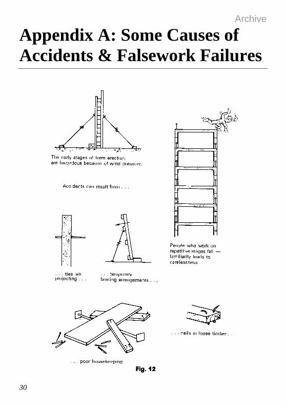
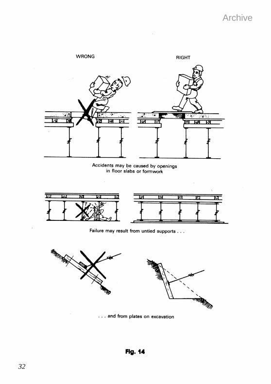
Appendix A: Some Causes of Accidents & Falsework Failures

Archive
31
Archive
32

Archive
33

Archive
34

Archive
35

Archive
36

Archive
37
Archive
38
Appendix B: Summary of Act and Regulations
1. Object of Construction Act 1959 The purpose of the Act is to make better provisions for the safety and welfare of workers engaged in construction work and to advise employers and workers on safe practices.
2. Duties of Construction Safety Inspectors Construction safety inspectors appointed under the Construction Act have as their principal function to promote the safety and welfare of workers engaged in construction work, to advise on safe practices, to investigate accidents, to ensure compliance with the Act and Regulations, and to take such steps as may be desirable to prevent or limit the occurrence or repetition of accidents in construction work. Inspectors are located in most district offices of the Department of Labour, and work under the technical direction of the Chief Construction Safety Engineer in head office. They are Government officers and should not be confused with local body building inspectors or the employers' safety supervisors.
3. Liabilities of Employers The employer is liable for the observance of all requirements, obligations, rules and provisions of the Act and Regulations, and in particular is required to ensure that the work is adequately supervised.
4. Duties and Liabilities of Workers Workers infringe the Act if they disregard wilfully or negligently any lawful instructions by or on behalf of the employer or construction safety inspector issued in accordance with the Act and Regulations, and also if they knowingly do anything liable to endanger themselves or other persons. The actual offender against the Act may be charged with an offence instead of the employer where the inspector is satisfied that the employer was not at fault.

Archive
39
5. Notifiable Works Because they are likely to be dangerous to workers, certain classes of construction work have been declared notifiable construction work. Before any notifiable work is commenced, at least 24 hours’ prior notification must be given to the con-struction safety inspector at the nearest office of the Department of Labour. Forms for this purpose are available from all Department of Labour offices. Information required includes the location and description of the work, the name and address of the employer, the name and certificate number of the safety supervisor, the date of commencement and estimated date of completion. All employers are responsible for ensuring that their section of the work has been notified. Notifiable work is: (a) Any work in which the workers employed risk a fall of 5 m or more; but
not including: Work in connection with a residential building up to and including 2 full storeys; Work on overhead telephone or power lines; Work carried out from a ladder only; Maintenance and repair work of a minor or routine nature.
(b) The construction or use of scaffolding 5 m or more in height. (c) The use of a lifting appliance in any construction work where the appli-
ance has to lift a mass of 500 kg or more a vertical distance of 5 m or more; but not including the use of a self-propelled mobile crane, an excavator, or a forklift.
(d) Any trench, shaft, pit, or other excavation in which workers are required to operate in a restricted space, which is more than 1.5 m deep, and which has a depth greater than the horizontal width at the top.
(e) Any drive, heading, or excavation in which workers are required to work with a ground cover overhead.
(f) Any excavation in which any face has a vertical height of more than 5 m and an average slope steeper than a ratio of 1 horizontal to 2 vertical.
(g) Any work in which explosives are used or in which explosives are kept on the site for the purpose of being used.
(h) Any work in which workers breathe air that is or has been compressed, or a respiratory medium other than air.
(i) Any work which involves the application of asbestos-based materials by spraying.
Note: Construction work that is not notifiable is only exempted from the requirements to notify and to appoint a certificated safety supervisor. It must, however, conform to all other applicable provisions of the Construction Act 1959 and Construction Regulations 1961.

Archive
40
6. Safety Supervisors On notifiable work the employer must appoint an experienced certificated safety supervisor to personally supervise the work. The safety supervisor must remain on the construction site for such periods as are necessary to ensure that the provisions of the Construction Act 1959 and Construction Regulations 1961 are complied with. The name of the safety supervisors must be made known to the workers on the site, and notified to the Department of Labour if the work is notifiable. Where a safety supervisor is replaced for any reason, the construction safety inspector and workers will have to be renotified.
7. Notice of Accidents Notice must be given in writing to the construction safety inspector. This applies where any person is injured or suffers a work-related illness on construction work and is likely to be incapacitated from work for at least 48 hours. It must be notified on form IW 14 incorporating LAB CONST 4, obtainable from any office of the Department of Labour, and must be posted or delivered as soon as practicable and not later than 48 hours after the occurrence. Completing and. posting or delivering the notice is the employer's responsibility. This information is important to the Department as it permits serious or unusual accidents to be investigated without delay. It also provides essential data on the kinds, causes and frequency of accidents, from which a realistic programme of accident prevention in the construction industry can be developed.

Archive
41
Glossary of Terms For the purpose of this guide, the following interpretations of terms used in falsework shall apply:
ADJUSTABLE STEEL FLOOR CENTRE: A telescopic-type member spanning horizontally between supports to carry formwork.
ADJUSTABLE STEEL PROP: An adjustable vertical support member complying with BS 4074.
BASE PLATE: A plate, with or without spigot, fitted to the base of a vertical support member to distribute the vertical load to a sole plate or sleeper.
BLINDING: A layer of plain concrete placed on the ground to form a working surface.
BRACING: A diagonal and horizontal system of structural members which are connected to the vertical, inclined and horizontal members of falsework to provide stability against lateral loads.
BENCHING: Excavation of a sloping ground in horizontal steps.
CAP PLATE: A flat plate, with spigot, provided at the top of a vertical support member.
COUPLER: A device for locking together metal tubes.
DECENTERING: The procedure of progressively removing the floor centres supporting formwork.
FALSE WORK: Any temporary structure or framework used in construction work to support materials, equipment or any assembly.

Archive
42
FORKHEAD: A U-shaped fitting at the top of vertical support members used to locate centres or joists.
FORMWORK: The mould into which concrete is placed.
FOLDING WEDGES: A pair of identical wedges used together as an adjustment device.
FOUNDATIONS: The ground or part of the permanent works resisting the loads from the falsework.
PROP: A vertical or inclined support member of the falsework: the inclined prop is sometimes referred to as a raking shore.
PROP COUPLER: A right-angle coupler used for connecting 48 mm tubes to larger diameter props.
PROPRIETARY FRAMES: A system of falsework constructed from standard components marketed under a trade name.
RIGHT-ANGLE COUPLER: A coupler used for connecting two tubes at right angles, and complying with BS 1139:1982.
SCREW JACK: An adjustment device fitted to the end of a falsework member.
SLEEPER: A member transferring vertical load from more than one vertical support member to the foundation.
SCAFFOLDING: Any structure or framework of a temporary nature, used for the support or protection of workers engaged in construction work, or for the support of materials used in connection with such work.
SOLE PLATE: A member transferring vertical load from one vertical support member to the foundation.

Archive
43
SWIVEL COUPLER: A swivel-type tube fitting used to connect two tubes at any angle where a right-angle coupler cannot be used, complying with BS 1139:1982
TEMPORARY WORKS: All temporary structures constructed at the site, including falsework, formwork, working platforms, access ways and scaffolding.
TUBE: A metal tube complying with the design or standard detail.
TUBE AND COUPLER STRUCTURE: A falsework system in which individual tubes serving as props, bracing, ties etc, are jointed together in the field by means of couplers to form a complete load-carrying structure. All fittings for this system should comply with the design or standard details.


![Safety Management & Site Establishment · e.g. as falsework supporting a formwork system (to be discussed ... Tower scaffolding ... BS 5975[12] defines falsework as ...](https://static.fdocuments.in/doc/165x107/5b0a3b487f8b9ae61b8bc6a4/safety-management-site-as-falsework-supporting-a-formwork-system-to-be-discussed.jpg)