Falk Steelflex Grid Couplings - Home - Rexnord.eu · 2015-03-13 · (421-110M) 3 Falk Steelflex...
44
Grid Coupling Catalog Falk Steelflex Grid Couplings (Metric) Download the most up-to-date versions at www.rexnord.com
-
Upload
phungtuong -
Category
Documents
-
view
238 -
download
1
Transcript of Falk Steelflex Grid Couplings - Home - Rexnord.eu · 2015-03-13 · (421-110M) 3 Falk Steelflex...
Grid Coupling Catalog
Falk Steelflex Grid Couplings(Metric)
Download the most up-to-dateversions at www.rexnord.com
2 (421-110M)
Table Of Contents
DESCRIPTION PAGE
Falk® Steelflex® Grid Coupling Application Guide . . . . . . . . . . . . . . . . . . . . . . . . . . . . . . . . . . . . . . . . . . . . . . . . . . . . . . . . . . . . . . . . . . . . . . . . . . . . . . . . . . . . . . . .3
How to Select . . . . . . . . . . . . . . . . . . . . . . . . . . . . . . . . . . . . . . . . . . . . . . . . . . . . . . . . . . . . . . . . . . . . . . . . . . . . . . . . . . . . . . . . . . . . . . . . . . . . . . . . . . . . . . .4, 5, 6
Quick Selection Method . . . . . . . . . . . . . . . . . . . . . . . . . . . . . . . . . . . . . . . . . . . . . . . . . . . . . . . . . . . . . . . . . . . . . . . . . . . . . . . . . . . . . . . . . . . . . . . . . . . . . . . . . 7, 8
Service Factors . . . . . . . . . . . . . . . . . . . . . . . . . . . . . . . . . . . . . . . . . . . . . . . . . . . . . . . . . . . . . . . . . . . . . . . . . . . . . . . . . . . . . . . . . . . . . . . . . . . . . . . . . . . . . . 9, 10
How to Order . . . . . . . . . . . . . . . . . . . . . . . . . . . . . . . . . . . . . . . . . . . . . . . . . . . . . . . . . . . . . . . . . . . . . . . . . . . . . . . . . . . . . . . . . . . . . . . . . . . . . . . . . . . . . . . . . . 10
Products. . . . . . . . . . . . . . . . . . . . . . . . . . . . . . . . . . . . . . . . . . . . . . . . . . . . . . . . . . . . . . . . . . . . . . . . . . . . . . . . . . . . . . . . . . . . . . . . . . . . . . . . . . . . . . . . . . . . . . 10
CLOSE-COUPLED COUPLINGS
Close-Coupled Type T10 . . . . . . . . . . . . . . . . . . . . . . . . . . . . . . . . . . . . . . . . . . . . . . . . . . . . . . . . . . . . . . . . . . . . . . . . . . . . . . . . . . . . . . . . . . . . . . . . . . . . . . . . . 11
Close-Coupled Type T20 . . . . . . . . . . . . . . . . . . . . . . . . . . . . . . . . . . . . . . . . . . . . . . . . . . . . . . . . . . . . . . . . . . . . . . . . . . . . . . . . . . . . . . . . . . . . . . . . . . . . . . . . . 12
SPACER COUPLINGS
Full Spacer Type T31 . . . . . . . . . . . . . . . . . . . . . . . . . . . . . . . . . . . . . . . . . . . . . . . . . . . . . . . . . . . . . . . . . . . . . . . . . . . . . . . . . . . . . . . . . . . . . . . . . . . . . . . . . 13, 14
Half Spacer Type T35 . . . . . . . . . . . . . . . . . . . . . . . . . . . . . . . . . . . . . . . . . . . . . . . . . . . . . . . . . . . . . . . . . . . . . . . . . . . . . . . . . . . . . . . . . . . . . . . . . . . . . . . . . 15, 16
CONTROLLED TORQUE PRODUCTS
Controlled Torque Types T41, T41-2 . . . . . . . . . . . . . . . . . . . . . . . . . . . . . . . . . . . . . . . . . . . . . . . . . . . . . . . . . . . . . . . . . . . . . . . . . . . . . . . . . . . . . . . . . . . . . . . . 17
Controlled Torque Clutches Types T44 & T44-2 . . . . . . . . . . . . . . . . . . . . . . . . . . . . . . . . . . . . . . . . . . . . . . . . . . . . . . . . . . . . . . . . . . . . . . . . . . . . . . . . . . . . . . . 18
Piloted Controlled Torque Type T45 . . . . . . . . . . . . . . . . . . . . . . . . . . . . . . . . . . . . . . . . . . . . . . . . . . . . . . . . . . . . . . . . . . . . . . . . . . . . . . . . . . . . . . . . . . . . . . . . . 19
Optional Automatic Proximity Sensor Cutout Switch . . . . . . . . . . . . . . . . . . . . . . . . . . . . . . . . . . . . . . . . . . . . . . . . . . . . . . . . . . . . . . . . . . . . . . . . . . . . . . . . . . . . 20
Slip Torque Performance Charts . . . . . . . . . . . . . . . . . . . . . . . . . . . . . . . . . . . . . . . . . . . . . . . . . . . . . . . . . . . . . . . . . . . . . . . . . . . . . . . . . . . . . . . . .21, 22, 23, 24
SPECIALTY COUPLINGS
Floating Shaft Type T50 . . . . . . . . . . . . . . . . . . . . . . . . . . . . . . . . . . . . . . . . . . . . . . . . . . . . . . . . . . . . . . . . . . . . . . . . . . . . . . . . . . . . . . . . . . . . . . . . . . . . . . . 25, 26
Caliper Disc Brake System . . . . . . . . . . . . . . . . . . . . . . . . . . . . . . . . . . . . . . . . . . . . . . . . . . . . . . . . . . . . . . . . . . . . . . . . . . . . . . . . . . . . . . . . . . . . . . . . . . . . . . . . 27
Disc Brake Type T63. . . . . . . . . . . . . . . . . . . . . . . . . . . . . . . . . . . . . . . . . . . . . . . . . . . . . . . . . . . . . . . . . . . . . . . . . . . . . . . . . . . . . . . . . . . . . . . . . . . . . . . . . . 28, 29
High-Speed Type T70 . . . . . . . . . . . . . . . . . . . . . . . . . . . . . . . . . . . . . . . . . . . . . . . . . . . . . . . . . . . . . . . . . . . . . . . . . . . . . . . . . . . . . . . . . . . . . . . . . . . . . . . . . . . 30
Engine Flywheel Adapter Type T90 . . . . . . . . . . . . . . . . . . . . . . . . . . . . . . . . . . . . . . . . . . . . . . . . . . . . . . . . . . . . . . . . . . . . . . . . . . . . . . . . . . . . . . . . . . . . . . . . . . 31
Floating Shaft Type T10/G82 . . . . . . . . . . . . . . . . . . . . . . . . . . . . . . . . . . . . . . . . . . . . . . . . . . . . . . . . . . . . . . . . . . . . . . . . . . . . . . . . . . . . . . . . . . . . . . . . . . . . . . 32
TECHNICAL DATA
Engineering Data . . . . . . . . . . . . . . . . . . . . . . . . . . . . . . . . . . . . . . . . . . . . . . . . . . . . . . . . . . . . . . . . . . . . . . . . . . . . . . . . . . . . . . . . . . . . . . . . . . . . . . . . . . . 33 – 42
Coupling Application Data Sheet . . . . . . . . . . . . . . . . . . . . . . . . . . . . . . . . . . . . . . . . . . . . . . . . . . . . . . . . . . . . . . . . . . . . . . . . . . . . . . . . . . . . . . . . . . . . . . . . . . . 43
(421-110M) 3
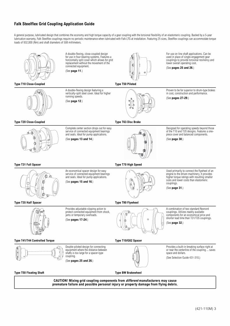
Falk Steelflex Grid Coupling Application Guide
A general purpose, lubricated design that combines the economy and high torque capacity of a gear coupling with the torsional flexibility of an elastomeric coupling. Backed by a 5-year
lubrication warranty, Falk Steelflex couplings require no periodic maintenance when lubricated with Falk LTG at installation. Featuring 25 sizes, Steelflex couplings can accommodate torque
loads of 932,000 (Nm) and shaft diameters of 508 millimeters.
A double-flexing, close-coupled design for use in four-bearing systems. Features a horizontally split cover which allows for grid replacement without the movement of the connected equipment.
(See page 11.)
For use on line shaft applications. Can be used in place of single-engagement gear couplings to provide torsional resiliency and lower overall operating cost.
(See pages 25 and 26.)
Type T10 Close-Coupled Type T50 Piloted
A double-flexing design featuring a vertically-split steel cover. Ideal for higher running speeds.
(See page 12.)
Proven to be far superior to drum-type brakes in cost, construction and performance.
(See pages 27-29.)
Type T20 Close-Coupled Type T63 Disc Brake
Complete center section drops out for easy service of connected equipment bearings and seals. Ideal for pump applications.
(See pages 13 and 14.)
Designed for operating speeds beyond those of the T10 and T20 designs. Features a one-piece cover and balanced components.
(See page 30.)
Type T31 Full Spacer Type T70 High Speed
An economical spacer design for easy service of connected equipment bearings and seals. Ideal for pump applications.
(See pages 15 and 16.)
Used primarily to connect the flywheel of an engine to the driven machinery. It provides higher torque ratings with resulting smaller sizes and lower costs than elastomeric couplings.
(See page 31.)
Type T35 Half Spacer Type T90 Flywheel
Provides adjustable slipping action to protect connected equipment from shock, jams or temporary overloads.
(See pages 17-24.)
A combination of two standard Rexnord couplings. Utilizes readily available components for an economical price and shorter lead time than T31/T35 couplings.
(See page 32.)
Type T41/T44 Controlled Torque Type T10/G82 Spacer
Double-piloted design for connecting equipment where the distance between shafts is too large for a spacer-type coupling.
(See pages 25 and 26.)
Provides a built-in breaking surface right at or near the centerline of the coupling ... saves space and dollars.
(See Selection Guide 431-310.)
Type T50 Floating Shaft Type BW Brakewheel
CAUTION! Mixing grid coupling components from different manufacturers may cause premature failure and possible personal injury or property damage from flying debris.
4 (421-110M)
How to Select
Standard Selection Method (except T41/T44 & T63)
The standard selection method can be used for most motor, turbine or engine-driven
applications. The following information is required to select a flexible coupling:
Horsepower or torque.
Running rpm.
Application or type of equipment to be connected (motor to pump, gear drive to
conveyor, etc.).
Shaft diameters.
Shaft gaps.
Physical space limitations.
Special bore or finish information and type of fit.
Exceptions are High Peak Loads and Brake Applications. For these
conditions use the Formula Selection Method in the next column, or consult
your local Rexnord representative for assistance.
1. Rating: Determine system torque. If torque is not given, calculate as shown below:
System Torque (Nm) = kW x 9549
Rpm
Where horsepower is the actual or transmitted power required by the application (if
unknown, use the motor or turbine nameplate rating) and rpm is the actual speed the
coupling is rotating. Applications that require rapid changes in direction or torque
reversals should be referred to Rexnord Engineering.
2. Service Factor: Determine appropriate service factor from Table 4, page 9.
3. Required Minimum Coupling Rating: Determine the required minimum coupling
rating as shown below:
Minimum Coupling Rating = S.F. (Service Factor) x Torque (Nm)
4. Type: Refer to page 3 and select the appropriate coupling type.
5. Size: Turn to appropriate pages for the coupling type chosen and trace down the
torque column to a value that is equal or greater than that determined in Step 3 above.
The coupling size is shown in the first column.
6. Check: Check speed (rpm), bore, gap and dimensions.
Standard Selection Example:
Select a coupling to connect a 55 kw, 1500 rpm electric motor driving a lobe-type blower.
Motor shaft diameter is 60 mm, blower shaft diameter is 60 mm. Shaft extensions are
140 mm and 110 mm. Selection is replacing a gear-type coupling with a 3 mm gap.
1. Determine Required Rating:
System Torque (Nm) = 55 kW x 9549
= 350 Nm1500 Rpm
2. Service Factor: From Table 4 = 1,25
3. Required Minimum Coupling Rating:
1,25 x 350 Nm = 438 Nm
4. Size: From page 11 a Size 1070T is the proper selection based on a torque rating
of 904 Nm exceeding the required minimum coupling rating of 438 Nm.
5. Check: Allowable speed capacity of 4125 (T10) exceeds the required speed of
1500 rpm. Maximum bore capacity of 67 mm exceeds the actual shaft diameters.
Type T63 Static (Holding) Brake Applications
1. Size: The brake rating must equal or exceed the application requirements. Determine
the required coupling size by comparing the application loads (from Steps A and B
below) to the coupling brake rating listed on page 28. Use the highest torque
value calculated to determine the coupling size.
A. For normal service applications, use the application torque in Nm.
System Torque (Nm) = Transmitted kW x 9549
Rpm
B. For repetitive high peak load applications, use the system peak torque in Nm.
(Repetitive is defined as more than 1000 times during the expected coupling life.)
2. Caliper Torque Brake Rating: For the coupling size selected, compare the
caliper brake torque rating on page 28 to the holding torque requirement of the
application. Rexnord recommends that the caliper torque rating (min.) be at least two
times the holding torque requirement for static applications to compensate for the
possibility of foreign matter on the disc surfaces, loss of condition of the brake pad
surfaces, or other conditions that may affect the holding ability of the caliper brake.
Caliper brakes and brake discs listed are designed primarily for static and/or
emergency brake applications. NOTE: Check brake system and lining wear after
emergency stops. They can, however, also be used for dynamic stopping if only
used occasionally, such as shutting down the equipment for the day or between shift
changes. For stopping high-inertia systems or for applications that require more
frequent stopping, consult your local Rexnord representative.
3. Check: Check maximum bores, speeds and dimensions.
Type T63 Stopping or Service Brake Applications
1. Size: The coupling brake rating must equal or exceed the application requirements.
Determine the required coupling size by comparing the application loads (from Steps
A, B and C below) to the coupling brake rating listed on page 28. Use the highest
torque value calculated to determine the coupling size.
A. For the selected caliper brake and disc diameter, use the maximum brake torque
in Nm.
B. For normal service applications, use the application torque in Nm.
System Torque (Nm) = Transmitted kW x 9549
Rpm
C. For repetitive high peak load applications, use the system peak torque in Nm.
(Repetitive is defined as more than 1000 times during the expected coupling life.)
2. Check: Check maximum bores, speeds and dimensions.
(421-110M) 5
How to Select
Formula Selection Method (except T41/T44 & T63)
The Standard Selection Method can be used for most coupling selections.
The procedures below should be used for:
High Peak Loads.
Brake Applications (where the brake disc or brake wheel is to be an integral part of
the coupling, consult the Factory for design options).
Providing system peak torque and frequency, duty cycle and brake torque rating will
allow for a more refined selection using the Formula Selection Method.
1. High Peak Loads: Use one of the following formulas for applications using motors
with torque characteristics that are higher than normal; applications with intermittent
operations, shock loading, inertia effects due to starting and stopping and/or system-
induced repetitive high peak torques. System Peak Torque is the maximum torque that
can exist in the system. Select a coupling with a torque rating equal to or greater than
selection torque calculated below.
A. Non-Reversing High Peak Torque
Selection Torque (Nm) = System Peak Torque
or
System Torque (Nm) = System Peak kW x 9549
Rpm
B. Reversing High Peak Torque
Selection Torque (Nm) = 2 x System Peak Torque
or
System Torque (Nm) = 2 x Peak kW x 9549
Rpm
C. Occasional Peak Torques (Non-reversing) If a system peak torque occurs less than
1000 times during the expected coupling life, use the following formula:
Selection Torque (Nm) = 0,5 x System Peak Torque
or
System Torque (Nm) = 0,5 x Peak kW x 9549
Rpm
For reversing service select per step B.
2. Brake Applications: If the torque rating of the brake exceeds the motor torque, use
the brake rating as follows:
Selection Torque (Nm) = Brake Torque Rating x S.F.
Formula Selection Example — High Peak Load:
Select a coupling for reversing service to connect a gear drive low-speed shaft to a
runout mill table roll. The electric motor rating is 37 kW at the base speed and the system
peak torque at the coupling is estimated to be 17000 Nm. Coupling speed is 77 rpm at
the motor base speed. The drive shaft diameter is 100 mm with a key of 28 mm x 16 mm.
The runout table roll diameter is 135 mm with a key of 36 mm x 20 mm. Maximum shaft
gap is 180 mm long.
1. Type: Refer to page 3 and select the appropriate coupling type.
2. Required Minimum Coupling Rating:
Use the Reversing High Peak Torque formula in Step 1B.
2 x 17000 = 34000 Nm = Selection Torque
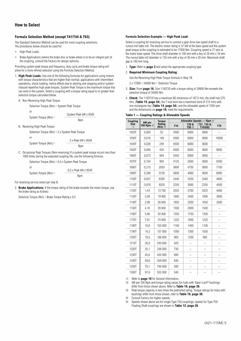
3. Size: From page 16, Size 1150T35 with a torque rating of 39800 Nm exceeds the
selection torque of 34000 Nm.
4. Check: The 1150T35 has a maximum BE dimension of 187,5 mm; the shaft hub 270
mm, (Table 15, page 34); the T hub bore has a maximum bore of 215 mm) with
one rectangular key (Table 14, page 34); and the allowable speed of 1500 rpm
and the dimensions on page 16, meet the requirements.
Table 1 — Coupling Ratings & Allowable Speeds
CouplingSize
kW per 100 Rpm
TorqueRating(Nm)
Allowable Speeds — Rpm
T10T20 & T50
T31, T35 & T10/G82
T70
1020T 0,005 52 4500 6000 3600 –
1030T 0,016 149 4500 6000 3600 10000
1040T 0,026 249 4500 6000 3600 –
1050T 0,046 435 4500 6000 3600 9000
1060T 0,072 684 4350 6000 3600 –
1070T 0,104 994 4125 5500 3600 8200
1080T 0,215 2050 3600 4750 3600 7100
1090T 0,390 3730 3600 4000 3600 6000
1100T 0,657 6280 2440 3250 2440 4900
1110T 0,976 9320 2250 3000 2250 4500
1120T 1,43 13 700 2025 2700 2025 4000
1130T 2,08 19 900 1800 2400 1800 3600
1140T 2,99 28 600 1650 2200 1650 3300
1150T 4,16 39 800 1500 2000 1500 –
1160T 5,86 55 900 1350 1750 1350 –
1170T 7,81 74 600 1225 1600 1225 –
1180T 10,8 103 000 1100 1400 1100 –
1190T 14,3 137 000 1050 1300 1050 –
1200T 19,5 186 000 900 1200 900 –
1210T 26,0 249 000 820 – – –
1220T 35,1 336 000 730 – – –
1230T 45,6 435 000 680 – – –
1240T 58,6 559 000 630 – – –
1250T 78,1 746 000 580 – – –
1260T 97,6 932 000 540 – – –
Refer to page 10 for General Information.
kW per 100 Rpm and torque rating values for hubs with Taper-Lock® bushings
differ from those shown above. Refer to Table 18, page 36.
Peak torque capacity is two times the published rating. Torque ratings for hubs with
bushings differ from those shown, refer to Table 18, page 36.
Consult Factory for higher speeds.
Speeds shown above are for single Type T50 couplings; speeds for Type T50
Floating Shaft couplings are shown in Table 12, page 26.
6 (421-110M)
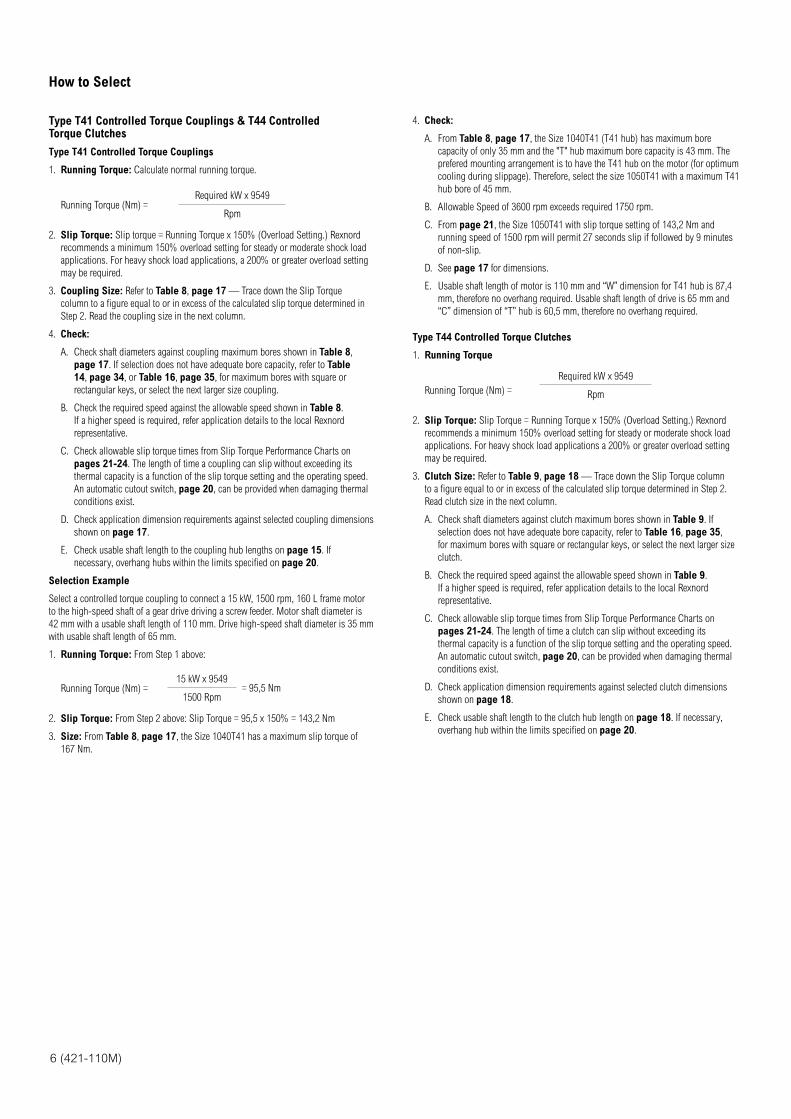
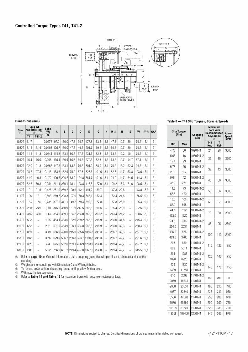
Type T41 Controlled Torque Couplings & T44 Controlled Torque Clutches
Type T41 Controlled Torque Couplings
1. Running Torque: Calculate normal running torque.
Running Torque (Nm) = Required kW x 9549
Rpm
2. Slip Torque: Slip torque = Running Torque x 150% (Overload Setting.) Rexnord
recommends a minimum 150% overload setting for steady or moderate shock load
applications. For heavy shock load applications, a 200% or greater overload setting
may be required.
3. Coupling Size: Refer to Table 8, page 17 — Trace down the Slip Torque
column to a figure equal to or in excess of the calculated slip torque determined in
Step 2. Read the coupling size in the next column.
4. Check:
A. Check shaft diameters against coupling maximum bores shown in Table 8,
page 17. If selection does not have adequate bore capacity, refer to Table
14, page 34, or Table 16, page 35, for maximum bores with square or
rectangular keys, or select the next larger size coupling.
B. Check the required speed against the allowable speed shown in Table 8.
If a higher speed is required, refer application details to the local Rexnord
representative.
C. Check allowable slip torque times from Slip Torque Performance Charts on
pages 21-24. The length of time a coupling can slip without exceeding its
thermal capacity is a function of the slip torque setting and the operating speed.
An automatic cutout switch, page 20, can be provided when damaging thermal
conditions exist.
D. Check application dimension requirements against selected coupling dimensions
shown on page 17.
E. Check usable shaft length to the coupling hub lengths on page 15. If
necessary, overhang hubs within the limits specified on page 20.
Selection Example
Select a controlled torque coupling to connect a 15 kW, 1500 rpm, 160 L frame motor
to the high-speed shaft of a gear drive driving a screw feeder. Motor shaft diameter is
42 mm with a usable shaft length of 110 mm. Drive high-speed shaft diameter is 35 mm
with usable shaft length of 65 mm.
1. Running Torque: From Step 1 above:
Running Torque (Nm) = 15 kW x 9549
= 95,5 Nm1500 Rpm
2. Slip Torque: From Step 2 above: Slip Torque = 95,5 x 150% = 143,2 Nm
3. Size: From Table 8, page 17, the Size 1040T41 has a maximum slip torque of
167 Nm.
4. Check:
A. From Table 8, page 17, the Size 1040T41 (T41 hub) has maximum bore
capacity of only 35 mm and the "T" hub maximum bore capacity is 43 mm. The
prefered mounting arrangement is to have the T41 hub on the motor (for optimum
cooling during slippage). Therefore, select the size 1050T41 with a maximum T41
hub bore of 45 mm.
B. Allowable Speed of 3600 rpm exceeds required 1750 rpm.
C. From page 21, the Size 1050T41 with slip torque setting of 143,2 Nm and
running speed of 1500 rpm will permit 27 seconds slip if followed by 9 minutes
of non-slip.
D. See page 17 for dimensions.
E. Usable shaft length of motor is 110 mm and “W” dimension for T41 hub is 87,4
mm, therefore no overhang required. Usable shaft length of drive is 65 mm and
“C” dimension of “T” hub is 60,5 mm, therefore no overhang required.
Type T44 Controlled Torque Clutches
1. Running Torque
Running Torque (Nm) =
Required kW x 9549
Rpm
2. Slip Torque: Slip Torque = Running Torque x 150% (Overload Setting.) Rexnord
recommends a minimum 150% overload setting for steady or moderate shock load
applications. For heavy shock load applications a 200% or greater overload setting
may be required.
3. Clutch Size: Refer to Table 9, page 18 — Trace down the Slip Torque column
to a figure equal to or in excess of the calculated slip torque determined in Step 2.
Read clutch size in the next column.
A. Check shaft diameters against clutch maximum bores shown in Table 9. If
selection does not have adequate bore capacity, refer to Table 16, page 35,
for maximum bores with square or rectangular keys, or select the next larger size
clutch.
B. Check the required speed against the allowable speed shown in Table 9.
If a higher speed is required, refer application details to the local Rexnord
representative.
C. Check allowable slip torque times from Slip Torque Performance Charts on
pages 21-24. The length of time a clutch can slip without exceeding its
thermal capacity is a function of the slip torque setting and the operating speed.
An automatic cutout switch, page 20, can be provided when damaging thermal
conditions exist.
D. Check application dimension requirements against selected clutch dimensions
shown on page 18.
E. Check usable shaft length to the clutch hub length on page 18. If necessary,
overhang hub within the limits specified on page 20.
How to Select
(421-110M) 7
Quick Selection Method
1. Select Coupling Type.
Refer to page 3 and select the type of coupling to suit your application. If an
application requires a special purpose coupling, refer application details to the local
Rexnord representative.
2. Determine Service Factor.
A. For MOTOR, TURBINE or ENGINE driven applications, refer to Table 4 and
Table 5.
B. For BRAKE or HIGH PEAK LOAD applications, refer to the Formula Selection
Method shown on page 5.
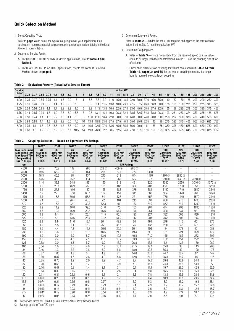
3. Determine Equivalent Power.
Refer to Table 2 — Under the actual kW required and opposite the service factor
determined in Step 2, read the equivalent kW.
4. Determine Coupling Size.
A. Refer to Table 3 — Trace horizontally from the required speed to a kW value
equal to or larger than the kW determined in Step 3. Read the coupling size at top
of column.
B. Check shaft diameters on coupling maximum bores shown in Table 14 thru
Table 17, pages 34 and 35, for the type of coupling selected. If a larger
bore is required, select a larger coupling.
Table 2 — Equivalent Power = (Actual kW x Service Factor)
Service Factor
Actual kW
0.25 0.37 0.55 0.75 1.1 1.5 2.2 3 4 5.5 7.5 9.2 11 15 18.5 22 30 37 45 55 110 132 150 185 200 220 250 300
1.00 0.25 0.37 0.55 0.75 1.1 1.5 2.2 3 4 5.5 7.5 9.2 11.0 15.0 18.5 22.0 30.0 37.0 45.0 55.0 110 132 150 185 200 220 250 300
1.25 0.31 0.46 0.69 0.9 1.4 1.9 2.8 3.8 5 6.9 9.4 11.5 13.8 18.8 23.1 27.5 37.5 46.3 56.3 68.8 138 165 188 231 250 275 313 375
1.50 0.38 0.56 0.83 1.1 1.7 2.3 3.3 4.5 6 8.3 11.3 13.8 16.5 22.5 27.8 33.0 45.0 55.5 67.5 82.5 165 198 225 278 300 330 375 450
1.75 0.44 0.65 0.96 1.3 1.9 2.6 3.9 5.3 7 9.6 13.1 16.1 19.3 26.3 32.4 38.5 52.5 64.8 78.8 96.3 193 231 263 324 350 385 438 525
2.00 0.50 0.74 1.1 1.5 2.2 3.0 4.4 6.0 8 11.0 15.0. 18.4 22.0 30.0 37.0 44.0 60.0 74.0 90.0 110 220 264 300 370 400 440 500 600
2.50 0.63 0.93 1.4 1.9 2.8 3.8 5.5 7.5 10 13.8 18.8 23.0 27.5 37.5 46.3 55.0 75.0 92.5 113 138 275 330 375 463 500 550 625 750
3.00 0.75 1.1 1.7 2.3 3.3 4.5 6.6 9.0 12 16.5 22.5 27.6 33.0 45.0 55.5 66.0 90.0 111 135 165 330 396 450 555 600 660 750 900
3.50 0.88 1.3 1.9 2.6 3.9 5.3 7.7 10.5 14 19.3 26.3 32.2 38.5 52.5 64.8 77.0 105 130 158 193 385 462 525 648 700 770 875 1050
Table 3 — Coupling Selection ... Based on Equivalent kW Ratings
1020T 1030T 1040T 1050T 1060T 1070T 1080T 1090T 1100T 1110T 1120T 1130T
Max Bore (mm)Max Speed T10Max Speed T20
Torque (Nm)kW / 100 rpm
284500 rpm6000 rpm
520,005
354500 rpm6000 rpm
1490,016
434500 rpm6000 rpm
2490,026
504500 rpm6000 rpm
4350,046
564350 rpm6000 rpm
6850,072
674125 rpm5500 rpm
9950,104
803600 rpm4750 rpm
20500,215
953600 rpm4000 rpm
37300,39
1102440 rpm3250 rpm
62750,657
1202250 rpm3000 rpm
93200,976
1402025 rpm2700 rpm
136701,43
1701800 rpm2400 rpm
198852,08
rpm kW Ratings
4500 24.5 70.2 117 205 322 469 966 – – – – –
3600 19.6 56.2 94 164 258 375 773 1410 – – – –
3000 16.3 46.8 78 137 215 313 644 1170 1970 2930 – –
2500 13.6 39.0 65.2 114 179 260 537 977 1650 2440 3580 –
2100 11.4 32.8 54.8 96 150 219 451 820 1380 2050 3010 4370
1800 9.8 28.1 46.9 82 129 188 386 703 1180 1760 2580 3750
1750 9.5 27.3 45.6 80 125 182 376 684 1150 1710 2510 3640
1450 7.9 22.6 37.8 66.1 104 151 311 566 954 1420 2080 3020
1170 6.4 18.3 30.5 53.3 84 122 251 457 770 1140 1670 2440
1000 5.4 15.6 26.1 45.6 72 104 215 391 658 976 1430 2080
870 4.7 13.6 22.7 39.6 62.3 91 187 340 572 849 1250 1810
720 3.9 11.2 18.8 32.8 51.6 75 155 281 474 703 1030 1500
650 3.5 10.1 16.9 29.6 46.5 67.7 140 254 428 634 931 1350
580 3.2 9.1 15.1 26.4 41.5 60.4 125 227 382 566 830 1210
520 2.8 8.1 13.6 23.7 37.2 54.2 112 203 342 508 744 1080
420 2.3 6.6 11.0 19.1 30.1 43.8 90 164 276 410 601 875
350 1.9 5.5 9.1 15.9 25.1 36.5 75 137 230 342 501 729
280 1.5 4.4 7.3 12.8 20.0 29.2 60.1 109 184 273 401 583
230 1.3 3.6 6.0 10.5 16.5 24.0 49.4 90 151 224 329 479
190 1.0 3.0 5.0 8.7 13.6 19.8 40.8 74.2 125 185 272 396
155 0.8 2.4 4.0 7.1 11.1 16.2 33.3 60.5 102 151 222 323
125 0.68 2.0 3.3 5.7 9.0 13.0 26.8 48.8 82 122 179 260
100 0.54 1.6 2.6 4.6 7.2 10.4 21.5 39.1 65.8 98 143 208
84 0.46 1.3 2.2 3.8 6.0 8.8 18.0 32.8 55.3 82 120 175
68 0.37 1.06 1.8 3.1 4.9 7.1 14.6 26.6 44.7 66.4 97 142
56 0.30 0.87 1.5 2.6 4.0 5.8 12.0 21.9 36.8 54.7 80 117
45 0.25 0.70 1.2 2.0 3.2 4.7 9.7 17.6 29.6 43.9 64.4 94
37 0.20 0.58 1.0 1.7 2.6 3.9 7.9 14.5 24.3 36.1 53.0 77
30 0.16 0.47 0.8 1.4 2.1 3.1 6.4 11.7 19.7 29.3 42.9 62.5
25 0.14 0.39 0.65 1.1 1.8 2.6 5.4 9.8 16.5 24.4 35.8 52.1
20 0.11 0.31 0.52 0.91 1.4 2.1 4.3 7.8 13.2 19.5 28.6 41.6
16.5 0.090 0.26 0.43 0.75 1.2 1.7 3.5 6.4 10.9 16.1 23.6 34.4
13.5 0.074 0.21 0.35 0.61 0.97 1.4 2.9 5.3 8.9 13.2 19.3 28.1
11 0.060 0.17 0.29 0.50 0.79 1.1 2.4 4.3 7.2 10.7 15.7 22.9
9 0.049 0.14 0.23 0.41 0.64 0.94 1.9 3.5 5.9 8.8 12.9 18.7
7.5 0.041 0.12 0.20 0.34 0.54 0.78 1.6 2.9 4.9 7.3 10.7 15.6
5 0.027 0.08 0.13 0.23 0.36 0.52 1.1 2.0 3.3 4.9 7.2 10.4
For service factor not listed, Equivalent kW = Actual kW x Service Factor.
Ratings apply to Type T20 only.
8 (421-110M)
Quick Selection Method
C. Check the required speed against the allowable speed shown in Table 1 for the
type of coupling selected. For Type T50 Floating Shaft design, check the allowable
speed from Table 12 on page 26. If a higher speed is required, refer
application details to the local Rexnord representative.
D. Check application dimension requirements against selected coupling type
dimensions shown on pages 11-32.
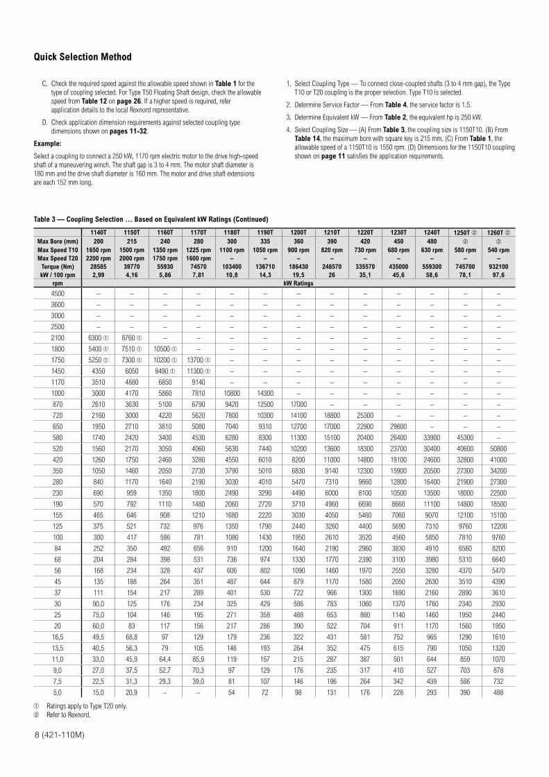
Example:
Select a coupling to connect a 250 kW, 1170 rpm electric motor to the drive high-speed
shaft of a maneuvering winch. The shaft gap is 3 to 4 mm. The motor shaft diameter is
180 mm and the drive shaft diameter is 160 mm. The motor and drive shaft extensions
are each 152 mm long.
1. Select Coupling Type — To connect close-coupled shafts (3 to 4 mm gap), the Type
T10 or T20 coupling is the proper selection. Type T10 is selected.
2. Determine Service Factor — From Table 4, the service factor is 1.5.
3. Determine Equivalent kW — From Table 2, the equivalent hp is 250 kW.
4. Select Coupling Size — (A) From Table 3, the coupling size is 1150T10. (B) From
Table 14, the maximum bore with square key is 215 mm. (C) From Table 1, the
allowable speed of a 1150T10 is 1550 rpm. (D) Dimensions for the 1150T10 coupling
shown on page 11 satisfies the application requirements.
Table 3 — Coupling Selection ... Based on Equivalent kW Ratings (Continued)
1140T 1150T 1160T 1170T 1180T 1190T 1200T 1210T 1220T 1230T 1240T 1250T 1260T
Max Bore (mm) 200 215 240 280 300 335 360 390 420 450 480
Max Speed T10 1650 rpm 1500 rpm 1350 rpm 1225 rpm 1100 rpm 1050 rpm 900 rpm 820 rpm 730 rpm 680 rpm 630 rpm 580 rpm 540 rpm
Max Speed T20 2200 rpm 2000 rpm 1750 rpm 1600 rpm – – – – – – – – –
Torque (Nm) 28585 39770 55930 74570 103400 136710 186430 248570 335570 435000 559300 745700 932100
kW / 100 rpm 2,99 4,16 5,86 7,81 10,8 14,3 19,5 26 35,1 45,6 58,6 78,1 97,6
rpm kW Ratings
4500 – – – – – – – – – – – – –
3600 – – – – – – – – – – – – –
3000 – – – – – – – – – – – – –
2500 – – – – – – – – – – – – –
2100 6300 8760 – – – – – – – – – – –
1800 5400 7510 10500 – – – – – – – – – –
1750 5250 7300 10200 13700 – – – – – – – – –
1450 4350 6050 8490 11300 – – – – – – – – –
1170 3510 4880 6850 9140 – – – – – – – – –
1000 3000 4170 5860 7810 10800 14300 – – – – – – –
870 2610 3630 5100 6790 9420 12500 17000 – – – – – –
720 2160 3000 4220 5620 7800 10300 14100 18800 25300 – – – –
650 1950 2710 3810 5080 7040 9310 12700 17000 22900 29600 – – –
580 1740 2420 3400 4530 6280 8300 11300 15100 20400 26400 33900 45300 –
520 1560 2170 3050 4060 5630 7440 10200 13600 18300 23700 30400 40600 50800
420 1260 1750 2460 3280 4550 6010 8200 11000 14800 19100 24600 32800 41000
350 1050 1460 2050 2730 3790 5010 6830 9140 12300 15900 20500 27300 34200
280 840 1170 1640 2190 3030 4010 5470 7310 9860 12800 16400 21900 27300
230 690 959 1350 1800 2490 3290 4490 6000 8100 10500 13500 18000 22500
190 570 792 1110 1480 2060 2720 3710 4960 6690 8660 11100 14800 18500
155 465 646 908 1210 1680 2220 3030 4050 5460 7060 9070 12100 15100
125 375 521 732 976 1350 1790 2440 3260 4400 5690 7310 9760 12200
100 300 417 586 781 1080 1430 1950 2610 3520 4560 5850 7810 9760
84 252 350 492 656 910 1200 1640 2190 2960 3830 4910 6560 8200
68 204 284 398 531 736 974 1330 1770 2390 3100 3980 5310 6640
56 168 234 328 437 606 802 1090 1460 1970 2550 3280 4370 5470
45 135 188 264 351 487 644 879 1170 1580 2050 2630 3510 4390
37 111 154 217 289 401 530 722 966 1300 1690 2160 2890 3610
30 90,0 125 176 234 325 429 586 783 1060 1370 1760 2340 2930
25 75,0 104 146 195 271 358 488 653 880 1140 1460 1950 2440
20 60,0 83 117 156 217 286 390 522 704 911 1170 1560 1950
16,5 49,5 68,8 97 129 179 236 322 431 581 752 965 1290 1610
13,5 40,5 56,3 79 105 146 193 264 352 475 615 790 1050 1320
11,0 33,0 45,9 64,4 85,9 119 157 215 287 387 501 644 859 1070
9,0 27,0 37,5 52,7 70,3 97 129 176 235 317 410 527 703 878
7,5 22,5 31,3 29,3 39,0 81 107 146 196 264 342 439 586 732
5,0 15,0 20,9 – – 54 72 98 131 176 228 293 390 488
Ratings apply to Type T20 only.
Refer to Rexnord.
(421-110M) 9
Service Factors
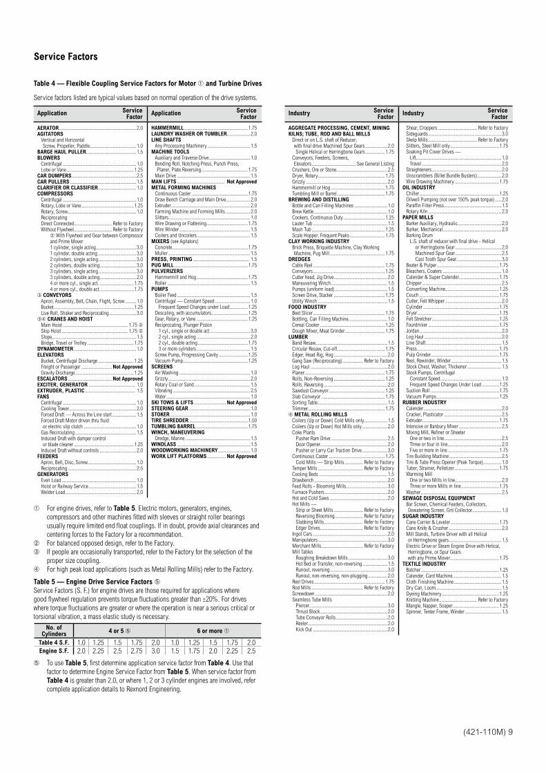
Table 4 — Flexible Coupling Service Factors for Motor and Turbine Drives
Service factors listed are typical values based on normal operation of the drive systems.
Application Service Factor
Application Service Factor
AERATOR ...............................................................2.0AGITATORS
Vertical and Horizontal Screw, Propeller, Paddle ......................................1.0
BARGE HAUL PULLER .........................................1.5BLOWERS
Centrifugal ............................................................1.0Lobe or Vane .......................................................1.25
CAR DUMPERS .....................................................2.5CAR PULLERS ......................................................1.5CLARIFIER OR CLASSIFIER ...............................1.0COMPRESSORS
Centrifugal ............................................................1.0Rotary, Lobe or Vane ...........................................1.25Rotary, Screw ........................................................1.0ReciprocatingDirect Connected............................... Refer to FactoryWithout Flywheel ............................... Refer to Factory
With Flywheel and Gear between Compressor and Prime Mover1 cylinder, single acting .................................3.01 cylinder, double acting ...............................3.02 cylinders, single acting ...............................3.02 cylinders, double acting ..............................3.03 cylinders, single acting ...............................3.03 cylinders, double acting ..............................2.04 or more cyl., single act. ............................1.754 or more cyl., double act. ...........................1.75
CONVEYORSApron, Assembly, Belt, Chain, Flight, Screw .........1.0Bucket .................................................................1.25Live Roll, Shaker and Reciprocating ......................3.0
CRANES AND HOISTMain Hoist ..................................................... 1.75 Skip Hoist ...................................................... 1.75 Slope.....................................................................1.5Bridge, Travel or Trolley ......................................1.75
DYNAMOMETER ...................................................1.0ELEVATORS
Bucket, Centrifugal Discharge .............................1.25Freight or Passenger ......................... Not ApprovedGravity Discharge ................................................1.25
ESCALATORS .................................... Not ApprovedEXCITER, GENERATOR ...................................... 1.0EXTRUDER, PLASTIC ......................................... 1.5FANS
Centrifugal ............................................................1.0Cooling Tower .......................................................2.0Forced Draft — Across the Line start ....................1.5Forced Draft Motor driven thru fluid or electric slip clutch ...........................................1.0
Gas Recirculating ..................................................1.5Induced Draft with damper control or blade cleaner .................................................1.25
Induced Draft without controls ..............................2.0FEEDERS
Apron, Belt, Disc, Screw........................................1.0Reciprocating ........................................................2.5
GENERATORSEven Load .............................................................1.0Hoist or Railway Service .......................................1.5Welder Load ..........................................................2.0
HAMMERMILL ....................................................1.75LAUNDRY WASHER OR TUMBLER ...................2.0LINE SHAFTS
Any Processing Machinery ...................................1.5MACHINE TOOLS
Auxiliary and Traverse Drive ..................................1.0Bending Roll, Notching Press, Punch Press, Planer, Plate Reversing ......................................1.75
Main Drive ............................................................1.5MAN LIFTS ....................................... Not ApprovedMETAL FORMING MACHINES
Continuous Caster ..............................................1.75Draw Bench Carriage and Main Drive....................2.0Extruder.................................................................2.0Farming Machine and Forming Mills ....................2.0Slitters...................................................................1.0Wire Drawing or Flattening..................................1.75Wire Winder ..........................................................1.5Coilers and Uncoilers............................................1.5
MIXERS (see Agitators)Concrete..............................................................1.75Muller ...................................................................1.5
PRESS, PRINTING .............................................. 1.5PUG MILL ............................................................1.75PULVERIZERS
Hammermill and Hog ..........................................1.75Roller ....................................................................1.5
PUMPSBoiler Feed ............................................................1.5Centrifugal — Constant Speed .............................1.0
Frequent Speed Changes under Load ...............1.25Descaling, with accumulators..............................1.25Gear, Rotary, or Vane ..........................................1.25Reciprocating, Plunger Piston
1 cyl., single or double act. ................................3.02 cyl., single acting ............................................2.02 cyl., double acting .........................................1.753 or more cylinders ............................................1.5
Screw Pump, Progressing Cavity ........................1.25Vacuum Pump .....................................................1.25
SCREENSAir Washing ..........................................................1.0Grizzly ...................................................................2.0Rotary Coal or Sand ..............................................1.5Vibrating ...............................................................2.5Water .....................................................................1.0
SKI TOWS & LIFTS .......................... Not ApprovedSTEERING GEAR ..................................................1.0STOKER ..................................................................1.0TIRE SHREDDER ................................................1.50TUMBLING BARREL ..........................................1.75WINCH, MANEUVERING
Dredge, Marine .....................................................1.5WINDLASS ............................................................1.5WOODWORKING MACHINERY ..........................1.0WORK LIFT PLATFORMS ............... Not Approved
For engine drives, refer to Table 5. Electric motors, generators, engines,
compressors and other machines fitted with sleeves or straight roller bearings
usually require limited end float couplings. If in doubt, provide axial clearances and
centering forces to the Factory for a recommendation.
For balanced opposed design, refer to the Factory.
If people are occasionally transported, refer to the Factory for the selection of the
proper size coupling.
For high peak load applications (such as Metal Rolling Mills) refer to the Factory.
Table 5 — Engine Drive Service Factors
Service Factors (S. F.) for engine drives are those required for applications where
good flywheel regulation prevents torque fluctuations greater than ±20%. For drives
where torque fluctuations are greater or where the operation is near a serious critical or
torsional vibration, a mass elastic study is necessary.
No. of Cylinders
4 or 5 6 or more
Table 4 S.F. 1.0 1.25 1.5 1.75 2.0 1.0 1.25 1.5 1.75 2.0Engine S.F. 2.0 2.25 2.5 2.75 3.0 1.5 1.75 2.0 2.25 2.5
To use Table 5, first determine application service factor from Table 4. Use that
factor to determine Engine Service Factor from Table 5. When service factor from
Table 4 is greater than 2.0, or where 1, 2 or 3 cylinder engines are involved, refer
complete application details to Rexnord Engineering.
Industry Service Factor
Industry Service Factor
AGGREGATE PROCESSING, CEMENT, MINING KILNS; TUBE, ROD AND BALL MILLS
Direct or on L.S. shaft of Reducer, with final drive Machined Spur Gears ..................2.0Single Helical or Herringbone Gears ................1.75
Conveyors, Feeders, Screens, Elevators .................................... See General Listing
Crushers, Ore or Stone..........................................2.5Dryer, Rotary .......................................................1.75Grizzly ...................................................................2.0Hammermill or Hog ............................................1.75Tumbling Mill or Barrel .......................................1.75
BREWING AND DISTILLINGBottle and Can Filling Machines ...........................1.0Brew Kettle ............................................................1.0Cookers, Continuous Duty ..................................1.25Lauter Tub .............................................................1.5Mash Tub ............................................................1.25Scale Hopper, Frequent Peaks .............................1.75
CLAY WORKING INDUSTRYBrick Press, Briquette Machine, Clay Working Machine, Pug Mill .............................................1.75
DREDGESCable Reel ...........................................................1.75Conveyors ...........................................................1.25Cutter head, Jig Drive ............................................2.0Maneuvering Winch ..............................................1.5Pumps (uniform load) ...........................................1.5Screen Drive, Stacker ..........................................1.75Utility Winch .........................................................1.5
FOOD INDUSTRYBeet Slicer ...........................................................1.75Bottling, Can Filling Machine ................................1.0Cereal Cooker .....................................................1.25Dough Mixer, Meat Grinder .................................1.75
LUMBERBand Resaw...........................................................1.5Circular Resaw, Cut-off .......................................1.75Edger, Head Rig, Hog ............................................2.0Gang Saw (Reciprocating) ................. Refer to FactoryLog Haul ...............................................................2.0Planer..................................................................1.75Rolls, Non-Reversing ..........................................1.25Rolls, Reversing ....................................................2.0Sawdust Conveyor ..............................................1.25Slab Conveyor ....................................................1.75Sorting Table .........................................................1.5Trimmer...............................................................1.75METAL ROLLING MILLS
Coilers (Up or Down) Cold Mills only ...................1.5Coilers (Up or Down) Hot Mills only .....................2.0Coke Plants
Pusher Ram Drive ..............................................2.5Door Opener.......................................................2.0Pusher or Larry Car Traction Drive .....................3.0
Continuous Caster ..............................................1.75Cold Mills — Strip Mills ............... Refer to Factory
Temper Mills ..................................... Refer to FactoryCooling Beds ........................................................1.5Drawbench ............................................................2.0Feed Rolls - Blooming Mills..................................3.0Furnace Pushers ...................................................2.0Hot and Cold Saws ...............................................2.0Hot Mills —
Strip or Sheet Mills ........................ Refer to FactoryReversing Blooming ....................... Refer to FactorySlabbing Mills ................................ Refer to FactoryEdger Drives ................................... Refer to Factory
Ingot Cars .............................................................2.0Manipulators .........................................................3.0Merchant Mills .................................. Refer to FactoryMill Tables
Roughing Breakdown Mills ................................3.0Hot Bed or Transfer, non-reversing ....................1.5Runout, reversing ...............................................3.0Runout, non-reversing, non-plugging ................2.0
Reel Drives ..........................................................1.75Rod Mills .......................................... Refer to FactoryScrewdown ...........................................................2.0Seamless Tube Mills
Piercer................................................................3.0Thrust Block .......................................................2.0Tube Conveyor Rolls ..........................................2.0Reeler .................................................................2.0Kick Out .............................................................2.0
Shear, Croppers ................................ Refer to FactorySideguards ............................................................3.0Skelp Mills ........................................ Refer to FactorySlitters, Steel Mill only ........................................1.75Soaking Pit Cover Drives —
Lift......................................................................1.0Travel .................................................................2.0
Straighteners .........................................................2.0Unscramblers (Billet Bundle Busters) ....................2.0Wire Drawing Machinery ....................................1.75
OIL INDUSTRYChiller .................................................................1.25Oilwell Pumping (not over 150% peak torque) .....2.0Paraffin Filter Press ...............................................1.5Rotary Kiln ............................................................2.0
PAPER MILLSBarker Auxiliary, Hydraulic ....................................2.0Barker, Mechanical ................................................2.0Barking Drum
L.S. shaft of reducer with final drive - Helicalor Herringbone Gear ......................................2.0Machined Spur Gear ......................................2.5Cast Tooth Spur Gear.....................................3.0
Beater & Pulper ...................................................1.75Bleachers, Coaters ................................................1.0Calender & Super Calender.................................1.75Chipper .................................................................2.5Converting Machine ............................................1.25Couch .................................................................1.75Cutter, Felt Whipper ..............................................2.0Cylinder ..............................................................1.75Dryer ...................................................................1.75Felt Stretcher .......................................................1.25Fourdrinier ..........................................................1.75Jordan ...................................................................2.0Log Haul ...............................................................2.0Line Shaft ..............................................................1.5Press ...................................................................1.75Pulp Grinder........................................................1.75Reel, Rewinder, Winder .........................................1.5Stock Chest, Washer, Thickener ............................1.5Stock Pumps, Centrifugal
Constant Speed ..................................................1.0Frequent Speed Changes Under Load ..............1.25
Suction Roll ........................................................1.75Vacuum Pumps ...................................................1.25
RUBBER INDUSTRYCalender................................................................2.0Cracker, Plasticator ...............................................2.5Extruder...............................................................1.75Intensive or Banbury Mixer ...................................2.5Mixing Mill, Refiner or Sheeter
One or two in line ...............................................2.5Three or four in line ............................................2.0Five or more in line ..........................................1.75
Tire Building Machine ...........................................2.5Tire & Tube Press Opener (Peak Torque) ...............1.0Tuber, Strainer, Pelletizer.....................................1.75Warming Mill
One or two Mills in line ......................................2.0Three or more Mills in line ...............................1.75
Washer ..................................................................2.5SEWAGE DISPOSAL EQUIPMENT
Bar Screen, Chemical Feeders, Collectors, Dewatering Screen, Grit Collector........................1.0
SUGAR INDUSTRYCane Carrier & Leveler ........................................1.75Cane Knife & Crusher ...........................................2.0Mill Stands, Turbine Driver with all Helical or Herringbone gears ...........................................1.5
Electric Drive or Steam Engine Drive with Helical, Herringbone, or Spur Gears with any Prime Mover ........................................1.75
TEXTILE INDUSTRYBatcher ................................................................1.25Calender, Card Machine ........................................1.5Cloth Finishing Machine .......................................1.5Dry Can, Loom......................................................1.5Dyeing Machinery ...............................................1.25Knitting Machine ............................... Refer to FactoryMangle, Napper, Soaper ......................................1.25Spinner, Tenter Frame, Winder ..............................1.5
10 (421-110M)
Service Factors How to Order
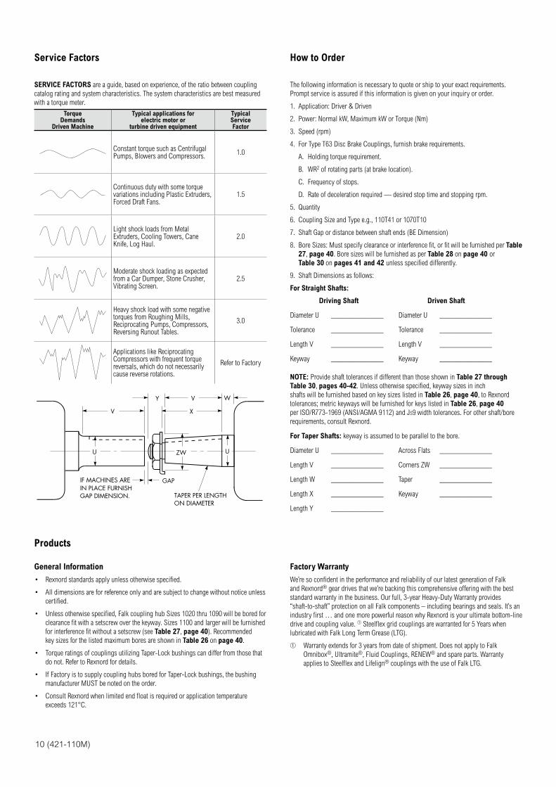
SERVICE FACTORS are a guide, based on experience, of the ratio between coupling
catalog rating and system characteristics. The system characteristics are best measured
with a torque meter.
Torque Demands
Driven Machine
Typical applications for electric motor or
turbine driven equipment
Typical Service Factor
Constant torque such as Centrifugal Pumps, Blowers and Compressors.
1.0
Continuous duty with some torque variations including Plastic Extruders, Forced Draft Fans.
1.5
Light shock loads from Metal Extruders, Cooling Towers, Cane Knife, Log Haul.
2.0
Moderate shock loading as expected from a Car Dumper, Stone Crusher, Vibrating Screen.
2.5
Heavy shock load with some negative torques from Roughing Mills, Reciprocating Pumps, Compressors, Reversing Runout Tables.
3.0
Applications like Reciprocating Compressors with frequent torque reversals, which do not necessarily cause reverse rotations.
Refer to Factory
V
V
Y W
X
U UZW
GAPIF MACHINES AREIN PLACE FURNISHGAP DIMENSION. TAPER PER LENGTH
ON DIAMETER
The following information is necessary to quote or ship to your exact requirements.
Prompt service is assured if this information is given on your inquiry or order.
1. Application: Driver & Driven
2. Power: Normal kW, Maximum kW or Torque (Nm)
3. Speed (rpm)
4. For Type T63 Disc Brake Couplings, furnish brake requirements.
A. Holding torque requirement.
B. WR2 of rotating parts (at brake location).
C. Frequency of stops.
D. Rate of deceleration required — desired stop time and stopping rpm.
5. Quantity
6. Coupling Size and Type e.g., 110T41 or 1070T10
7. Shaft Gap or distance between shaft ends (BE Dimension)
8. Bore Sizes: Must specify clearance or interference fit, or fit will be furnished per Table
27, page 40. Bore sizes will be furnished as per Table 28 on page 40 or
Table 30 on pages 41 and 42 unless specified differently.
9. Shaft Dimensions as follows:
For Straight Shafts:
Driving Shaft Driven Shaft
Diameter U ______________ Diameter U ______________
Tolerance ______________ Tolerance ______________
Length V ______________ Length V ______________
Keyway ______________ Keyway ______________
NOTE: Provide shaft tolerances if different than those shown in Table 27 through
Table 30, pages 40-42. Unless otherwise specified, keyway sizes in inch
shafts will be furnished based on key sizes listed in Table 26, page 40, to Rexnord
tolerances; metric keyways will be furnished for keys listed in Table 26, page 40
per ISO/R773-1969 (ANSI/AGMA 9112) and JS9 width tolerances. For other shaft/bore
requirements, consult Rexnord.
For Taper Shafts: keyway is assumed to be parallel to the bore.
Diameter U ______________ Across Flats ______________
Length V ______________ Corners ZW ______________
Length W ______________ Taper ______________
Length X ______________ Keyway ______________
Length Y ______________
Products
General Information
Rexnord standards apply unless otherwise specified.
All dimensions are for reference only and are subject to change without notice unless
certified.
Unless otherwise specified, Falk coupling hub Sizes 1020 thru 1090 will be bored for
clearance fit with a setscrew over the keyway. Sizes 1100 and larger will be furnished
for interference fit without a setscrew (see Table 27, page 40). Recommended
key sizes for the listed maximum bores are shown in Table 26 on page 40.
Torque ratings of couplings utilizing Taper-Lock bushings can differ from those that
do not. Refer to Rexnord for details.
If Factory is to supply coupling hubs bored for Taper-Lock bushings, the bushing
manufacturer MUST be noted on the order.
Consult Rexnord when limited end float is required or application temperature
exceeds 121°C.
Factory Warranty
We’re so confident in the performance and reliability of our latest generation of Falk
and Rexnord® gear drives that we’re backing this comprehensive offering with the best
standard warranty in the business. Our full, 3-year Heavy-Duty Warranty provides
“shaft-to-shaft” protection on all Falk components – including bearings and seals. It’s an
industry first … and one more powerful reason why Rexnord is your ultimate bottom-line
drive and coupling value. Steelflex grid couplings are warranted for 5 Years when
lubricated with Falk Long Term Grease (LTG).
Warranty extends for 3 years from date of shipment. Does not apply to Falk
Omnibox®, Ultramite®, Fluid Couplings, RENEW® and spare parts. Warranty
applies to Steelflex and Lifelign® couplings with the use of Falk LTG.
NOTE: Dimensions subject to change. Certified dimensions of ordered material furnished on request. (421-110M) 11
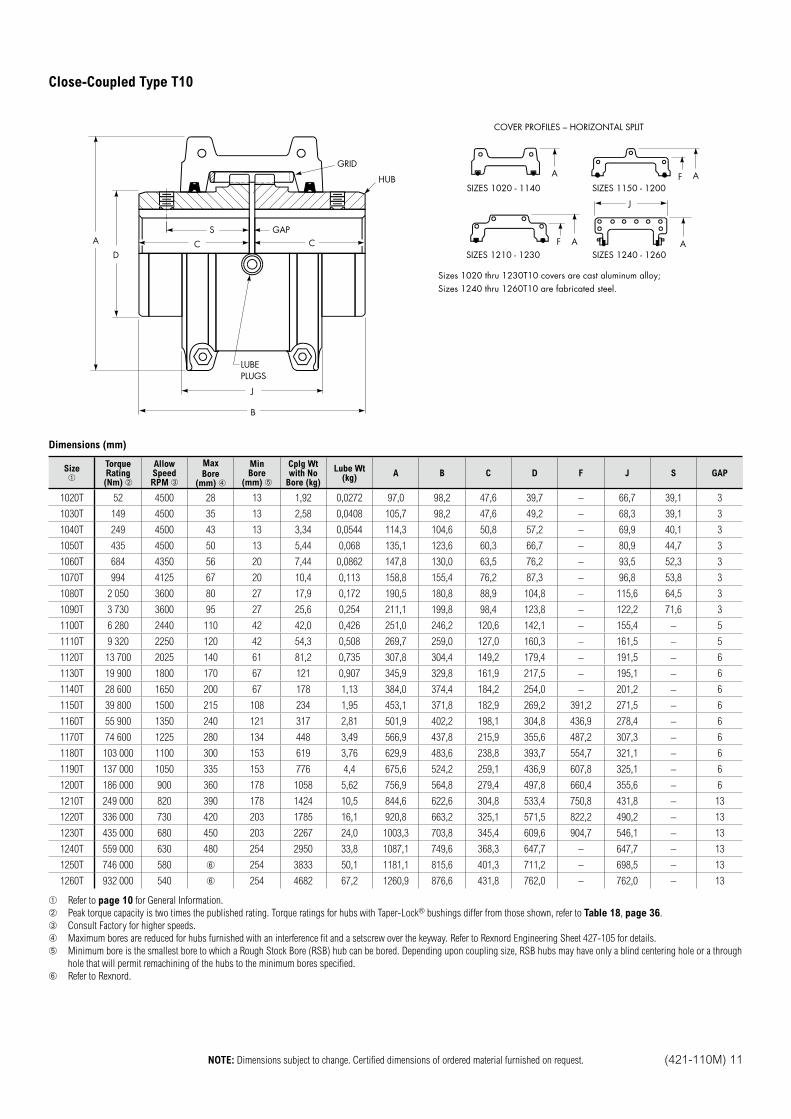
Close-Coupled Type T10
S
C
GAP
GRID
CA
D
LUBEPLUGS
HUB
J
B
A
SIZES 1020 - 1140
SIZES 1210 - 1230
SIZES 1150 - 1200
SIZES 1240 - 1260F A
J
A
AF
COVER PROFILES – HORIZONTAL SPLIT
Sizes 1020 thru 1230T10 covers are cast aluminum alloy; Sizes 1240 thru 1260T10 are fabricated steel.
Dimensions (mm)
Size TorqueRating(Nm)
AllowSpeedRPM
Max
Bore(mm)
MinBore
(mm)
Cplg Wtwith No
Bore (kg)
Lube Wt(kg)
A B C D F J S GAP
1020T 52 4500 28 13 1,92 0,0272 97,0 98,2 47,6 39,7 – 66,7 39,1 3
1030T 149 4500 35 13 2,58 0,0408 105,7 98,2 47,6 49,2 – 68,3 39,1 3
1040T 249 4500 43 13 3,34 0,0544 114,3 104,6 50,8 57,2 – 69,9 40,1 3
1050T 435 4500 50 13 5,44 0,068 135,1 123,6 60,3 66,7 – 80,9 44,7 3
1060T 684 4350 56 20 7,44 0,0862 147,8 130,0 63,5 76,2 – 93,5 52,3 3
1070T 994 4125 67 20 10,4 0,113 158,8 155,4 76,2 87,3 – 96,8 53,8 3
1080T 2 050 3600 80 27 17,9 0,172 190,5 180,8 88,9 104,8 – 115,6 64,5 3
1090T 3 730 3600 95 27 25,6 0,254 211,1 199,8 98,4 123,8 – 122,2 71,6 3
1100T 6 280 2440 110 42 42,0 0,426 251,0 246,2 120,6 142,1 – 155,4 – 5
1110T 9 320 2250 120 42 54,3 0,508 269,7 259,0 127,0 160,3 – 161,5 – 5
1120T 13 700 2025 140 61 81,2 0,735 307,8 304,4 149,2 179,4 – 191,5 – 6
1130T 19 900 1800 170 67 121 0,907 345,9 329,8 161,9 217,5 – 195,1 – 6
1140T 28 600 1650 200 67 178 1,13 384,0 374,4 184,2 254,0 – 201,2 – 6
1150T 39 800 1500 215 108 234 1,95 453,1 371,8 182,9 269,2 391,2 271,5 – 6
1160T 55 900 1350 240 121 317 2,81 501,9 402,2 198,1 304,8 436,9 278,4 – 6
1170T 74 600 1225 280 134 448 3,49 566,9 437,8 215,9 355,6 487,2 307,3 – 6
1180T 103 000 1100 300 153 619 3,76 629,9 483,6 238,8 393,7 554,7 321,1 – 6
1190T 137 000 1050 335 153 776 4,4 675,6 524,2 259,1 436,9 607,8 325,1 – 6
1200T 186 000 900 360 178 1058 5,62 756,9 564,8 279,4 497,8 660,4 355,6 – 6
1210T 249 000 820 390 178 1424 10,5 844,6 622,6 304,8 533,4 750,8 431,8 – 13
1220T 336 000 730 420 203 1785 16,1 920,8 663,2 325,1 571,5 822,2 490,2 – 13
1230T 435 000 680 450 203 2267 24,0 1003,3 703,8 345,4 609,6 904,7 546,1 – 13
1240T 559 000 630 480 254 2950 33,8 1087,1 749,6 368,3 647,7 – 647,7 – 13
1250T 746 000 580 254 3833 50,1 1181,1 815,6 401,3 711,2 – 698,5 – 13
1260T 932 000 540 254 4682 67,2 1260,9 876,6 431,8 762,0 – 762,0 – 13
Refer to page 10 for General Information.
Peak torque capacity is two times the published rating. Torque ratings for hubs with Taper-Lock® bushings differ from those shown, refer to Table 18, page 36.
Consult Factory for higher speeds.
Maximum bores are reduced for hubs furnished with an interference fit and a setscrew over the keyway. Refer to Rexnord Engineering Sheet 427-105 for details.
Minimum bore is the smallest bore to which a Rough Stock Bore (RSB) hub can be bored. Depending upon coupling size, RSB hubs may have only a blind centering hole or a through
hole that will permit remachining of the hubs to the minimum bores specified.
Refer to Rexnord.
Close-Coupled Couplings
12 (421-110M) NOTE: Dimensions subject to change. Certified dimensions of ordered material furnished on request.
GAPS
CC
HH
JJ
B
LUBEPLUGS
GRID
HUB
CLEARANCE FORGRID REMOVAL
M M
A F D
VERTICAL SPLIT COVER
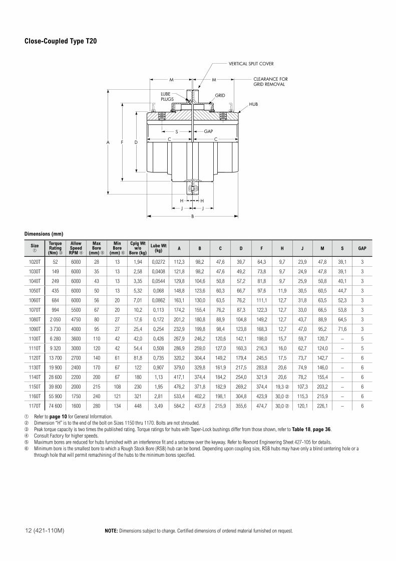
Dimensions (mm)
SizeTorqueRating (Nm)
AllowSpeedRPM
MaxBore
(mm)
MinBore
(mm)
Cplg Wtw/o
Bore (kg)
Lube Wt(kg) A B C D F H J M S GAP
1020T 52 6000 28 13 1,94 0,0272 112,3 98,2 47,6 39,7 64,3 9,7 23,9 47,8 39,1 3
1030T 149 6000 35 13 2,58 0,0408 121,8 98,2 47,6 49,2 73,8 9,7 24,9 47,8 39,1 3
1040T 249 6000 43 13 3,35 0,0544 129,8 104,6 50,8 57,2 81,8 9,7 25,9 50,8 40,1 3
1050T 435 6000 50 13 5,32 0,068 148,8 123,6 60,3 66,7 97,6 11,9 30,5 60,5 44,7 3
1060T 684 6000 56 20 7,01 0,0862 163,1 130,0 63,5 76,2 111,1 12,7 31,8 63,5 52,3 3
1070T 994 5500 67 20 10,2 0,113 174,2 155,4 76,2 87,3 122,3 12,7 33,0 66,5 53,8 3
1080T 2 050 4750 80 27 17,6 0,172 201,2 180,8 88,9 104,8 149,2 12,7 43,7 88,9 64,5 3
1090T 3 730 4000 95 27 25,4 0,254 232,9 199,8 98,4 123,8 168,3 12,7 47,0 95,2 71,6 3
1100T 6 280 3600 110 42 42,0 0,426 267,9 246,2 120,6 142,1 198,0 15,7 59,7 120,7 – 5
1110T 9 320 3000 120 42 54,4 0,508 286,9 259,0 127,0 160,3 216,3 16,0 62,7 124,0 – 5
1120T 13 700 2700 140 61 81,8 0,735 320,2 304,4 149,2 179,4 245,5 17,5 73,7 142,7 – 6
1130T 19 900 2400 170 67 122 0,907 379,0 329,8 161,9 217,5 283,8 20,6 74,9 146,0 – 6
1140T 28 600 2200 200 67 180 1,13 417,1 374,4 184,2 254,0 321,9 20,6 78,2 155,4 – 6
1150T 39 800 2000 215 108 230 1,95 476,2 371,8 182,9 269,2 374,4 19,3 107,3 203,2 – 6
1160T 55 900 1750 240 121 321 2,81 533,4 402,2 198,1 304,8 423,9 30,0 115,3 215,9 – 6
1170T 74 600 1600 280 134 448 3,49 584,2 437,8 215,9 355,6 474,7 30,0 120,1 226,1 – 6
Refer to page 10 for General Information.
Dimension “H” is to the end of the bolt on Sizes 1150 thru 1170. Bolts are not shrouded.
Peak torque capacity is two times the published rating. Torque ratings for hubs with Taper-Lock bushings differ from those shown, refer to Table 18, page 36.
Consult Factory for higher speeds.
Maximum bores are reduced for hubs furnished with an interference fit and a setscrew over the keyway. Refer to Rexnord Engineering Sheet 427-105 for details.
Minimum bore is the smallest bore to which a Rough Stock Bore (RSB) hub can be bored. Depending upon coupling size, RSB hubs may have only a blind centering hole or a
through hole that will permit remachining of the hubs to the minimum bores specified.
Close-Coupled Type T20
NOTE: Dimensions subject to change. Certified dimensions of ordered material furnished on request. (421-110M) 13
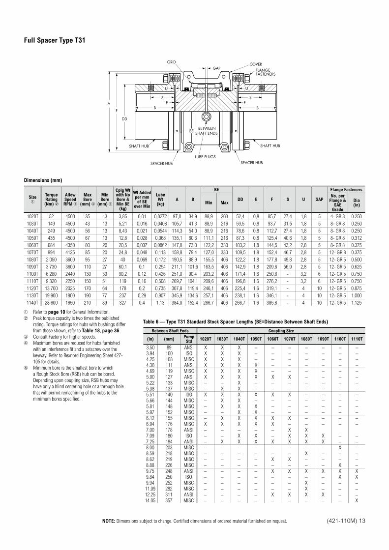
ES
B B
LUBE PLUGSSPACER HUB
SHAFT HUBSHAFT HUB
SEA
F
DD
GRIDGAP
COVERFLANGEFASTENERS
U
BEBETWEEN
SHAFT ENDS
U
SPACER HUB
Dimensions (mm)
Size TorqueRating(Nm)
AllowSpeedRPM
Max Bore
(mm)
MinBore
(mm)
Cplg Wtwith NoBore & Min BE
(kg)
Wt Added per mm of BE
over Min
Lube Wt(kg)
A B
BE
DD E F S U GAP
Flange Fasteners
Min Max
No. perFlange &
SAE Grade
Dia(in)
1020T 52 4500 35 13 3,85 0,01 0,0272 97,0 34,9 88,9 203 52,4 0,8 85,7 27,4 1,8 5 4- GR 8 0.250
1030T 149 4500 43 13 5,21 0,016 0,0408 105,7 41,3 88,9 216 59,5 0,8 93,7 31,5 1,8 5 8- GR 8 0.250
1040T 249 4500 56 13 8,43 0,021 0,0544 114,3 54,0 88,9 216 78,6 0,8 112,7 27,4 1,8 5 8- GR 8 0.250
1050T 435 4500 67 13 12,8 0,028 0,068 135,1 60,3 111,1 216 87,3 0,8 125,4 40,6 1,8 5 8- GR 8 0.312
1060T 684 4350 80 20 20,5 0,037 0,0862 147,8 73,0 122,2 330 103,2 1,8 144,5 43,2 2,8 5 8- GR 8 0.375
1070T 994 4125 85 20 24,8 0,048 0,113 158,8 79,4 127,0 330 109,5 1,8 152,4 46,7 2,8 5 12- GR 8 0.375
1080T 2 050 3600 95 27 40 0,069 0,172 190,5 88,9 155,5 406 122,2 1,8 177,8 49,8 2,8 5 12- GR 5 0.500
1090T 3 730 3600 110 27 60,1 0,1 0,254 211,1 101,6 163,5 406 142,9 1,8 209,6 56,9 2,8 5 12- GR 5 0.625
1100T 6 280 2440 130 39 90,2 0,12 0,426 251,0 90,4 203,2 406 171,4 1,6 250,8 - 3,2 6 12- GR 5 0.750
1110T 9 320 2250 150 51 119 0,16 0,508 269,7 104,1 209,6 406 196,8 1,6 276,2 - 3,2 6 12- GR 5 0.750
1120T 13 700 2025 170 64 178 0,2 0,735 307,8 119,4 246,1 406 225,4 1,6 319,1 - 4 10 12- GR 5 0.875
1130T 19 900 1800 190 77 237 0,29 0,907 345,9 134,6 257,1 406 238,1 1,6 346,1 - 4 10 12- GR 5 1.000
1140T 28 600 1650 210 89 327 0,4 1,13 384,0 152,4 266,7 406 266,7 1,6 385,8 - 4 10 12- GR 5 1.125
Refer to page 10 for General Information.
Peak torque capacity is two times the published
rating. Torque ratings for hubs with bushings differ
from those shown, refer to Table 18, page 36.
Consult Factory for higher speeds.
Maximum bores are reduced for hubs furnished
with an interference fit and a setscrew over the
keyway. Refer to Rexnord Engineering Sheet 427-
105 for details.
Minimum bore is the smallest bore to which
a Rough Stock Bore (RSB) hub can be bored.
Depending upon coupling size, RSB hubs may
have only a blind centering hole or a through hole
that will permit remachining of the hubs to the
minimum bores specified.
Table 6 — Type T31 Standard Stock Spacer Lengths (BE=Distance Between Shaft Ends)
Between Shaft Ends Coupling Size
(in) (mm)Pump Std
1020T 1030T 1040T 1050T 1060T 1070T 1080T 1090T 1100T 1110T
3.50 89 ANSI X X X – – – – – – –
3.94 100 ISO X X X – – – – – – –
4.25 108 MISC X X X – – – – – – –
4.38 111 ANSI X X X X – – – – – –
4.69 119 MISC X X X X – – – – – –
5.00 127 ANSI X X X X X X – – – –
5.22 133 MISC – – X – – – – – – –
5.38 137 MISC – X X – – – – – – –
5.51 140 ISO X X X X X X – – – –
5.66 144 MISC – X X – – – – – – –
5.81 148 MISC – X X X – – – – – –
5.97 152 MISC – – X X – – – – – –
6.12 155 MISC – X X X X X – – – –
6.94 176 MISC X X X X X – – – – –
7.00 178 ANSI – – – – – X X
7.09 180 ISO – – X X – X X X – –
7.25 184 ANSI – X X X X X X X – –
8.00 203 MISC – – – – – – – – X –
8.59 218 MISC – – – – – – X – – –
8.62 219 MISC – – – – X X – – – –
8.88 226 MISC – – – – – – – – X –
9.75 248 ANSI – – – – X X X X X X
9.84 250 ISO – – – – – – – – X X
9.94 252 MISC – – – – – – X – – –
11.09 282 MISC – – – – – – X – – –
12.25 311 ANSI – – – – X X X X – –
14.05 357 MISC – – – – – – – – – X
Full Spacer Type T31
Spacer Couplings
14 (421-110M) NOTE: Dimensions subject to change. Certified dimensions of ordered material furnished on request.
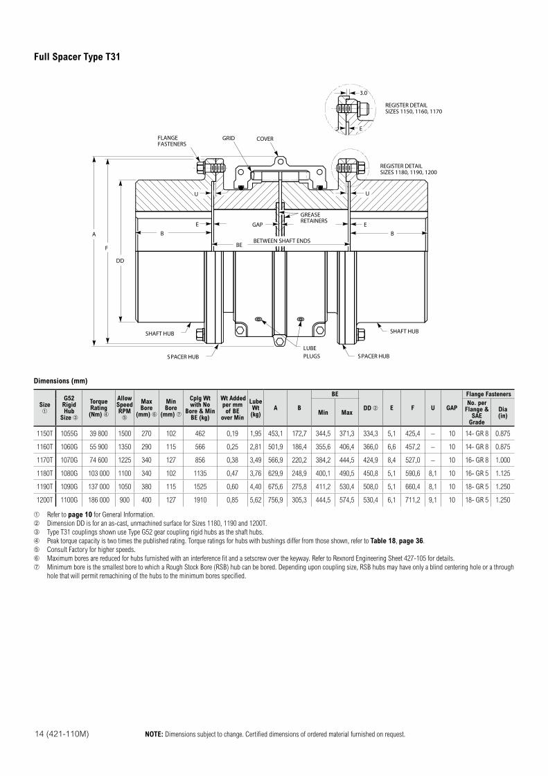
E
U
EB
GREASERETAINERSGAP
A
F
DD
BE
U
BEBETWEEN SHAFT ENDS
SHAFT HUB
SPACER HUBLUBEPLUGS SPACER HUB
SHAFT HUB
FLANGEFASTENERS
GRID COVER
REGISTER DETAILSIZES 1150, 1160, 1170
REGISTER DETAILSIZES 1180, 1190, 1200
3.0
Dimensions (mm)
Size G52
RigidHub
Size
TorqueRating(Nm)
AllowSpeedRPM
Max Bore
(mm)
MinBore
(mm)
Cplg Wtwith No
Bore & Min BE (kg)
Wt Addedper mmof BE
over Min
Lube Wt(kg)
A B
BE
DD E F U GAP
Flange Fasteners
Min Max
No. perFlange &
SAE Grade
Dia(in)
1150T 1055G 39 800 1500 270 102 462 0,19 1,95 453,1 172,7 344,5 371,3 334,3 5,1 425,4 – 10 14- GR 8 0.875
1160T 1060G 55 900 1350 290 115 566 0,25 2,81 501,9 186,4 355,6 406,4 366,0 6,6 457,2 – 10 14- GR 8 0.875
1170T 1070G 74 600 1225 340 127 856 0,38 3,49 566,9 220,2 384,2 444,5 424,9 8,4 527,0 – 10 16- GR 8 1.000
1180T 1080G 103 000 1100 340 102 1135 0,47 3,76 629,9 248,9 400,1 490,5 450,8 5,1 590,6 8,1 10 16- GR 5 1.125
1190T 1090G 137 000 1050 380 115 1525 0,60 4,40 675,6 275,8 411,2 530,4 508,0 5,1 660,4 8,1 10 18- GR 5 1.250
1200T 1100G 186 000 900 400 127 1910 0,85 5,62 756,9 305,3 444,5 574,5 530,4 6,1 711,2 9,1 10 18- GR 5 1.250
Refer to page 10 for General Information.
Dimension DD is for an as-cast, unmachined surface for Sizes 1180, 1190 and 1200T.
Type T31 couplings shown use Type G52 gear coupling rigid hubs as the shaft hubs.
Peak torque capacity is two times the published rating. Torque ratings for hubs with bushings differ from those shown, refer to Table 18, page 36.
Consult Factory for higher speeds.
Maximum bores are reduced for hubs furnished with an interference fit and a setscrew over the keyway. Refer to Rexnord Engineering Sheet 427-105 for details.
Minimum bore is the smallest bore to which a Rough Stock Bore (RSB) hub can be bored. Depending upon coupling size, RSB hubs may have only a blind centering hole or a through
hole that will permit remachining of the hubs to the minimum bores specified.
Full Spacer Type T31
NOTE: Dimensions subject to change. Certified dimensions of ordered material furnished on request. (421-110M) 15
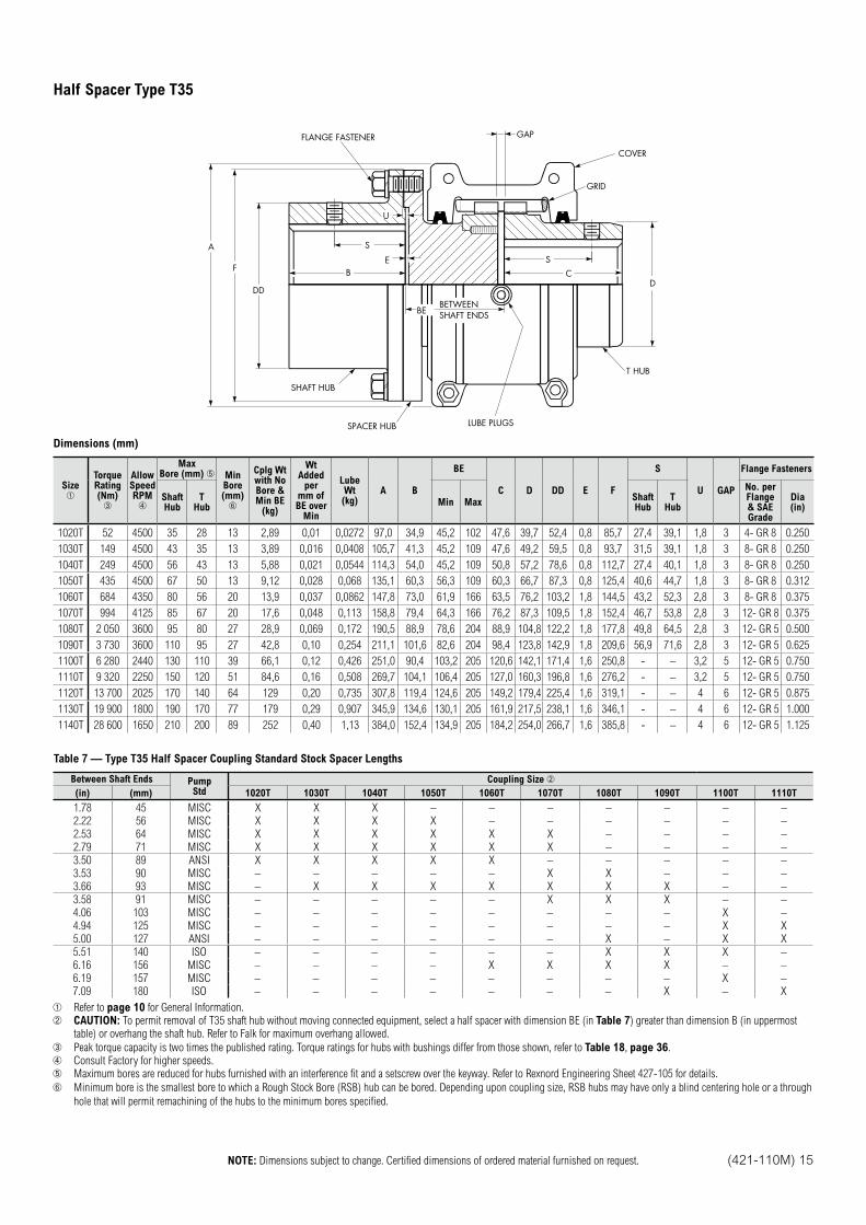
S
BE
U
S
CD
COVER
GRID
GAPFLANGE FASTENER
SHAFT HUB
A
F
DD
BEBETWEENSHAFT ENDS
SPACER HUB LUBE PLUGS
T HUB
Dimensions (mm)
SizeTorqueRating(Nm)
AllowSpeed RPM
MaxBore (mm) Min
Bore(mm)
Cplg Wtwith NoBore &Min BE
(kg)
WtAdded
permm ofBE over
Min
LubeWt(kg)
A B
BE
C D DD E F
S
U GAP
Flange Fasteners
ShaftHub
THub
Min MaxShaftHub
THub
No. per Flange & SAE Grade
Dia(in)
1020T 52 4500 35 28 13 2,89 0,01 0,0272 97,0 34,9 45,2 102 47,6 39,7 52,4 0,8 85,7 27,4 39,1 1,8 3 4- GR 8 0.250
1030T 149 4500 43 35 13 3,89 0,016 0,0408 105,7 41,3 45,2 109 47,6 49,2 59,5 0,8 93,7 31,5 39,1 1,8 3 8- GR 8 0.250
1040T 249 4500 56 43 13 5,88 0,021 0,0544 114,3 54,0 45,2 109 50,8 57,2 78,6 0,8 112,7 27,4 40,1 1,8 3 8- GR 8 0.250
1050T 435 4500 67 50 13 9,12 0,028 0,068 135,1 60,3 56,3 109 60,3 66,7 87,3 0,8 125,4 40,6 44,7 1,8 3 8- GR 8 0.312
1060T 684 4350 80 56 20 13,9 0,037 0,0862 147,8 73,0 61,9 166 63,5 76,2 103,2 1,8 144,5 43,2 52,3 2,8 3 8- GR 8 0.375
1070T 994 4125 85 67 20 17,6 0,048 0,113 158,8 79,4 64,3 166 76,2 87,3 109,5 1,8 152,4 46,7 53,8 2,8 3 12- GR 8 0.375
1080T 2 050 3600 95 80 27 28,9 0,069 0,172 190,5 88,9 78,6 204 88,9 104,8 122,2 1,8 177,8 49,8 64,5 2,8 3 12- GR 5 0.500
1090T 3 730 3600 110 95 27 42,8 0,10 0,254 211,1 101,6 82,6 204 98,4 123,8 142,9 1,8 209,6 56,9 71,6 2,8 3 12- GR 5 0.625
1100T 6 280 2440 130 110 39 66,1 0,12 0,426 251,0 90,4 103,2 205 120,6 142,1 171,4 1,6 250,8 - – 3,2 5 12- GR 5 0.750
1110T 9 320 2250 150 120 51 84,6 0,16 0,508 269,7 104,1 106,4 205 127,0 160,3 196,8 1,6 276,2 - – 3,2 5 12- GR 5 0.750
1120T 13 700 2025 170 140 64 129 0,20 0,735 307,8 119,4 124,6 205 149,2 179,4 225,4 1,6 319,1 - – 4 6 12- GR 5 0.875
1130T 19 900 1800 190 170 77 179 0,29 0,907 345,9 134,6 130,1 205 161,9 217,5 238,1 1,6 346,1 - – 4 6 12- GR 5 1.000
1140T 28 600 1650 210 200 89 252 0,40 1,13 384,0 152,4 134,9 205 184,2 254,0 266,7 1,6 385,8 - – 4 6 12- GR 5 1.125
Table 7 — Type T35 Half Spacer Coupling Standard Stock Spacer Lengths
Between Shaft Ends PumpStd
Coupling Size
(in) (mm) 1020T 1030T 1040T 1050T 1060T 1070T 1080T 1090T 1100T 1110T
1.78 45 MISC X X X – – – – – – –
2.22 56 MISC X X X X – – – – – –
2.53 64 MISC X X X X X X – – – –
2.79 71 MISC X X X X X X – – – –
3.50 89 ANSI X X X X X – – – – –
3.53 90 MISC – – – – – X X – – –
3.66 93 MISC – X X X X X X X – –
3.58 91 MISC – – – – – X X X – –
4.06 103 MISC – – – – – – – – X –
4.94 125 MISC – – – – – – – – X X
5.00 127 ANSI – – – – – – X – X X
5.51 140 ISO – – – – – – X X X –
6.16 156 MISC – – – – X X X X – –
6.19 157 MISC – – – – – – – – X –
7.09 180 ISO – – – – – – – X – X
Refer to page 10 for General Information.
CAUTION: To permit removal of T35 shaft hub without moving connected equipment, select a half spacer with dimension BE (in Table 7) greater than dimension B (in uppermost
table) or overhang the shaft hub. Refer to Falk for maximum overhang allowed.
Peak torque capacity is two times the published rating. Torque ratings for hubs with bushings differ from those shown, refer to Table 18, page 36.
Consult Factory for higher speeds.
Maximum bores are reduced for hubs furnished with an interference fit and a setscrew over the keyway. Refer to Rexnord Engineering Sheet 427-105 for details.
Minimum bore is the smallest bore to which a Rough Stock Bore (RSB) hub can be bored. Depending upon coupling size, RSB hubs may have only a blind centering hole or a through
hole that will permit remachining of the hubs to the minimum bores specified.
Half Spacer Type T35
16 (421-110M) NOTE: Dimensions subject to change. Certified dimensions of ordered material furnished on request.
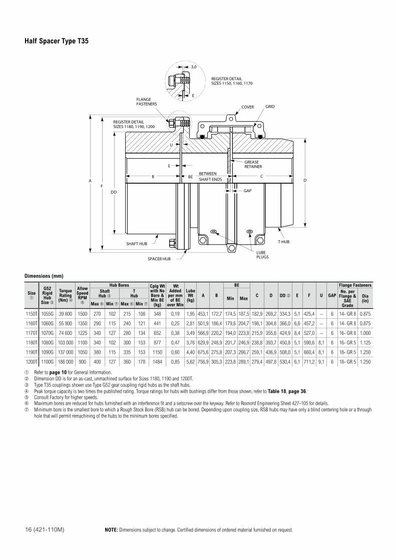
SHAFT HUB
SPACER HUBLUBEPLUGS
T-HUB
D
GAP
E
BEBETWEENSHAFT ENDS
GREASERETAINER
CBA
FDD
FLANGEFASTENERS
REGISTER DETAILSIZES 1180, 1190, 1200
U
COVER GRID
E
3,0
REGISTER DETAILSIZES 1150, 1160, 1170
Dimensions (mm)
SizeG52
RigidHub
Size
TorqueRating(Nm)
AllowSpeed RPM
Hub Bores Cplg Wtwith NoBore &Min BE
(kg)
Wt Added
per mmof BE
over Min
LubeWt(kg)
A B
BE
C D DD E F U GAP
Flange Fasteners
ShaftHub
THub
Min Max
No. perFlange &
SAE Grade
Dia(in)
Max Min Max Min
1150T 1055G 39 800 1500 270 102 215 108 348 0,19 1,95 453,1 172,7 174,5 187,5 182,9 269,2 334,3 5,1 425,4 – 6 14- GR 8 0.875
1160T 1060G 55 900 1350 290 115 240 121 441 0,25 2,81 501,9 186,4 179,6 204,7 198,1 304,8 366,0 6,6 457,2 – 6 14- GR 8 0.875
1170T 1070G 74 600 1225 340 127 280 134 652 0,38 3,49 566,9 220,2 194,0 223,8 215,9 355,6 424,9 8,4 527,0 – 6 16- GR 8 1.000
1180T 1080G 103 000 1100 340 102 300 153 877 0,47 3,76 629,9 248,9 201,7 246,9 238,8 393,7 450,8 5,1 590,6 8,1 6 16- GR 5 1.125
1190T 1090G 137 000 1050 380 115 335 153 1150 0,60 4,40 675,6 275,8 207,3 266,7 259,1 436,9 508,0 5,1 660,4 8,1 6 18- GR 5 1.250
1200T 1100G 186 000 900 400 127 360 178 1484 0,85 5,62 756,9 305,3 223,8 289,1 279,4 497,8 530,4 6,1 711,2 9,1 6 18- GR 5 1.250
Refer to page 10 for General Information.
Dimension DD is for an as-cast, unmachined surface for Sizes 1180, 1190 and 1200T.
Type T35 couplings shown use Type G52 gear coupling rigid hubs as the shaft hubs.
Peak torque capacity is two times the published rating. Torque ratings for hubs with bushings differ from those shown, refer to Table 18, page 36.
Consult Factory for higher speeds.
Maximum bores are reduced for hubs furnished with an interference fit and a setscrew over the keyway. Refer to Rexnord Engineering Sheet 427-105 for details.
Minimum bore is the smallest bore to which a Rough Stock Bore (RSB) hub can be bored. Depending upon coupling size, RSB hubs may have only a blind centering hole or a through
hole that will permit remachining of the hubs to the minimum bores specified.
Half Spacer Type T35
NOTE: Dimensions subject to change. Certified dimensions of ordered material furnished on request. (421-110M) 17
A
D
M
S
W
GAP
C
LUBRICATETHRU COVER
BY
N
E H
G
T41HUB
THUB
COVERCLEARANCE G
Type T41-2Type T41
DRIVINGEND
DRIVENEND
Dimensions (mm)
Size
Cplg Wtw/o Bore (kg) Lube
Wt(kg)
A B C D E G H M N S W Y GAP
T41 T41-2
1020T 6,17 – 0,0272 97,0 130,0 47,6 39,7 177,8 63,5 5,6 47,8 10,7 39,1 79,2 5,1 3
1030T 8,16 8,16 0,0408 105,7 130,0 47,6 49,2 201,7 69,6 5,6 50,8 10,7 39,1 79,2 5,1 3
1040T 11,5 11,3 0,0544 114,3 133,1 50,8 57,2 231,6 82,3 5,6 63,5 12,2 40,1 79,2 5,1 3
1050T 16,4 16,0 0,068 135,1 150,9 60,3 66,7 270,3 82,3 5,6 63,5 10,7 44,7 87,4 5,1 3
1060T 22,0 21,3 0,0862 147,8 163,1 63,5 76,2 301,2 88,9 8,1 76,2 15,2 52,3 96,5 5,1 3
1070T 28,2 27,3 0,113 158,8 182,9 76,2 87,3 323,6 101,6 8,1 82,8 14,7 53,8 103,6 5,1 3
1080T 41,0 40,3 0,172 190,5 206,2 88,9 104,8 361,7 101,6 8,1 91,9 14,7 64,5 114,3 5,1 3
1090T 62,6 60,3 0,254 211,1 230,1 98,4 123,8 413,5 127,0 8,1 109,2 16,3 71,6 128,5 5,1 3
1100T 101 91,6 0,426 251,0 269,2 120,6 142,1 491,2 139,7 – 147,3 20,8 – 143,8 5,3 5
1110T 128 121 0,508 269,7 288,3 127,0 160,3 543,1 152,4 – 152,4 21,8 – 156,5 9,1 5
1120T 183 174 0,735 307,8 341,1 149,2 179,4 590,3 177,8 – 177,8 26,9 – 185,4 9,1 6
1130T 260 249 0,907 345,9 360,9 161,9 217,5 683,8 190,5 – 185,4 26,9 – 192,5 9,1 6
1140T 376 360 1,13 384,0 389,1 184,2 254,0 766,6 203,2 – 213,4 27,2 – 198,6 8,9 6
1150T 502 – 1,95 453,1 434,6 182,9 269,2 863,6 215,9 – 254,0 31,8 – 245,4 9,1 6
1160T 652 – 2,81 501,9 454,9 198,1 304,8 988,6 215,9 – 254,0 32,3 – 250,4 9,1 6
1170T 869 – 3,49 566,9 490,0 215,9 355,6 1065,8 241,3 – 266,7 32,3 – 267,7 9,1 6
1180T 1161 – 3,76 629,9 536,7 238,8 393,7 1160,8 241,3 – 266,7 42,7 – 291,6 9,1 6
1190T 1426 – 4,4 675,6 562,6 259,1 436,9 1263,9 254,0 – 279,4 42,7 – 297,2 9,1 6
1200T 1805 – 5,62 756,9 601,2 279,4 497,8 1377,2 254,0 – 279,4 42,7 – 315,5 9,1 6
Refer to page 10 for General Information. Use a coupling guard that will permit air to circulate and cool the
coupling.
Weights are for couplings with Dimension C and W length hubs.
To remove cover without disturbing torque setting, allow M clearance.
With new friction segments.
Refer to Table 14 and Table 16 for maximum bores with square or rectangular keys.
Table 8 — T41 Slip Torques, Bores & Speeds
Slip Torque(Nm) Coupling
Size
Maximum Bore with
Recommended Keys (mm)
AllowSpeedRPM
Min MaxT41 Hub
T Hub
4.75 38 1020T41 24 28 3600
5.65 16 1030T41-232 35 3600
12.4 99 1030T41
6.78 26 1040T41-238 43 3600
20.9 167 1040T41
9.04 42 1050T41-245 50 3600
33.9 271 1050T41
11.3 73 1060T41-250 56 3600
58.8 470 1060T41
13.6 108 1070T41-260 67 3600
87.0 698 1070T41
44.1 192 1080T41-270 80 2800
153.0 1220 1080T41
74.6 316 1090T41-285 95 2500
254.0 2034 1090T41
136.0 576 1100T41-2100 110 2100
463.0 3706 1100T41
203 859 1110T41-2110 120 1850
689 5514 1110T41
294 1288 1120T41-2120 140 1750
1028 8225 1120T41
429 1830 1130T41-2145 170 1450
1469 11750 1130T41
610 2599 1140T41-2180 200 1300
2079 16631 1140T41
2938 23501 1150T41 190 215 1100
4067 32540 1160T41 225 240 950
5536 44290 1170T41 250 280 870
7570 60560 1180T41 290 300 760
10168 81349 1190T41 320 335 720
13558 108466 1200T41 340 360 670
Controlled Torque Types T41, T41-2
Controlled Torque Products
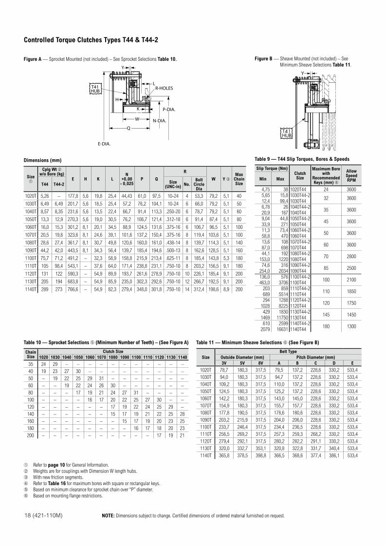
18 (421-110M) NOTE: Dimensions subject to change. Certified dimensions of ordered material furnished on request.
Figure A — Sprocket Mounted (not included) – See Sprocket Selections Table 10.
Y
L
K
H
P-DIA.
N-DIA.W
Q
R-HOLES
E-DIA.
T41HUB
Dimensions (mm)
Size
Cplg Wt w/o Bore (kg)
E H K LN
+0,00- 0,025
P Q
R
W Y Max
ChainSizeT44 T44-2
Size(UNC-in)
No.Bolt
CircleDia
1020T 5,26 – 177,8 5,6 19,8 25,4 44,43 61,0 97,5 10-24 4 53,3 79,2 5,1 40
1030T 6,49 6,49 201,7 5,6 18,5 25,4 57,2 76,2 104,1 10-24 6 66,0 79,2 5,1 50
1040T 8,57 8,35 231,6 5,6 13,5 22,4 66,7 91,4 113,3 .250-20 6 78,7 79,2 5,1 60
1050T 13,3 12,9 270,3 5,6 19,0 30,5 76,2 106,7 121,4 .312-18 6 91,4 87,4 5,1 80
1060T 16,0 15,3 301,2 8,1 20,1 34,5 88,9 124,5 131,6 .375-16 6 106,7 96,5 5,1 100
1070T 20,5 19,6 323,6 8,1 24,6 39,1 101,6 137,2 150,4 .375-16 8 119,4 103,6 5,1 100
1080T 28,6 27,4 361,7 8,1 30,7 49,8 120,6 160,0 161,0 .438-14 8 139,7 114,3 5,1 140
1090T 44,2 42,0 443,5 8,1 34,3 56,4 139,7 185,4 194,6 .500-13 8 162,6 128,5 5,1 160
1100T 75,7 71,2 491,2 – 32,3 58,9 158,8 215,9 213,4 .625-11 8 185,4 143,8 5,3 180
1110T 105 98,4 543,1 – 37,6 64,0 171,4 238,8 231,1 .750-10 8 203,2 156,5 9,1 180
1120T 131 122 590,3 – 54,9 89,9 193,7 261,6 278,9 .750-10 10 226,1 185,4 9,1 200
1130T 205 194 683,8 – 54,9 85,9 235,0 302,3 292,6 .750-10 12 266,7 192,5 9,1 200
1140T 289 273 766,6 – 54,9 82,3 279,4 348,0 301,8 .750-10 14 312,4 198,6 8,9 200
Figure B — Sheave Mounted (not included) – See
Minimum Sheave Selections Table 11.
T41HUB
Y
Table 9 — T44 Slip Torques, Bores & Speeds
Slip Torque (Nm)ClutchSize
Maximum Borewith
RecommendedKeys (mm)
AllowSpeedRPMMin Max
4,75 38 1020T44 24 3600
5,65 15,8 1030T44-232 3600
12,4 99,4 1030T44
6,78 26 1040T44-235 3600
20,9 167 1040T44
9,04 44,8 1050T44-245 3600
33,9 271 1050T44
11,3 73,4 1060T44-250 3600
58,8 470 1060T44
13,6 108 1070T44-260 3600
87,0 698 1070T44
44,1 192 1080T44-270 2800
153,0 1220 1080T44
74,6 316 1090T44-285 2500
254,0 2034 1090T44
136,0 576 1100T44-2100 2100
463,0 3706 1100T44
203 859 1110T44-2110 1850
689 5514 1110T44
294 1288 1120T44-2120 1750
1028 8225 1120T44
429 1830 1130T44-2145 1450
1469 11750 1130T44
610 2599 1140T44-2180 1300
2079 16631 1140T44
Table 10 — Sprocket Selections (Minimum Number of Teeth) – (See Figure A)
Chain Size
Clutch Size
1020 1030 1040 1050 1060 1070 1080 1090 1100 1110 1120 1130 1140
35 24 29 – – – – – – – – – – –
40 19 23 27 30 – – – – – – – – –
50 – 19 22 25 29 31 – – – – – – –
60 – – 19 22 24 26 30 – – – – – –
80 – – – 17 19 21 24 27 31 – – – –
100 – – – – 16 17 20 22 25 27 30 – –
120 – – – – – – 17 19 22 24 25 29 –
140 – – – – – – 15 17 19 21 22 25 28
160 – – – – – – – 15 17 19 20 23 25
180 – – – – – – – – 16 17 18 20 23
200 – – – – – – – – – – 17 19 21
Table 11 — Minimum Sheave Selections (See Figure B)
Size
Belt Type
Outside Diameter (mm) Pitch Diameter (mm)
3V 5V 8V A B C D E
1020T 78,7 180,3 317,5 79,5 137,2 228,6 330,2 533,4
1030T 94,0 180,3 317,5 94,7 137,2 228,6 330,2 533,4
1040T 109,2 180,3 317,5 110,0 137,2 228,6 330,2 533,4
1050T 124,5 180,3 317,5 125,2 137,2 228,6 330,2 533,4
1060T 142,2 180,3 317,5 143,0 145,0 228,6 330,2 533,4
1070T 154,9 180,3 317,5 155,7 157,7 228,6 330,2 533,4
1080T 177,8 190,5 317,5 178,6 180,6 228,6 330,2 533,4
1090T 203,2 215,9 317,5 204,0 206,0 228,6 330,2 533,4
1100T 233,7 246,4 317,5 234,4 236,5 228,6 330,2 533,4
1110T 256,5 269,2 317,5 257,3 259,3 268,2 330,2 533,4
1120T 279,4 292,1 317,5 280,2 282,2 291,1 330,2 533,4
1130T 320,0 332,7 353,1 320,8 322,8 331,7 340,4 533,4
1140T 365,8 378,5 398,8 366,5 368,6 377,4 386,1 533,4
Refer to page 10 for General Information.
Weights are for couplings with Dimension W length hubs.
With new friction segments.
Refer to Table 16 for maximum bores with square or rectangular keys.
Based on minimum clearance for sprocket chain over “P” diameter.
Based on mounting flange restrictions.
Controlled Torque Clutches Types T44 & T44-2
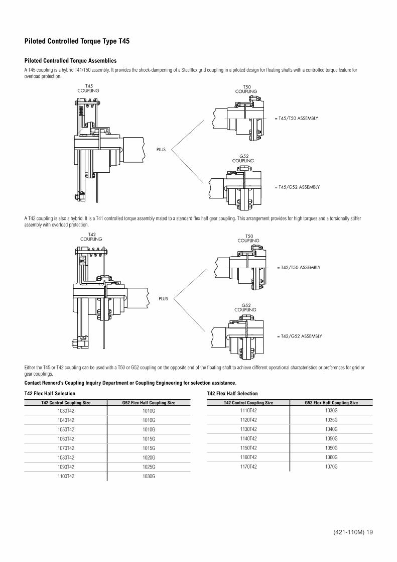
(421-110M) 19
Piloted Controlled Torque Assemblies
A T45 coupling is a hybrid T41/T50 assembly. It provides the shock-dampening of a Steelflex grid coupling in a piloted design for floating shafts with a controlled torque feature for
overload protection.
T45COUPLING
T50COUPLING
G52COUPLING
PLUS
= T45/T50 ASSEMBLY
= T45/G52 ASSEMBLY
A T42 coupling is also a hybrid. It is a T41 controlled torque assembly mated to a standard flex half gear coupling. This arrangement provides for high torques and a torsionally stiffer
assembly with overload protection.
T42COUPLING
T50COUPLING
G52COUPLING
PLUS
= T42/T50 ASSEMBLY
= T42/G52 ASSEMBLY
Either the T45 or T42 coupling can be used with a T50 or G52 coupling on the opposite end of the floating shaft to achieve different operational characteristics or preferences for grid or
gear couplings.
Contact Rexnord’s Coupling Inquiry Department or Coupling Engineering for selection assistance.
T42 Flex Half Selection
T42 Control Coupling Size G52 Flex Half Coupling Size
1030T42 1010G
1040T42 1010G
1050T42 1010G
1060T42 1015G
1070T42 1015G
1080T42 1020G
1090T42 1025G
1100T42 1030G
T42 Flex Half Selection
T42 Control Coupling Size G52 Flex Half Coupling Size
1110T42 1030G
1120T42 1035G
1130T42 1040G
1140T42 1050G
1150T42 1050G
1160T42 1060G
1170T42 1070G
Piloted Controlled Torque Type T45
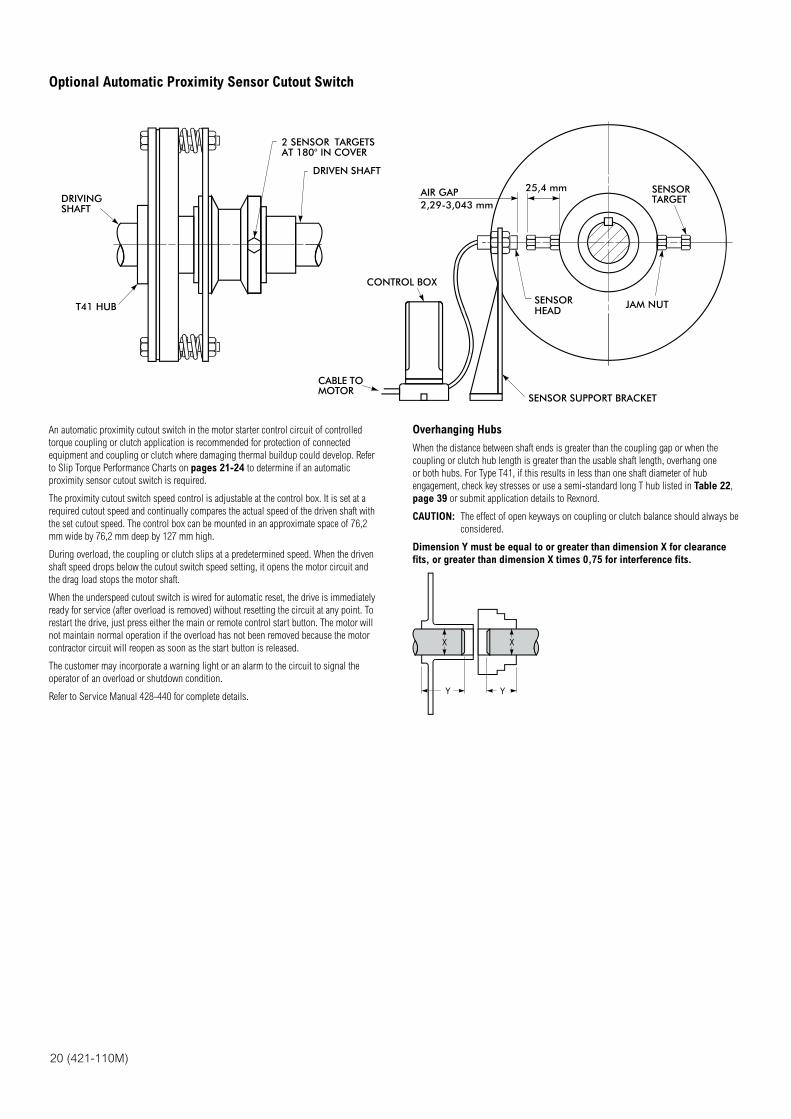
20 (421-110M)
DRIVINGSHAFT
T41 HUB
2 SENSOR TARGETSAT 180° IN COVER
DRIVEN SHAFT
CONTROL BOX
CABLE TO MOTOR
SENSOR SUPPORT BRACKET
SENSORHEAD
AIR GAP2,29-3,043 mm
25,4 mm
JAM NUT
SENSORTARGET
An automatic proximity cutout switch in the motor starter control circuit of controlled
torque coupling or clutch application is recommended for protection of connected
equipment and coupling or clutch where damaging thermal buildup could develop. Refer
to Slip Torque Performance Charts on pages 21-24 to determine if an automatic
proximity sensor cutout switch is required.
The proximity cutout switch speed control is adjustable at the control box. It is set at a
required cutout speed and continually compares the actual speed of the driven shaft with
the set cutout speed. The control box can be mounted in an approximate space of 76,2
mm wide by 76,2 mm deep by 127 mm high.
During overload, the coupling or clutch slips at a predetermined speed. When the driven
shaft speed drops below the cutout switch speed setting, it opens the motor circuit and
the drag load stops the motor shaft.
When the underspeed cutout switch is wired for automatic reset, the drive is immediately
ready for service (after overload is removed) without resetting the circuit at any point. To
restart the drive, just press either the main or remote control start button. The motor will
not maintain normal operation if the overload has not been removed because the motor
contractor circuit will reopen as soon as the start button is released.
The customer may incorporate a warning light or an alarm to the circuit to signal the
operator of an overload or shutdown condition.
Refer to Service Manual 428-440 for complete details.
Overhanging Hubs
When the distance between shaft ends is greater than the coupling gap or when the
coupling or clutch hub length is greater than the usable shaft length, overhang one
or both hubs. For Type T41, if this results in less than one shaft diameter of hub
engagement, check key stresses or use a semi-standard long T hub listed in Table 22,
page 39 or submit application details to Rexnord.
CAUTION: The effect of open keyways on coupling or clutch balance should always be
considered.
Dimension Y must be equal to or greater than dimension X for clearance
fits, or greater than dimension X times 0,75 for interference fits.
XX
Y Y
Optional Automatic Proximity Sensor Cutout Switch
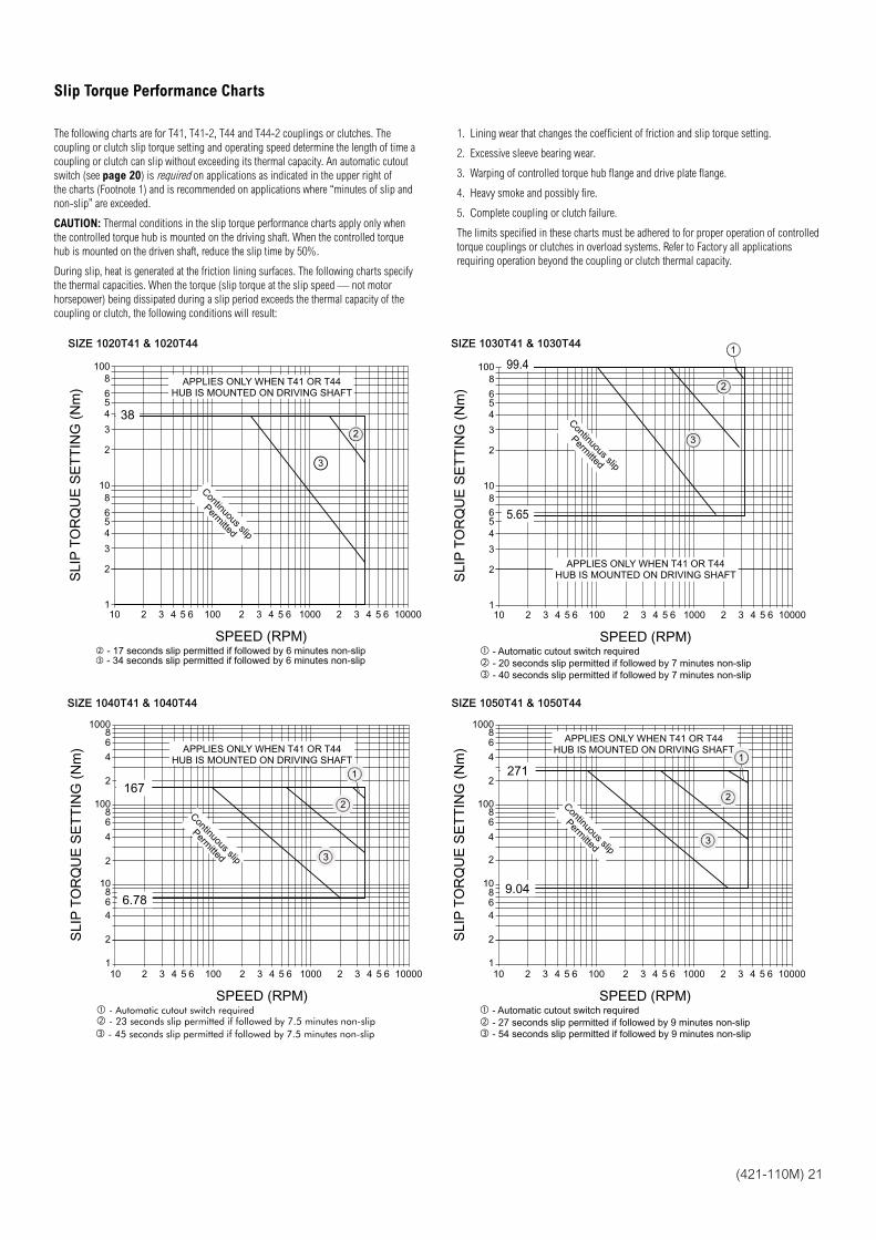
(421-110M) 21
The following charts are for T41, T41-2, T44 and T44-2 couplings or clutches. The
coupling or clutch slip torque setting and operating speed determine the length of time a
coupling or clutch can slip without exceeding its thermal capacity. An automatic cutout
switch (see page 20) is required on applications as indicated in the upper right of
the charts (Footnote 1) and is recommended on applications where “minutes of slip and
non-slip” are exceeded.
CAUTION: Thermal conditions in the slip torque performance charts apply only when
the controlled torque hub is mounted on the driving shaft. When the controlled torque
hub is mounted on the driven shaft, reduce the slip time by 50%.
During slip, heat is generated at the friction lining surfaces. The following charts specify
the thermal capacities. When the torque (slip torque at the slip speed — not motor
horsepower) being dissipated during a slip period exceeds the thermal capacity of the
coupling or clutch, the following conditions will result:
1. Lining wear that changes the coefficient of friction and slip torque setting.
2. Excessive sleeve bearing wear.
3. Warping of controlled torque hub flange and drive plate flange.
4. Heavy smoke and possibly fire.
5. Complete coupling or clutch failure.
The limits specified in these charts must be adhered to for proper operation of controlled
torque couplings or clutches in overload systems. Refer to Factory all applications
requiring operation beyond the coupling or clutch thermal capacity.
SIZE 1020T41 & 1020T44
SPEED (RPM)
SLI
P T
OR
QU
E S
ET
TIN
G (
Nm
)
100
10
110 65432 100 65432 1000 1000065432
2
3
4
4
56
8
2
3
56
8
3
- 17 seconds slip permitted if followed by 6 minutes non-slip - 34 seconds slip permitted if followed by 6 minutes non-slip
APPLIES ONLY WHEN T41 OR T44HUB IS MOUNTED ON DRIVING SHAFT
2
Continuous slip
Permitted
38
SIZE 1030T41 & 1030T44
SPEED (RPM)
SLI
P T
OR
QU
E S
ET
TIN
G (
Nm
)
100
10
110 65432 100 65432 1000 1000065432
2
3
4
8
2
3
54
6
56
8
- Automatic cutout switch required - 20 seconds slip permitted if followed by 7 minutes non-slip - 40 seconds slip permitted if followed by 7 minutes non-slip
Continuous slip
Permitted
APPLIES ONLY WHEN T41 OR T44HUB IS MOUNTED ON DRIVING SHAFT
3
2
1
99.4
5.65
SIZE 1040T41 & 1040T44
SPEED (RPM)
SLI
P T
OR
QU
E S
ET
TIN
G (
Nm
)
100
10
110 65432 100 65432 1000 1000065432
2
4
2
4
68
68
1000
4
68
- Automatic cutout switch required - 23 seconds slip permitted if followed by 7.5 minutes non-slip - 45 seconds slip permitted if followed by 7.5 minutes non-slip
2
6.78
167
Continuous slip
Permitted
APPLIES ONLY WHEN T41 OR T44HUB IS MOUNTED ON DRIVING SHAFT
3
1
2
SIZE 1050T41 & 1050T44
SPEED (RPM)
SLI
P T
OR
QU
E S
ET
TIN
G (
Nm
)
100
10
110 65432 100 65432 1000 1000065432
2
4
2
2
4
68
68
1000
4
68
- Automatic cutout switch required - 27 seconds slip permitted if followed by 9 minutes non-slip - 54 seconds slip permitted if followed by 9 minutes non-slip
9.04
271
Continuous slip
Permitted
APPLIES ONLY WHEN T41 OR T44HUB IS MOUNTED ON DRIVING SHAFT
3
1
2
Slip Torque Performance Charts
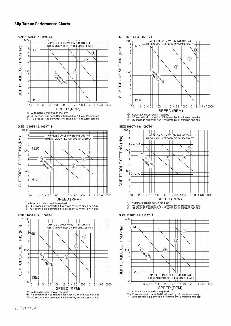
22 (421-110M)
SIZE 1060T41 & 1060T44
SPEED (RPM)
SLI
P T
OR
QU
E S
ET
TIN
G (
Nm
)
1000
100
1010 65432 100 65432 1000 1000065432
2
3
456
8
2
3
54
6
8
- Automatic cutout switch required - 30 seconds slip permitted if followed by 10 minutes non-slip - 60 seconds slip permitted if followed by 10 minutes non-slip
470
11.3
3
1
2
APPLIES ONLY WHEN T41 OR T44HUB IS MOUNTED ON DRIVING SHAFT
Continuous slip
Permitted
SIZE 1070T41 & 1070T44
SPEED (RPM)
SLI
P T
OR
QU
E S
ET
TIN
G (
Nm
)
1000
100
1010 65432 100 65432 1000 1000065432
2
3
456
8
2
3
54
6
8
- Automatic cutout switch required - 33 seconds slip permitted if followed by 11 minutes non-slip - 66 seconds slip permitted if followed by 11 minutes non-slip
696
13.6
Continuous slip
Permitted
APPLIES ONLY WHEN T41 OR T44HUB IS MOUNTED ON DRIVING SHAFT
3
1
2
SIZE 1080T41 & 1080T44
SPEED (RPM)
SLI
P T
OR
QU
E S
ET
TIN
G (
Nm
)
1000
100
1010 65432 100 65432 1000 1000065432
2
468
2
468
10000
2
468
- Automatic cutout switch required - 36 seconds slip permitted if followed by 12 minutes non-slip - 72 seconds slip permitted if followed by 12 minutes non-slip
1220
44.1
3
1
2
Continuous slip
Permitted
APPLIES ONLY WHEN T41 OR T44HUB IS MOUNTED ON DRIVING SHAFT
SIZE 1090T41 & 1090T44
SPEED (RPM)
SLI
P T
OR
QU
E S
ET
TIN
G (
Nm
)
1000
100
1010 65432 100 65432 1000 1000065432
2
468
2
468
10000
2
468
- Automatic cutout switch required - 40 seconds slip permitted if followed by 14 minutes non-slip - 80 seconds slip permitted if followed by 14 minutes non-slip
2034
74.6
Continuous slip
Permitted
APPLIES ONLY WHEN T41 OR T44HUB IS MOUNTED ON DRIVING SHAFT
3
1
2
SIZE 1100T41 & 1100T44
SPEED (RPM)
SLI
P T
OR
QU
E S
ET
TIN
G (
Nm
)
1000
10010 65432 100 65432 1000 1000065432
2
4
4
6
8
10000
2
6
8
- Automatic cutout switch required - 48 seconds slip permitted if followed by 16 minutes non-slip - 96 seconds slip permitted if followed by 16 minutes non-slip
3706
135.6
Continuous slip
Permitted
APPLIES ONLY WHEN T41 OR T44HUB IS MOUNTED ON DRIVING SHAFT
3
1
2
SIZE 1110T41 & 1110T44
SPEED (RPM)
SLI
P T
OR
QU
E S
ET
TIN
G (
Nm
)
1000
10010 65432 100 65432 1000 1000065432
2
4
6
8
10000
2
6
8
4
- Automatic cutout switch required - 55 seconds slip permitted if followed by 18 minutes non-slip - 110 seconds slip permitted if followed by 18 minutes non-slip
5514
203
Continuous slip
Permitted
APPLIES ONLY WHEN T41 OR T44HUB IS MOUNTED ON DRIVING SHAFT
3
1
2
Slip Torque Performance Charts
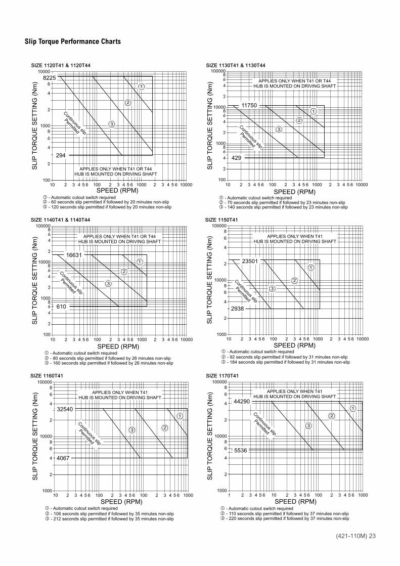
(421-110M) 23
SIZE 1120T41 & 1120T44
SPEED (RPM)
SLI
P T
OR
QU
E S
ET
TIN
G (
Nm
)
1000
10010 65432 100 65432 1000 1000065432
2
4
6
8
10000
2
6
8
4
Continuous slip
Permitted
APPLIES ONLY WHEN T41 OR T44HUB IS MOUNTED ON DRIVING SHAFT
3
1
2
- Automatic cutout switch required - 60 seconds slip permitted if followed by 20 minutes non-slip - 120 seconds slip permitted if followed by 20 minutes non-slip
8225
294
SIZE 1130T41 & 1130T44
SPEED (RPM)
SLI
P T
OR
QU
E S
ET
TIN
G (
Nm
)
10000
1000
100
2
468
2
468
100000
2
468
10 65432 100 65432 1000 1000065432
- Automatic cutout switch required - 70 seconds slip permitted if followed by 23 minutes non-slip - 140 seconds slip permitted if followed by 23 minutes non-slip
11750
429Continuous slip
Permitted
APPLIES ONLY WHEN T41 OR T44HUB IS MOUNTED ON DRIVING SHAFT
3
1
2
SIZE 1140T41 & 1140T44
SPEED (RPM)
SLI
P T
OR
QU
E S
ET
TIN
G (
Nm
)
10000
1000
100
2
468
2
468
100000
2
468
10 65432 100 65432 1000 1000065432
- Automatic cutout switch required - 80 seconds slip permitted if followed by 26 minutes non-slip - 160 seconds slip permitted if followed by 26 minutes non-slip
16631
610
Continuous slip
Permitted
APPLIES ONLY WHEN T41 OR T44HUB IS MOUNTED ON DRIVING SHAFT
3
1
2
SIZE 1150T41
SPEED (RPM)
SLI
P T
OR
QU
E S
ET
TIN
G (
Nm
)
100000
10000
1000
2
4
6
8
2
4
6
8
10 65432 100 65432 1000 1000065432
- Automatic cutout switch required - 92 seconds slip permitted if followed by 31 minutes non-slip - 184 seconds slip permitted if followed by 31 minutes non-slip
23501
2938
Continuous slip
Permitted
APPLIES ONLY WHEN T41HUB IS MOUNTED ON DRIVING SHAFT
3
1
2
SIZE 1160T41
SPEED (RPM)
SLI
P T
OR
QU
E S
ET
TIN
G (
Nm
)
100000
10000
1000
2
4
6
8
2
4
6
8
65432 100 65432 100 10006543210
- Automatic cutout switch required - 106 seconds slip permitted if followed by 35 minutes non-slip - 212 seconds slip permitted if followed by 35 minutes non-slip
32540
4067
Continuous slip
Permitted
APPLIES ONLY WHEN T41HUB IS MOUNTED ON DRIVING SHAFT
3
1
2
SIZE 1170T41
SPEED (RPM)
SLI
P T
OR
QU
E S
ET
TIN
G (
Nm
)
100000
10000
1000
2
4
6
8
2
4
6
8
1 65432 10 65432 100 100065432
- Automatic cutout switch required - 110 seconds slip permitted if followed by 37 minutes non-slip - 220 seconds slip permitted if followed by 37 minutes non-slip
44290
5536
Continuous slip
Permitted
APPLIES ONLY WHEN T41HUB IS MOUNTED ON DRIVING SHAFT
3
1
2
Slip Torque Performance Charts
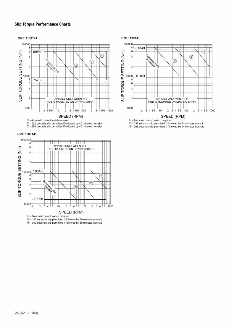
24 (421-110M)
SIZE 1180T41
SPEED (RPM)
SLI
P T
OR
QU
E S
ET
TIN
G (
Nm
)
100000
10000
1000
2
4
6
8
2
4
6
8
- Automatic cutout switch required - 122 seconds slip permitted if followed by 40 minutes non-slip - 224 seconds slip permitted if followed by 40 minutes non-slip
1 65432 10 65432 100 100065432
Continuous slip
Permitted
APPLIES ONLY WHEN T41HUB IS MOUNTED ON DRIVING SHAFT
3
1
2
60560
7570
SIZE 1190T41
SPEED (RPM)
SLI
P T
OR
QU
E S
ET
TIN
G (
Nm
)
100000
10000
1000
2
4
6
8
2
4
6
8
- Automatic cutout switch required - 133 seconds slip permitted if followed by 44 minutes non-slip - 266 seconds slip permitted if followed by 44 minutes non-slip
1 65432 10 65432 100 100065432
Continuous slip
Permitted
APPLIES ONLY WHEN T41HUB IS MOUNTED ON DRIVING SHAFT
3
1
2
81349
10169
SIZE 1200T41
SPEED (RPM)
SLI
P T
OR
QU
E S
ET
TIN
G (
Nm
)
1000000
100000
10000
2
4
6
8
2
4
6
8
- Automatic cutout switch required - 150 seconds slip permitted if followed by 50 minutes non-slip - 300 seconds slip permitted if followed by 50 minutes non-slip
1 65432 10 65432 100 100065432
108466
13558
Continuous slip
Permitted
APPLIES ONLY WHEN T41HUB IS MOUNTED ON DRIVING SHAFT
3
1
2
Slip Torque Performance Charts
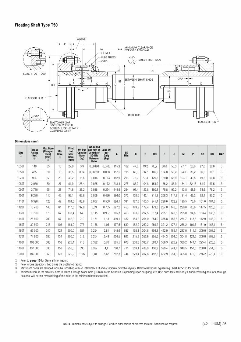
NOTE: Dimensions subject to change. Certified dimensions of ordered material furnished on request. (421-110M) 25
C C
GAP GAP
CD
FLANGED HUB
A
DD
P J
GASKET
MCOVER
LUBE PLUGSGRID
MINIMUM CLEARANCEFOR GRID REMOVAL
SIZES 1180 - 1200
SDF
BEBETWEEN SHAFT ENDS
PILOT HUB
SB
FLANGED HUB
GAP
ELASTOMER GAPDISC FOR VERTICALAPPLICATIONS - LOWERCOUPLING ONLY
SIZES 1120 - 1200
Dimensions (mm)
Size TorqueRating (Nm)
Max Bore (Flanged
Hub) (mm)
MinBore
PilotHubMax Bore (mm)
Wt PerCplg No
Bore (kg)
Wt Addedper mm ofLength of
SD DiaBetween
Hubs
Lube Wtper
Cplg (kg)
ABE Min
C D DD F J M P SB SD GAP
1030T 149 35 13 27,0 3,9 0,00498 0,0408 115,9 162 47,6 49,2 83,7 80,8 50,3 77,7 26,8 27,0 28,6 3
1050T 435 50 13 36,5 8,84 0,00893 0,068 157,5 195 60,3 66,7 105,2 104,8 59,2 94,0 36,2 36,5 38,1 3
1070T 994 67 20 49,2 15,6 0,016 0,113 182,9 213 76,2 87,3 126,5 129,0 65,9 103,1 49,8 49,2 50,8 3
1080T 2 050 80 27 61,9 26,4 0,025 0,172 218,4 275 88,9 104,8 154,9 156,2 85,9 134,1 52,13 61,9 63,5 3
1090T 3 730 95 27 74,6 37,2 0,036 0,254 244,9 294 98,4 123,8 180,3 175,8 92,2 143,8 58,5 74,6 76,2 3
1100T 6 280 110 42 92,1 62,8 0,056 0,426 286,0 372 120,6 142,1 211,3 208,3 117,3 181,4 69,3 92,1 95,2 5
1110T 9 320 120 42 101,6 83,6 0,067 0,508 324,1 391 127,0 160,3 245,4 228,6 122,2 190,5 73,9 101,6 104,8 5
1120T 13 700 140 61 117,5 97,9 0,09 0,735 327,2 453 149,2 179,4 179,3 257,0 146,3 220,0 83,6 117,5 120,6 6
1130T 19 900 170 67 133,4 140 0,115 0,907 365,3 463 161,9 217,5 217,4 295,1 149,5 225,0 94,8 133,4 136,5 6
1140T 28 600 200 67 142,9 210 0,131 1,13 419,1 482 184,2 254,0 254,0 335,8 155,8 234,7 113,8 142,9 146,0 6
1150T 39 800 215 108 161,9 277 0,168 1,95 477,5 549 182,9 269,2 269,2 391,2 177,4 268,2 101,7 161,9 165,1 6
1160T 55 900 240 121 200,0 381 0,254 2,81 548,6 587 198,1 304,8 304,8 442,0 189,4 287,0 111,9 200,0 203,2 6
1170T 74 600 280 134 200,0 519 0,254 3,49 604,5 622 215,9 355,6 355,6 494,3 201,0 304,8 124,6 200,0 203,2 6
1180T 103 000 300 153 225,4 718 0,322 3,76 665,5 673 238,8 393,7 393,7 556,3 226,9 330,2 141,4 225,4 228,6 6
1190T 137 000 335 153 250,8 898 0,397 4,4 708,7 711 259,1 436,9 436,9 599,4 241,7 349,5 157,6 250,8 254,0 6
1200T 186 000 360 178 276,2 1205 0,48 5,62 782,3 744 279,4 497,8 497,8 622,9 251,8 365,8 172,8 276,2 279,4 6
Refer to page 10 for General Information.
Peak torque capacity is two times the published rating.
Maximum bores are reduced for hubs furnished with an interference fit and a setscrew over the keyway. Refer to Rexnord Engineering Sheet 427-105 for details.
Minimum bore is the smallest bore to which a Rough Stock Bore (RSB) hub can be bored. Depending upon coupling size, RSB hubs may have only a blind centering hole or a through
hole that will permit remachining of the hubs to the minimum bores specified.
Floating Shaft Type T50
Specialty Couplings
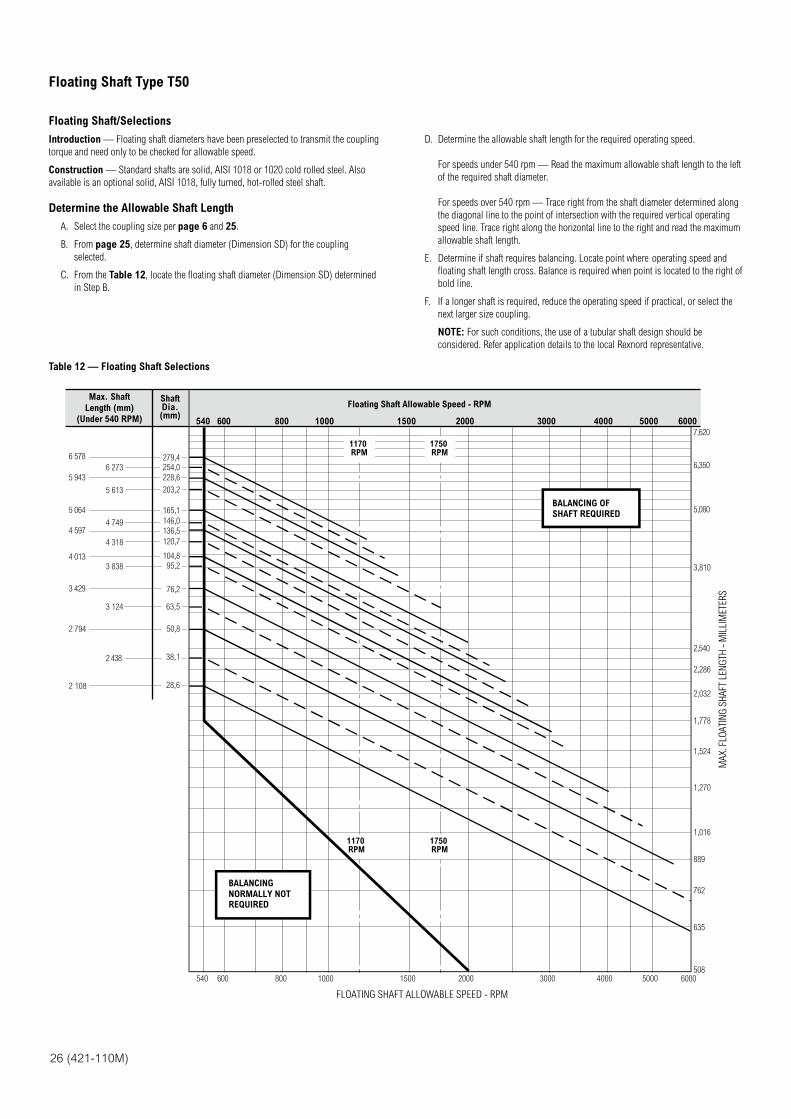
26 (421-110M)
Floating Shaft/Selections
Introduction — Floating shaft diameters have been preselected to transmit the coupling
torque and need only to be checked for allowable speed.
Construction — Standard shafts are solid, AISI 1018 or 1020 cold rolled steel. Also
available is an optional solid, AISI 1018, fully turned, hot-rolled steel shaft.
Determine the Allowable Shaft Length
A. Select the coupling size per page 6 and 25.
B. From page 25, determine shaft diameter (Dimension SD) for the coupling
selected.
C. From the Table 12, locate the floating shaft diameter (Dimension SD) determined
in Step B.
D. Determine the allowable shaft length for the required operating speed.
For speeds under 540 rpm — Read the maximum allowable shaft length to the left
of the required shaft diameter.
For speeds over 540 rpm — Trace right from the shaft diameter determined along
the diagonal line to the point of intersection with the required vertical operating
speed line. Trace right along the horizontal line to the right and read the maximum
allowable shaft length.
E. Determine if shaft requires balancing. Locate point where operating speed and
floating shaft length cross. Balance is required when point is located to the right of
bold line.
F. If a longer shaft is required, reduce the operating speed if practical, or select the
next larger size coupling.
NOTE: For such conditions, the use of a tubular shaft design should be
considered. Refer application details to the local Rexnord representative.
Table 12 — Floating Shaft Selections
6 578
5 943
5 064
4 597
4 013
3 429
2 794
2 108
6 273
5 613
4 749
4 318
3 838
3 124
2 438
279,4
254,0
228,6
203,2
165,1
76,2
50,8
540 600 800 1000 1500 2000 3000 4000 5000 6000
540 600 800 1000 1500 2000 3000 4000 5000 6000
1170RPM
1750RPM
1170RPM
1750RPM
7,620
6,350
5,080
3,810
2,540
MA
X. F
LOA
TIN
G S
HA
FT L
ENG
TH -
MIL
LIM
ETER
S
2,286
2,032
1,778
1,524
1,270
1,016
889
762
635
508
Max. Shaft
Length (mm)
(Under 540 RPM)
ShaftDia.(mm)
Floating Shaft Allowable Speed - RPM
FLOATING SHAFT ALLOWABLE SPEED - RPM
136,5
146,0
120,7
104,8
63,5
38,1
28,6
95,2
BALANCING OF
SHAFT REQUIRED
BALANCING
NORMALLY NOT
REQUIRED
Floating Shaft Type T50
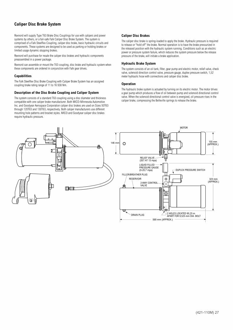
(421-110M) 27
Rexnord will supply Type T63 Brake Disc Couplings for use with calipers and power
systems by others, or a fail-safe Falk Caliper Disc Brake System. The system is
comprised of a Falk Steelflex Coupling, caliper disc brake, basic hydraulic circuits and
components. These systems are designed to be used as parking or holding brakes or
limited usage dynamic stopping brakes.
Rexnord will purchase for resale the caliper disc brakes and hydraulic components
preassembled in a power package.
Rexnord can assemble or mount the T63 coupling, disc brake and hydraulic system when
these components are ordered in conjunction with Falk gear drives.
Capabilities
The Falk Steelflex Disc Brake Coupling with Caliper Brake System has an assigned
coupling brake rating range of 11 to 16 938 Nm.
Description of the Disc Brake Coupling and Caliper System
The system consists of a standard T63 coupling using a disc diameter and thickness
compatible with one caliper brake manufacturer. Both MICO-Minnesota Automotive
Inc. and Goodyear Aerospace Corporation caliper disc brakes are used on Sizes 50T63
through 120T63 and 130T63, respectively. Both caliper manufacturers use different
mounting hole patterns and bracket styles. MICO and Goodyear caliper disc brakes
require hydraulic pressure.
Caliper Disc Brakes
The caliper disc brake is spring-loaded to apply the brake. Hydraulic pressure is required
to release or “hold off” the brake. Normal operation is to have the brake pressurized in
the released position with the hydraulic system running. Conditions such as an electric
power or pressure system failure, which reduces the system pressure below the release
pressure of the brake, will initiate a brake application.
Hydraulic Brake System
The system consists of an oil tank, filter, gear pump and electric motor, relief valve, check
valve, solenoid direction control valve, pressure gauge, duplex pressure switch, 1,52
meter hydraulic hose with connections and caliper disc brake.
Operation
The hydraulic brake system is actuated by turning on its electric motor. The motor drives
a gear pump which produces a flow of oil between pump and solenoid directional control
valve. When the solenoid directional control valve is energized, oil pressure rises in the
caliper brake, compressing the Belleville springs to release the brake.
RELIEF VALVE(SET AT 13 mpa)
LIQUID FILLEDPRESSURE GAUGE(0-20,7 mpa)
FILLER/BREATHER PLUG
RESERVOIR
2-WAY CONTROLVALVE
DRAIN PLUG2 HOLES LOCATED 95,25 mAPART FOR 9,525 mm DIA. BOLT
DUPLEX PRESSURE SWITCH
MOTOR
155 mm(APPROX.)
323 mm(APPROX.)
568 mm (APPROX.)
146 mm
Caliper Disc Brake System
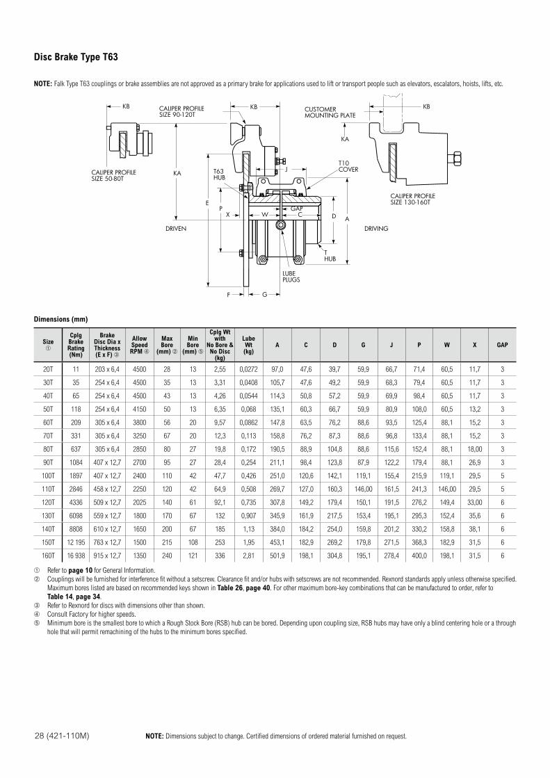
28 (421-110M) NOTE: Dimensions subject to change. Certified dimensions of ordered material furnished on request.
NOTE: Falk Type T63 couplings or brake assemblies are not approved as a primary brake for applications used to lift or transport people such as elevators, escalators, hoists, lifts, etc.
KB
KACALIPER PROFILESIZE 50-80T
T63HUB
CALIPER PROFILESIZE 90-120T
CUSTOMERMOUNTING PLATE
T10COVER
CALIPER PROFILESIZE 130-160T
THUB
GAP
LUBEPLUGS
EP
X W C D A
KB
KA
KB
J
GF
DRIVEN DRIVING
Dimensions (mm)
SizeCplgBrakeRating(Nm)
Brake Disc Dia x Thickness (E x F)
AllowSpeedRPM
MaxBore
(mm)
MinBore
(mm)
Cplg Wt with
No Bore & No Disc
(kg)
LubeWt(kg)
A C D G J P W X GAP
20T 11 203 x 6,4 4500 28 13 2,55 0,0272 97,0 47,6 39,7 59,9 66,7 71,4 60,5 11,7 3
30T 35 254 x 6,4 4500 35 13 3,31 0,0408 105,7 47,6 49,2 59,9 68,3 79,4 60,5 11,7 3
40T 65 254 x 6,4 4500 43 13 4,26 0,0544 114,3 50,8 57,2 59,9 69,9 98,4 60,5 11,7 3
50T 118 254 x 6,4 4150 50 13 6,35 0,068 135,1 60,3 66,7 59,9 80,9 108,0 60,5 13,2 3
60T 209 305 x 6,4 3800 56 20 9,57 0,0862 147,8 63,5 76,2 88,6 93,5 125,4 88,1 15,2 3
70T 331 305 x 6,4 3250 67 20 12,3 0,113 158,8 76,2 87,3 88,6 96,8 133,4 88,1 15,2 3
80T 637 305 x 6,4 2850 80 27 19,8 0,172 190,5 88,9 104,8 88,6 115,6 152,4 88,1 18,00 3
90T 1084 407 x 12,7 2700 95 27 28,4 0,254 211,1 98,4 123,8 87,9 122,2 179,4 88,1 26,9 3
100T 1897 407 x 12,7 2400 110 42 47,7 0,426 251,0 120,6 142,1 119,1 155,4 215,9 119,1 29,5 5
110T 2846 458 x 12,7 2250 120 42 64,9 0,508 269,7 127,0 160,3 146,00 161,5 241,3 146,00 29,5 5
120T 4336 509 x 12,7 2025 140 61 92,1 0,735 307,8 149,2 179,4 150,1 191,5 276,2 149,4 33,00 6
130T 6098 559 x 12,7 1800 170 67 132 0,907 345,9 161,9 217,5 153,4 195,1 295,3 152,4 35,6 6
140T 8808 610 x 12,7 1650 200 67 185 1,13 384,0 184,2 254,0 159,8 201,2 330,2 158,8 38,1 6
150T 12 195 763 x 12,7 1500 215 108 253 1,95 453,1 182,9 269,2 179,8 271,5 368,3 182,9 31,5 6
160T 16 938 915 x 12,7 1350 240 121 336 2,81 501,9 198,1 304,8 195,1 278,4 400,0 198,1 31,5 6
Refer to page 10 for General Information.
Couplings will be furnished for interference fit without a setscrew. Clearance fit and/or hubs with setscrews are not recommended. Rexnord standards apply unless otherwise specified.
Maximum bores listed are based on recommended keys shown in Table 26, page 40. For other maximum bore-key combinations that can be manufactured to order, refer to
Table 14, page 34.
Refer to Rexnord for discs with dimensions other than shown.
Consult Factory for higher speeds.
Minimum bore is the smallest bore to which a Rough Stock Bore (RSB) hub can be bored. Depending upon coupling size, RSB hubs may have only a blind centering hole or a through
hole that will permit remachining of the hubs to the minimum bores specified.
Disc Brake Type T63
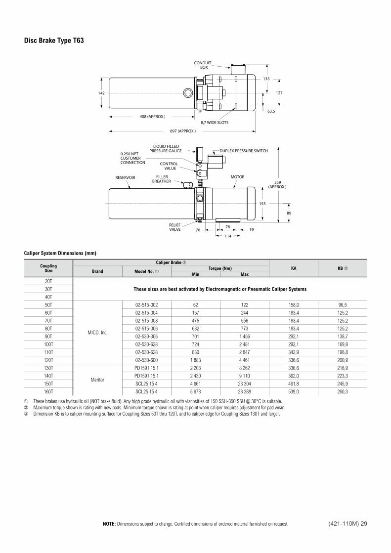
NOTE: Dimensions subject to change. Certified dimensions of ordered material furnished on request. (421-110M) 29
142
408 (APPROX.)
697 (APPROX.)
133
63,5
127
CONDUITBOX
359(APPROX.)
155
89
7619
11470
DUPLEX PRESSURE SWITCH
FILLERBREATHER
CONTROLVALUE
LIQUID FILLEDPRESSURE GAUGE
RELIEFVALVE
RESERVOIR MOTOR
8,7 WIDE SLOTS
0.250 NPTCUSTOMERCONNECTION
Caliper System Dimensions (mm)
CouplingSize
Caliper Brake
KA KB Brand Model No.
Torque (Nm)
Min Max
20T
These sizes are best activated by Electromagnetic or Pneumatic Caliper Systems30T
40T
50T
MICO, Inc.
02-515-002 62 122 158,0 96,5
60T 02-515-004 157 244 183,4 125,2
70T 02-515-008 475 556 183,4 125,2
80T 02-515-006 632 773 183,4 125,2
90T 02-530-306 701 1 456 292,1 138,7
100T 02-530-628 724 2 481 292,1 169,9
110T 02-530-628 830 2 847 342,9 196,8
120T 02-530-600 1 883 4 461 336,6 200,9
130T
Meritor
PD1591 15 1 2 203 8 262 336,6 216,9
140T PD1591 15 1 2 430 9 110 362,0 223,3
150T SCL25 15 4 4 661 23 304 461,8 245,9
160T SCL25 15 4 5 678 28 388 539,0 260,3
These brakes use hydraulic oil (NOT brake fluid). Any high grade hydraulic oil with viscosities of 150 SSU-350 SSU @ 38°C is suitable.
Maximum torque shown is rating with new pads. Minimum torque shown is rating at point when caliper requires adjustment for pad wear.
Dimension KB is to caliper mounting surface for Coupling Sizes 50T thru 120T, and to caliper edge for Coupling Sizes 130T and larger.
Disc Brake Type T63
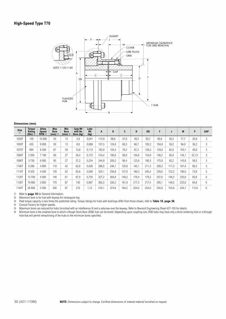
30 (421-110M) NOTE: Dimensions subject to change. Certified dimensions of ordered material furnished on request.
COVER
LUBE PLUGSGRID
GAP
MINIMUM CLEARANCEFOR GRID REMOVAL
T HUB
GASKET
FLANGEDHUB
SIZES 1120-1140
A
J
M
C CD F
DD
P
B
Dimensions (mm)
Size TorqueRating(Nm)
AllowSpeedRPM
Max Bore
(mm)
MinBore
(mm)
Cplg Wtwith No
Bore (kg)
Lube Wt(kg)
A B C D DD F J M P GAP
1030T 149 10 000 35 13 3,9 0,041 115,9 98,6 47,6 49,2 83,7 80,8 50,3 77,7 26,8 3
1050T 435 9 000 50 13 8,8 0,068 157,5 124,0 60,3 66,7 105,2 104,8 59,2 94,0 36,2 3
1070T 994 8 200 67 20 15,6 0,113 182,9 155,4 76,2 87,3 126,5 129,0 65,9 103,1 49,8 3
1080T 2 050 7 100 80 27 26,4 0,172 218,4 180,8 88,9 104,8 154,9 156,2 85,9 134,1 52,13 3
1090T 3 730 6 000 95 27 37,2 0,254 244,9 200,2 98,4 123,8 180,3 175,8 92,2 143,8 58,5 3
1100T 6 280 4 900 110 42 62,8 0,426 286,0 246,1 120,6 142,1 211,3 208,3 117,3 181,4 69,3 5
1110T 9 320 4 500 120 42 83,6 0,508 324,1 258,8 127,0 160,3 245,4 228,6 122,2 190,5 73,9 5
1120T 13 700 4 000 140 61 97,9 0,735 327,2 304,8 149,2 179,4 179,3 257,0 146,3 220,0 83,6 6
1130T 19 900 3 600 170 67 140 0,907 365,3 330,2 161,9 217,5 217,4 295,1 149,5 225,0 94,8 6
1140T 28 600 3 300 200 67 210 1,13 419,1 374,6 184,2 254,0 254,0 335,8 155,8 234,7 113,8 6
Refer to page 10 for General Information.
Maximum bore is for hub with keyway for rectangular key.
Peak torque capacity is two times the published rating. Torque ratings for hubs with bushings differ from those shown, refer to Table 18, page 36.
Consult Factory for higher speeds.
Maximum bores are reduced for hubs furnished with an interference fit and a setscrew over the keyway. Refer to Rexnord Engineering Sheet 427-105 for details.
Minimum bore is the smallest bore to which a Rough Stock Bore (RSB) hub can be bored. Depending upon coupling size, RSB hubs may have only a blind centering hole or a through
hole that will permit remachining of the hubs to the minimum bores specified.
High-Speed Type T70
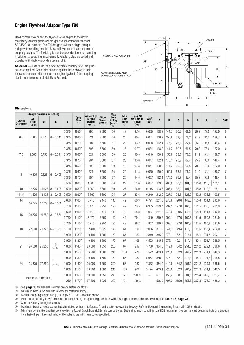
NOTE: Dimensions subject to change. Certified dimensions of ordered material furnished on request. (421-110M) 31
Used primarily to connect the flywheel of an engine to the driven
machinery. Adapter plates are designed to accommodate standard
SAE J620 bolt patterns. The T90 design provides for higher torque
ratings with resulting smaller sizes and lower costs than elastomeric
coupling designs. The flexible gridmember provides torsional damping
in addition to accepting misalignment. Adapter plates are bolted and
doweled to the hub to provide a secure joint.
Selection — Determine the proper Steelflex coupling size using the
selection method. Check size selected against those shown in table
below for the clutch size used on the engine flywheel. If the coupling
size is not shown, refer all details to Rexnord.
Dimensions
Adapter (values in inches)
CplgSize
AssemblyTorqueRating(Nm)
AllowSpeedRPM
MaxBore
Sq Key (mm)
MinBore (mm)
Cplg WtNo Bore In
T-Hub(kg)
WR2
(kg2)A B C D J L U GAPClutch
Diameter
AF+.000- .005
BC G T
6.5 8.500 7.875 6 – 0.344
0.375 1050T 395 3 600 50 13 8,16 0,025 138,2 141,7 60,5 66,5 79,2 78,0 127,0 3
0.375 1060T 621 3 600 56 20 10,4 0,031 150,9 150,9 63,5 76,2 91,9 84,1 139,7 3
0.375 1070T 904 3 600 67 20 13,2 0,038 162,1 176,3 76,2 87,4 95,2 96,8 149,4 3
7.5 9.500 8.750 8 – 0.344
0.375 1050T 395 3 600 50 13 9,07 0,034 138,2 141,7 60,5 66,5 79,2 78,0 127,0 3
0.375 1060T 621 3 600 56 20 10,9 0,040 150,9 150,9 63,5 76,2 91,9 84,1 139,7 3
0.375 1070T 904 3 600 67 20 13,6 0,047 162,1 176,3 76,2 87,4 95,2 96,8 149,4 3
8 10.375 9.625 6 – 0.406
0.375 1050T 395 3 600 50 13 9,53 0,044 138,2 141,7 60,5 66,5 79,2 78,0 127,0 3
0.375 1060T 621 3 600 56 20 11,8 0,050 150,9 150,9 63,5 76,2 91,9 84,1 139,7 3
0.375 1070T 904 3 600 67 20 14,5 0,057 162,1 176,3 76,2 87,4 95,2 96,8 149,4 3
0.500 1080T 1 860 3 600 80 27 21,8 0,097 193,5 205,0 88,9 104,6 115,8 112,8 165,1 3
10 12.375 11.625 8 – 0.406 0.500 1080T 1 860 3 600 80 27 24,0 0,145 193,5 205,0 88,9 104,6 115,8 112,8 165,1 3
11.5 13.875 13.125 8 – 0.406 0.500 1090T 3 390 3 600 95 27 33,6 0,240 212,9 227,3 98,6 124,0 122,2 125,5 190,5 3
1418.375 17.250 8 – 0.531
0.650 1100T 5 710 2 440 110 42 60,3 0,791 251,0 276,9 120,6 142,0 155,4 151,4 212,9 5
0.750 1110T 8 470 2 250 120 42 73,5 0,965 269,7 292,1 127,0 160,3 161,5 160,3 231,9 5
16 20.375 19.250 8 – 0.5310.650 1100T 5 710 2 440 110 42 65,8 1,097 251,0 276,9 120,6 142,0 155,4 151,4 212,9 5
0.750 1110T 8 470 2 250 120 42 79,4 1,319 269,7 292,1 127,0 160,3 161,5 160,3 231,9 5
18 22.500 21.375 6 – 0.656
0.750 1110T 5 710 2 250 120 42 86,2 1,827 269,7 292,1 127,0 160,3 161,5 160,3 231,9 5
0.750 1120T 12 400 2 025 140 61 110 2,096 307,8 341,1 149,4 179,3 191,5 185,4 254,0 6
0.900 1130T 10 100 1 800 170 67 150 2,849 345,9 373,1 162,1 217,4 195,1 204,7 292,1 6
21 26.500 25.25012 – 0.656
0.900 1130T 10 100 1 800 170 67 168 4,553 345,9 373,1 162,1 217,4 195,1 204,7 298,5 6
1.000 1140T 26 000 1 650 200 67 217 5,768 384,0 419,9 184,2 254,0 201,2 229,4 336,6 6
1.000 1150T 36 200 1 500 215 108 276 7,572 453,1 420,6 182,9 269,2 271,3 231,4 349,3 6
24 28.875 27.25012 – 0.812
0.900 1130T 10 100 1 800 170 67 180 5,987 345,9 373,1 162,1 217,4 195,1 204,7 298,5 6
1.000 1140T 26 000 1 650 200 67 230 7,332 384,0 419,9 184,2 254,0 201,2 229,4 336,6 6
1.000 1150T 36 200 1 500 215 108 289 9,174 453,1 420,6 182,9 269,2 271,3 231,4 349,3 6
Machined as Required1.000 1160T 50 800 1 350 240 121 298 – 501,9 453,4 198,1 304,8 278,4 248,9 393,7 6
1.250 1170T 67 800 1 225 280 134 409 – 566,9 495,3 215,9 355,6 307,3 273,0 438,2 6
See page 10 for General Information and Reference Notes.
Maximum bore is for hub with keyway for rectangular key.
For total coupling weight add [0,101 x (AF2 - U2) x T] to value shown.
Peak torque capacity is two times the published rating. Torque ratings for hubs with bushings differ from those shown, refer to Table 18, page 36.
Consult Factory for higher speeds.
Maximum bores are reduced for hubs furnished with an interference fit and a setscrew over the keyway. Refer to Rexnord Engineering Sheet 427-105 for details.
Minimum bore is the smallest bore to which a Rough Stock Bore (RSB) hub can be bored. Depending upon coupling size, RSB hubs may have only a blind centering hole or a through
hole that will permit remachining of the hubs to the minimum bores specified.
G - (NO. – DIA. OF HOLES)
ADAPTER BOLTED ANDDOWELED TO HUB BY FALK
ADAPTER
LUBEPLUGS
COVER
GRID
T-HUB
GAP
J
DA
C
B
L
BC
AF
T
U
Engine Flywheel Adapter Type T90
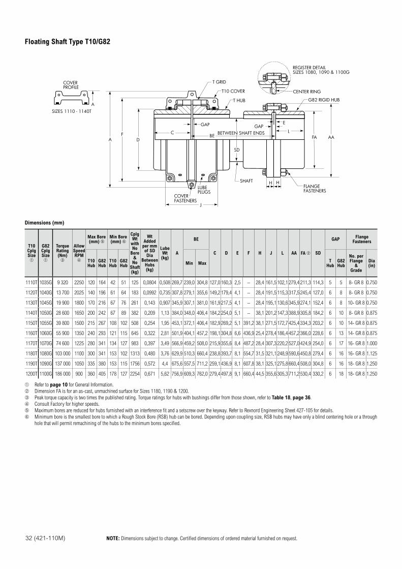
32 (421-110M) NOTE: Dimensions subject to change. Certified dimensions of ordered material furnished on request.
SD
GAPGAP
BEL
E
C
D
FLANGEFASTENERS
SHAFTLUBEPLUGS
COVERFASTENERS
H H
F
G82 RIGID HUB
CENTER RING
T HUB
T10 COVER
REGISTER DETAILSIZES 1080, 1090 & 1100G
J
AAFABETWEEN SHAFT ENDS
COVERPROFILE
SIZES 1110 - 1140TA
T GRID
A
Dimensions (mm)
T10CplgSize
G82CplgSize
TorqueRating(Nm)
AllowSpeed RPM
Max Bore (mm)
Min Bore (mm)
Cplg Wt
with No
Bore &No
Shaft(kg)
WtAdded
per mmof SDDia
BetweenHubs(kg)
LubeWt(kg)
A
BE
C D E F H J L AA FA SD
GAPFlange
Fasteners
T10Hub
G82Hub
T10Hub
G82Hub
Min MaxT
HubG82Hub
No. perFlange
&Grade
Dia(in)
1110T 1035G 9 320 2250 120 164 42 51 125 0,0804 0,508 269,7 239,0 304,8 127,0 160,3 2,5 – 28,4 161,5 102,1 279,4 211,3 114,3 5 5 8- GR 8 0.750
1120T 1040G 13 700 2025 140 196 61 64 183 0,0992 0,735 307,8 279,1 355,6 149,2 179,4 4,1 – 28,4 191,5 115,3 317,5 245,4 127,0 6 8 8- GR 8 0.750
1130T 1045G 19 900 1800 170 216 67 76 261 0,143 0,907 345,9 307,1 381,0 161,9 217,5 4,1 – 28,4 195,1 130,6 345,9 274,1 152,4 6 8 10- GR 8 0.750
1140T 1050G 28 600 1650 200 242 67 89 382 0,209 1,13 384,0 348,0 406,4 184,2 254,0 5,1 – 38,1 201,2 147,3 388,9 305,8 184,2 6 10 8- GR 8 0.875
1150T 1055G 39 800 1500 215 267 108 102 508 0,254 1,95 453,1 372,1 406,4 182,9 269,2 5,1 391,2 38,1 271,5 172,7 425,4 334,3 203,2 6 10 14- GR 8 0.875
1160T 1060G 55 900 1350 240 293 121 115 645 0,322 2,81 501,9 404,1 457,2 198,1 304,8 6,6 436,9 25,4 278,4 186,4 457,2 366,0 228,6 6 13 14- GR 8 0.875
1170T 1070G 74 600 1225 280 341 134 127 983 0,397 3,49 566,9 459,2 508,0 215,9 355,6 8,4 487,2 28,4 307,3 220,2 527,0 424,9 254,0 6 17 16- GR 8 1.000
1180T 1080G 103 000 1100 300 341 153 102 1313 0,480 3,76 629,9 510,3 660,4 238,8 393,7 8,1 554,7 31,5 321,1 248,9 590,6 450,8 279,4 6 16 16- GR 8 1.125
1190T 1090G 137 000 1050 335 380 153 115 1756 0,572 4,4 675,6 557,5 711,2 259,1 436,9 8,1 607,8 38,1 325,1 275,8 660,4 508,0 304,8 6 16 18- GR 8 1.250
1200T 1100G 186 000 900 360 405 178 127 2254 0,671 5,62 756,9 609,3 762,0 279,4 497,8 9,1 660,4 44,5 355,6 305,3 711,2 530,4 330,2 6 18 18- GR 8 1.250
Refer to page 10 for General Information.
Dimension FA is for an as-cast, unmachined surface for Sizes 1180, 1190 & 1200.
Peak torque capacity is two times the published rating. Torque ratings for hubs with bushings differ from those shown, refer to Table 18, page 36.
Consult Factory for higher speeds.
Maximum bores are reduced for hubs furnished with an interference fit and a setscrew over the keyway. Refer to Rexnord Engineering Sheet 427-105 for details.
Minimum bore is the smallest bore to which a Rough Stock Bore (RSB) hub can be bored. Depending upon coupling size, RSB hubs may have only a blind centering hole or a through
hole that will permit remachining of the hubs to the minimum bores specified.
Floating Shaft Type T10/G82
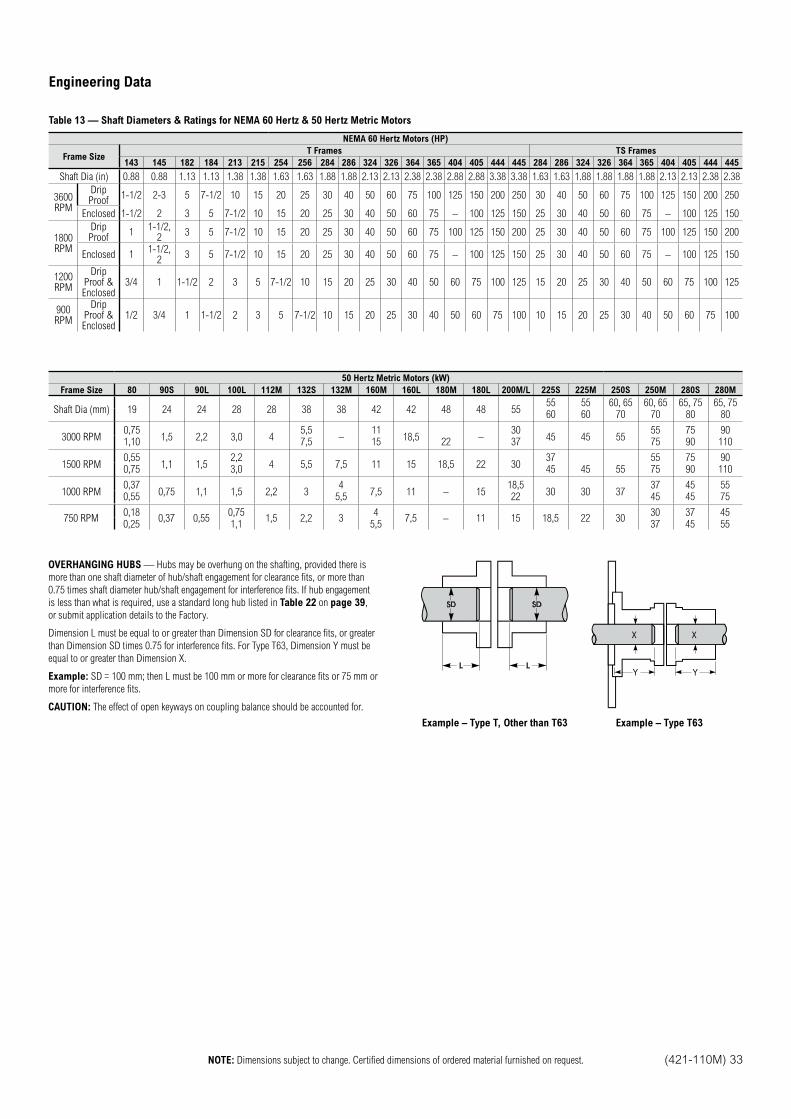
NOTE: Dimensions subject to change. Certified dimensions of ordered material furnished on request. (421-110M) 33
Engineering Data
Table 13 — Shaft Diameters & Ratings for NEMA 60 Hertz & 50 Hertz Metric Motors
NEMA 60 Hertz Motors (HP)
Frame SizeT Frames TS Frames
143 145 182 184 213 215 254 256 284 286 324 326 364 365 404 405 444 445 284 286 324 326 364 365 404 405 444 445
Shaft Dia (in) 0.88 0.88 1.13 1.13 1.38 1.38 1.63 1.63 1.88 1.88 2.13 2.13 2.38 2.38 2.88 2.88 3.38 3.38 1.63 1.63 1.88 1.88 1.88 1.88 2.13 2.13 2.38 2.38
3600 RPM
Drip Proof
1-1/2 2-3 5 7-1/2 10 15 20 25 30 40 50 60 75 100 125 150 200 250 30 40 50 60 75 100 125 150 200 250
Enclosed 1-1/2 2 3 5 7-1/2 10 15 20 25 30 40 50 60 75 – 100 125 150 25 30 40 50 60 75 – 100 125 150
1800 RPM
Drip Proof
11-1/2,
23 5 7-1/2 10 15 20 25 30 40 50 60 75 100 125 150 200 25 30 40 50 60 75 100 125 150 200
Enclosed 11-1/2,
23 5 7-1/2 10 15 20 25 30 40 50 60 75 – 100 125 150 25 30 40 50 60 75 – 100 125 150
1200 RPM
Drip Proof & Enclosed
3/4 1 1-1/2 2 3 5 7-1/2 10 15 20 25 30 40 50 60 75 100 125 15 20 25 30 40 50 60 75 100 125
900 RPM
Drip Proof & Enclosed
1/2 3/4 1 1-1/2 2 3 5 7-1/2 10 15 20 25 30 40 50 60 75 100 10 15 20 25 30 40 50 60 75 100
50 Hertz Metric Motors (kW)
Frame Size 80 90S 90L 100L 112M 132S 132M 160M 160L 180M 180L 200M/L 225S 225M 250S 250M 280S 280M
Shaft Dia (mm) 19 24 24 28 28 38 38 42 42 48 48 5555 55 60, 65 60, 65 65, 75 65, 7560 60 70 70 80 80
3000 RPM0,75
1,5 2,2 3,0 45,5
–11
18,5 –30
45 45 5555 75 90
1,10 7,5 15 22 37 75 90 110
1500 RPM0,55
1,1 1,52,2
4 5,5 7,5 11 15 18,5 22 3037 55 75 90
0,75 3,0 45 45 55 75 90 110
1000 RPM0,37
0,75 1,1 1,5 2,2 34
7,5 11 – 1518,5
30 30 3737 45 55
0,55 5,5 22 45 45 75
750 RPM0,18
0,37 0,550,75
1,5 2,2 34
7,5 – 11 15 18,5 22 3030 37 45
0,25 1,1 5,5 37 45 55
OVERHANGING HUBS — Hubs may be overhung on the shafting, provided there is
more than one shaft diameter of hub/shaft engagement for clearance fits, or more than
0.75 times shaft diameter hub/shaft engagement for interference fits. If hub engagement
is less than what is required, use a standard long hub listed in Table 22 on page 39,
or submit application details to the Factory.
Dimension L must be equal to or greater than Dimension SD for clearance fits, or greater
than Dimension SD times 0.75 for interference fits. For Type T63, Dimension Y must be
equal to or greater than Dimension X.
Example: SD = 100 mm; then L must be 100 mm or more for clearance fits or 75 mm or
more for interference fits.
CAUTION: The effect of open keyways on coupling balance should be accounted for.
XX
Y Y
Example – Type T, Other than T63 Example – Type T63
Technical Data
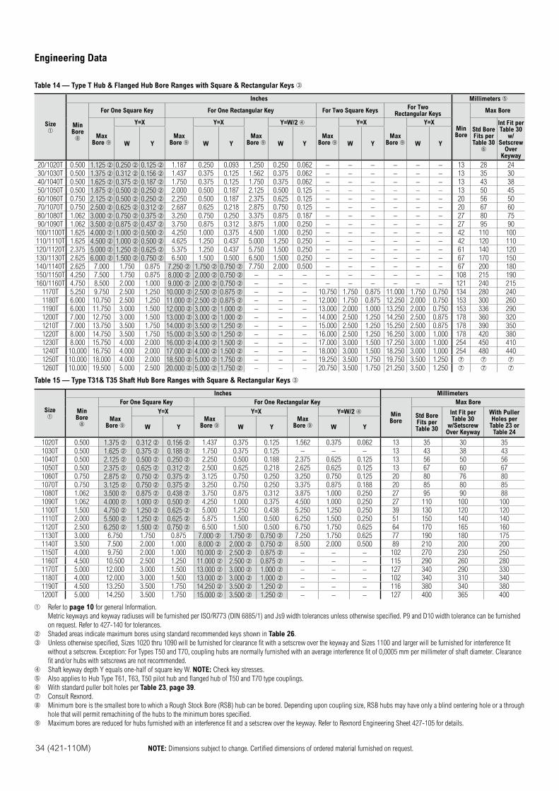
34 (421-110M) NOTE: Dimensions subject to change. Certified dimensions of ordered material furnished on request.
Engineering Data
Table 14 — Type T Hub & Flanged Hub Bore Ranges with Square & Rectangular Keys
Size
Inches Millimeters
MinBore
For One Square Key For One Rectangular Key For Two Square KeysFor Two
Rectangular Keys
MinBore
Max Bore
MaxBore
Y=X
MaxBore
Y=X
MaxBore
Y=W/2
MaxBore
Y=X
MaxBore
Y=XStd Bore Fits per Table 30
Int Fit per Table 30
w/Setscrew
Over Keyway
W Y W Y W Y W Y W Y
20/1020T 0.500 1.125 0.250 0.125 1.187 0.250 0.093 1.250 0.250 0.062 – – – – – – 13 28 24
30/1030T 0.500 1.375 0.312 0.156 1.437 0.375 0.125 1.562 0.375 0.062 – – – – – – 13 35 30
40/1040T 0.500 1.625 0.375 0.187 1.750 0.375 0.125 1.750 0.375 0.062 – – – – – – 13 43 38
50/1050T 0.500 1.875 0.500 0.250 2.000 0.500 0.187 2.125 0.500 0.125 – – – – – – 13 50 45
60/1060T 0.750 2.125 0.500 0.250 2.250 0.500 0.187 2.375 0.625 0.125 – – – – – – 20 56 50
70/1070T 0.750 2.500 0.625 0.312 2.687 0.625 0.218 2.875 0.750 0.125 – – – – – – 20 67 60
80/1080T 1.062 3.000 0.750 0.375 3.250 0.750 0.250 3.375 0.875 0.187 – – – – – – 27 80 75
90/1090T 1.062 3.500 0.875 0.437 3.750 0.875 0.312 3.875 1.000 0.250 – – – – – – 27 95 90
100/1100T 1.625 4.000 1.000 0.500 4.250 1.000 0.375 4.500 1.000 0.250 – – – – – – 42 110 100
110/1110T 1.625 4.500 1.000 0.500 4.625 1.250 0.437 5.000 1.250 0.250 – – – – – – 42 120 110
120/1120T 2.375 5.000 1.250 0.625 5.375 1.250 0.437 5.750 1.500 0.250 – – – – – – 61 140 120
130/1130T 2.625 6.000 1.500 0.750 6.500 1.500 0.500 6.500 1.500 0.250 – – – – – – 67 170 150
140/1140T 2.625 7.000 1.750 0.875 7.250 1.750 0.750 7.750 2.000 0.500 – – – – – – 67 200 180
150/1150T 4.250 7.500 1.750 0.875 8.000 2.000 0.750 – – – – – – – – – 108 215 190
160/1160T 4.750 8.500 2.000 1.000 9.000 2.000 0.750 – – – – – – – – – 121 240 215
1170T 5.250 9.750 2.500 1.250 10.000 2.500 0.875 – – – 10.750 1.750 0.875 11.000 1.750 0.750 134 280 240
1180T 6.000 10.750 2.500 1.250 11.000 2.500 0.875 – – – 12.000 1.750 0.875 12.250 2.000 0.750 153 300 260
1190T 6.000 11.750 3.000 1.500 12.000 3.000 1.000 – – – 13.000 2.000 1.000 13.250 2.000 0.750 153 336 290
1200T 7.000 12.750 3.000 1.500 13.000 3.000 1.000 – – – 14.000 2.500 1.250 14.250 2.500 0.875 178 360 320
1210T 7.000 13.750 3.500 1.750 14.000 3.500 1.250 – – – 15.000 2.500 1.250 15.250 2.500 0.875 178 390 350
1220T 8.000 14.750 3.500 1.750 15.000 3.500 1.250 – – – 16.000 2.500 1.250 16.250 3.000 1.000 178 420 380
1230T 8.000 15.750 4.000 2.000 16.000 4.000 1.500 – – – 17.000 3.000 1.500 17.250 3.000 1.000 254 450 410
1240T 10.000 16.750 4.000 2.000 17.000 4.000 1.500 – – – 18.000 3.000 1.500 18.250 3.000 1.000 254 480 440
1250T 10.000 18.000 4.000 2.000 18.500 5.000 1.750 – – – 19.250 3.500 1.750 19.750 3.500 1.250
1260T 10.000 19.500 5.000 2.500 20.000 5.000 1.750 – – – 20.750 3.500 1.750 21.250 3.500 1.250
Table 15 — Type T31& T35 Shaft Hub Bore Ranges with Square & Rectangular Keys
Size
Inches Millimeters
MinBore
For One Square Key For One Rectangular Key
MinBore
Max Bore
MaxBore
Y=X
MaxBore
Y=X
MaxBore
Y=W/2 Std Bore Fits perTable 30
Int Fit per Table 30
w/Setscrew Over Keyway
With PullerHoles per
Table 23 or Table 24
W Y W Y W Y
1020T 0.500 1.375 0.312 0.156 1.437 0.375 0.125 1.562 0.375 0.062 13 35 30 35
1030T 0.500 1.625 0.375 0.188 1.750 0.375 0.125 – – – 13 43 38 43
1040T 0.500 2.125 0.500 0.250 2.250 0.500 0.188 2.375 0.625 0.125 13 56 50 56
1050T 0.500 2.375 0.625 0.312 2.500 0.625 0.218 2.625 0.625 0.125 13 67 60 67
1060T 0.750 2.875 0.750 0.375 3.125 0.750 0.250 3.250 0.750 0.125 20 80 76 80
1070T 0.750 3.125 0.750 0.375 3.250 0.750 0.250 3.375 0.875 0.188 20 85 80 85
1080T 1.062 3.500 0.875 0.438 3.750 0.875 0.312 3.875 1.000 0.250 27 95 90 88
1090T 1.062 4.000 1.000 0.500 4.250 1.000 0.375 4.500 1.000 0.250 27 110 100 100
1100T 1.500 4.750 1.250 0.625 5.000 1.250 0.438 5.250 1.250 0.250 39 130 120 120
1110T 2.000 5.500 1.250 0.625 5.875 1.500 0.500 6.250 1.500 0.250 51 150 140 140
1120T 2.500 6.250 1.500 0.750 6.500 1.500 0.500 6.750 1.750 0.625 64 170 165 160
1130T 3.000 6.750 1.750 0.875 7.000 1.750 0.750 7.250 1.750 0.625 77 190 180 175
1140T 3.500 7.500 2.000 1.000 8.000 2.000 0.750 8.500 2.000 0.500 89 210 200 200
1150T 4.000 9.750 2.000 1.000 10.000 2.500 0.875 – – – 102 270 230 250
1160T 4.500 10.500 2.500 1.250 11.000 2.500 0.875 – – – 115 290 260 280
1170T 5.000 12.000 3.000 1.500 13.000 3.000 1.000 – – – 127 340 290 330
1180T 4.000 12.000 3.000 1.500 13.000 3.000 1.000 – – – 102 340 310 340
1190T 4.500 13.250 3.500 1.750 14.250 3.500 1.250 – – – 116 380 340 380
1200T 5.000 14.250 3.500 1.750 15.000 3.500 1.250 – – – 127 400 365 400
Refer to page 10 for general Information.
Metric keyways and keyway radiuses will be furnished per ISO/R773 (DIN 6885/1) and Js9 width tolerances unless otherwise specified. P9 and D10 width tolerance can be furnished
on request. Refer to 427-140 for tolerances.
Shaded areas indicate maximum bores using standard recommended keys shown in Table 26.
Unless otherwise specified, Sizes 1020 thru 1090 will be furnished for clearance fit with a setscrew over the keyway and Sizes 1100 and larger will be furnished for interference fit
without a setscrew. Exception: For Types T50 and T70, coupling hubs are normally furnished with an average interference fit of 0,0005 mm per millimeter of shaft diameter. Clearance
fit and/or hubs with setscrews are not recommended.
Shaft keyway depth Y equals one-half of square key W. NOTE: Check key stresses.
Also applies to Hub Type T61, T63, T50 pilot hub and flanged hub of T50 and T70 type couplings.
With standard puller bolt holes per Table 23, page 39.
Consult Rexnord.
Minimum bore is the smallest bore to which a Rough Stock Bore (RSB) hub can be bored. Depending upon coupling size, RSB hubs may have only a blind centering hole or a through
hole that will permit remachining of the hubs to the minimum bores specified.
Maximum bores are reduced for hubs furnished with an interference fit and a setscrew over the keyway. Refer to Rexnord Engineering Sheet 427-105 for details.
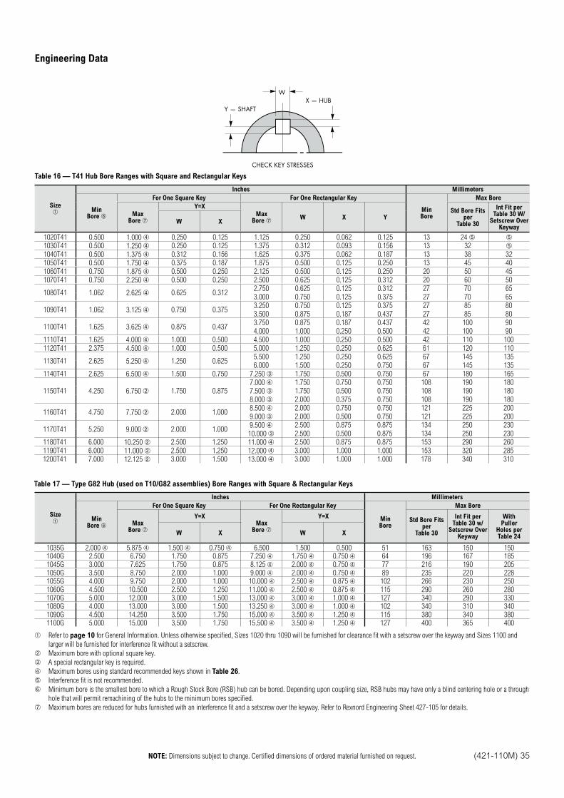
NOTE: Dimensions subject to change. Certified dimensions of ordered material furnished on request. (421-110M) 35
Engineering Data
Y — SHAFTX — HUB
CHECK KEY STRESSES
W
Table 16 — T41 Hub Bore Ranges with Square and Rectangular Keys
Size
Inches Millimeters
MinBore
For One Square Key For One Rectangular Key
MinBore
Max Bore
MaxBore
Y=X
MaxBore
W X YStd Bore Fits
perTable 30
Int Fit per Table 30 W/
Setscrew Over Keyway
W X
1020T41 0.500 1.000 0.250 0.125 1.125 0.250 0.062 0.125 13 24 1030T41 0.500 1.250 0.250 0.125 1.375 0.312 0.093 0.156 13 32
1040T41 0.500 1.375 0.312 0.156 1.625 0.375 0.062 0.187 13 38 32
1050T41 0.500 1.750 0.375 0.187 1.875 0.500 0.125 0.250 13 45 40
1060T41 0.750 1.875 0.500 0.250 2.125 0.500 0.125 0.250 20 50 45
1070T41 0.750 2.250 0.500 0.250 2.500 0.625 0.125 0.312 20 60 50
1080T41 1.062 2.625 0.625 0.3122.750 0.625 0.125 0.312 27 70 65
3.000 0.750 0.125 0.375 27 70 65
1090T41 1.062 3.125 0.750 0.3753.250 0.750 0.125 0.375 27 85 80
3.500 0.875 0.187 0.437 27 85 80
1100T41 1.625 3.625 0.875 0.4373.750 0.875 0.187 0.437 42 100 90
4.000 1.000 0.250 0.500 42 100 90
1110T41 1.625 4.000 1.000 0.500 4.500 1.000 0.250 0.500 42 110 100
1120T41 2.375 4.500 1.000 0.500 5.000 1.250 0.250 0.625 61 120 110
1130T41 2.625 5.250 1.250 0.6255.500 1.250 0.250 0.625 67 145 135
6.000 1.500 0.250 0.750 67 145 135
1140T41 2.625 6.500 1.500 0.750 7.250 1.750 0.500 0.750 67 180 165
1150T41 4.250 6.750 1.750 0.8757.000 1.750 0.750 0.750 108 190 180
7.500 1.750 0.500 0.750 108 190 180
8.000 2.000 0.375 0.750 108 190 180
1160T41 4.750 7.750 2.000 1.0008.500 2.000 0.750 0.750 121 225 200
9.000 2.000 0.500 0.750 121 225 200
1170T41 5.250 9.000 2.000 1.0009.500 2.500 0.875 0.875 134 250 230
10.000 2.500 0.500 0.875 134 250 230
1180T41 6.000 10.250 2.500 1.250 11.000 2.500 0.875 0.875 153 290 260
1190T41 6.000 11.000 2.500 1.250 12.000 3.000 1.000 1.000 153 320 285
1200T41 7.000 12.125 3.000 1.500 13.000 3.000 1.000 1.000 178 340 310
Table 17 — Type G82 Hub (used on T10/G82 assemblies) Bore Ranges with Square & Rectangular Keys
Size
Inches Millimeters
MinBore
For One Square Key For One Rectangular Key
MinBore
Max Bore
MaxBore
Y=XMax
Bore
Y=XStd Bore Fits
perTable 30
Int Fit per Table 30 w/
Setscrew Over Keyway
WithPuller
Holes perTable 24
W X W X
1035G 2.000 5.875 1.500 0.750 6.500 1.500 0.500 51 163 150 1501040G 2.500 6.750 1.750 0.875 7.250 1.750 0.750 64 196 167 1851045G 3.000 7.625 1.750 0.875 8.125 2.000 0.750 77 216 190 2051050G 3.500 8.750 2.000 1.000 9.000 2.000 0.750 89 235 220 2281055G 4.000 9.750 2.000 1.000 10.000 2.500 0.875 102 266 230 2501060G 4.500 10.500 2.500 1.250 11.000 2.500 0.875 115 290 260 2801070G 5.000 12.000 3.000 1.500 13.000 3.000 1.000 127 340 290 3301080G 4.000 13.000 3.000 1.500 13.250 3.000 1.000 102 340 310 3401090G 4.500 14.250 3.500 1.750 15.000 3.500 1.250 115 380 340 3801100G 5.000 15.000 3.500 1.750 15.500 3.500 1.250 127 400 365 400
Refer to page 10 for General Information. Unless otherwise specified, Sizes 1020 thru 1090 will be furnished for clearance fit with a setscrew over the keyway and Sizes 1100 and
larger will be furnished for interference fit without a setscrew.
Maximum bore with optional square key.
A special rectangular key is required.
Maximum bores using standard recommended keys shown in Table 26.
Interference fit is not recommended.
Minimum bore is the smallest bore to which a Rough Stock Bore (RSB) hub can be bored. Depending upon coupling size, RSB hubs may have only a blind centering hole or a through
hole that will permit remachining of the hubs to the minimum bores specified.
Maximum bores are reduced for hubs furnished with an interference fit and a setscrew over the keyway. Refer to Rexnord Engineering Sheet 427-105 for details.
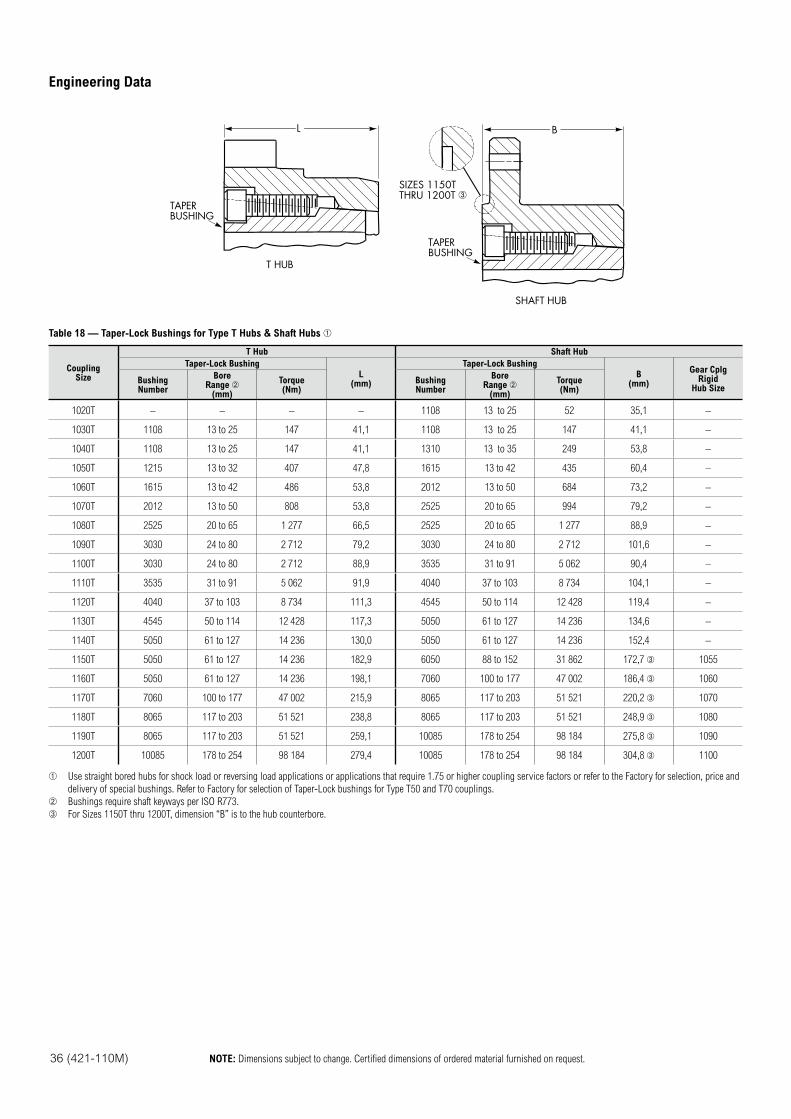
36 (421-110M) NOTE: Dimensions subject to change. Certified dimensions of ordered material furnished on request.
Engineering Data
L
TAPERBUSHING
B
SHAFT HUB
T HUB
TAPERBUSHING
SIZES 1150TTHRU 1200T
Table 18 — Taper-Lock Bushings for Type T Hubs & Shaft Hubs
CouplingSize
T Hub Shaft Hub
Taper-Lock Bushing
L(mm)
Taper-Lock Bushing
B(mm)
Gear CplgRigid
Hub SizeBushingNumber
BoreRange
(mm)
Torque(Nm)
BushingNumber
BoreRange
(mm)
Torque(Nm)
1020T – – – – 1108 13 to 25 52 35,1 –
1030T 1108 13 to 25 147 41,1 1108 13 to 25 147 41,1 –
1040T 1108 13 to 25 147 41,1 1310 13 to 35 249 53,8 –
1050T 1215 13 to 32 407 47,8 1615 13 to 42 435 60,4 –
1060T 1615 13 to 42 486 53,8 2012 13 to 50 684 73,2 –
1070T 2012 13 to 50 808 53,8 2525 20 to 65 994 79,2 –
1080T 2525 20 to 65 1 277 66,5 2525 20 to 65 1 277 88,9 –
1090T 3030 24 to 80 2 712 79,2 3030 24 to 80 2 712 101,6 –
1100T 3030 24 to 80 2 712 88,9 3535 31 to 91 5 062 90,4 –
1110T 3535 31 to 91 5 062 91,9 4040 37 to 103 8 734 104,1 –
1120T 4040 37 to 103 8 734 111,3 4545 50 to 114 12 428 119,4 –
1130T 4545 50 to 114 12 428 117,3 5050 61 to 127 14 236 134,6 –
1140T 5050 61 to 127 14 236 130,0 5050 61 to 127 14 236 152,4 –
1150T 5050 61 to 127 14 236 182,9 6050 88 to 152 31 862 172,7 1055
1160T 5050 61 to 127 14 236 198,1 7060 100 to 177 47 002 186,4 1060
1170T 7060 100 to 177 47 002 215,9 8065 117 to 203 51 521 220,2 1070
1180T 8065 117 to 203 51 521 238,8 8065 117 to 203 51 521 248,9 1080
1190T 8065 117 to 203 51 521 259,1 10085 178 to 254 98 184 275,8 1090
1200T 10085 178 to 254 98 184 279,4 10085 178 to 254 98 184 304,8 1100
Use straight bored hubs for shock load or reversing load applications or applications that require 1.75 or higher coupling service factors or refer to the Factory for selection, price and
delivery of special bushings. Refer to Factory for selection of Taper-Lock bushings for Type T50 and T70 couplings.
Bushings require shaft keyways per ISO R773.
For Sizes 1150T thru 1200T, dimension “B” is to the hub counterbore.
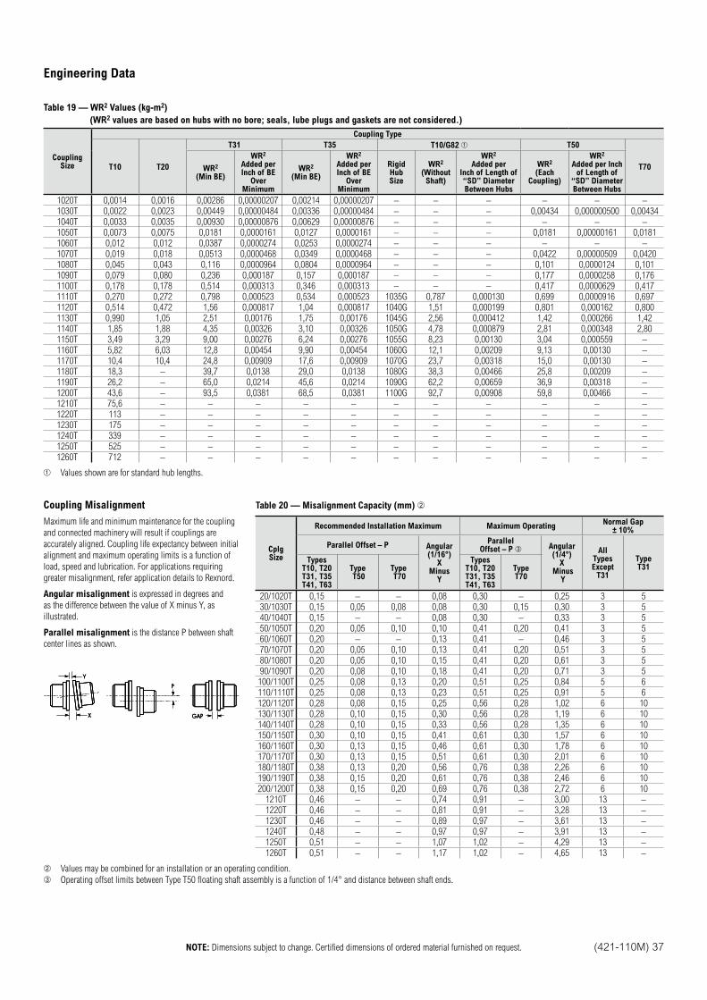
NOTE: Dimensions subject to change. Certified dimensions of ordered material furnished on request. (421-110M) 37
Engineering Data
Table 19 — WR2 Values (kg-m2)
(WR2 values are based on hubs with no bore; seals, lube plugs and gaskets are not considered.)
CouplingSize
Coupling Type
T10 T20
T31 T35 T10/G82 T50
T70WR2
(Min BE)
WR2
Added per Inch of BE
Over Minimum
WR2
(Min BE)
WR2
Added per Inch of BE
Over Minimum
RigidHubSize
WR2
(Without Shaft)
WR2
Added per Inch of Length of “SD” Diameter Between Hubs
WR2
(Each Coupling)
WR2
Added per Inch of Length of
“SD” Diameter Between Hubs
1020T 0,0014 0,0016 0,00286 0,00000207 0,00214 0,00000207 – – – – – –
1030T 0,0022 0,0023 0,00449 0,00000484 0,00336 0,00000484 – – – 0,00434 0,000000500 0,00434
1040T 0,0033 0,0035 0,00930 0,00000876 0,00629 0,00000876 – – – – – –
1050T 0,0073 0,0075 0,0181 0,0000161 0,0127 0,0000161 – – – 0,0181 0,00000161 0,0181
1060T 0,012 0,012 0,0387 0,0000274 0,0253 0,0000274 – – – – – –
1070T 0,019 0,018 0,0513 0,0000468 0,0349 0,0000468 – – – 0,0422 0,00000509 0,0420
1080T 0,045 0,043 0,116 0,0000964 0,0804 0,0000964 – – – 0,101 0,0000124 0,101
1090T 0,079 0,080 0,236 0,000187 0,157 0,000187 – – – 0,177 0,0000258 0,176
1100T 0,178 0,178 0,514 0,000313 0,346 0,000313 – – – 0,417 0,0000629 0,417
1110T 0,270 0,272 0,798 0,000523 0,534 0,000523 1035G 0,787 0,000130 0,699 0,0000916 0,697
1120T 0,514 0,472 1,56 0,000817 1,04 0,000817 1040G 1,51 0,000199 0,801 0,000162 0,800
1130T 0,990 1,05 2,51 0,00176 1,75 0,00176 1045G 2,56 0,000412 1,42 0,000266 1,42
1140T 1,85 1,88 4,35 0,00326 3,10 0,00326 1050G 4,78 0,000879 2,81 0,000348 2,80
1150T 3,49 3,29 9,00 0,00276 6,24 0,00276 1055G 8,23 0,00130 3,04 0,000559 –
1160T 5,82 6,03 12,8 0,00454 9,90 0,00454 1060G 12,1 0,00209 9,13 0,00130 –
1170T 10,4 10,4 24,8 0,00909 17,6 0,00909 1070G 23,7 0,00318 15,0 0,00130 –
1180T 18,3 – 39,7 0,0138 29,0 0,0138 1080G 38,3 0,00466 25,8 0,00209 –
1190T 26,2 – 65,0 0,0214 45,6 0,0214 1090G 62,2 0,00659 36,9 0,00318 –
1200T 43,6 – 93,5 0,0381 68,5 0,0381 1100G 92,7 0,00908 59,8 0,00466 –
1210T 75,6 – – – – – – – – – – –
1220T 113 – – – – – – – – – – –
1230T 175 – – – – – – – – – – –
1240T 339 – – – – – – – – – – –
1250T 525 – – – – – – – – – – –
1260T 712 – – – – – – – – – – –
Values shown are for standard hub lengths.
Coupling Misalignment
Maximum life and minimum maintenance for the coupling
and connected machinery will result if couplings are
accurately aligned. Coupling life expectancy between initial
alignment and maximum operating limits is a function of
load, speed and lubrication. For applications requiring
greater misalignment, refer application details to Rexnord.
Angular misalignment is expressed in degrees and
as the difference between the value of X minus Y, as
illustrated.
Parallel misalignment is the distance P between shaft
center lines as shown.
GAP
P
Y
X GAP
P
Y
X GAP
P
Y
X
Table 20 — Misalignment Capacity (mm)
CplgSize
Recommended Installation Maximum Maximum OperatingNormal Gap
± 10%
Parallel Offset – P Angular(1/16°)
XMinus
Y
ParallelOffset – P Angular
(1/4°)X
Minus Y
AllTypesExcept
T31
TypeT31
TypesT10, T20T31, T35T41, T63
Type T50
Type T70
TypesT10, T20T31, T35T41, T63
TypeT70
20/1020T 0,15 – – 0,08 0,30 – 0,25 3 5
30/1030T 0,15 0,05 0,08 0,08 0,30 0,15 0,30 3 5
40/1040T 0,15 – – 0,08 0,30 – 0,33 3 5
50/1050T 0,20 0,05 0,10 0,10 0,41 0,20 0,41 3 5
60/1060T 0,20 – – 0,13 0,41 – 0,46 3 5
70/1070T 0,20 0,05 0,10 0,13 0,41 0,20 0,51 3 5
80/1080T 0,20 0,05 0,10 0,15 0,41 0,20 0,61 3 5
90/1090T 0,20 0,08 0,10 0,18 0,41 0,20 0,71 3 5
100/1100T 0,25 0,08 0,13 0,20 0,51 0,25 0,84 5 6
110/1110T 0,25 0,08 0,13 0,23 0,51 0,25 0,91 5 6
120/1120T 0,28 0,08 0,15 0,25 0,56 0,28 1,02 6 10
130/1130T 0,28 0,10 0,15 0,30 0,56 0,28 1,19 6 10
140/1140T 0,28 0,10 0,15 0,33 0,56 0,28 1,35 6 10
150/1150T 0,30 0,10 0,15 0,41 0,61 0,30 1,57 6 10
160/1160T 0,30 0,13 0,15 0,46 0,61 0,30 1,78 6 10
170/1170T 0,30 0,13 0,15 0,51 0,61 0,30 2,01 6 10
180/1180T 0,38 0,13 0,20 0,56 0,76 0,38 2,26 6 10
190/1190T 0,38 0,15 0,20 0,61 0,76 0,38 2,46 6 10
200/1200T 0,38 0,15 0,20 0,69 0,76 0,38 2,72 6 10
1210T 0,46 – – 0,74 0,91 – 3,00 13 –
1220T 0,46 – – 0,81 0,91 – 3,28 13 –
1230T 0,46 – – 0,89 0,97 – 3,61 13 –
1240T 0,48 – – 0,97 0,97 – 3,91 13 –
1250T 0,51 – – 1,07 1,02 – 4,29 13 –
1260T 0,51 – – 1,17 1,02 – 4,65 13 –
Values may be combined for an installation or an operating condition.
Operating offset limits between Type T50 floating shaft assembly is a function of 1/4° and distance between shaft ends.
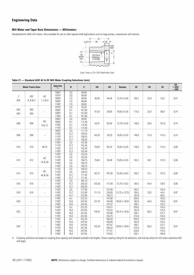
38 (421-110M) NOTE: Dimensions subject to change. Certified dimensions of ordered material furnished on request.
Engineering Data
Mill Motor and Taper Bore Dimensions — Millimeters
Standardized for AISE mill motors. Also available for use on other tapered shaft applications such as large pumps, compressors and turbines.
GAPSIDE
R
ZDZHZC
UHBASICDIA.
ZE
KEYWAYPARALLELTO BORE UG
Z
Type T Hub or T31/T35 Shaft Hubs Only
Table 21 — Standard AISE AC & DC Mill Motor Coupling Selections (mm)
Motor Frame SizesCplg Size
R Z UG UH Keyway ZC ZD ZEZH
+.XXX–.000
2
602
802
A, B & C
AC
1, 2 & 4
1060T 3,0 66,68
36,50 44,46 12,70 x 6,35 100,1 23,9 76,2 0,61
1070T 3,0 66,68
1080T 7,9 88,90
1090T 7,9 88,90
1100T 7,9 88,90
603
604
803
804–
1070T 3,0 76,20
41,53 50,80 19,05 x 6,35 114,3 25,4 88,9 0,741080T 9,7 101,60
1090T 9,7 101,60
1100T 9,7 101,60
606 806AC
8 & 12
1080T 3,0 88,90
52,91 63,50 12,70 x 6,35 130,0 28,4 101,6 0,741090T 9,7 114,30
1100T 9,7 114,30
1110T 9,7 114,30
608 808 –
1090T 3,0 111,13
64,29 76,20 19,05 x 6,35 146,0 31,8 114,3 0,741100T 12,7 136,53
1110T 12,7 136,53
1120T 12,7 136,53
610 810 AC18
1100T 3,0 127,00
70,64 82,55 19,05 x 6,35 149,4 35,1 114,3 0,861110T 12,7 152,40
1120T 12,7 152,40
1130T 12,7 152,40
612 812AC
25 & 30
1100T 3,0 133,35
78,84 92,08 19,05 x 6,35 165,1 38,1 127,0 0,86
1110T 3,0 133,35
1120T 3,0 158,75
1130T 3,0 158,75
1140T 3,0 158,75
614 814AC
40 & 50
1110T 3,0 149,23
94,72 107,95 25,40 x 9,53 168,1 41,1 127,0 0,861120T 3,0 149,23
1130T 12,7 171,45
1140T 12,7 171,45
616 816 –
1120T 3,0 165,10
102,92 117,48 31,75 x 9,53 184,2 44,4 139,7 0,861130T 15,7 203,20
1140T 15,7 203,20
618 818 –
1130T 3,0 177,80
111,13
127,00
31,75 x 12,70
185,7
33,3
152,4
0,971140T 15,7 215,90 126,85 184,2 44,4
1150T 15,7 215,90 126,72 182,9 60,5
620 – –
1140T 6,4 222,25
131,37
147,98
38,05 x 19,05
204,0
44,4
159,5
0,971150T 19,0 247,65 145,80 182,9 138,4
1160T 19,0 247,65 147,37 198,1 153,7
622 – –
1140T 6,4 222,25
139,57
154,51
38,10 x 19,05
204,0
60,5
143,5
0,971150T 19,0 247,65 152,32 182,9 122,4
1160T 19,0 247,65 153,90 198,1 137,7
1170T 19,0 247,65 155,75 215,9 155,4
624 – –
1140T 6,4 222,25
153,34
168,28
38,05 x 19,05
204,0
60,5
143,5
0,97
1150T 19,0 247,65 166,09 182,9 122,4
1160T 19,0 247,65 167,67 198,1 137,7
1170T 19,0 247,65 169,52 215,9 155,4
1180T 19,0 247,65 171,91 238,8 178,3
1190T 19,0 247,65 174,02 259,1 198,6
Coupling selections are based on coupling bore capacity and standard available hub lengths. Check coupling rating for all selections, and hub key stress for mill motor selections 620
and larger.
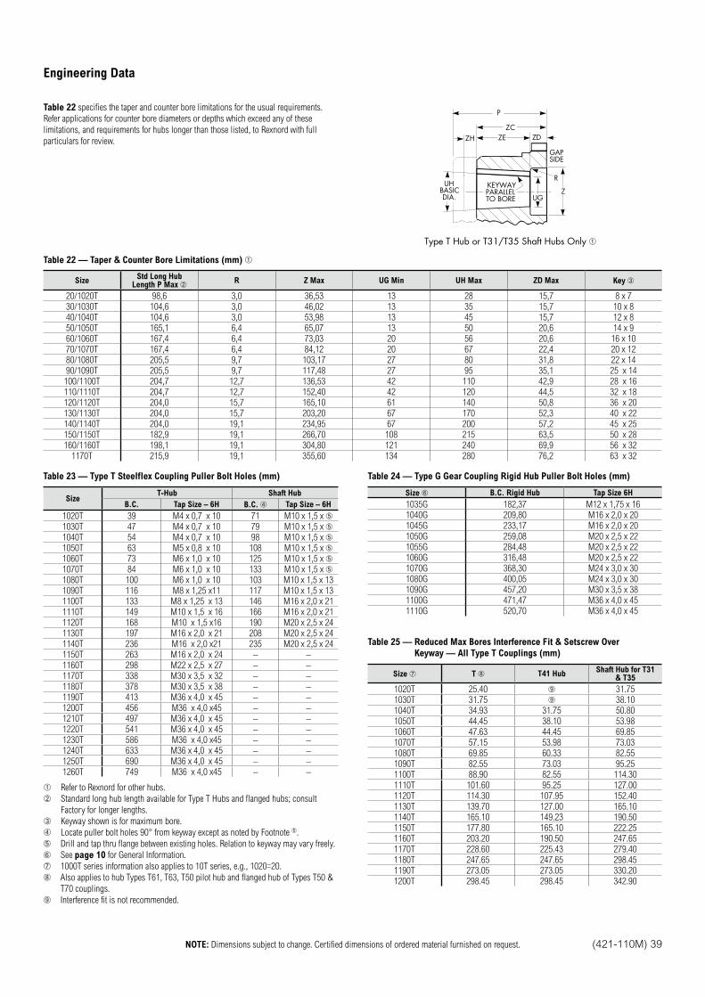
NOTE: Dimensions subject to change. Certified dimensions of ordered material furnished on request. (421-110M) 39
Engineering Data
Table 22 specifies the taper and counter bore limitations for the usual requirements.
Refer applications for counter bore diameters or depths which exceed any of these
limitations, and requirements for hubs longer than those listed, to Rexnord with full
particulars for review.
GAPSIDE
R
ZDZH
P
ZC
UHBASICDIA.
ZE
KEYWAYPARALLELTO BORE UG
Z
Type T Hub or T31/T35 Shaft Hubs Only
Table 22 — Taper & Counter Bore Limitations (mm)
SizeStd Long Hub
Length P Max R Z Max UG Min UH Max ZD Max Key
20/1020T 98,6 3,0 36,53 13 28 15,7 8 x 7
30/1030T 104,6 3,0 46,02 13 35 15,7 10 x 8
40/1040T 104,6 3,0 53,98 13 45 15,7 12 x 8
50/1050T 165,1 6,4 65,07 13 50 20,6 14 x 9
60/1060T 167,4 6,4 73,03 20 56 20,6 16 x 10
70/1070T 167,4 6,4 84,12 20 67 22,4 20 x 12
80/1080T 205,5 9,7 103,17 27 80 31,8 22 x 14
90/1090T 205,5 9,7 117,48 27 95 35,1 25 x 14
100/1100T 204,7 12,7 136,53 42 110 42,9 28 x 16
110/1110T 204,7 12,7 152,40 42 120 44,5 32 x 18
120/1120T 204,0 15,7 165,10 61 140 50,8 36 x 20
130/1130T 204,0 15,7 203,20 67 170 52,3 40 x 22
140/1140T 204,0 19,1 234,95 67 200 57,2 45 x 25
150/1150T 182,9 19,1 266,70 108 215 63,5 50 x 28
160/1160T 198,1 19,1 304,80 121 240 69,9 56 x 32
1170T 215,9 19,1 355,60 134 280 76,2 63 x 32
Table 23 — Type T Steelflex Coupling Puller Bolt Holes (mm)
SizeT-Hub Shaft Hub
B.C. Tap Size – 6H B.C. Tap Size – 6H
1020T 39 M4 x 0,7 x 10 71 M10 x 1,5 x
1030T 47 M4 x 0,7 x 10 79 M10 x 1,5 x
1040T 54 M4 x 0,7 x 10 98 M10 x 1,5 x
1050T 63 M5 x 0,8 x 10 108 M10 x 1,5 x
1060T 73 M6 x 1,0 x 10 125 M10 x 1,5 x
1070T 84 M6 x 1,0 x 10 133 M10 x 1,5 x
1080T 100 M6 x 1,0 x 10 103 M10 x 1,5 x 13
1090T 116 M8 x 1,25 x11 117 M10 x 1,5 x 13
1100T 133 M8 x 1,25 x 13 146 M16 x 2,0 x 21
1110T 149 M10 x 1,5 x 16 166 M16 x 2,0 x 21
1120T 168 M10 x 1,5 x16 190 M20 x 2,5 x 24
1130T 197 M16 x 2,0 x 21 208 M20 x 2,5 x 24
1140T 236 M16 x 2,0 x21 235 M20 x 2,5 x 24
1150T 263 M16 x 2,0 x 24 – –
1160T 298 M22 x 2,5 x 27 – –
1170T 338 M30 x 3,5 x 32 – –
1180T 378 M30 x 3,5 x 38 – –
1190T 413 M36 x 4,0 x 45 – –
1200T 456 M36 x 4,0 x45 – –
1210T 497 M36 x 4,0 x 45 – –
1220T 541 M36 x 4,0 x 45 – –
1230T 586 M36 x 4,0 x45 – –
1240T 633 M36 x 4,0 x 45 – –
1250T 690 M36 x 4,0 x 45 – –
1260T 749 M36 x 4,0 x45 – –
Refer to Rexnord for other hubs.
Standard long hub length available for Type T Hubs and flanged hubs; consult
Factory for longer lengths.
Keyway shown is for maximum bore.
Locate puller bolt holes 90° from keyway except as noted by Footnote .
Drill and tap thru flange between existing holes. Relation to keyway may vary freely.
See page 10 for General Information.
1000T series information also applies to 10T series, e.g., 1020=20.
Also applies to hub Types T61, T63, T50 pilot hub and flanged hub of Types T50 &
T70 couplings.
Interference fit is not recommended.
Table 24 — Type G Gear Coupling Rigid Hub Puller Bolt Holes (mm)
Size B.C. Rigid Hub Tap Size 6H
1035G 182,37 M12 x 1,75 x 16
1040G 209,80 M16 x 2,0 x 20
1045G 233,17 M16 x 2,0 x 20
1050G 259,08 M20 x 2,5 x 22
1055G 284,48 M20 x 2,5 x 22
1060G 316,48 M20 x 2,5 x 22
1070G 368,30 M24 x 3,0 x 30
1080G 400,05 M24 x 3,0 x 30
1090G 457,20 M30 x 3,5 x 38
1100G 471,47 M36 x 4,0 x 45
1110G 520,70 M36 x 4,0 x 45
Table 25 — Reduced Max Bores Interference Fit & Setscrew Over
Keyway — All Type T Couplings (mm)
Size T T41 HubShaft Hub for T31
& T35
1020T 25.40 31.75
1030T 31.75 38.10
1040T 34.93 31.75 50.80
1050T 44.45 38.10 53.98
1060T 47.63 44.45 69.85
1070T 57.15 53.98 73.03
1080T 69.85 60.33 82.55
1090T 82.55 73.03 95.25
1100T 88.90 82.55 114.30
1110T 101.60 95.25 127.00
1120T 114.30 107.95 152.40
1130T 139.70 127.00 165.10
1140T 165.10 149.23 190.50
1150T 177.80 165.10 222.25
1160T 203.20 190.50 247.65
1170T 228.60 225.43 279.40
1180T 247.65 247.65 298.45
1190T 273.05 273.05 330.20
1200T 298.45 298.45 342.90
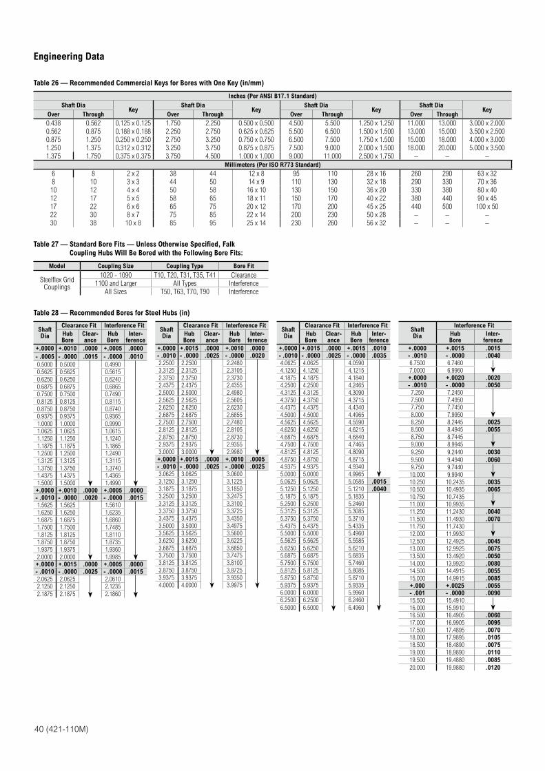
40 (421-110M)
Engineering Data
Table 26 — Recommended Commercial Keys for Bores with One Key (in/mm)
Inches (Per ANSI B17.1 Standard)
Shaft DiaKey
Shaft DiaKey
Shaft DiaKey
Shaft DiaKey
Over Through Over Through Over Through Over Through
0.438 0.562 0.125 x 0.125 1.750 2.250 0.500 x 0.500 4.500 5.500 1.250 x 1.250 11.000 13.000 3.000 x 2.000
0.562 0.875 0.188 x 0.188 2.250 2.750 0.625 x 0.625 5.500 6.500 1.500 x 1.500 13.000 15.000 3.500 x 2.500
0.875 1.250 0.250 x 0.250 2.750 3.250 0.750 x 0.750 6.500 7.500 1.750 x 1.500 15.000 18.000 4.000 x 3.000
1.250 1.375 0.312 x 0.312 3.250 3.750 0.875 x 0.875 7.500 9.000 2.000 x 1.500 18.000 20.000 5.000 x 3.500
1.375 1.750 0.375 x 0.375 3.750 4.500 1.000 x 1.000 9.000 11.000 2.500 x 1.750 – – –
Millimeters (Per ISO R773 Standard)
6 8 2 x 2 38 44 12 x 8 95 110 28 x 16 260 290 63 x 32
8 10 3 x 3 44 50 14 x 9 110 130 32 x 18 290 330 70 x 36
10 12 4 x 4 50 58 16 x 10 130 150 36 x 20 330 380 80 x 40
12 17 5 x 5 58 65 18 x 11 150 170 40 x 22 380 440 90 x 45
17 22 6 x 6 65 75 20 x 12 170 200 45 x 25 440 500 100 x 50
22 30 8 x 7 75 85 22 x 14 200 230 50 x 28 – – –
30 38 10 x 8 85 95 25 x 14 230 260 56 x 32 – – –
Table 27 — Standard Bore Fits — Unless Otherwise Specified, Falk
Coupling Hubs Will Be Bored with the Following Bore Fits:
Model Coupling Size Coupling Type Bore Fit
Steelflex Grid Couplings
1020 - 1090 T10, T20, T31, T35, T41 Clearance
1100 and Larger All Types Interference
All Sizes T50, T63, T70, T90 Interference
Table 28 — Recommended Bores for Steel Hubs (in)
ShaftDia
Clearance Fit Interference Fit
HubBore
Clear-ance
HubBore
Inter-ference
+.0000 +.0010 .0000 +.0005 .0000
- .0005 - .0000 .0015 - .0000 .0010
0.5000 0.5000 0.4990
0.5625 0.5625 0.5615
0.6250 0.6250 0.6240
0.6875 0.6875 0.6865
0.7500 0.7500 0.7490
0.8125 0.8125 0.8115
0.8750 0.8750 0.8740
0.9375 0.9375 0.9365
1.0000 1.0000 0.9990
1.0625 1.0625 1.0615
1.1250 1.1250 1.1240
1.1875 1.1875 1.1865
1.2500 1.2500 1.2490
1.3125 1.3125 1.3115
1.3750 1.3750 1.3740
1.4375 1.4375 1.4365
1.5000 1.5000 1.4990
+.0000 +.0010 .0000 +.0005 .0000
- .0010 - .0000 .0020 - .0000 .0015
1.5625 1.5625 1.5610
1.6250 1.6250 1.6235
1.6875 1.6875 1.6860
1.7500 1.7500 1.7485
1.8125 1.8125 1.8110
1.8750 1.8750 1.8735
1.9375 1.9375 1.9360
2.0000 2.0000 1.9985
+.0000 +.0015 .0000 +.0005 .0000
- .0010 - .0000 .0025 - .0000 .0015
2.0625 2.0625 2.0610
2.1250 2.1250 2.1235
2.1875 2.1875 2.1860
ShaftDia
Clearance Fit Interference Fit
HubBore
Clear-ance
HubBore
Inter-ference
+.0000 +.0015 .0000 +.0010 .0000
- .0010 - .0000 .0025 - .0000 .0020
2.2500 2.2500 2.2480
3.3125 2.3125 2.3105
2.3750 2.3750 2.3730
2.4375 2.4375 2.4355
2.5000 2.5000 2.4980
2.5625 2.5625 2.5605
2.6250 2.6250 2.6230
2.6875 2.6875 2.6855
2.7500 2.7500 2.7480
2.8125 2.8125 2.8105
2.8750 2.8750 2.8730
2.9375 2.9375 2.9355
3.0000 3.0000 2.9980
+.0000 +.0015 .0000 +.0010 .0005
- .0010 - .0000 .0025 - .0000 .0025
3.0625 3.0625 3.0600
3.1250 3.1250 3.1225
3.1875 3.1875 3.1850
3.2500 3.2500 3.2475
3.3125 3.3125 3.3100
3.3750 3.3750 3.3725
3.4375 3.4375 3.4350
3.5000 3.5000 3.4975
3.5625 3.5625 3.5600
3.6250 3.6250 3.6225
3.6875 3.6875 3.6850
3.7500 3.7500 3.7475
3.8125 3.8125 3.8100
3.8750 3.8750 3.8725
3.9375 3.9375 3.9350
4.0000 4.0000 3.9975
ShaftDia
Clearance Fit Interference Fit
HubBore
Clear-ance
HubBore
Inter-ference
+.0000 +.0015 .0000 +.0015 .0010
- .0010 - .0000 .0025 - .0000 .0035
4.0625 4.0625 4.0590
4.1250 4.1250 4.1215
4.1875 4.1875 4.1840
4.2500 4.2500 4.2465
4.3125 4.3125 4.3090
4.3750 4.3750 4.3715
4.4375 4.4375 4.4340
4.5000 4.5000 4.4965
4.5625 4.5625 4.5590
4.6250 4.6250 4.6215
4.6875 4.6875 4.6840
4.7500 4.7500 4.7465
4.8125 4.8125 4.8090
4.8750 4.8750 4.8715
4.9375 4.9375 4.9340
5.0000 5.0000 4.9965
5.0625 5.0625 5.0585 .0015
5.1250 5.1250 5.1210 .0040
5.1875 5.1875 5.1835
5.2500 5.2500 5.2460
5.3125 5.3125 5.3085
5.3750 5.3750 5.3710
5.4375 5.4375 5.4335
5.5000 5.5000 5.4960
5.5625 5.5625 5.5585
5.6250 5.6250 5.6210
5.6875 5.6875 5.6835
5.7500 5.7500 5.7460
5.8125 5.8125 5.8085
5.8750 5.8750 5.8710
5.9375 5.9375 5.9335
6.0000 6.0000 5.9960
6.2500 6.2500 6.2460
6.5000 6.5000 6.4960
ShaftDia
Interference Fit
HubBore
Inter-ference
+.0000 +.0015 .0015
- .0010 - .0000 .0040
6.7500 6.7460
7.0000 6.9960
+.0000 +.0020 .0020
- .0010 - .0000 .0050
7.250 7.2450
7.500 7.4950
7.750 7.7450
8.000 7.9950
8.250 8.2445 .0025
8.500 8.4945 .0055
8.750 8.7445
9.000 8.9945
9.250 9.2440 .0030
9.500 9.4940 .0060
9.750 9.7440
10.000 9.9940
10.250 10.2435 .0035
10.500 10.4935 .0065
10.750 10.7435
11.000 10.9935
11.250 11.2430 .0040
11.500 11.4930 .0070
11.750 11.7430
12.000 11.9930
12.500 12.4925 .0045
13.000 12.9925 .0075
13.500 13.4920 .0050
14.000 13.9920 .0080
14.500 14.4915 .0055
15.000 14.9915 .0085
+.000 +.0025 .0055
- .001 - .0000 .0090
15.500 15.4910
16.000 15.9910
16.500 16.4905 .0060
17.000 16.9905 .0095
17.500 17.4895 .0070
18.000 17.9895 .0105
18.500 18.4890 .0075
19.000 18.9890 .0110
19.500 19.4880 .0085
20.000 19.9880 .0120
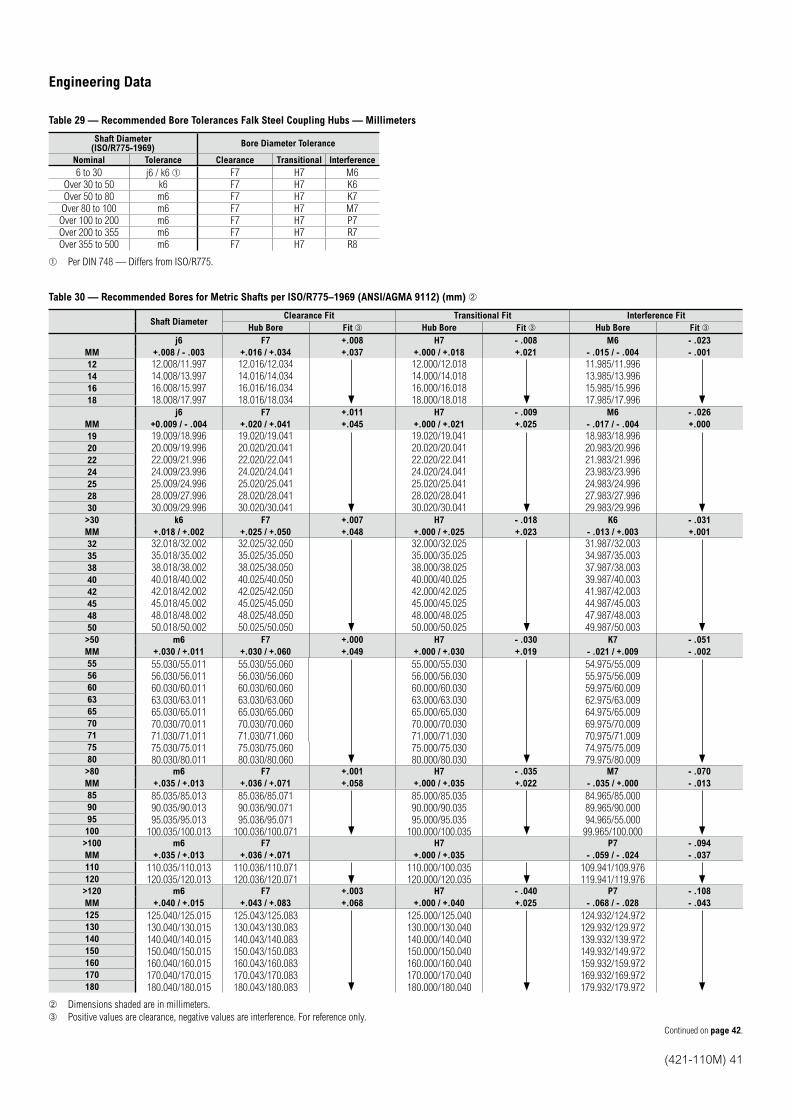
(421-110M) 41
Table 29 — Recommended Bore Tolerances Falk Steel Coupling Hubs — Millimeters
Shaft Diameter(ISO/R775-1969)
Bore Diameter Tolerance
Nominal Tolerance Clearance Transitional Interference
6 to 30 j6 / k6 F7 H7 M6
Over 30 to 50 k6 F7 H7 K6
Over 50 to 80 m6 F7 H7 K7
Over 80 to 100 m6 F7 H7 M7
Over 100 to 200 m6 F7 H7 P7
Over 200 to 355 m6 F7 H7 R7
Over 355 to 500 m6 F7 H7 R8
Per DIN 748 — Differs from ISO/R775.
Table 30 — Recommended Bores for Metric Shafts per ISO/R775–1969 (ANSI/AGMA 9112) (mm)
Shaft DiameterClearance Fit Transitional Fit Interference Fit
Hub Bore Fit Hub Bore Fit Hub Bore Fit
j6 F7 +.008 H7 - .008 M6 - .023
MM +.008 / - .003 +.016 / +.034 +.037 +.000 / +.018 +.021 - .015 / - .004 - .001
12 12.008/11.997 12.016/12.034 12.000/12.018 11.985/11.99614 14.008/13.997 14.016/14.034 14.000/14.018 13.985/13.99616 16.008/15.997 16.016/16.034 16.000/16.018 15.985/15.99618 18.008/17.997 18.016/18.034 18.000/18.018 17.985/17.996
j6 F7 +.011 H7 - .009 M6 - .026
MM +0.009 / - .004 +.020 / +.041 +.045 +.000 / +.021 +.025 - .017 / - .004 +.000
19 19.009/18.996 19.020/19.041 19.020/19.041 18.983/18.99620 20.009/19.996 20.020/20.041 20.020/20.041 20.983/20.99622 22.009/21.996 22.020/22.041 22.020/22.041 21.983/21.99624 24.009/23.996 24.020/24.041 24.020/24.041 23.983/23.99625 25.009/24.996 25.020/25.041 25.020/25.041 24.983/24.99628 28.009/27.996 28.020/28.041 28.020/28.041 27.983/27.99630 30.009/29.996 30.020/30.041 30.020/30.041 29.983/29.996>30 k6 F7 +.007 H7 - .018 K6 - .031
MM +.018 / +.002 +.025 / +.050 +.048 +.000 / +.025 +.023 - .013 / +.003 +.001
32 32.018/32.002 32.025/32.050 32.000/32.025 31.987/32.00335 35.018/35.002 35.025/35.050 35.000/35.025 34.987/35.00338 38.018/38.002 38.025/38.050 38.000/38.025 37.987/38.00340 40.018/40.002 40.025/40.050 40.000/40.025 39.987/40.00342 42.018/42.002 42.025/42.050 42.000/42.025 41.987/42.00345 45.018/45.002 45.025/45.050 45.000/45.025 44.987/45.00348 48.018/48.002 48.025/48.050 48.000/48.025 47.987/48.00350 50.018/50.002 50.025/50.050 50.000/50.025 49.987/50.003>50 m6 F7 +.000 H7 - .030 K7 - .051
MM +.030 / +.011 +.030 / +.060 +.049 +.000 / +.030 +.019 - .021 / +.009 - .002
55 55.030/55.011 55.030/55.060 55.000/55.030 54.975/55.00956 56.030/56.011 56.030/56.060 56.000/56.030 55.975/56.00960 60.030/60.011 60.030/60.060 60.000/60.030 59.975/60.00963 63.030/63.011 63.030/63.060 63.000/63.030 62.975/63.00965 65.030/65.011 65.030/65.060 65.000/65.030 64.975/65.00970 70.030/70.011 70.030/70.060 70.000/70.030 69.975/70.00971 71.030/71.011 71.030/71.060 71.000/71.030 70.975/71.00975 75.030/75.011 75.030/75.060 75.000/75.030 74.975/75.00980 80.030/80.011 80.030/80.060 80.000/80.030 79.975/80.009>80 m6 F7 +.001 H7 - .035 M7 - .070
MM +.035 / +.013 +.036 / +.071 +.058 +.000 / +.035 +.022 - .035 / +.000 - .013
85 85.035/85.013 85.036/85.071 85.000/85.035 84.965/85.00090 90.035/90.013 90.036/90.071 90.000/90.035 89.965/90.00095 95.035/95.013 95.036/95.071 95.000/95.035 94.965/55.000100 100.035/100.013 100.036/100.071 100.000/100.035 99.965/100.000>100 m6 F7 H7 P7 - .094
MM +.035 / +.013 +.036 / +.071 +.000 / +.035 - .059 / - .024 - .037
110 110.035/110.013 110.036/110.071 110.000/100.035 109.941/109.976120 120.035/120.013 120.036/120.071 120.000/120.035 119.941/119.976>120 m6 F7 +.003 H7 - .040 P7 - .108
MM +.040 / +.015 +.043 / +.083 +.068 +.000 / +.040 +.025 - .068 / - .028 - .043
125 125.040/125.015 125.043/125.083 125.000/125.040 124.932/124.972130 130.040/130.015 130.043/130.083 130.000/130.040 129.932/129.972140 140.040/140.015 140.043/140.083 140.000/140.040 139.932/139.972150 150.040/150.015 150.043/150.083 150.000/150.040 149.932/149.972160 160.040/160.015 160.043/160.083 160.000/160.040 159.932/159.972170 170.040/170.015 170.043/170.083 170.000/170.040 169.932/169.972180 180.040/180.015 180.043/180.083 180.000/180.040 179.932/179.972
Dimensions shaded are in millimeters.
Positive values are clearance, negative values are interference. For reference only.
Engineering Data
Continued on page 42.
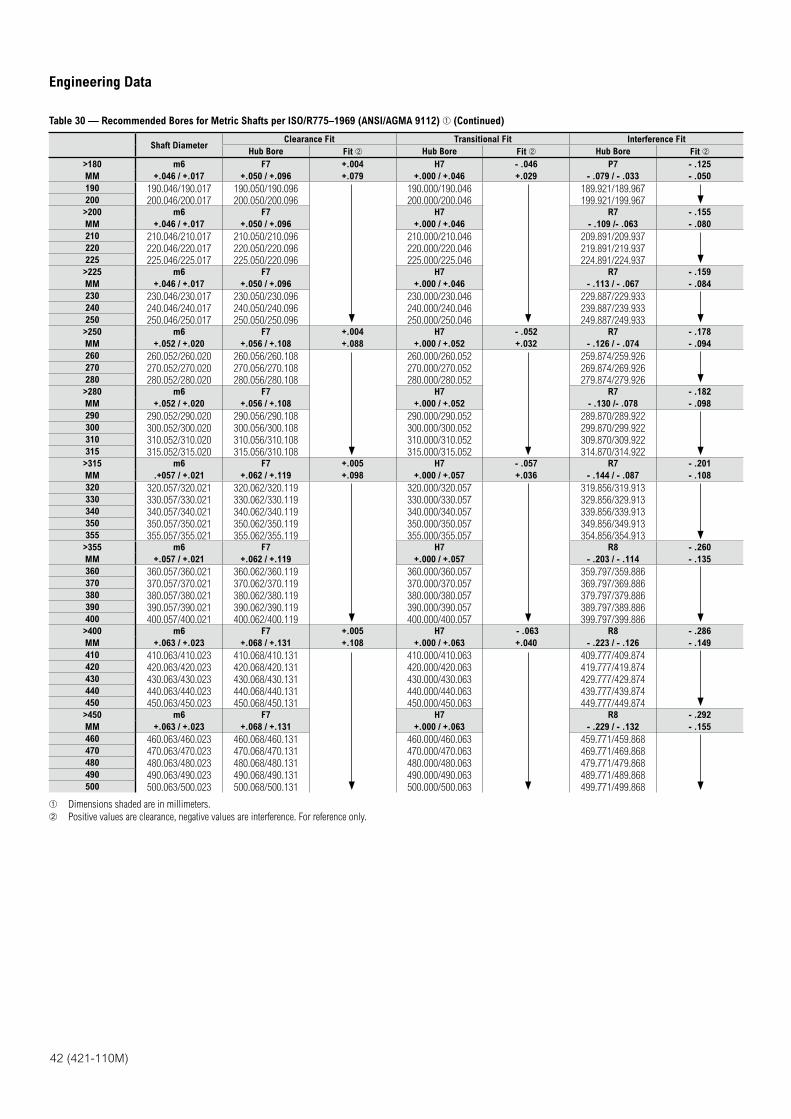
42 (421-110M)
Engineering Data
Table 30 — Recommended Bores for Metric Shafts per ISO/R775–1969 (ANSI/AGMA 9112) (Continued)
Shaft DiameterClearance Fit Transitional Fit Interference Fit
Hub Bore Fit Hub Bore Fit Hub Bore Fit
>180 m6 F7 +.004 H7 - .046 P7 - .125
MM +.046 / +.017 +.050 / +.096 +.079 +.000 / +.046 +.029 - .079 / - .033 - .050
190 190.046/190.017 190.050/190.096 190.000/190.046 189.921/189.967200 200.046/200.017 200.050/200.096 200.000/200.046 199.921/199.967
>200 m6 F7 H7 R7 - .155
MM +.046 / +.017 +.050 / +.096 +.000 / +.046 - .109 /- .063 - .080
210 210.046/210.017 210.050/210.096 210.000/210.046 209.891/209.937220 220.046/220.017 220.050/220.096 220.000/220.046 219.891/219.937225 225.046/225.017 225.050/220.096 225.000/225.046 224.891/224.937
>225 m6 F7 H7 R7 - .159
MM +.046 / +.017 +.050 / +.096 +.000 / +.046 - .113 / - .067 - .084
230 230.046/230.017 230.050/230.096 230.000/230.046 229.887/229.933240 240.046/240.017 240.050/240.096 240.000/240.046 239.887/239.933250 250.046/250.017 250.050/250.096 250.000/250.046 249.887/249.933
>250 m6 F7 +.004 H7 - .052 R7 - .178
MM +.052 / +.020 +.056 / +.108 +.088 +.000 / +.052 +.032 - .126 / - .074 - .094
260 260.052/260.020 260.056/260.108 260.000/260.052 259.874/259.926270 270.052/270.020 270.056/270.108 270.000/270.052 269.874/269.926280 280.052/280.020 280.056/280.108 280.000/280.052 279.874/279.926
>280 m6 F7 H7 R7 - .182
MM +.052 / +.020 +.056 / +.108 +.000 / +.052 - .130 /- .078 - .098
290 290.052/290.020 290.056/290.108 290.000/290.052 289.870/289.922300 300.052/300.020 300.056/300.108 300.000/300.052 299.870/299.922310 310.052/310.020 310.056/310.108 310.000/310.052 309.870/309.922315 315.052/315.020 315.056/310.108 315.000/315.052 314.870/314.922
>315 m6 F7 +.005 H7 - .057 R7 - .201
MM .+057 / +.021 +.062 / +.119 +.098 +.000 / +.057 +.036 - .144 / - .087 - .108
320 320.057/320.021 320.062/320.119 320.000/320.057 319.856/319.913330 330.057/330.021 330.062/330.119 330.000/330.057 329.856/329.913340 340.057/340.021 340.062/340.119 340.000/340.057 339.856/339.913350 350.057/350.021 350.062/350.119 350.000/350.057 349.856/349.913355 355.057/355.021 355.062/355.119 355.000/355.057 354.856/354.913
>355 m6 F7 H7 R8 - .260
MM +.057 / +.021 +.062 / +.119 +.000 / +.057 - .203 / - .114 - .135
360 360.057/360.021 360.062/360.119 360.000/360.057 359.797/359.886370 370.057/370.021 370.062/370.119 370.000/370.057 369.797/369.886380 380.057/380.021 380.062/380.119 380.000/380.057 379.797/379.886390 390.057/390.021 390.062/390.119 390.000/390.057 389.797/389.886400 400.057/400.021 400.062/400.119 400.000/400.057 399.797/399.886
>400 m6 F7 +.005 H7 - .063 R8 - .286
MM +.063 / +.023 +.068 / +.131 +.108 +.000 / +.063 +.040 - .223 / - .126 - .149
410 410.063/410.023 410.068/410.131 410.000/410.063 409.777/409.874420 420.063/420.023 420.068/420.131 420.000/420.063 419.777/419.874430 430.063/430.023 430.068/430.131 430.000/430.063 429.777/429.874440 440.063/440.023 440.068/440.131 440.000/440.063 439.777/439.874450 450.063/450.023 450.068/450.131 450.000/450.063 449.777/449.874
>450 m6 F7 H7 R8 - .292
MM +.063 / +.023 +.068 / +.131 +.000 / +.063 - .229 / - .132 - .155
460 460.063/460.023 460.068/460.131 460.000/460.063 459.771/459.868470 470.063/470.023 470.068/470.131 470.000/470.063 469.771/469.868480 480.063/480.023 480.068/480.131 480.000/480.063 479.771/479.868490 490.063/490.023 490.068/490.131 490.000/490.063 489.771/489.868500 500.063/500.023 500.068/500.131 500.000/500.063 499.771/499.868
Dimensions shaded are in millimeters.
Positive values are clearance, negative values are interference. For reference only.
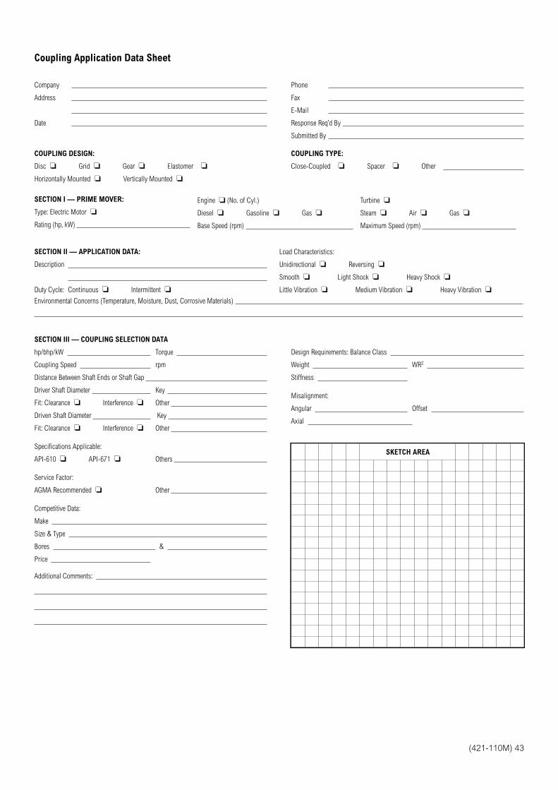
(421-110M) 43
Coupling Application Data Sheet
Company
Address
Date
Phone
Fax
Response Req’d By
Submitted By
COUPLING DESIGN:
Disc Grid Gear Elastomer
Horizontally Mounted Vertically Mounted
COUPLING TYPE:
Close-Coupled Spacer Other
SECTION I — PRIME MOVER:
Type: Electric Motor
Rating (hp, kW)
Engine (No. of Cyl.)
Diesel Gasoline Gas
Base Speed (rpm)
Turbine
Steam Air Gas
Maximum Speed (rpm)
SECTION II — APPLICATION DATA:
Description
Duty Cycle: Continuous Intermittent
Load Characteristics:
Unidirectional Reversing
Smooth Light Shock Heavy Shock
Little Vibration Medium Vibration Heavy Vibration
Environmental Concerns (Temperature, Moisture, Dust, Corrosive Materials)
SECTION III — COUPLING SELECTION DATA
hp/bhp/kW Torque
Coupling Speed rpm
Distance Between Shaft Ends or Shaft Gap
Driver Shaft Diameter Key
Fit: Clearance Interference Other
Driven Shaft Diameter Key
Fit: Clearance Interference Other
Specifications Applicable:
API-610 API-671 Others
Service Factor:
AGMA Recommended Other
Competitive Data:
Make
Size & Type
Bores &
Price
Additional Comments:
Design Requirements: Balance Class
Weight WR2
Stiffness
Misalignment:
Angular Offset
Axial
SKETCH AREA
©2014 Rexnord 421-110M Printed in USA 03/14
Why Choose Rexnord?When it comes to providing highly engineered products that improve productivity and efficiency for industrial applications worldwide, Rexnord is the most reliable in the industry. Commitment to customer satisfaction and superior value extend across every business function.
Delivering Lowest Total Cost of OwnershipThe highest quality products are designed to help prevent equipment downtime and increase productivity and dependable operation.
Valuable ExpertiseAn extensive product offering is accompanied by global sales specialists, customer service and maintenance support teams, available anytime.
Solutions to Enhance Ease of Doing BusinessCommitment to operational excellence ensures the right products at the right place at the right time.
866-REXNORD/866-739-6673 (Within the US)414-643-2366 (Outside the US)
www.rexnord.com
Rexnord CorporationRexnord is a growth-oriented, multi-platform industrial company with leading market shares and highly trusted brands that serve a diverse array of global end markets.
Process and Motion ControlThe Rexnord Process & Motion Control platform designs, manufactures, markets and services specified, highly engineered mechanical components used within complex systems where our customers’ reliability requirements and the cost of failure or downtime are extremely high.
Water ManagementThe Rexnord Water Management platform designs, procures, manufactures and markets products that provide and enhance water quality, safety, flow control and conservation.